EP3253535B1 - Work and storage table - Google Patents
Work and storage table Download PDFInfo
- Publication number
- EP3253535B1 EP3253535B1 EP16705408.9A EP16705408A EP3253535B1 EP 3253535 B1 EP3253535 B1 EP 3253535B1 EP 16705408 A EP16705408 A EP 16705408A EP 3253535 B1 EP3253535 B1 EP 3253535B1
- Authority
- EP
- European Patent Office
- Prior art keywords
- work
- support
- tool
- support frame
- storage table
- Prior art date
- Legal status (The legal status is an assumption and is not a legal conclusion. Google has not performed a legal analysis and makes no representation as to the accuracy of the status listed.)
- Active
Links
Images



Classifications
-
- B—PERFORMING OPERATIONS; TRANSPORTING
- B25—HAND TOOLS; PORTABLE POWER-DRIVEN TOOLS; MANIPULATORS
- B25H—WORKSHOP EQUIPMENT, e.g. FOR MARKING-OUT WORK; STORAGE MEANS FOR WORKSHOPS
- B25H1/00—Work benches; Portable stands or supports for positioning portable tools or work to be operated on thereby
- B25H1/02—Work benches; Portable stands or supports for positioning portable tools or work to be operated on thereby of table type
- B25H1/04—Work benches; Portable stands or supports for positioning portable tools or work to be operated on thereby of table type portable
-
- B—PERFORMING OPERATIONS; TRANSPORTING
- B25—HAND TOOLS; PORTABLE POWER-DRIVEN TOOLS; MANIPULATORS
- B25H—WORKSHOP EQUIPMENT, e.g. FOR MARKING-OUT WORK; STORAGE MEANS FOR WORKSHOPS
- B25H1/00—Work benches; Portable stands or supports for positioning portable tools or work to be operated on thereby
- B25H1/14—Work benches; Portable stands or supports for positioning portable tools or work to be operated on thereby with provision for adjusting the bench top
-
- B—PERFORMING OPERATIONS; TRANSPORTING
- B25—HAND TOOLS; PORTABLE POWER-DRIVEN TOOLS; MANIPULATORS
- B25H—WORKSHOP EQUIPMENT, e.g. FOR MARKING-OUT WORK; STORAGE MEANS FOR WORKSHOPS
- B25H3/00—Storage means or arrangements for workshops facilitating access to, or handling of, work tools or instruments
Definitions
- the present invention generally relates to a work bench which can also function as a tool support stand.
- Work benches and tool support stands are well known but typically separate products. Work benches come in many shapes and sizes but generally do not easily support most power tools that are intended to be mounted. Workbenches tend to have a large wide flat surface upon with a user can work on a project. They can have fixed or adjustable legs and may be stationary or transportable.
- tool support stands generally employ a top surface which is generally narrow to which a tool, such as a saw, can be mounted and legs to support the stand.
- These tool support stands come in any number of sizes and shapes, but typically have four legs that are fixed in the support position or can be individually folded or telescoped to a closed position. Some of these known tool support stands also include extendable work surfaces that can be pulled out to make the overall length of the tool stand longer.
- What is needed is a versatile, multipurpose tool stand and work bench that can be easily and quickly changed from a tool support to a workbench and provide storage for the tool. Additionally, the tool stand and work bench should be compact, but still provide the desired work area when needed.
- this invention provides a unique cuboid shaped work and storage table that has a rotatable top that exposes a work surface on one side and a unique universal tool mount on the opposite side.
- the work and storage table of the present invention includes a support frame having opposed sides with a two sided work top mounted between the opposed sides of the support frame for rotation with respect to the support frame.
- the work top has a flat surface on one side and a unique tool support surface on the opposite side.
- the work top can be rotated with respect to said support frame to expose the flat surface or the tool support surface. When that flat surface is exposed, any tool mounted to the tool support surface is stored underneath between the opposed sides.
- the tool support table has a generally cuboid shape.
- the work and storage table has a unique latch mechanism to lock the work top in place.
- the latch has a control disc from which locking rods extend and connect to pins that engage slots in the work top.
- the latch mechanism includes a handle that can be extended through the support frame. When not in use, the handle rest in a slot so that it doesn't obstruct the work surface.
- the handle is connected to the control disc such that the locking rods can be controlled from one locking handle.
- locking rods extend along the length of said support frame to lock the work top at the front and back
- the work and storage table may also includes a unique tool mount fixed to said tool support surface.
- the tool mount has at least two side walls and two tool mount slides mounted generally perpendicular to said side walls for sliding with respect to said side walls.
- the tool mount slides are adapted to attach to a tool and then mount to the two side walls.
- the unique tool mount provides a universal mount that can be used to mount any tool regardless of the configuration of the tool base, i.e. whether three point, four point and offset configuration.
- the work and storage table also includes side arms hinged to the opposed sides that rotate from a lowered position to a raised position.
- the side arms include a height adjustable secondary platform mounted upon a parallelogram such that the platform remains generally parallel when adjusted.
- the present invention relates to a tool support table and workbench combination generally shown at 10.
- the disclosed tool support table includes a frame having opposed sides, 12 and 14, a rear lower brace 20 and lower support tubes 16. Wheels 22 are mounted to the lower brace 20 at the opposed sides 12 and 14. The wheels 22 facilitate easy movement of the table 10.
- the lower support tubes 16 also include front stops 18 to support the table 10 in the upright position.
- the table 10 is a compact cuboid shape.
- the tool is in the stored position and the work surface 30 is exposed. Due to the cuboid shape of the table 10, and the general height, the work surface 30 can be positioned against a standard work bench and create an extension to the overall work surface.
- each one of the pair of the back tubes 24 and lower support tubes 16 are one single generally L-shaped tube extending from the back of the table 10 to the lower or bottom of the table 10. It will be appreciated by those of ordinary skill in the art that the back and lower support tubes 24 and 16 could be separate tubes.
- Each of the back support tubes 24 have a lower stop 26.
- the stops 26 support the table 10 when the table 10 is placed on its back for storage.
- the width of the table 10 of the present invention allows the table 10 to be placed on its back on stops 26 and slid under a normal height standard work bench.
- a handle 28 is mounted within the tubes 24. The handle 28 is mounted so that it can slide within the tubes 24 from a use position to a storage position. It should be appreciated that the handle 28 could also be hinged to the back support tubes 24 so that it can be folded rather than slid with respect to tube 24.
- a two sided worktop or rotating work surface 30 is mounted to the top of the opposed sides 12 and 14.
- the surface 30 is mounted at its midpoint to the sides 12 and 14. This allows for controlled rotation of the surface 30.
- the surface 30 is mounted to the sides 12 and 14 through pins 31. It should be appreciated that spring assists could be used to further facilitate rotation.
- the surface 30 has two sides, a flat work top 32 and a tool support 34. In the position illustrated in FIG. 1 , the flat worktop 32 is flush with the two sides 12 and 14 and open to the front and back of the table 10 to allow use of the work top 32 when placed adjacent to a work bench. As will be appreciated, the worktop 32 acts as an extended work surface.
- the tool support 34 is defined by sides 36. Two of the opposed sides 36 have spaced slots 38. A pair of sliding tool mounts 40 are mounted within the two opposed sides through the slots 38. Each of the tool mounts 40 has a slot 42 that extends generally perpendicular to the spaced slots 38.
- the tool mounts 40 are mounted within the spaced slots 38 by fasteners 44, such as for example threaded bolts.
- the tool mounts 40 can slide within the slots 38. In this way, a tool, such as a saw can be mounted to the slots 42 and the tool mounts 40 can be mounted to the opposed sides 36 through the spaced slots 38 and fasteners 44. In this way, the tool support is universal and can fit any tool.
- the tool mounts 40 are perpendicular to for example the saw blade of the tool which allows the tool to be mounted without offset brackets or 3 point mounting bars, see FIG. 9 .
- the table 30 can be rotated to a storage position, see FIG. 1 , and a use position, see FIG. 5 .
- the table 30 is locked in placed with a latch mechanism 60.
- the latch mechanism 60 includes a handle 62 extending through the top of one of the sides 12 Or 14.
- the side has a slot 61 to allow access to the handle 62.
- the latch 60 is connected to a control disc 64 form which locking rods 66 extend.
- the locking rods 66 extend along the length of the sides to the front and back.
- the locking rods 66 connect to pins 68.
- the pins 68 engage slots in the table 30 to lock the table 30 in place. As disclosed, the pins are spring loaded to facilitate locking.
- wing supports or side arms 46 are mounted to the opposed sides 12 and 14.
- the side arms 46 are mounted to rotate from a lowered position to a raised position see FIGS. 5 and 6 .
- the side arms 46 include a height adjustable secondary platform 48.
- the platforms 48 are mounted upon a parallelogram having four arms 50. In this way, the platform 48 is always parallel to the arm 46.
- the arms 46 have ratchet connections to allow them to rotate and be fixed at selected positions. In this way, the platform 48 can be rotated to a position parallel with the surface of the tool.
- the platform 48 provides an extended work support platform.
- the arms 46 include supports 50.
- the supports 50 in the disclosed embodiment fold when the side arms 46 are folded down. When raised, the side arms 46 pull the supports 50 to a locked position.
- a latch is also provided on each side arm 46 to latch the side arms in the raised position. It should be appreciated that other supports 50 could be used, for example a telescoping support.
- the table 10 is shown in the storage position. As discussed above, in this position, the table 10 can be used as a worktop 32. It can also be used as an extension to a worktable. With reference to FIG. 3 , the table 10 is shown in a further storage position. In this position, table 10 has been rotated to rest upon the back support tubes 24 and the stops 26. In this position, the overall height of the table 10 is less, allowing for storage under a worktable for example.
- the table 10 is shown in the use position. In this position, a tool, such as a miter saw, is mounted to the tool support 34. As will be appreciated, the work surface 30 is rotated from the storage position to the use position. With reference to FIG. 7 , the side arms 46 and platform 48 are illustrated.
Landscapes
- Engineering & Computer Science (AREA)
- Mechanical Engineering (AREA)
- Workshop Equipment, Work Benches, Supports, Or Storage Means (AREA)
Description
- This application claims the benefit of
U.S. Provisional Application No. 62/111,724 filed Feb. 3, 2015 U.S. Provisional Application No. 62/218,174 filed Sep. 14, 2015 - The present invention generally relates to a work bench which can also function as a tool support stand. Work benches and tool support stands are well known but typically separate products. Work benches come in many shapes and sizes but generally do not easily support most power tools that are intended to be mounted. Workbenches tend to have a large wide flat surface upon with a user can work on a project. They can have fixed or adjustable legs and may be stationary or transportable. By contrast, tool support stands generally employ a top surface which is generally narrow to which a tool, such as a saw, can be mounted and legs to support the stand. These tool support stands come in any number of sizes and shapes, but typically have four legs that are fixed in the support position or can be individually folded or telescoped to a closed position. Some of these known tool support stands also include extendable work surfaces that can be pulled out to make the overall length of the tool stand longer.
- Examples of applicant's tool support stands can be found in
U.S. Design Pat. Nos. D623,672 andD549,749 . - [0003(i)] other documents which are related with the state of the art are:
-
US2011232805 discloses an integrated work surface and tool storage system comprising a plurality of panels, forming a box-like shape, having a support structure, supporting at least the edges of the box-like shape formed by the plurality of panels; and a plurality of hinges coupled to the support structure, that enable the plurality of panels to have a storable position state that fold the panels into a box-like shape, and a deployable panel state where the panels form a flat work surface located above the support structure. -
WO2007063310 discloses a work bench module wherein the module comprising a planar work surface, a storage space being defined in the module below the work surface, equipment mounting means being provided on which a piece of equipment can be mounted in use, the equipment mounting means being itself mounted on the module so as to be moveable from a retracted position in which the piece of equipment is stored in the storage cavity to an operative position in which the piece of equipment can be accessed from the exterior of the module. -
US4733704 which discloses a workbench which includes a workpiece supporting panel carried by a trestle. -
US4874025 discloses a miter saw utility stand having a saw table top upon which the miter saw is to be mounted
-
- The difficulty with typical tool support stands is that they can be large and unwieldy. If the legs are fixed in place, it can be difficult to move the tool stand from job to job. This is true even if wheels are provided to roll the tool stand. Folding legs and extendible legs can be cumbersome. Each leg has to be extended or folded out to use the stand and collapsed to transport the stand. Additionally, the tool support stands do not make ideal work benches, the tool support stands are too narrow to truly function as a good work bench.
- Another problem with typical tool support stands is that the tool mounted to the support stand has to be removed for storage. The stands leave the tool exposed, there is not place on the stand to store the tools
- What is needed is a versatile, multipurpose tool stand and work bench that can be easily and quickly changed from a tool support to a workbench and provide storage for the tool. Additionally, the tool stand and work bench should be compact, but still provide the desired work area when needed.
- In general terms, this invention provides a unique cuboid shaped work and storage table that has a rotatable top that exposes a work surface on one side and a unique universal tool mount on the opposite side.
- The work and storage table of the present invention includes a support frame having opposed sides with a two sided work top mounted between the opposed sides of the support frame for rotation with respect to the support frame. The work top has a flat surface on one side and a unique tool support surface on the opposite side. The work top can be rotated with respect to said support frame to expose the flat surface or the tool support surface. When that flat surface is exposed, any tool mounted to the tool support surface is stored underneath between the opposed sides. For compactness, the tool support table has a generally cuboid shape.
- The work and storage table has a unique latch mechanism to lock the work top in place. The latch has a control disc from which locking rods extend and connect to pins that engage slots in the work top. The latch mechanism includes a handle that can be extended through the support frame. When not in use, the handle rest in a slot so that it doesn't obstruct the work surface. The handle is connected to the control disc such that the locking rods can be controlled from one locking handle. In the disclosed embodiment, locking rods extend along the length of said support frame to lock the work top at the front and back
- The work and storage table,not according to the invention, may also includes a unique tool mount fixed to said tool support surface. The tool mount has at least two side walls and two tool mount slides mounted generally perpendicular to said side walls for sliding with respect to said side walls. The tool mount slides are adapted to attach to a tool and then mount to the two side walls. The unique tool mount provides a universal mount that can be used to mount any tool regardless of the configuration of the tool base, i.e. whether three point, four point and offset configuration.
- The work and storage table also includes side arms hinged to the opposed sides that rotate from a lowered position to a raised position. The side arms include a height adjustable secondary platform mounted upon a parallelogram such that the platform remains generally parallel when adjusted.
- These and other features and advantages of this invention will become more apparent to those skilled in the art from the detailed description of a preferred embodiment. The drawings that accompany the detailed description are described below.
-
-
FIG. 1 is a perspective view of the tool support table of the present invention in the storage position. -
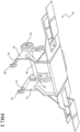
FIG. 2 is a perspective view of the tool support table of the present invention in the use position with the side arms rotated to the use position and the platforms raised. -
FIG. 3 is a perspective view of the tool support table of the present invention in the storage position resting on the back supports. -
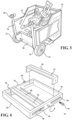
FIG. 4 is a perspective view of the tool support of the present invention. -
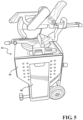
FIG. 5 is a perspective view of the tool support table of the present invention in the use position. -
FIG. 6 is a perspective view of the tool support table of the present invention in the storage position. -
FIG. 7 is a perspective view of the tool support table of the present invention in the use position with the side arms rotated to the use position and the platforms raised. -
FIG. 8 is a perspective view of the latch mechanism of the tool support present. -
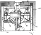
FIG. 9 is a top view of the tool mount of the present invention. -
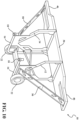
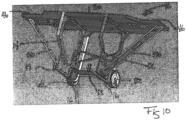
FIG. 10 is a perspective view of the tool support table of the present invention as viewed from the bottom. - The present invention relates to a tool support table and workbench combination generally shown at 10. The disclosed tool support table includes a frame having opposed sides, 12 and 14, a rear
lower brace 20 andlower support tubes 16.Wheels 22 are mounted to thelower brace 20 at theopposed sides wheels 22 facilitate easy movement of the table 10. Thelower support tubes 16 also include front stops 18 to support the table 10 in the upright position. As can be seen, the table 10 is a compact cuboid shape. As illustrated inFIG. 1 , the tool is in the stored position and thework surface 30 is exposed. Due to the cuboid shape of the table 10, and the general height, thework surface 30 can be positioned against a standard work bench and create an extension to the overall work surface. - Extending up the back of the table 10 are opposed back
support tubes 24. In the disclosed embodiment, theback support tubes 24 are integrally formed with thelower support tubes 16. Each one of the pair of theback tubes 24 andlower support tubes 16 are one single generally L-shaped tube extending from the back of the table 10 to the lower or bottom of the table 10. It will be appreciated by those of ordinary skill in the art that the back andlower support tubes - Each of the
back support tubes 24 have a lower stop 26. The stops 26 support the table 10 when the table 10 is placed on its back for storage. As should be appreciated by those of skill in the art, the width of the table 10 of the present invention allows the table 10 to be placed on its back on stops 26 and slid under a normal height standard work bench. Ahandle 28 is mounted within thetubes 24. Thehandle 28 is mounted so that it can slide within thetubes 24 from a use position to a storage position. It should be appreciated that thehandle 28 could also be hinged to theback support tubes 24 so that it can be folded rather than slid with respect totube 24. - A two sided worktop or
rotating work surface 30 is mounted to the top of the opposed sides 12 and 14. In the disclosed embodiment, thesurface 30 is mounted at its midpoint to thesides surface 30. In the disclosed embodiment, thesurface 30 is mounted to thesides pins 31. It should be appreciated that spring assists could be used to further facilitate rotation. Thesurface 30 has two sides, aflat work top 32 and atool support 34. In the position illustrated inFIG. 1 , theflat worktop 32 is flush with the twosides work top 32 when placed adjacent to a work bench. As will be appreciated, theworktop 32 acts as an extended work surface. - With reference to
FIGS. 4 and9 , thetool support 34 is defined by sides 36. Two of the opposed sides 36 have spacedslots 38. A pair of sliding tool mounts 40 are mounted within the two opposed sides through theslots 38. Each of the tool mounts 40 has aslot 42 that extends generally perpendicular to the spacedslots 38. The tool mounts 40 are mounted within the spacedslots 38 byfasteners 44, such as for example threaded bolts. The tool mounts 40 can slide within theslots 38. In this way, a tool, such as a saw can be mounted to theslots 42 and the tool mounts 40 can be mounted to the opposed sides 36 through the spacedslots 38 andfasteners 44. In this way, the tool support is universal and can fit any tool. The tool mounts 40 are perpendicular to for example the saw blade of the tool which allows the tool to be mounted without offset brackets or 3 point mounting bars, seeFIG. 9 . - The table 30 can be rotated to a storage position, see
FIG. 1 , and a use position, seeFIG. 5 . The table 30 is locked in placed with alatch mechanism 60. Thelatch mechanism 60 includes ahandle 62 extending through the top of one of thesides 12 Or 14. The side has aslot 61 to allow access to thehandle 62. Thelatch 60 is connected to acontrol disc 64 form which lockingrods 66 extend. The lockingrods 66 extend along the length of the sides to the front and back. The lockingrods 66 connect topins 68. Thepins 68 engage slots in the table 30 to lock the table 30 in place. As disclosed, the pins are spring loaded to facilitate locking. - With reference to
FIG. 5 , wing supports orside arms 46 are mounted to the opposed sides 12 and 14. Theside arms 46 are mounted to rotate from a lowered position to a raised position seeFIGS. 5 and6 . Theside arms 46 include a height adjustablesecondary platform 48. Theplatforms 48 are mounted upon a parallelogram having fourarms 50. In this way, theplatform 48 is always parallel to thearm 46. Thearms 46 have ratchet connections to allow them to rotate and be fixed at selected positions. In this way, theplatform 48 can be rotated to a position parallel with the surface of the tool. Theplatform 48 provides an extended work support platform. - As illustrated, the
arms 46 include supports 50. The supports 50 in the disclosed embodiment fold when theside arms 46 are folded down. When raised, theside arms 46 pull thesupports 50 to a locked position. A latch is also provided on eachside arm 46 to latch the side arms in the raised position. It should be appreciated that other supports 50 could be used, for example a telescoping support. - With reference to
FIG. 1 , the table 10 is shown in the storage position. As discussed above, in this position, the table 10 can be used as aworktop 32. It can also be used as an extension to a worktable. With reference toFIG. 3 , the table 10 is shown in a further storage position. In this position, table 10 has been rotated to rest upon theback support tubes 24 and the stops 26. In this position, the overall height of the table 10 is less, allowing for storage under a worktable for example. - With reference to
FIG. 5 , the table 10 is shown in the use position. In this position, a tool, such as a miter saw, is mounted to thetool support 34. As will be appreciated, thework surface 30 is rotated from the storage position to the use position. With reference toFIG. 7 , theside arms 46 andplatform 48 are illustrated. - The foregoing invention has been described in accordance with the relevant legal standards, thus the description is exemplary rather than limiting in nature. Variations and modifications to the disclosed embodiment may become apparent to those skilled in the art and do come within the scope of the invention. Accordingly, the scope of legal protection afforded this invention can only be determined by studying the following claims.
Claims (7)
- A work and storage table (10) comprising:a support frame having opposed sides (12,14), said support frame includes a rear lower brace (20) and lower support tubes (16), and opposed back support tubes (24) extending up the back of the table, each said back support tubes (24) join a respective one of the lower support tubes forming one single generally L-shaped tube extending from the back of the table the lower or bottom of the table (10);a two sided work top (30) mounted between said opposed sides (12,14) of said support frame for rotation with respect to said support frame;said work top (30) having a flat surface (32) on one side and a tool support surface (34) on the opposite side, said work top (30) being rotatable with respect to said support frame to expose said flat surface (32) or said tool support surface (34);said tool support table (10) having a generally cuboid shape.
- The work and storage table of claim 1, further including wheels (22) mounted to the lower brace (20) at the opposed sides, and stops (18) to support the table in the upright position.
- The work and storage table of claim 1, wherein said work top is locked in placed with a latch mechanism (60) having a control disc (64) from which locking rods (66) extend and connect to pins (68) which engage slots in the work top (30), whereby said work top (30) can be rotated and locked to expose said flat surface (32) or said tool support surface (34).
- The work and storage table of claim 3, wherein said latch mechanism (60) includes a handle (62) extending through said support frame, said handle (62) being connected to said control disc (64) such that said locking rods (66) can be controlled from one locking handle (62).
- The work and storage table of claim 4, wherein said locking rods (66) extend along the length of said support frame.
- The work and storage table of claims 1, further including side arms (46) hinged to said opposed sides (12,14), said side arms (46) being mounted to rotate from a lowered position to a raised position.
- The work and storage table of claim 6, wherein said side arms (46) include a height adjustable secondary platform (48), said secondary platform (48) being mounted upon a parallelogram (50) such that said platform remains generally parallel when adjusted.
Applications Claiming Priority (3)
| Application Number | Priority Date | Filing Date | Title |
|---|---|---|---|
| US201562111724P | 2015-02-04 | 2015-02-04 | |
| US201562218174P | 2015-09-14 | 2015-09-14 | |
| PCT/US2016/016531 WO2016126920A1 (en) | 2015-02-04 | 2016-02-04 | Work and storage table |
Publications (2)
| Publication Number | Publication Date |
|---|---|
| EP3253535A1 EP3253535A1 (en) | 2017-12-13 |
| EP3253535B1 true EP3253535B1 (en) | 2023-04-05 |
Family
ID=56552756
Family Applications (1)
| Application Number | Title | Priority Date | Filing Date |
|---|---|---|---|
| EP16705408.9A Active EP3253535B1 (en) | 2015-02-04 | 2016-02-04 | Work and storage table |
Country Status (8)
| Country | Link |
|---|---|
| US (2) | US9868203B2 (en) |
| EP (1) | EP3253535B1 (en) |
| KR (1) | KR102536529B1 (en) |
| CN (1) | CN107427998B (en) |
| AU (1) | AU2016215268B2 (en) |
| CA (1) | CA2975870C (en) |
| MX (1) | MX394373B (en) |
| WO (1) | WO2016126920A1 (en) |
Families Citing this family (4)
| Publication number | Priority date | Publication date | Assignee | Title |
|---|---|---|---|---|
| MX394373B (en) * | 2015-02-04 | 2025-03-21 | Affinity Tool Works Llc | WORK AND STORAGE TABLE. |
| US9889553B2 (en) * | 2015-02-04 | 2018-02-13 | Affinity Tool Works, Llc | Collapsible mobile work bench and tool support stand |
| IT201900025519A1 (en) * | 2019-12-24 | 2021-06-24 | Matteo Cossignani | SUPPORT STAND INCLUDING TWO SIDE SUPPORT SHELVES FOR SUPPORTING A PANEL. |
| EP3957444B1 (en) * | 2020-08-19 | 2023-08-16 | The Stanley Works Israel Ltd. | Sawhorse |
Citations (3)
| Publication number | Priority date | Publication date | Assignee | Title |
|---|---|---|---|---|
| US20060250055A1 (en) * | 2005-05-04 | 2006-11-09 | Liu George C | Tool storage cabinet with a lock assembly |
| US20100229767A1 (en) * | 2009-03-11 | 2010-09-16 | Rexon Industrial Corp., Ltd. | Foldable tool stand |
| US8720239B2 (en) * | 2010-02-02 | 2014-05-13 | Snap-On Incorporated | Tool box locking mechanisms for remote activation |
Family Cites Families (37)
| Publication number | Priority date | Publication date | Assignee | Title |
|---|---|---|---|---|
| US2546816A (en) * | 1946-09-11 | 1951-03-27 | Albert Lavenburg | Folding leg actuator and latching mechanism |
| US2607947A (en) * | 1949-07-01 | 1952-08-26 | Hiero G Tiffany | Stand with retractable casters |
| US2743747A (en) * | 1954-03-29 | 1956-05-01 | Sturdi Bilt Steel Products Inc | Power tool bench with adjustable motor position |
| US2727799A (en) * | 1954-07-26 | 1955-12-20 | Brown Saltman Furniture Co | Height-adjustable table |
| US3862686A (en) * | 1972-09-05 | 1975-01-28 | John P Kolarik | Power saw utility case |
| US4320678A (en) * | 1980-03-10 | 1982-03-23 | Volk Michael J | Portable power tool accessory table |
| US4465114A (en) * | 1982-08-27 | 1984-08-14 | Schumacher Robert C | Woodworking bench |
| US4639005A (en) * | 1985-06-03 | 1987-01-27 | Birkley Adrian N | Carriage apparatus for saw tables |
| US4647028A (en) * | 1985-08-19 | 1987-03-03 | Yang Tai Her | Versatile clamping assembly for workbench or the like |
| DE3666375D1 (en) * | 1985-10-30 | 1989-11-23 | Werkzeug Gmbh | Work table |
| US4874025A (en) * | 1988-05-16 | 1989-10-17 | Cleveland Gary D | Miter saw utility stand |
| US5863052A (en) * | 1994-10-27 | 1999-01-26 | Roman; Gregory S. | Collapsible carpentry work station and push cart combination |
| US5694994A (en) * | 1995-08-01 | 1997-12-09 | Bookworks, Inc. | Multi-purpose jig for portable router |
| US5715880A (en) * | 1996-03-07 | 1998-02-10 | Tucker; Edwin C. | Router table top |
| US5884681A (en) * | 1997-12-29 | 1999-03-23 | Nickles; Steven R. | Method and apparatus for connecting or securing a power tool with respect to a work surface |
| US6488256B1 (en) * | 2000-09-25 | 2002-12-03 | Wen-Chi Chang | Adjustable mounting bracket for a power hand tool |
| US20020104463A1 (en) * | 2001-02-02 | 2002-08-08 | Wichert Joseph L. | Workbench having a rotatable worktop |
| US20050034783A1 (en) * | 2003-08-11 | 2005-02-17 | Laird R. Wayne | Portable, dual-station, expandable carpenter's work bench |
| US7089980B2 (en) * | 2003-09-18 | 2006-08-15 | Rulli Mark C | Rotatable workbench |
| US6942229B2 (en) * | 2003-10-31 | 2005-09-13 | One World Technologies Limited | Collapsible stand for a bench-top power tool |
| US7168372B2 (en) * | 2004-02-20 | 2007-01-30 | Standalone, Inc. | Expandable and collapsible table |
| US7059616B2 (en) * | 2004-08-17 | 2006-06-13 | Super Made Products Co., Ltd. | Cutting machine push cart |
| US7287453B2 (en) * | 2005-03-10 | 2007-10-30 | Sheng-Hsien Kuo | Woodworking table with an auxiliary device |
| US7252125B2 (en) * | 2005-03-24 | 2007-08-07 | Haag Harley J | Portable workdeck |
| GB0524383D0 (en) * | 2005-11-30 | 2006-01-04 | Sparrow Paul A | Vehicle or static sited modular foldaway quick-release powertool workbenches |
| US8584564B2 (en) * | 2006-04-21 | 2013-11-19 | Black & Decker Inc. | Table saw |
| US20080099104A1 (en) * | 2006-10-09 | 2008-05-01 | Bradley Anthony A | Multi-Function Workbench with Wireless controls |
| JP4954680B2 (en) * | 2006-11-21 | 2012-06-20 | 株式会社マキタ | Electric tool work bench |
| US20090078165A1 (en) * | 2007-09-24 | 2009-03-26 | Yi-Chun Tseng | Multi-function worktable |
| US8047553B2 (en) * | 2008-05-22 | 2011-11-01 | Robert Bosch Gmbh | Collapsible rolling support stand having a support leg |
| US20110232805A1 (en) * | 2010-03-29 | 2011-09-29 | Despain Richard T | Carpenter's portable, compact, and flat construction work station |
| WO2011139661A2 (en) * | 2010-04-26 | 2011-11-10 | Healy Michael A | Combined tool carrier and work table |
| US9403224B1 (en) * | 2011-06-30 | 2016-08-02 | Carlos Silva | Combined chop saw and work table and associated use thereof |
| US9682470B2 (en) * | 2012-04-30 | 2017-06-20 | Donald Helm | Modular workbench and power tool support |
| US9290050B2 (en) * | 2013-10-18 | 2016-03-22 | Chin-Chin Chang | Leg lifting mechanism for table saw |
| TWI542435B (en) * | 2014-01-07 | 2016-07-21 | Durq Machinery Corp | Supporting the folding structure of the countertop tool |
| MX394373B (en) * | 2015-02-04 | 2025-03-21 | Affinity Tool Works Llc | WORK AND STORAGE TABLE. |
-
2016
- 2016-02-04 MX MX2017010086A patent/MX394373B/en unknown
- 2016-02-04 US US15/015,366 patent/US9868203B2/en active Active
- 2016-02-04 CN CN201680019183.9A patent/CN107427998B/en active Active
- 2016-02-04 AU AU2016215268A patent/AU2016215268B2/en active Active
- 2016-02-04 EP EP16705408.9A patent/EP3253535B1/en active Active
- 2016-02-04 KR KR1020177024203A patent/KR102536529B1/en active Active
- 2016-02-04 CA CA2975870A patent/CA2975870C/en active Active
- 2016-02-04 WO PCT/US2016/016531 patent/WO2016126920A1/en not_active Ceased
-
2018
- 2018-01-12 US US15/870,610 patent/US20180133891A1/en not_active Abandoned
Patent Citations (3)
| Publication number | Priority date | Publication date | Assignee | Title |
|---|---|---|---|---|
| US20060250055A1 (en) * | 2005-05-04 | 2006-11-09 | Liu George C | Tool storage cabinet with a lock assembly |
| US20100229767A1 (en) * | 2009-03-11 | 2010-09-16 | Rexon Industrial Corp., Ltd. | Foldable tool stand |
| US8720239B2 (en) * | 2010-02-02 | 2014-05-13 | Snap-On Incorporated | Tool box locking mechanisms for remote activation |
Also Published As
| Publication number | Publication date |
|---|---|
| CA2975870C (en) | 2023-05-23 |
| CA2975870A1 (en) | 2016-08-11 |
| KR20170115562A (en) | 2017-10-17 |
| CN107427998B (en) | 2021-03-26 |
| AU2016215268A1 (en) | 2017-08-24 |
| CN107427998A (en) | 2017-12-01 |
| MX394373B (en) | 2025-03-21 |
| US9868203B2 (en) | 2018-01-16 |
| US20160221176A1 (en) | 2016-08-04 |
| WO2016126920A1 (en) | 2016-08-11 |
| KR102536529B1 (en) | 2023-05-25 |
| US20180133891A1 (en) | 2018-05-17 |
| MX2017010086A (en) | 2017-11-23 |
| EP3253535A1 (en) | 2017-12-13 |
| AU2016215268B2 (en) | 2021-02-25 |
Similar Documents
| Publication | Publication Date | Title |
|---|---|---|
| EP1885531B1 (en) | Folding work bench | |
| US6047750A (en) | Modular utility stand storage apparatus and method | |
| KR20170110633A (en) | Tool stand with legs that can be deployed automatically | |
| US20180133891A1 (en) | Work and Storage Table | |
| US10201895B2 (en) | Collapsible mobile work bench and tool support stand | |
| US9216507B2 (en) | Wall mounted work bench | |
| CN107750199A (en) | Worktable support system and table assembly associated there | |
| WO2018134606A1 (en) | Workstation | |
| US6978721B2 (en) | Fold-down table | |
| EP3253536B1 (en) | Tool stand with automatically deployable legs | |
| CN206170023U (en) | Workstation system | |
| GB2253180A (en) | Sawhorse and toolbox assembly | |
| US3862686A (en) | Power saw utility case | |
| CN224252863U (en) | A height-adjustable experimental operating platform | |
| RU231992U1 (en) | FOLDING WORKBENCH TABLE | |
| CN223895626U (en) | Folding digital display saw bench | |
| AU2006321366A1 (en) | A work bench and work bench assembly | |
| EP3253537B1 (en) | Collapsible mobile work bench and tool support stand | |
| AU2011304790A1 (en) | Expandable workbench and a method of use | |
| US20110132240A1 (en) | Worktable apparatus |
Legal Events
| Date | Code | Title | Description |
|---|---|---|---|
| STAA | Information on the status of an ep patent application or granted ep patent |
Free format text: STATUS: THE INTERNATIONAL PUBLICATION HAS BEEN MADE |
|
| PUAI | Public reference made under article 153(3) epc to a published international application that has entered the european phase |
Free format text: ORIGINAL CODE: 0009012 |
|
| STAA | Information on the status of an ep patent application or granted ep patent |
Free format text: STATUS: REQUEST FOR EXAMINATION WAS MADE |
|
| 17P | Request for examination filed |
Effective date: 20170811 |
|
| AK | Designated contracting states |
Kind code of ref document: A1 Designated state(s): AL AT BE BG CH CY CZ DE DK EE ES FI FR GB GR HR HU IE IS IT LI LT LU LV MC MK MT NL NO PL PT RO RS SE SI SK SM TR |
|
| AX | Request for extension of the european patent |
Extension state: BA ME |
|
| RIN1 | Information on inventor provided before grant (corrected) |
Inventor name: CROSS, MARK Inventor name: URSELL, CONNOR Inventor name: URSELL, MIKE Inventor name: URSELL, SAM Inventor name: NEILSON, KEN |
|
| DAV | Request for validation of the european patent (deleted) | ||
| DAX | Request for extension of the european patent (deleted) | ||
| STAA | Information on the status of an ep patent application or granted ep patent |
Free format text: STATUS: EXAMINATION IS IN PROGRESS |
|
| 17Q | First examination report despatched |
Effective date: 20200115 |
|
| GRAP | Despatch of communication of intention to grant a patent |
Free format text: ORIGINAL CODE: EPIDOSNIGR1 |
|
| STAA | Information on the status of an ep patent application or granted ep patent |
Free format text: STATUS: GRANT OF PATENT IS INTENDED |
|
| INTG | Intention to grant announced |
Effective date: 20220908 |
|
| GRAS | Grant fee paid |
Free format text: ORIGINAL CODE: EPIDOSNIGR3 |
|
| GRAA | (expected) grant |
Free format text: ORIGINAL CODE: 0009210 |
|
| STAA | Information on the status of an ep patent application or granted ep patent |
Free format text: STATUS: THE PATENT HAS BEEN GRANTED |
|
| AK | Designated contracting states |
Kind code of ref document: B1 Designated state(s): AL AT BE BG CH CY CZ DE DK EE ES FI FR GB GR HR HU IE IS IT LI LT LU LV MC MK MT NL NO PL PT RO RS SE SI SK SM TR |
|
| REG | Reference to a national code |
Ref country code: GB Ref legal event code: FG4D |
|
| REG | Reference to a national code |
Ref country code: DE Ref legal event code: R096 Ref document number: 602016078628 Country of ref document: DE |
|
| REG | Reference to a national code |
Ref country code: CH Ref legal event code: EP |
|
| REG | Reference to a national code |
Ref country code: AT Ref legal event code: REF Ref document number: 1557881 Country of ref document: AT Kind code of ref document: T Effective date: 20230415 |
|
| REG | Reference to a national code |
Ref country code: IE Ref legal event code: FG4D |
|
| P01 | Opt-out of the competence of the unified patent court (upc) registered |
Effective date: 20230601 |
|
| REG | Reference to a national code |
Ref country code: LT Ref legal event code: MG9D |
|
| REG | Reference to a national code |
Ref country code: NL Ref legal event code: FP |
|
| REG | Reference to a national code |
Ref country code: AT Ref legal event code: MK05 Ref document number: 1557881 Country of ref document: AT Kind code of ref document: T Effective date: 20230405 |
|
| PG25 | Lapsed in a contracting state [announced via postgrant information from national office to epo] |
Ref country code: SE Free format text: LAPSE BECAUSE OF FAILURE TO SUBMIT A TRANSLATION OF THE DESCRIPTION OR TO PAY THE FEE WITHIN THE PRESCRIBED TIME-LIMIT Effective date: 20230405 Ref country code: PT Free format text: LAPSE BECAUSE OF FAILURE TO SUBMIT A TRANSLATION OF THE DESCRIPTION OR TO PAY THE FEE WITHIN THE PRESCRIBED TIME-LIMIT Effective date: 20230807 Ref country code: NO Free format text: LAPSE BECAUSE OF FAILURE TO SUBMIT A TRANSLATION OF THE DESCRIPTION OR TO PAY THE FEE WITHIN THE PRESCRIBED TIME-LIMIT Effective date: 20230705 Ref country code: ES Free format text: LAPSE BECAUSE OF FAILURE TO SUBMIT A TRANSLATION OF THE DESCRIPTION OR TO PAY THE FEE WITHIN THE PRESCRIBED TIME-LIMIT Effective date: 20230405 Ref country code: AT Free format text: LAPSE BECAUSE OF FAILURE TO SUBMIT A TRANSLATION OF THE DESCRIPTION OR TO PAY THE FEE WITHIN THE PRESCRIBED TIME-LIMIT Effective date: 20230405 |
|
| PG25 | Lapsed in a contracting state [announced via postgrant information from national office to epo] |
Ref country code: RS Free format text: LAPSE BECAUSE OF FAILURE TO SUBMIT A TRANSLATION OF THE DESCRIPTION OR TO PAY THE FEE WITHIN THE PRESCRIBED TIME-LIMIT Effective date: 20230405 Ref country code: PL Free format text: LAPSE BECAUSE OF FAILURE TO SUBMIT A TRANSLATION OF THE DESCRIPTION OR TO PAY THE FEE WITHIN THE PRESCRIBED TIME-LIMIT Effective date: 20230405 Ref country code: LV Free format text: LAPSE BECAUSE OF FAILURE TO SUBMIT A TRANSLATION OF THE DESCRIPTION OR TO PAY THE FEE WITHIN THE PRESCRIBED TIME-LIMIT Effective date: 20230405 Ref country code: LT Free format text: LAPSE BECAUSE OF FAILURE TO SUBMIT A TRANSLATION OF THE DESCRIPTION OR TO PAY THE FEE WITHIN THE PRESCRIBED TIME-LIMIT Effective date: 20230405 Ref country code: IS Free format text: LAPSE BECAUSE OF FAILURE TO SUBMIT A TRANSLATION OF THE DESCRIPTION OR TO PAY THE FEE WITHIN THE PRESCRIBED TIME-LIMIT Effective date: 20230805 Ref country code: HR Free format text: LAPSE BECAUSE OF FAILURE TO SUBMIT A TRANSLATION OF THE DESCRIPTION OR TO PAY THE FEE WITHIN THE PRESCRIBED TIME-LIMIT Effective date: 20230405 Ref country code: GR Free format text: LAPSE BECAUSE OF FAILURE TO SUBMIT A TRANSLATION OF THE DESCRIPTION OR TO PAY THE FEE WITHIN THE PRESCRIBED TIME-LIMIT Effective date: 20230706 |
|
| PG25 | Lapsed in a contracting state [announced via postgrant information from national office to epo] |
Ref country code: FI Free format text: LAPSE BECAUSE OF FAILURE TO SUBMIT A TRANSLATION OF THE DESCRIPTION OR TO PAY THE FEE WITHIN THE PRESCRIBED TIME-LIMIT Effective date: 20230405 |
|
| REG | Reference to a national code |
Ref country code: DE Ref legal event code: R097 Ref document number: 602016078628 Country of ref document: DE |
|
| PG25 | Lapsed in a contracting state [announced via postgrant information from national office to epo] |
Ref country code: SK Free format text: LAPSE BECAUSE OF FAILURE TO SUBMIT A TRANSLATION OF THE DESCRIPTION OR TO PAY THE FEE WITHIN THE PRESCRIBED TIME-LIMIT Effective date: 20230405 |
|
| PG25 | Lapsed in a contracting state [announced via postgrant information from national office to epo] |
Ref country code: SM Free format text: LAPSE BECAUSE OF FAILURE TO SUBMIT A TRANSLATION OF THE DESCRIPTION OR TO PAY THE FEE WITHIN THE PRESCRIBED TIME-LIMIT Effective date: 20230405 Ref country code: SK Free format text: LAPSE BECAUSE OF FAILURE TO SUBMIT A TRANSLATION OF THE DESCRIPTION OR TO PAY THE FEE WITHIN THE PRESCRIBED TIME-LIMIT Effective date: 20230405 Ref country code: RO Free format text: LAPSE BECAUSE OF FAILURE TO SUBMIT A TRANSLATION OF THE DESCRIPTION OR TO PAY THE FEE WITHIN THE PRESCRIBED TIME-LIMIT Effective date: 20230405 Ref country code: EE Free format text: LAPSE BECAUSE OF FAILURE TO SUBMIT A TRANSLATION OF THE DESCRIPTION OR TO PAY THE FEE WITHIN THE PRESCRIBED TIME-LIMIT Effective date: 20230405 Ref country code: DK Free format text: LAPSE BECAUSE OF FAILURE TO SUBMIT A TRANSLATION OF THE DESCRIPTION OR TO PAY THE FEE WITHIN THE PRESCRIBED TIME-LIMIT Effective date: 20230405 |
|
| PLBE | No opposition filed within time limit |
Free format text: ORIGINAL CODE: 0009261 |
|
| STAA | Information on the status of an ep patent application or granted ep patent |
Free format text: STATUS: NO OPPOSITION FILED WITHIN TIME LIMIT |
|
| 26N | No opposition filed |
Effective date: 20240108 |
|
| PG25 | Lapsed in a contracting state [announced via postgrant information from national office to epo] |
Ref country code: SI Free format text: LAPSE BECAUSE OF FAILURE TO SUBMIT A TRANSLATION OF THE DESCRIPTION OR TO PAY THE FEE WITHIN THE PRESCRIBED TIME-LIMIT Effective date: 20230405 |
|
| PG25 | Lapsed in a contracting state [announced via postgrant information from national office to epo] |
Ref country code: SI Free format text: LAPSE BECAUSE OF FAILURE TO SUBMIT A TRANSLATION OF THE DESCRIPTION OR TO PAY THE FEE WITHIN THE PRESCRIBED TIME-LIMIT Effective date: 20230405 Ref country code: IT Free format text: LAPSE BECAUSE OF FAILURE TO SUBMIT A TRANSLATION OF THE DESCRIPTION OR TO PAY THE FEE WITHIN THE PRESCRIBED TIME-LIMIT Effective date: 20230405 |
|
| PG25 | Lapsed in a contracting state [announced via postgrant information from national office to epo] |
Ref country code: MC Free format text: LAPSE BECAUSE OF FAILURE TO SUBMIT A TRANSLATION OF THE DESCRIPTION OR TO PAY THE FEE WITHIN THE PRESCRIBED TIME-LIMIT Effective date: 20230405 |
|
| REG | Reference to a national code |
Ref country code: CH Ref legal event code: PL |
|
| PG25 | Lapsed in a contracting state [announced via postgrant information from national office to epo] |
Ref country code: LU Free format text: LAPSE BECAUSE OF NON-PAYMENT OF DUE FEES Effective date: 20240204 |
|
| PG25 | Lapsed in a contracting state [announced via postgrant information from national office to epo] |
Ref country code: CH Free format text: LAPSE BECAUSE OF NON-PAYMENT OF DUE FEES Effective date: 20240229 |
|
| PG25 | Lapsed in a contracting state [announced via postgrant information from national office to epo] |
Ref country code: LU Free format text: LAPSE BECAUSE OF NON-PAYMENT OF DUE FEES Effective date: 20240204 Ref country code: CH Free format text: LAPSE BECAUSE OF NON-PAYMENT OF DUE FEES Effective date: 20240229 |
|
| PG25 | Lapsed in a contracting state [announced via postgrant information from national office to epo] |
Ref country code: BG Free format text: LAPSE BECAUSE OF FAILURE TO SUBMIT A TRANSLATION OF THE DESCRIPTION OR TO PAY THE FEE WITHIN THE PRESCRIBED TIME-LIMIT Effective date: 20230405 |
|
| PG25 | Lapsed in a contracting state [announced via postgrant information from national office to epo] |
Ref country code: BG Free format text: LAPSE BECAUSE OF FAILURE TO SUBMIT A TRANSLATION OF THE DESCRIPTION OR TO PAY THE FEE WITHIN THE PRESCRIBED TIME-LIMIT Effective date: 20230405 |
|
| REG | Reference to a national code |
Ref country code: BE Ref legal event code: MM Effective date: 20240229 |
|
| PG25 | Lapsed in a contracting state [announced via postgrant information from national office to epo] |
Ref country code: BE Free format text: LAPSE BECAUSE OF NON-PAYMENT OF DUE FEES Effective date: 20240229 |
|
| PG25 | Lapsed in a contracting state [announced via postgrant information from national office to epo] |
Ref country code: FR Free format text: LAPSE BECAUSE OF NON-PAYMENT OF DUE FEES Effective date: 20240229 |
|
| PG25 | Lapsed in a contracting state [announced via postgrant information from national office to epo] |
Ref country code: IE Free format text: LAPSE BECAUSE OF NON-PAYMENT OF DUE FEES Effective date: 20240204 |
|
| PG25 | Lapsed in a contracting state [announced via postgrant information from national office to epo] |
Ref country code: IE Free format text: LAPSE BECAUSE OF NON-PAYMENT OF DUE FEES Effective date: 20240204 Ref country code: FR Free format text: LAPSE BECAUSE OF NON-PAYMENT OF DUE FEES Effective date: 20240229 Ref country code: BE Free format text: LAPSE BECAUSE OF NON-PAYMENT OF DUE FEES Effective date: 20240229 |
|
| PG25 | Lapsed in a contracting state [announced via postgrant information from national office to epo] |
Ref country code: CY Free format text: LAPSE BECAUSE OF FAILURE TO SUBMIT A TRANSLATION OF THE DESCRIPTION OR TO PAY THE FEE WITHIN THE PRESCRIBED TIME-LIMIT; INVALID AB INITIO Effective date: 20160204 |
|
| PG25 | Lapsed in a contracting state [announced via postgrant information from national office to epo] |
Ref country code: HU Free format text: LAPSE BECAUSE OF FAILURE TO SUBMIT A TRANSLATION OF THE DESCRIPTION OR TO PAY THE FEE WITHIN THE PRESCRIBED TIME-LIMIT; INVALID AB INITIO Effective date: 20160204 |
|
| PG25 | Lapsed in a contracting state [announced via postgrant information from national office to epo] |
Ref country code: TR Free format text: LAPSE BECAUSE OF FAILURE TO SUBMIT A TRANSLATION OF THE DESCRIPTION OR TO PAY THE FEE WITHIN THE PRESCRIBED TIME-LIMIT Effective date: 20230405 |
|
| PGFP | Annual fee paid to national office [announced via postgrant information from national office to epo] |
Ref country code: NL Payment date: 20260226 Year of fee payment: 11 |
|
| PGFP | Annual fee paid to national office [announced via postgrant information from national office to epo] |
Ref country code: GB Payment date: 20260227 Year of fee payment: 11 |
|
| PGFP | Annual fee paid to national office [announced via postgrant information from national office to epo] |
Ref country code: DE Payment date: 20260227 Year of fee payment: 11 |
|
| PGFP | Annual fee paid to national office [announced via postgrant information from national office to epo] |
Ref country code: CZ Payment date: 20260126 Year of fee payment: 11 |