EP3253265B1 - Machine for preparing beverages, in particular espresso coffee, and valve assembly usable in such a machine - Google Patents
Machine for preparing beverages, in particular espresso coffee, and valve assembly usable in such a machine Download PDFInfo
- Publication number
- EP3253265B1 EP3253265B1 EP16712474.2A EP16712474A EP3253265B1 EP 3253265 B1 EP3253265 B1 EP 3253265B1 EP 16712474 A EP16712474 A EP 16712474A EP 3253265 B1 EP3253265 B1 EP 3253265B1
- Authority
- EP
- European Patent Office
- Prior art keywords
- valve
- inlet
- outlet
- pump
- discharge
- Prior art date
- Legal status (The legal status is an assumption and is not a legal conclusion. Google has not performed a legal analysis and makes no representation as to the accuracy of the status listed.)
- Active
Links
Images


Classifications
-
- A—HUMAN NECESSITIES
- A47—FURNITURE; DOMESTIC ARTICLES OR APPLIANCES; COFFEE MILLS; SPICE MILLS; SUCTION CLEANERS IN GENERAL
- A47J—KITCHEN EQUIPMENT; COFFEE MILLS; SPICE MILLS; APPARATUS FOR MAKING BEVERAGES
- A47J31/00—Apparatus for making beverages
- A47J31/44—Parts or details or accessories of beverage-making apparatus
- A47J31/46—Dispensing spouts, pumps, drain valves or like liquid transporting devices
-
- A—HUMAN NECESSITIES
- A47—FURNITURE; DOMESTIC ARTICLES OR APPLIANCES; COFFEE MILLS; SPICE MILLS; SUCTION CLEANERS IN GENERAL
- A47J—KITCHEN EQUIPMENT; COFFEE MILLS; SPICE MILLS; APPARATUS FOR MAKING BEVERAGES
- A47J31/00—Apparatus for making beverages
- A47J31/44—Parts or details or accessories of beverage-making apparatus
- A47J31/46—Dispensing spouts, pumps, drain valves or like liquid transporting devices
- A47J31/461—Valves, e.g. drain valves
-
- A—HUMAN NECESSITIES
- A47—FURNITURE; DOMESTIC ARTICLES OR APPLIANCES; COFFEE MILLS; SPICE MILLS; SUCTION CLEANERS IN GENERAL
- A47J—KITCHEN EQUIPMENT; COFFEE MILLS; SPICE MILLS; APPARATUS FOR MAKING BEVERAGES
- A47J31/00—Apparatus for making beverages
- A47J31/44—Parts or details or accessories of beverage-making apparatus
- A47J31/46—Dispensing spouts, pumps, drain valves or like liquid transporting devices
- A47J31/469—Details of hydraulic circuits
Definitions
- This invention relates to a machine for preparing beverages, in particular espresso coffee. More specifically, the invention relates to a machine having a hydraulic circuit including
- the document CN 201719074 U discloses a two position valve with differential hydraulic driving.
- the discharge valve is a normally open two-way, two-position solenoid valve.
- the hydraulic circuit of the machine is emptied through said solenoid valve, which is excited by the control unit of the machine and opens a discharge passage that enables the pressurized water between the brewing assembly and the one-way valve to flow into a collecting recipient, such as a drip tray.
- the cost of the solenoid for controlling a hydraulic plug depends on the quality of the copper required to make same, which in turn depends on the intensity of the force same is required to supply. To reduce the cost of this component, it is known to reduce the hydraulic shapes inside the valve, but this has the drawback of potential fouling and blocking of the valve during the service life of same.
- One object of the present invention is to make such a machine for preparing beverages that is cheap and incorporates simplified electrical wiring.
- the discharge valve is a three-way, two-position valve with differential hydraulic control, having a main inlet coupled with said hydraulic circuit between the one-way valve and the brewing assembly, first and second control inlets connected between the outlet of the pump and said one-way valve and, respectively, between the one-way valve and the brewing assembly and an outlet communicating with said discharge environment; the arrangement being such that after the pump is activated for preparing a beverage, the discharge valve switches from the open condition to the closed condition before said one-way valve opens, and when the pump is deactivated after the beverage has been dispensed, the discharge valve switches back to the open condition.
- the one-way valve and the discharge valve are suitably built into a single three-way valve assembly.
- the one-way valve may be suitably built into the hydraulic-control discharge valve.
- reference sign M is used to indicate, as a whole, a machine for preparing beverages according to the prior art.
- Said machine M includes a hydraulic circuit including a brewing assembly 1 that is hydraulically substantially equivalent to a choke for dispensing a beverage into a collecting container 2, such as a cup.
- An electric pump 3 has an inlet connected to a water tank 4 via an aspiration pipe 5 which may be fitted with a flow meter 6, for example a turbine flow meter, to provide electrical signals (pulses) indicating the flow rate of the water aspirated by the pump.
- a flow meter 6 for example a turbine flow meter
- the pump 3 may be a vibrating electric pump or a pump driven by an electric motor 8 of a known type.
- the pressurized water outputted by the pump 3 then reaches an electric heating device or boiler 9, and therefrom continues towards the brewing assembly 1.
- a one-way hydraulic valve 10 designed to enable water to flow towards said brewing assembly when the pressure of the water coming from the pump 3 exceeds a predetermined threshold value, such as 2 bar, is positioned between the heating device 9 and the brewing assembly 1.
- Reference sign 12 is used to indicate a discharge valve, in the form of a two-way, two-position solenoid valve, with the inlet connected between the outlet of the one-way valve 10 and the inlet of the brewing assembly 1, and the outlet connected to a drainage recipient 11, such as the drip tray or box usually supplied with a coffee machine.
- the discharge solenoid valve 12 is a somewhat costly component.
- Said valve includes an excitation solenoid 12a that has to be connected to a control unit (not shown) of the machine M using a suitable electrical line.
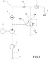
- the discharge valve 12 is a three-way, two-position valve with differential hydraulic control.
- Said valve 12 has a main inlet 12a connected to the hydraulic circuit of the machine M between the one-way valve 10 and the brewing assembly 1, a first control inlet 12b connected between the outlet of the pump 3 and the one-way valve 10 and an outlet 12c communicating with the drainage or discharge recipient 11.
- the main inlet 12a can also act as a second control inlet 12d.
- the arrangement is such that, once the pump 3 has been activated to prepare a beverage, the hydraulic-control discharge valve 12 switches from the open condition to the closed condition before the one-way valve 10 opens.
- the discharge valve 12 works on the basis of control by pressure difference. This was developed on the basis of experimental observations of the ratio between the pressure in the outlet branch of the pump and the pressure in the brewing chamber: this ratio differs substantially between operational and non-operational conditions. It has also been observed that said ratio does not however vary significantly while beverages are being dispensed and therefore remains approximately unchanged as the back pressure exerted by the precursors of said beverages varies.
- the pump 3 is deactivated and the discharge valve 12 switches back to the open condition.
- the hydraulic-control valve 12 has a simplified structure, and requires neither a solenoid nor a dedicated electrical line to be controlled.
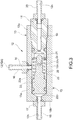
- Figure 3 shows an embodiment of the hydraulic-control discharge valve 12 useable in the machine M in Figure 2 .
- the valve 12 according to Figure 3 includes a hollow body that, in the example embodiment shown, is formed by two elements 13 and 14 that are joined together using a threaded coupling.
- the element 13 has an essentially tubular wall 13a, one extremity of which is screwed to the element 14. At the opposite extremity, the tubular wall 13a is connected to a transverse end wall 13b.
- connection 18 is fitted in a fluid-tight manner, the central passage of same being the first control inlet 12b of the valve 12.
- the element 14 has an axial central passage 19, and a connection 20 is fitted to one extremity of same in a fluid-tight manner, the central passage of which is the outlet 12c of the discharge valve.
- a valve seat 21 is formed in the element 14 at the extremity of the passage 19 opposite the connection 20.
- a piston 23 is mounted axially moveably and in a fluid-tight manner inside said chamber, dividing same into two chamber portions 22a and 22b, same being sealingly separated from one another and in communication with the main and control inlet 12a, 12d and, respectively, with the control inlet 12b.
- the piston 23 bears a plug 24 designed to cooperate with the valve seat 21 to control communication between the main inlet 12a and the outlet 12c.
- a helical spring 25 is arranged in the portion 22a of the chamber 22, between the piston 23 and the element 14 of the body of the discharge valve. This spring 25 acts on the piston 23, tending to move said piston and the plug 24 away from the valve seat 21.
- the discharge valve 12 is normally open, i.e. it normally adopts the arrangement shown in Figure 3 , in which the plug 24 is removed from the valve seat 21 and consequently the main inlet 12a is in communication with the outlet 12c.
- pressurized water reaches the control inlet 12b of the discharge valve 12, causing the piston 23 to move towards the element 14 of the body of the discharge valve 12. This is possible because the intervention pressure required to move the piston 23 is less than the threshold pressure of the one-way hydraulic valve 10, which is for example 1.5 bar.
- the plug 24 then closes the valve seat 21, disconnecting the main inlet 12a from the outlet 12c, before the one-way valve 10 opens.
- the water flow generated by the pump 3 and heated by the device 9 reaches the brewing assembly 1, in which a quantity of a substance used to prepare the beverage has been placed in a known manner, potentially pre-packaged in a capsule or similar.
- the beverage is then gradually dispensed into the collecting recipient 2.
- the one-way valve 10 remains open, enabling the hydraulic circuit to be emptied upstream of same, and the beverage continues to flow from the brewing assembly 1 towards the cup 2.
- the pressures in the chambers 22b and 22a of the discharge valve 12 fall until the pressure of the spring 25 combined with the pressure in the chamber 22 matches the pressure in the chamber 22b, enabling the valve to reopen.
- This operating mode is typical of a differential-pressure control valve.
- the plug 4 is no longer in contact with the seat 21, and the water contained in the hydraulic circuit of the machine between the brewing assembly 1 and the one-way valve 10 can then be discharged through the differential valve 12 into the drain or drip tray 11.
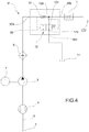
- the one-way valve 10 and the hydraulic-control discharge valve 12 can be built into a single valve assembly, indicated using reference sign 30 in Figures 4 and 5 .
- the parts and elements in said figures that have already been described are indicated using the same reference signs as used previously.
- the valve assembly 30 has an inlet 30a that is connected externally to the hydraulic circuit of the machine M between the outlet of the pump 3 and the brewing assembly 1, communicating inside said assembly with the inlet of the one-way valve 10 and with the control inlet 12b of the discharge valve 12.
- the valve assembly 30 also has an inlet/outlet 30b connected externally to the brewing assembly 1, and communicating internally with the outlet of the one-way valve 10 and with the main and control inlet 12a, 12d of the discharge valve 12.
- valve assembly 30 has an outlet 30c that communicates with the discharge recipient 11 and that, inside said assembly 30, communicates with the outlet 12c of the discharge valve 12.
- FIG 5 shows an embodiment of the valve assembly 30 shown schematically in Figure 4 .
- the one-way valve 10 is in fact built into the discharge valve 12.
- the piston 23 is formed by two hollow bodies 26 and 27, which are joined together, for example by means of a threaded coupling.
- An axial passage 26a is formed in the body 26, which is oriented towards the control inlet 12b of the discharge valve 12 or the inlet 30a of the valve assembly 30, said axial passage 26a being in communication with said inlet 12b (30a) and being able to be brought into communication with an adjacent cavity 26b controlled by a plug 28 cooperating with an associated seat 29 formed between the passage 26a and the cavity 26b.
- the plug 28 is associated with a helical spring 31 that tends to press same towards the seat 29.
- the plug 28, the related seat 29 and the spring 31 together form the one-way valve indicated using reference sign 10 in Figure 4 .
- the cavity 26b communicates permanently with the portion 22a of the chamber 22 through one or more passages 32 formed in the body 27.
- valve assembly 30 in Figure 5 is shown in the condition in which the discharge valve 12 (21, 24) has already been closed, but the non-return valve 10 has not yet been opened, this phase immediately preceding the triggering of the flow of pressurized hot water to the brewing assembly 1 of the machine.
- valve assembly 30 makes it possible to significantly simplify the necessary hydraulic connections.
Landscapes
- Engineering & Computer Science (AREA)
- Food Science & Technology (AREA)
- Apparatus For Making Beverages (AREA)
- Check Valves (AREA)
Description
- This invention relates to a machine for preparing beverages, in particular espresso coffee. More specifically, the invention relates to a machine having a hydraulic circuit including
- a brewing assembly,
- a water tank, a pump having an inlet connected to said tank and an outlet connected to the brewing assembly,
- a normally closed, one-way, hydraulic valve interposed between the pump and the brewing assembly to allow a flow of water to the brewing assembly when the pressure of the water outputted from the pump exceeds a predetermined threshold,
- electric heating means for heating the water outputted by the pump, and
- a normally open discharge valve having an inlet connected between the one-way hydraulic valve and the brewing assembly, and designed to adopt an open condition and a closed condition, in which it allows and prevents, respectively, a flow of fluid from the brewing assembly towards a discharge environment.
- A machine of this type is described in Italian patent application
TO2014A001002, filed on 18 December 2014 WO 02/058523 A1 - The document
CN 201719074 U discloses a two position valve with differential hydraulic driving. - In this existing machine, the discharge valve is a normally open two-way, two-position solenoid valve. When in operation, once the beverage has been dispensed, the hydraulic circuit of the machine is emptied through said solenoid valve, which is excited by the control unit of the machine and opens a discharge passage that enables the pressurized water between the brewing assembly and the one-way valve to flow into a collecting recipient, such as a drip tray.
- The known solution described above works very well, but is somewhat expensive because the discharge valve is a solenoid valve, which has to be connected to the control unit of the machine by means of a suitable electrical control line.
- The cost of the solenoid for controlling a hydraulic plug depends on the quality of the copper required to make same, which in turn depends on the intensity of the force same is required to supply. To reduce the cost of this component, it is known to reduce the hydraulic shapes inside the valve, but this has the drawback of potential fouling and blocking of the valve during the service life of same.
- One object of the present invention is to make such a machine for preparing beverages that is cheap and incorporates simplified electrical wiring.
- This and other objects are achieved according to the invention with a machine of the type specified above, characterized in that the discharge valve is a three-way, two-position valve with differential hydraulic control, having a main inlet coupled with said hydraulic circuit between the one-way valve and the brewing assembly, first and second control inlets connected between the outlet of the pump and said one-way valve and, respectively, between the one-way valve and the brewing assembly and an outlet communicating with said discharge environment;
the arrangement being such that after the pump is activated for preparing a beverage, the discharge valve switches from the open condition to the closed condition before said one-way valve opens, and when the pump is deactivated after the beverage has been dispensed, the discharge valve switches back to the open condition. - In one embodiment, the one-way valve and the discharge valve are suitably built into a single three-way valve assembly.
- In particular, the one-way valve may be suitably built into the hydraulic-control discharge valve.
- Further characteristics and advantages of the invention are set out in the detailed description below, provided purely as a non limiting example, with reference to the attached drawings, in which:
-
Figure 1 is a schematic view of a machine for preparing beverages according to the prior art, -
Figure 2 is a schematic view of a machine for preparing beverages according to the present invention, -
Figure 3 is an axial cross section of a hydraulic-control discharge valve useable in accordance with the present invention, -
Figure 4 is a schematic view of an alternative embodiment of a machine for preparing beverages according to the invention, and -
Figure 5 is an axial cross section of an embodiment of an integrated valve assembly useable in a machine according to the present invention. - In
Figure 1 , reference sign M is used to indicate, as a whole, a machine for preparing beverages according to the prior art. Said machine M includes a hydraulic circuit including abrewing assembly 1 that is hydraulically substantially equivalent to a choke for dispensing a beverage into a collectingcontainer 2, such as a cup. - An
electric pump 3 has an inlet connected to awater tank 4 via anaspiration pipe 5 which may be fitted with aflow meter 6, for example a turbine flow meter, to provide electrical signals (pulses) indicating the flow rate of the water aspirated by the pump. - The
pump 3 may be a vibrating electric pump or a pump driven by anelectric motor 8 of a known type. - The pressurized water outputted by the
pump 3 then reaches an electric heating device orboiler 9, and therefrom continues towards thebrewing assembly 1. - A one-way
hydraulic valve 10 designed to enable water to flow towards said brewing assembly when the pressure of the water coming from thepump 3 exceeds a predetermined threshold value, such as 2 bar, is positioned between theheating device 9 and thebrewing assembly 1. -
Reference sign 12 is used to indicate a discharge valve, in the form of a two-way, two-position solenoid valve, with the inlet connected between the outlet of the one-way valve 10 and the inlet of thebrewing assembly 1, and the outlet connected to adrainage recipient 11, such as the drip tray or box usually supplied with a coffee machine. - In the machine according to the prior art described above, the
discharge solenoid valve 12 is a somewhat costly component. Said valve includes anexcitation solenoid 12a that has to be connected to a control unit (not shown) of the machine M using a suitable electrical line. - A substantial saving can be made with a solution according to the present invention, a first embodiment of which is described below with reference to
Figure 2 . The parts and elements in said figure that have already been described are indicated using the same reference signs as used previously. - In the machine M according to
Figure 2 , thedischarge valve 12 is a three-way, two-position valve with differential hydraulic control. Saidvalve 12 has amain inlet 12a connected to the hydraulic circuit of the machine M between the one-way valve 10 and thebrewing assembly 1, afirst control inlet 12b connected between the outlet of thepump 3 and the one-way valve 10 and anoutlet 12c communicating with the drainage ordischarge recipient 11. As described more clearly below, when in operation, themain inlet 12a can also act as asecond control inlet 12d. - The arrangement is such that, once the
pump 3 has been activated to prepare a beverage, the hydraulic-control discharge valve 12 switches from the open condition to the closed condition before the one-way valve 10 opens. - The
discharge valve 12 works on the basis of control by pressure difference. This was developed on the basis of experimental observations of the ratio between the pressure in the outlet branch of the pump and the pressure in the brewing chamber: this ratio differs substantially between operational and non-operational conditions. It has also been observed that said ratio does not however vary significantly while beverages are being dispensed and therefore remains approximately unchanged as the back pressure exerted by the precursors of said beverages varies. - Once the beverage has been dispensed, the
pump 3 is deactivated and thedischarge valve 12 switches back to the open condition. - The hydraulic-
control valve 12 has a simplified structure, and requires neither a solenoid nor a dedicated electrical line to be controlled. -
Figure 3 shows an embodiment of the hydraulic-control discharge valve 12 useable in the machine M inFigure 2 . - The
valve 12 according toFigure 3 includes a hollow body that, in the example embodiment shown, is formed by twoelements - The
element 13 has an essentiallytubular wall 13a, one extremity of which is screwed to theelement 14. At the opposite extremity, thetubular wall 13a is connected to atransverse end wall 13b. - There is an opening 15 in the intermediate portion of the
tubular wall 13a, into which aninlet connection 16 is fitted in a fluid-tight manner, the central passage of same being themain inlet 12a and the second control inlet 12d of thevalve 12. - There is a through
hole 17 in the central portion of theend wall 13b, into which aconnection 18 is fitted in a fluid-tight manner, the central passage of same being thefirst control inlet 12b of thevalve 12. - The
element 14 has an axialcentral passage 19, and aconnection 20 is fitted to one extremity of same in a fluid-tight manner, the central passage of which is theoutlet 12c of the discharge valve. - A
valve seat 21 is formed in theelement 14 at the extremity of thepassage 19 opposite theconnection 20. - There is a chamber, indicated as a whole with
reference sign 22, between theelements piston 23 is mounted axially moveably and in a fluid-tight manner inside said chamber, dividing same into twochamber portions control inlet control inlet 12b. - In the portion oriented towards the
element 14, thepiston 23 bears aplug 24 designed to cooperate with thevalve seat 21 to control communication between themain inlet 12a and theoutlet 12c. - A
helical spring 25 is arranged in theportion 22a of thechamber 22, between thepiston 23 and theelement 14 of the body of the discharge valve. Thisspring 25 acts on thepiston 23, tending to move said piston and theplug 24 away from thevalve seat 21. - As indicated above, the
discharge valve 12 is normally open, i.e. it normally adopts the arrangement shown inFigure 3 , in which theplug 24 is removed from thevalve seat 21 and consequently themain inlet 12a is in communication with theoutlet 12c. - Once the
pump 3 has been activated, to prepare a beverage, pressurized water reaches thecontrol inlet 12b of thedischarge valve 12, causing thepiston 23 to move towards theelement 14 of the body of thedischarge valve 12. This is possible because the intervention pressure required to move thepiston 23 is less than the threshold pressure of the one-wayhydraulic valve 10, which is for example 1.5 bar. Theplug 24 then closes thevalve seat 21, disconnecting themain inlet 12a from theoutlet 12c, before the one-way valve 10 opens. - The sequential closure of the
discharge valve 12 followed by the one-way valve 10 can be ensured by properly dimensioning thespring 25 of the discharge valve. - Once the
discharge valve 12 has been closed and the one-way valve 10 has been opened, the water flow generated by thepump 3 and heated by thedevice 9 reaches thebrewing assembly 1, in which a quantity of a substance used to prepare the beverage has been placed in a known manner, potentially pre-packaged in a capsule or similar. The beverage is then gradually dispensed into the collectingrecipient 2. - Once the beverage has been dispensed and the
pump 3 has been deactivated, the one-way valve 10 remains open, enabling the hydraulic circuit to be emptied upstream of same, and the beverage continues to flow from thebrewing assembly 1 towards thecup 2. The pressures in thechambers spring 25 combined with the pressure in thechamber 22 matches the pressure in thechamber 22b, enabling the valve to reopen. This operating mode is typical of a differential-pressure control valve. - Once opening has been completed, the
plug 4 is no longer in contact with theseat 21, and the water contained in the hydraulic circuit of the machine between thebrewing assembly 1 and the one-way valve 10 can then be discharged through thedifferential valve 12 into the drain ordrip tray 11. - Advantageously, as shown schematically in
Figure 4 , the one-way valve 10 and the hydraulic-control discharge valve 12 can be built into a single valve assembly, indicated usingreference sign 30 inFigures 4 and5 . The parts and elements in said figures that have already been described are indicated using the same reference signs as used previously. - With reference to
Figure 4 , thevalve assembly 30 has aninlet 30a that is connected externally to the hydraulic circuit of the machine M between the outlet of thepump 3 and thebrewing assembly 1, communicating inside said assembly with the inlet of the one-way valve 10 and with thecontrol inlet 12b of thedischarge valve 12. Thevalve assembly 30 also has an inlet/outlet 30b connected externally to thebrewing assembly 1, and communicating internally with the outlet of the one-way valve 10 and with the main andcontrol inlet discharge valve 12. - Finally, the
valve assembly 30 has anoutlet 30c that communicates with thedischarge recipient 11 and that, inside saidassembly 30, communicates with theoutlet 12c of thedischarge valve 12. -
Figure 5 shows an embodiment of thevalve assembly 30 shown schematically inFigure 4 . In said embodiment, the one-way valve 10 is in fact built into thedischarge valve 12. - In the embodiment shown in
Figure 5 , thepiston 23 is formed by twohollow bodies - An
axial passage 26a is formed in thebody 26, which is oriented towards thecontrol inlet 12b of thedischarge valve 12 or theinlet 30a of thevalve assembly 30, saidaxial passage 26a being in communication with saidinlet 12b (30a) and being able to be brought into communication with anadjacent cavity 26b controlled by aplug 28 cooperating with an associatedseat 29 formed between thepassage 26a and thecavity 26b. - The
plug 28 is associated with ahelical spring 31 that tends to press same towards theseat 29. - The
plug 28, therelated seat 29 and thespring 31 together form the one-way valve indicated usingreference sign 10 inFigure 4 . - The
cavity 26b communicates permanently with theportion 22a of thechamber 22 through one ormore passages 32 formed in thebody 27. - The operating mode of the
valve assembly 30 inFigure 5 can be immediately understood from the above description. - The
valve assembly 30 inFigure 5 is shown in the condition in which the discharge valve 12 (21, 24) has already been closed, but thenon-return valve 10 has not yet been opened, this phase immediately preceding the triggering of the flow of pressurized hot water to thebrewing assembly 1 of the machine. - In the embodiments shown in
Figures 4 and5 , thevalve assembly 30 makes it possible to significantly simplify the necessary hydraulic connections. - Naturally, notwithstanding the principle of the invention, the means of implementation and the specific embodiments may vary greatly from that described and illustrated purely by way of a non-limiting example, without thereby moving outside the scope of the invention as defined in the attached claims.
Claims (5)
- Machine (M) for preparing beverages, in particular espresso coffee, comprising a hydraulic circuit including
a brewing assembly (1),
a water tank (4),
a pump (3) having an inlet connected to said tank (4) and the outlet coupled with the brewing assembly (1),
a normally closed, one-way hydraulic valve (10) interposed between the pump (3) and the brewing assembly (1) to allow a flow of water to the brewing assembly (1) when the pressure of the water outputted from the pump (3) exceeds a predetermined threshold,
heating means (9) for heating the water outputted by the pump (3), and
a normally open discharge valve (12) having an inlet (12a) connected between said one-way hydraulic valve (10) and the brewing assembly (1), designed to adopt an open condition and a closed condition, in which it allows and prevents, respectively, a flow of fluid from said inlet (12a) towards a discharge environment (11);
the machine (M) being characterized in that
the discharge valve (12) is a three-way, two-position valve with differential hydraulic control, having a main inlet (12a) coupled with said hydraulic circuit between the one-way hydraulic valve (10) and the brewing assembly (1), first and second control inlets (12b; 12d, 12a) connected between the outlet of the pump (3) and the one-way hydraulic valve (10) and, respectively, between the one-way hydraulic valve (10) and the brewing assembly (1), and an outlet (12c) communicating with said discharge environment (11);
the arrangement being such that after the pump (3) is activated for preparing the beverage, the discharge valve (12) switches from the open condition to the closed condition before the one-way hydraulic valve (10) opens, and after the pump (3) is deactivated when the beverage has been dispensed, the discharge valve (12) switches back to the open condition. - Machine according to Claim 1, wherein said one-way hydraulic valve (10) and the discharge valve (12) are integrated in a single three-way valve assembly (30) having
an inlet (30a) connected externally to said hydraulic circuit, between the outlet of the pump (3) and the brewing assembly (1), and communicating internally with the inlet of the one-way valve hydraulic (10) as well as with the first control inlet (12b) of the discharge valve (12),
an inlet/outlet (30b) connected externally to the brewing assembly (1), and communicating internally with the outlet of the one-way hydraulic valve (10) and the main inlet (12a) of the discharge valve (12), and
an outlet (30c) communicating with said discharge environment (11). - Machine according to Claim 1 or Claim 2, wherein the discharge valve (12) comprises a hollow body (13, 14) in which there are provided said main inlet (12a; 15, 16), the first control inlet (12b; 17, 18) and the outlet (12c; 20), and in which there is defined a chamber (22) communicating with the main inlet (12a; 15, 16) and the first control inlet (12b; 17, 18) and which is able to communicate with the outlet (12c; 20) through a valve seat (21);
between the control inlet (12b; 17, 18) and the main inlet (12a; 15, 16) in said chamber (22) there being movably mounted, in a liquid-tight manner, a piston (23) carrying a plug (24) adapted to cooperate with said valve seat (21) for controlling the communication between the main inlet (12a; 15, 16) and the outlet (12c; 20); said piston (23) having associated resilient means (25) tending to displace the plug (24) away from said valve seat (21). - Machine according to Claims 2 and 3, wherein said one-way hydraulic valve (10) is built into the discharge valve (12).
- Machine according to Claim 4, wherein in said piston (23; 26, 27) there is defined a cavity (26b) communicating permanently with the main inlet (12a; 15, 16) of the discharge valve (12) and in which there is defined a further valve seat (29) through which said cavity (26b) can communicate with the control inlet (12b; 17, 18) of the discharge valve (12); in said cavity (26b) there being movably mounted a further plug (28) cooperating with said further valve seat (29) for controlling the communication between the first control inlet (12b) and the main inlet (12a) which in operation can perform the function of said inlet/outlet (30b) and second control inlet (12d); said further plug (28) being associated with further resilient means (31) tending to keep it in engagement against said further valve seat (29).
Applications Claiming Priority (2)
| Application Number | Priority Date | Filing Date | Title |
|---|---|---|---|
| ITTO20150079 | 2015-02-04 | ||
| PCT/IB2016/050540 WO2016125085A1 (en) | 2015-02-04 | 2016-02-03 | Machine for preparing beverages, in particular espresso coffee, and valve assembly usable in such a machine |
Publications (2)
| Publication Number | Publication Date |
|---|---|
| EP3253265A1 EP3253265A1 (en) | 2017-12-13 |
| EP3253265B1 true EP3253265B1 (en) | 2018-12-05 |
Family
ID=52815188
Family Applications (1)
| Application Number | Title | Priority Date | Filing Date |
|---|---|---|---|
| EP16712474.2A Active EP3253265B1 (en) | 2015-02-04 | 2016-02-03 | Machine for preparing beverages, in particular espresso coffee, and valve assembly usable in such a machine |
Country Status (3)
| Country | Link |
|---|---|
| EP (1) | EP3253265B1 (en) |
| CN (1) | CN107405023B (en) |
| WO (1) | WO2016125085A1 (en) |
Families Citing this family (2)
| Publication number | Priority date | Publication date | Assignee | Title |
|---|---|---|---|---|
| EP3420863A1 (en) | 2017-06-28 | 2019-01-02 | Koninklijke Philips N.V. | Switching valve and beverage making device comprising a switching valve |
| CN112656216B (en) * | 2020-12-21 | 2022-06-24 | 中山卡士电器有限公司 | A tea washing mechanism of an automatic tea maker |
Family Cites Families (7)
| Publication number | Priority date | Publication date | Assignee | Title |
|---|---|---|---|---|
| CH694265A5 (en) * | 2001-01-24 | 2004-10-29 | Monodor Sa | Water injection device for an apparatus for the preparation of a beverage from a capsule containing the product to be extracted. |
| EP1804630B1 (en) * | 2004-09-20 | 2008-08-20 | Koninklijke Philips Electronics N.V. | A beverage-making device comprising a brewing chamber and pressure release means |
| CN201719074U (en) * | 2010-05-26 | 2011-01-26 | 应雄峰 | Pressure release valve device of coffee machine |
| EP2397054A1 (en) * | 2010-06-15 | 2011-12-21 | Jura Elektroapparate AG | Brewing device with a coffee reheater |
| CN102599819B (en) * | 2012-04-11 | 2013-11-27 | 浙江酷菲尔电器有限公司 | Pressure-relief return valve for coffee maker |
| CN203378976U (en) * | 2013-08-15 | 2014-01-08 | 慈溪远志工业产品设计有限公司 | Italian coffee machine with water level indicating function |
| CN203723929U (en) * | 2014-03-11 | 2014-07-23 | 宁波凯波集团有限公司 | Capsule beverage brewing device |
-
2016
- 2016-02-03 CN CN201680018587.6A patent/CN107405023B/en active Active
- 2016-02-03 WO PCT/IB2016/050540 patent/WO2016125085A1/en not_active Ceased
- 2016-02-03 EP EP16712474.2A patent/EP3253265B1/en active Active
Non-Patent Citations (1)
| Title |
|---|
| None * |
Also Published As
| Publication number | Publication date |
|---|---|
| EP3253265A1 (en) | 2017-12-13 |
| WO2016125085A1 (en) | 2016-08-11 |
| CN107405023A (en) | 2017-11-28 |
| CN107405023B (en) | 2019-12-17 |
Similar Documents
| Publication | Publication Date | Title |
|---|---|---|
| EP3310222B1 (en) | Machine for preparing beverages, in particular espresso coffee, and valve and valve unit for use therein | |
| US8931399B2 (en) | Brewing apparatus with a drainage valve | |
| CN201164370Y (en) | Coffee machine | |
| EP3490416B1 (en) | A machine for preparing beverages, in particular espresso coffee, a valve and a valve unit that can be used in said machine | |
| EP2369963B1 (en) | Infusion unit | |
| EP3313243B1 (en) | Beverage producing machine | |
| RU2008107329A (en) | HYDRAULIC CIRCUIT FOR MACHINES FOR PREPARATION OF FAST INSTANT DRINKS, BYPASS AND PROTECT VALVE FOR INDICATED CIRCUIT AND METHOD FOR PREPARING FAST INSTANT DRINKS | |
| EP3226729B1 (en) | Machine for the preparation of beverages, in particular espresso coffee | |
| EP3102317B1 (en) | Carbonation unit | |
| JP5198064B2 (en) | Beverage preparation device having brew chamber and pressure release means | |
| EP4487738B1 (en) | Milk line cleaning system for coffee maker | |
| EP3253265A1 (en) | Machine for preparing beverages, in particular espresso coffee, and valve assembly usable in such a machine | |
| CN110063652A (en) | The water circuit system of drink-extracting equipment and the flow divider for being applicable in the water circuit system | |
| WO2012004660A1 (en) | Infusion unit | |
| WO2012049596A1 (en) | Capsule closure device for a coffee capsule machine | |
| CN201624525U (en) | Beverage brewing device | |
| CN223627339U (en) | Beverage machine and brewing device | |
| RU2829723C2 (en) | Draining rinsing water from brewing chamber of beverage preparation device | |
| CN122030781A (en) | Beverage machine and brewing device | |
| HK1142504B (en) | Brewing apparatus with a drainage valve |
Legal Events
| Date | Code | Title | Description |
|---|---|---|---|
| STAA | Information on the status of an ep patent application or granted ep patent |
Free format text: STATUS: THE INTERNATIONAL PUBLICATION HAS BEEN MADE |
|
| PUAI | Public reference made under article 153(3) epc to a published international application that has entered the european phase |
Free format text: ORIGINAL CODE: 0009012 |
|
| STAA | Information on the status of an ep patent application or granted ep patent |
Free format text: STATUS: REQUEST FOR EXAMINATION WAS MADE |
|
| 17P | Request for examination filed |
Effective date: 20170804 |
|
| AK | Designated contracting states |
Kind code of ref document: A1 Designated state(s): AL AT BE BG CH CY CZ DE DK EE ES FI FR GB GR HR HU IE IS IT LI LT LU LV MC MK MT NL NO PL PT RO RS SE SI SK SM TR |
|
| AX | Request for extension of the european patent |
Extension state: BA ME |
|
| DAV | Request for validation of the european patent (deleted) | ||
| DAX | Request for extension of the european patent (deleted) | ||
| GRAP | Despatch of communication of intention to grant a patent |
Free format text: ORIGINAL CODE: EPIDOSNIGR1 |
|
| STAA | Information on the status of an ep patent application or granted ep patent |
Free format text: STATUS: GRANT OF PATENT IS INTENDED |
|
| INTG | Intention to grant announced |
Effective date: 20180612 |
|
| GRAS | Grant fee paid |
Free format text: ORIGINAL CODE: EPIDOSNIGR3 |
|
| GRAA | (expected) grant |
Free format text: ORIGINAL CODE: 0009210 |
|
| STAA | Information on the status of an ep patent application or granted ep patent |
Free format text: STATUS: THE PATENT HAS BEEN GRANTED |
|
| AK | Designated contracting states |
Kind code of ref document: B1 Designated state(s): AL AT BE BG CH CY CZ DE DK EE ES FI FR GB GR HR HU IE IS IT LI LT LU LV MC MK MT NL NO PL PT RO RS SE SI SK SM TR |
|
| REG | Reference to a national code |
Ref country code: GB Ref legal event code: FG4D |
|
| REG | Reference to a national code |
Ref country code: CH Ref legal event code: EP |
|
| REG | Reference to a national code |
Ref country code: AT Ref legal event code: REF Ref document number: 1071983 Country of ref document: AT Kind code of ref document: T Effective date: 20181215 |
|
| REG | Reference to a national code |
Ref country code: IE Ref legal event code: FG4D |
|
| REG | Reference to a national code |
Ref country code: DE Ref legal event code: R096 Ref document number: 602016007867 Country of ref document: DE |
|
| REG | Reference to a national code |
Ref country code: NL Ref legal event code: MP Effective date: 20181205 |
|
| REG | Reference to a national code |
Ref country code: AT Ref legal event code: MK05 Ref document number: 1071983 Country of ref document: AT Kind code of ref document: T Effective date: 20181205 |
|
| REG | Reference to a national code |
Ref country code: LT Ref legal event code: MG4D |
|
| PG25 | Lapsed in a contracting state [announced via postgrant information from national office to epo] |
Ref country code: FI Free format text: LAPSE BECAUSE OF FAILURE TO SUBMIT A TRANSLATION OF THE DESCRIPTION OR TO PAY THE FEE WITHIN THE PRESCRIBED TIME-LIMIT Effective date: 20181205 Ref country code: BG Free format text: LAPSE BECAUSE OF FAILURE TO SUBMIT A TRANSLATION OF THE DESCRIPTION OR TO PAY THE FEE WITHIN THE PRESCRIBED TIME-LIMIT Effective date: 20190305 Ref country code: HR Free format text: LAPSE BECAUSE OF FAILURE TO SUBMIT A TRANSLATION OF THE DESCRIPTION OR TO PAY THE FEE WITHIN THE PRESCRIBED TIME-LIMIT Effective date: 20181205 Ref country code: AT Free format text: LAPSE BECAUSE OF FAILURE TO SUBMIT A TRANSLATION OF THE DESCRIPTION OR TO PAY THE FEE WITHIN THE PRESCRIBED TIME-LIMIT Effective date: 20181205 Ref country code: LV Free format text: LAPSE BECAUSE OF FAILURE TO SUBMIT A TRANSLATION OF THE DESCRIPTION OR TO PAY THE FEE WITHIN THE PRESCRIBED TIME-LIMIT Effective date: 20181205 Ref country code: LT Free format text: LAPSE BECAUSE OF FAILURE TO SUBMIT A TRANSLATION OF THE DESCRIPTION OR TO PAY THE FEE WITHIN THE PRESCRIBED TIME-LIMIT Effective date: 20181205 Ref country code: NO Free format text: LAPSE BECAUSE OF FAILURE TO SUBMIT A TRANSLATION OF THE DESCRIPTION OR TO PAY THE FEE WITHIN THE PRESCRIBED TIME-LIMIT Effective date: 20190305 |
|
| PG25 | Lapsed in a contracting state [announced via postgrant information from national office to epo] |
Ref country code: AL Free format text: LAPSE BECAUSE OF FAILURE TO SUBMIT A TRANSLATION OF THE DESCRIPTION OR TO PAY THE FEE WITHIN THE PRESCRIBED TIME-LIMIT Effective date: 20181205 Ref country code: GR Free format text: LAPSE BECAUSE OF FAILURE TO SUBMIT A TRANSLATION OF THE DESCRIPTION OR TO PAY THE FEE WITHIN THE PRESCRIBED TIME-LIMIT Effective date: 20190306 Ref country code: RS Free format text: LAPSE BECAUSE OF FAILURE TO SUBMIT A TRANSLATION OF THE DESCRIPTION OR TO PAY THE FEE WITHIN THE PRESCRIBED TIME-LIMIT Effective date: 20181205 Ref country code: SE Free format text: LAPSE BECAUSE OF FAILURE TO SUBMIT A TRANSLATION OF THE DESCRIPTION OR TO PAY THE FEE WITHIN THE PRESCRIBED TIME-LIMIT Effective date: 20181205 |
|
| PG25 | Lapsed in a contracting state [announced via postgrant information from national office to epo] |
Ref country code: NL Free format text: LAPSE BECAUSE OF FAILURE TO SUBMIT A TRANSLATION OF THE DESCRIPTION OR TO PAY THE FEE WITHIN THE PRESCRIBED TIME-LIMIT Effective date: 20181205 |
|
| PG25 | Lapsed in a contracting state [announced via postgrant information from national office to epo] |
Ref country code: CZ Free format text: LAPSE BECAUSE OF FAILURE TO SUBMIT A TRANSLATION OF THE DESCRIPTION OR TO PAY THE FEE WITHIN THE PRESCRIBED TIME-LIMIT Effective date: 20181205 Ref country code: PT Free format text: LAPSE BECAUSE OF FAILURE TO SUBMIT A TRANSLATION OF THE DESCRIPTION OR TO PAY THE FEE WITHIN THE PRESCRIBED TIME-LIMIT Effective date: 20190405 Ref country code: ES Free format text: LAPSE BECAUSE OF FAILURE TO SUBMIT A TRANSLATION OF THE DESCRIPTION OR TO PAY THE FEE WITHIN THE PRESCRIBED TIME-LIMIT Effective date: 20181205 Ref country code: PL Free format text: LAPSE BECAUSE OF FAILURE TO SUBMIT A TRANSLATION OF THE DESCRIPTION OR TO PAY THE FEE WITHIN THE PRESCRIBED TIME-LIMIT Effective date: 20181205 |
|
| PG25 | Lapsed in a contracting state [announced via postgrant information from national office to epo] |
Ref country code: EE Free format text: LAPSE BECAUSE OF FAILURE TO SUBMIT A TRANSLATION OF THE DESCRIPTION OR TO PAY THE FEE WITHIN THE PRESCRIBED TIME-LIMIT Effective date: 20181205 Ref country code: SK Free format text: LAPSE BECAUSE OF FAILURE TO SUBMIT A TRANSLATION OF THE DESCRIPTION OR TO PAY THE FEE WITHIN THE PRESCRIBED TIME-LIMIT Effective date: 20181205 Ref country code: IS Free format text: LAPSE BECAUSE OF FAILURE TO SUBMIT A TRANSLATION OF THE DESCRIPTION OR TO PAY THE FEE WITHIN THE PRESCRIBED TIME-LIMIT Effective date: 20190405 Ref country code: RO Free format text: LAPSE BECAUSE OF FAILURE TO SUBMIT A TRANSLATION OF THE DESCRIPTION OR TO PAY THE FEE WITHIN THE PRESCRIBED TIME-LIMIT Effective date: 20181205 Ref country code: SM Free format text: LAPSE BECAUSE OF FAILURE TO SUBMIT A TRANSLATION OF THE DESCRIPTION OR TO PAY THE FEE WITHIN THE PRESCRIBED TIME-LIMIT Effective date: 20181205 |
|
| REG | Reference to a national code |
Ref country code: DE Ref legal event code: R097 Ref document number: 602016007867 Country of ref document: DE |
|
| REG | Reference to a national code |
Ref country code: CH Ref legal event code: PL |
|
| PLBE | No opposition filed within time limit |
Free format text: ORIGINAL CODE: 0009261 |
|
| STAA | Information on the status of an ep patent application or granted ep patent |
Free format text: STATUS: NO OPPOSITION FILED WITHIN TIME LIMIT |
|
| PG25 | Lapsed in a contracting state [announced via postgrant information from national office to epo] |
Ref country code: LU Free format text: LAPSE BECAUSE OF NON-PAYMENT OF DUE FEES Effective date: 20190203 Ref country code: SI Free format text: LAPSE BECAUSE OF FAILURE TO SUBMIT A TRANSLATION OF THE DESCRIPTION OR TO PAY THE FEE WITHIN THE PRESCRIBED TIME-LIMIT Effective date: 20181205 Ref country code: MC Free format text: LAPSE BECAUSE OF FAILURE TO SUBMIT A TRANSLATION OF THE DESCRIPTION OR TO PAY THE FEE WITHIN THE PRESCRIBED TIME-LIMIT Effective date: 20181205 Ref country code: DK Free format text: LAPSE BECAUSE OF FAILURE TO SUBMIT A TRANSLATION OF THE DESCRIPTION OR TO PAY THE FEE WITHIN THE PRESCRIBED TIME-LIMIT Effective date: 20181205 |
|
| 26N | No opposition filed |
Effective date: 20190906 |
|
| REG | Reference to a national code |
Ref country code: BE Ref legal event code: MM Effective date: 20190228 |
|
| REG | Reference to a national code |
Ref country code: IE Ref legal event code: MM4A |
|
| PG25 | Lapsed in a contracting state [announced via postgrant information from national office to epo] |
Ref country code: LI Free format text: LAPSE BECAUSE OF NON-PAYMENT OF DUE FEES Effective date: 20190228 Ref country code: CH Free format text: LAPSE BECAUSE OF NON-PAYMENT OF DUE FEES Effective date: 20190228 |
|
| PG25 | Lapsed in a contracting state [announced via postgrant information from national office to epo] |
Ref country code: IE Free format text: LAPSE BECAUSE OF NON-PAYMENT OF DUE FEES Effective date: 20190203 |
|
| PG25 | Lapsed in a contracting state [announced via postgrant information from national office to epo] |
Ref country code: BE Free format text: LAPSE BECAUSE OF NON-PAYMENT OF DUE FEES Effective date: 20190228 |
|
| PG25 | Lapsed in a contracting state [announced via postgrant information from national office to epo] |
Ref country code: TR Free format text: LAPSE BECAUSE OF FAILURE TO SUBMIT A TRANSLATION OF THE DESCRIPTION OR TO PAY THE FEE WITHIN THE PRESCRIBED TIME-LIMIT Effective date: 20181205 |
|
| PG25 | Lapsed in a contracting state [announced via postgrant information from national office to epo] |
Ref country code: MT Free format text: LAPSE BECAUSE OF NON-PAYMENT OF DUE FEES Effective date: 20190203 |
|
| PG25 | Lapsed in a contracting state [announced via postgrant information from national office to epo] |
Ref country code: CY Free format text: LAPSE BECAUSE OF FAILURE TO SUBMIT A TRANSLATION OF THE DESCRIPTION OR TO PAY THE FEE WITHIN THE PRESCRIBED TIME-LIMIT Effective date: 20181205 |
|
| PG25 | Lapsed in a contracting state [announced via postgrant information from national office to epo] |
Ref country code: HU Free format text: LAPSE BECAUSE OF FAILURE TO SUBMIT A TRANSLATION OF THE DESCRIPTION OR TO PAY THE FEE WITHIN THE PRESCRIBED TIME-LIMIT; INVALID AB INITIO Effective date: 20160203 |
|
| PG25 | Lapsed in a contracting state [announced via postgrant information from national office to epo] |
Ref country code: MK Free format text: LAPSE BECAUSE OF FAILURE TO SUBMIT A TRANSLATION OF THE DESCRIPTION OR TO PAY THE FEE WITHIN THE PRESCRIBED TIME-LIMIT Effective date: 20181205 |
|
| P01 | Opt-out of the competence of the unified patent court (upc) registered |
Effective date: 20230601 |
|
| PGFP | Annual fee paid to national office [announced via postgrant information from national office to epo] |
Ref country code: GB Payment date: 20260219 Year of fee payment: 11 |
|
| PGFP | Annual fee paid to national office [announced via postgrant information from national office to epo] |
Ref country code: DE Payment date: 20260217 Year of fee payment: 11 |
|
| PGFP | Annual fee paid to national office [announced via postgrant information from national office to epo] |
Ref country code: IT Payment date: 20260227 Year of fee payment: 11 |
|
| PGFP | Annual fee paid to national office [announced via postgrant information from national office to epo] |
Ref country code: FR Payment date: 20260223 Year of fee payment: 11 |