EP3253192B1 - Handheld lawn maintenance tool - Google Patents
Handheld lawn maintenance tool Download PDFInfo
- Publication number
- EP3253192B1 EP3253192B1 EP16705379.2A EP16705379A EP3253192B1 EP 3253192 B1 EP3253192 B1 EP 3253192B1 EP 16705379 A EP16705379 A EP 16705379A EP 3253192 B1 EP3253192 B1 EP 3253192B1
- Authority
- EP
- European Patent Office
- Prior art keywords
- power
- maintenance tool
- handheld
- adapter
- attachment
- Prior art date
- Legal status (The legal status is an assumption and is not a legal conclusion. Google has not performed a legal analysis and makes no representation as to the accuracy of the status listed.)
- Active
Links
Images



Classifications
-
- A—HUMAN NECESSITIES
- A01—AGRICULTURE; FORESTRY; ANIMAL HUSBANDRY; HUNTING; TRAPPING; FISHING
- A01D—HARVESTING; MOWING
- A01D34/00—Mowers; Mowing apparatus of harvesters
- A01D34/01—Mowers; Mowing apparatus of harvesters characterised by features relating to the type of cutting apparatus
- A01D34/412—Mowers; Mowing apparatus of harvesters characterised by features relating to the type of cutting apparatus having rotating cutters
- A01D34/63—Mowers; Mowing apparatus of harvesters characterised by features relating to the type of cutting apparatus having rotating cutters having cutters rotating about a vertical axis
- A01D34/67—Mowers; Mowing apparatus of harvesters characterised by features relating to the type of cutting apparatus having rotating cutters having cutters rotating about a vertical axis hand-guided by a walking operator
- A01D34/68—Mowers; Mowing apparatus of harvesters characterised by features relating to the type of cutting apparatus having rotating cutters having cutters rotating about a vertical axis hand-guided by a walking operator with motor driven cutters or wheels
-
- A—HUMAN NECESSITIES
- A01—AGRICULTURE; FORESTRY; ANIMAL HUSBANDRY; HUNTING; TRAPPING; FISHING
- A01B—SOIL WORKING IN AGRICULTURE OR FORESTRY; PARTS, DETAILS, OR ACCESSORIES OF AGRICULTURAL MACHINES OR IMPLEMENTS, IN GENERAL
- A01B1/00—Hand tools
- A01B1/20—Combinations of different kinds of hand tools
-
- A—HUMAN NECESSITIES
- A01—AGRICULTURE; FORESTRY; ANIMAL HUSBANDRY; HUNTING; TRAPPING; FISHING
- A01D—HARVESTING; MOWING
- A01D34/00—Mowers; Mowing apparatus of harvesters
- A01D34/835—Mowers; Mowing apparatus of harvesters specially adapted for particular purposes
- A01D34/90—Mowers; Mowing apparatus of harvesters specially adapted for particular purposes for carrying by the operator
-
- A—HUMAN NECESSITIES
- A01—AGRICULTURE; FORESTRY; ANIMAL HUSBANDRY; HUNTING; TRAPPING; FISHING
- A01B—SOIL WORKING IN AGRICULTURE OR FORESTRY; PARTS, DETAILS, OR ACCESSORIES OF AGRICULTURAL MACHINES OR IMPLEMENTS, IN GENERAL
- A01B1/00—Hand tools
- A01B1/06—Hoes; Hand cultivators
- A01B1/065—Hoes; Hand cultivators powered
-
- A—HUMAN NECESSITIES
- A01—AGRICULTURE; FORESTRY; ANIMAL HUSBANDRY; HUNTING; TRAPPING; FISHING
- A01D—HARVESTING; MOWING
- A01D34/00—Mowers; Mowing apparatus of harvesters
- A01D34/01—Mowers; Mowing apparatus of harvesters characterised by features relating to the type of cutting apparatus
- A01D34/412—Mowers; Mowing apparatus of harvesters characterised by features relating to the type of cutting apparatus having rotating cutters
- A01D34/416—Flexible line cutters
- A01D34/4165—Mounting of the cutter head
-
- A—HUMAN NECESSITIES
- A01—AGRICULTURE; FORESTRY; ANIMAL HUSBANDRY; HUNTING; TRAPPING; FISHING
- A01D—HARVESTING; MOWING
- A01D34/00—Mowers; Mowing apparatus of harvesters
- A01D34/835—Mowers; Mowing apparatus of harvesters specially adapted for particular purposes
- A01D34/84—Mowers; Mowing apparatus of harvesters specially adapted for particular purposes for edges of lawns or fields, e.g. for mowing close to trees or walls
-
- A—HUMAN NECESSITIES
- A01—AGRICULTURE; FORESTRY; ANIMAL HUSBANDRY; HUNTING; TRAPPING; FISHING
- A01G—HORTICULTURE; CULTIVATION OF VEGETABLES, FLOWERS, RICE, FRUIT, VINES, HOPS OR SEAWEED; FORESTRY; WATERING
- A01G3/00—Cutting implements specially adapted for horticultural purposes; Delimbing standing trees
- A01G3/04—Apparatus for trimming hedges, e.g. hedge shears
- A01G3/047—Apparatus for trimming hedges, e.g. hedge shears portable
- A01G3/053—Apparatus for trimming hedges, e.g. hedge shears portable motor-driven
-
- A—HUMAN NECESSITIES
- A01—AGRICULTURE; FORESTRY; ANIMAL HUSBANDRY; HUNTING; TRAPPING; FISHING
- A01G—HORTICULTURE; CULTIVATION OF VEGETABLES, FLOWERS, RICE, FRUIT, VINES, HOPS OR SEAWEED; FORESTRY; WATERING
- A01G3/00—Cutting implements specially adapted for horticultural purposes; Delimbing standing trees
- A01G3/04—Apparatus for trimming hedges, e.g. hedge shears
- A01G3/047—Apparatus for trimming hedges, e.g. hedge shears portable
- A01G3/053—Apparatus for trimming hedges, e.g. hedge shears portable motor-driven
- A01G3/0535—Apparatus for trimming hedges, e.g. hedge shears portable motor-driven with rotatable knives
-
- A—HUMAN NECESSITIES
- A01—AGRICULTURE; FORESTRY; ANIMAL HUSBANDRY; HUNTING; TRAPPING; FISHING
- A01G—HORTICULTURE; CULTIVATION OF VEGETABLES, FLOWERS, RICE, FRUIT, VINES, HOPS OR SEAWEED; FORESTRY; WATERING
- A01G3/00—Cutting implements specially adapted for horticultural purposes; Delimbing standing trees
- A01G3/06—Hand-held edge trimmers or shears for lawns
- A01G3/062—Motor-driven edge trimmers
-
- A—HUMAN NECESSITIES
- A01—AGRICULTURE; FORESTRY; ANIMAL HUSBANDRY; HUNTING; TRAPPING; FISHING
- A01G—HORTICULTURE; CULTIVATION OF VEGETABLES, FLOWERS, RICE, FRUIT, VINES, HOPS OR SEAWEED; FORESTRY; WATERING
- A01G3/00—Cutting implements specially adapted for horticultural purposes; Delimbing standing trees
- A01G3/08—Other tools for pruning, branching or delimbing standing trees
- A01G3/085—Motor-driven saws for pruning or branching
- A01G3/086—Chain saws
-
- E—FIXED CONSTRUCTIONS
- E01—CONSTRUCTION OF ROADS, RAILWAYS, OR BRIDGES
- E01H—STREET CLEANING; CLEANING OF PERMANENT WAYS; CLEANING BEACHES; DISPERSING OR PREVENTING FOG IN GENERAL CLEANING STREET OR RAILWAY FURNITURE OR TUNNEL WALLS
- E01H1/00—Removing undesirable matter from roads or like surfaces, with or without moistening of the surface
- E01H1/08—Pneumatically dislodging or taking-up undesirable matter or small objects; Drying by heat only or by streams of gas; Cleaning by projecting abrasive particles
- E01H1/0809—Loosening or dislodging by blowing ; Drying by means of gas streams
-
- A—HUMAN NECESSITIES
- A01—AGRICULTURE; FORESTRY; ANIMAL HUSBANDRY; HUNTING; TRAPPING; FISHING
- A01D—HARVESTING; MOWING
- A01D42/00—Mowers convertible to apparatus for purposes other than mowing; Mowers capable of performing operations other than mowing
-
- B—PERFORMING OPERATIONS; TRANSPORTING
- B25—HAND TOOLS; PORTABLE POWER-DRIVEN TOOLS; MANIPULATORS
- B25F—COMBINATION OR MULTI-PURPOSE TOOLS NOT OTHERWISE PROVIDED FOR; DETAILS OR COMPONENTS OF PORTABLE POWER-DRIVEN TOOLS NOT PARTICULARLY RELATED TO THE OPERATIONS PERFORMED AND NOT OTHERWISE PROVIDED FOR
- B25F3/00—Associations of tools for different working operations with one portable power-drive means; Adapters therefor
Definitions
- the present invention is directed to a handheld lawn maintenance tool.
- Handheld lawn maintenance tools and more particularly, interchangeable handheld lawn maintenance tools, have become increasingly popular among homeowners. They allow homeowners to purchase a single power head that can be used to power multiple different attachments, wherein each attachment is configured to perform a different function or perform a different operation of lawn maintenance. Most power heads are fairly basic, and the attachment mechanism is typically configured to only allow similarly-branded attachments to be connected thereto.
- the handheld lawn maintenance tool 10a shown as a string trimmer in FIG. 1A , includes a power head 12a that is configured to receive a battery 14a that is configured to provide electrical power.
- the power head 12a includes a first handle 16a that allows an operator to grasp the power head 12a during operation.
- the first handle 16a also includes a trigger 18a that adjusts the speed of the working attachment 20a.
- the working attachment 20a includes a boom 22a, a second handle 24a attached to the boom 22a, a motor 26a, and a tool 28a driven by the motor 26a.
- the battery 14a provides electrical power to the motor 26a to drive the tool 28a, wherein the electrical connection extends through the boom 22a.
- Other working attachments 20a can also be attached to the power head 12a, and with each of the other attachments, the batter 14a provides electrical power to a motor or other driver located on the working attachment 20a.
- the motor on the working attachment 20a is typically positioned at the opposite end of the handheld lawn maintenance tool 10a relative to the battery 14a in a substantially cantilevered manner.
- FIG. 1B Another example of a handheld lawn maintenance tool 10b, shown as a string trimmer in FIG. 1B , includes a power head 12b that is configured to receive a battery 14b that is configured to provide electrical power.
- the power head 12b includes a first handle 16b that allows an operator to grasp the power head 12b during operation.
- the first handle 16b also includes a trigger 18a that adjusts the speed of the working attachment 20b.
- the working attachment 20b includes a boom 22b, a second handle 24b attached to the boom 22b, a motor 26b, and a tool 28b driven by the motor 26b.
- the battery 14b of this handheld lawn maintenance tool 10b provides electrical power to the motor 26b to drive the tool 28b, wherein the electrical connection extends through the boom 22b.
- the majority of the weight is located at the end of the boom 22a, 22b, which requires a counter (downward) force by the operator at the first handle 16a, 16b to try and control the movement of the tool 28a, 28b.
- This awkward orientation with the weight at the end of an elongated element causes additional stress and strain on an operator, which in turn, reduces the amount of time an operator is able to comfortably use the handheld lawn maintenance tool 10a, 10b.
- these battery-powered power heads 12a, 12b of the handheld lawn maintenance tools 10a, 10b are configured to only allow battery-powered working attachments to be attached thereto. Although similar gasoline engine-powered power heads are available for use with replaceable working attachments, the working attachments themselves are not interchangeable or inter-operational with battery-powered power heads.
- the present invention provides a handheld lawn maintenance tool according to appended claim 1. Preferred aspects of the invention are defined in the dependent claims.
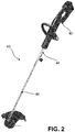
- the lawn maintenance tool 40 includes a power head 42, an adapter 44 attached to the power head, and a working attachment 46 connected to the adapter 44.
- the working attachment 46 is attachable directly to the power head 42.
- the working attachment 46 shown in FIG. 2 is a string trimmer, but it should be understood by one having ordinary skill in the art that the working attachment 46 may also be a blower, hedge trimmer, edger, tiller, chainsaw or polesaw, blower, or the like.
- the adapter 44 allows the working attachment 46 to provide the handheld tool 40 with at least three different lengths as well as allow both battery-powered and engine-powered working attachments 46 to be attached to the power head 42, as will be explained below.
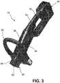
- the power head 42 includes a power source 48, a first handle 50, a control mechanism 52, a second handle 54, a power generator 56 located within a housing 58, and a first attachment mechanism 60, as shown in FIG. 3 .
- the power source 48 is illustrated as a battery, but it should be understood by one having ordinary skill in the art that the power source can alternatively be a connecting mechanism for creating an electrical connection via power outlet, a hybrid-electric power source, or any other compact source that can generate an electrical output.
- the illustrated battery can be a rechargeable or a replaceable battery.
- the power source 48 is removably attachable to the housing 58.
- the power source 48 is located at the rear of the power head 42. Because the various embodiments of the power source 48 have significant weight with respect to the remaining members of the lawn maintenance tools 10, positioning the power source 48 at the rear of the power head 42 provides a more evenly distributed weight when the working attachment 46 is attached to the forward end of the power head 42.
- the first handle 50 is positioned adjacent to the rear of the power head 42, adjacent to the power source 48, as shown in FIG. 3 .
- the first handle 50 is a member that is graspable by an operator which allows the operator to lift and carry the lawn maintenance tool 10 as well as control the movement of the working attachment 46 ( FIG. 2 ) attached to the power head 42.
- the first handle 50 forms part of the housing 58.
- the first handle 50 is formed separately from the housing 58 and is subsequently attached thereto during assembly.
- the first handle 50 is formed as an elongated, somewhat cylindrical member that is oriented generally along the longitudinal axis of the power head 42.
- the first handle 50 can be any member positioned near the rear end of the power head 42 and is graspable by an operator.
- the trigger 52 is positioned immediately adjacent to the first handle 54 to allow an operator to simply and easily control the speed of the power generator 56, as shown in FIG. 3 .
- the trigger 52 is a movable lever, typically operated by an operator's index finger or finger positioned closest to the trigger 52.
- the trigger 52 is operatively connected to the power generator 56, and is configured to increase the power output to from the power generator 56 when the trigger 52 is pulled and to decrease the power output from the power generator 56 when the trigger 52 is released.
- the trigger 52 is infinitely adjustable between a full-stop position and a full-power position.
- the power generator 56 positioned within the housing 58 is located longitudinally forward relative to the first handle 50 and the trigger 52, as shown in FIG. 3 .
- the power generator 56 is an electrically-powered motor which generates an output source of power that is transferrable to the working attachment 46.
- the output source of power from the power generator 56 may be a reciprocating movement for a working attachment 46 such as hedge trimmers.
- the output source of power from the power generator 56 may alternatively or additionally be rotational movement for working attachments 46 such as string trimmers, blowers, edgers, tillers, blowers, or chainsaws/polesaws. It should be understood by one having ordinary skill in the art that the type of output from the power generator 56 may be any type(s) sufficient to adequately power any working attachment 46 for the handheld lawn maintenance tool 40.
- the second handle 54 is positioned longitudinally forward of the power generator 56, and extends from the housing 58 to allow an operator to simultaneously grasp both the first and second handles 50, 54.
- the second handle 54 shown in FIG. 3 is a generally D-shaped handle, wherein the angle of the second handle 54 relative to the housing 58 is adjustable in the fore/aft direction for a more ergonomic fit for the operator.
- the second handle 54 is an elongated bar having a padded cover that extends laterally from the housing 58. This second handle 54 that extends laterally is often utilized on string trimmers.
- the second handle 54 is removable or otherwise inter-changeable to allow an operator a choice as to the particular design of the second handle 54 based upon preference or upon the type of working attachment 46 attached to the power head 42.
- the power head 42 is configured to include a second handle 54, thereby providing a more consistent user experience for each of the working attachments 46 attachable
- the forward distal end of the power head 42 is formed as a first attachment mechanism 60 to which the adapter 44 or a working attachment 46 is secured to positively connect the working attachment 46 to the power head 42, as shown in FIGS. 2-3 .
- the first attachment mechanism 60 includes a recess 62 into which the adapter 44 or working attachment 46 is received.
- a power transfer mechanism (not shown) is located within the recess 62, wherein the power transfer mechanism is configured to transfer power from the power generator 56 to the working attachment 46 in order to drive the tool of the working attachment.
- the first attachment mechanism 60 also includes a spring-biased release button 64 that has an indexing pin (not shown) that extends into the recess 62 and is biased into engagement with the adapter 44 or working attachment 46 when one of those is positioned within the recess 62 of the first attachment mechanism 60.
- the indexing pin (not shown) of the release button 64 is pushed outwardly away from the recess 62 until the indexing pin aligns with an indexing aperture (not shown) of the adapter 44 or working attachment 46. Once the indexing pin and indexing aperture are aligned, the indexing pin is biased into the indexing aperture, thereby positively connecting the power head 42 to the working attachment 46.
- the release button 64 is pushed by the operator, and such actuation causes the indexing pin to be withdrawn from the indexing aperture. With the indexing pin withdrawn from the adapter 44 or working attachment 46, these can then be withdrawn.
- the illustrated first attachment mechanism 60 is provided as an exemplary embodiment, but it should be understood by one having ordinary skill in the art that any other mechanical mechanism(s) can be used for the first attachment mechanism 60 to provide a positive connection between the power head 42 and the adapter 44 or working attachment 46.
- FIG. 4 shows an exemplary embodiment of an adapter 44 that is one end that is attachable to the power head 42 and an opposing end that is configured to be attachable to a working attachment 46.
- the adapter 44 includes a second attachment mechanism 66, an extension member 68, and a first connector 70.
- the second attachment mechanism 66 is formed as a cap that is either insertable into the recess 62 of the first attachment mechanism 60 or is positionable about the first attachment mechanism.
- the second attachment mechanism 66 is configured to allow the adapter 44 to be releasably attachable to the power head 42. It should be understood by one having ordinary skill in the art that the second attachment mechanism 66 can be formed as any structure sufficient to correspond to the first attachment mechanism 60 to allow for a releasable attachment between the first and second attachment mechanisms 60, 66.
- the adapter 44 further includes an extension member 68 that extends between the first attachment mechanism 60 and the first connector 70, as shown in FIG. 4 .
- the extension member 68 is a generally tubular member that is hollow but may include a mechanism for transferring rotation from the power generator 56 to the tool of the working attachment 46.
- the length of the extension member 68 should be long enough to provide at least a nominal extension of length between the working attachment 46 and the power head 42.
- the extension member 68 is adapted to provide either an extension of length for the handheld lawn maintenance tool 10 and/or a conduit for conducting power from the power head 42 to the working attachment 46.
- the adapter 44 further includes a first connector 70 that is configured to provide an attachment to working attachments 46 that are either battery-powered or gasoline-powered.
- the first connector 70 includes a spring-biased indexing pin (not shown) similar to the spring-biased indexing pin of the first attachment mechanism 60.
- the first connector 70 further includes a rotatable handle 72 having a threaded engagement such that rotation of the handle 72 causes the end of the threaded engagement to contact and abut the working attachment 46 to provide a secure or secondary connection between the working attachment 46 and the adapter 44.
- FIG. 5 illustrates a power head 42 attached to an adapter 44, wherein a working attachment 46 is attached to the adapter 44.
- the illustrated working attachments 46 are a string trimmer, an axial blower, and a hedge trimmer. Each of the working attachments 46 is attachable to the adapter 44 or directly to the power head 42.
- Each working attachment 46 includes a tool 74 having a second connector 76 extending therefrom.
- the working attachment 46 formed as a string trimmer is attached to a separate boom 78 that extends between the second connector 76 and the tool 74.
- the boom 78 is an elongated member that is generally hollow tubular member that allows the tool 74 to be positioned a distance away from the power head 42.
- the working attachment 46 formed as an axial blower includes a second connector 76 that allows the axial blower to be releasably attachable to both the adapter 44, the power head 42, as shown in FIGS. 6A-6B .
- FIG. 7A In another embodiment in which the illustrated working attachment 46 is formed as a hedge trimmer being attachable directly to the power head 42, as shown in FIG. 7A .
- the hedge trimmer working attachment 46 is also attachable to an adapter 44 that is attached to the power head 42, as shown in FIG. 7B .
- the hedge trimmer working attachment 46 is further attachable to a boom 78 that is attachable to the adapter 44 that is connected to the power head 42, as shown in FIG. 7C.
- FIGS. 7A-7C illustrate the manner in which working attachments 46 are attachable directly and/or indirectly to the power head 42.
- the power head 42 having integrated first and second handles 50, 54 as well as having the power generator 56 also integrated into the power head 42 reduces the stress and required effort for an operator, even when the working attachment 46 is positioned in a cantilevered, extended position as shown in FIG. 7C .
- FIG. 8 illustrates alternative working attachment 46 embodiments, including (from left to right) a string trimmer, an edger, a tiller, a chainsaw or polesaw, a blower, and a hedge trimmer.
- Each of the working attachments 46 shown in FIG. 8 are powered by a gasoline engine located within the power head, but the adapter 44 of the present invention allows these working attachments 46 to be attachable to a power head 42 in which the power generator 46 is a battery or otherwise non-gasoline-powered.
- the power head 42 includes a power source 48 that is formed as a combined power source and power generator, wherein the combined mechanism is an internal combustion engine powered by gasoline, propane, diesel, compressed natural gas, hydrogen gas, biofuel, or the like, as shown in FIG. 9 .
- This power source/power generator is positioned at the rear end of the power head 42 in order to aid in balancing the weight of the working attachment 46 that extends from the forward end of the power head 42.
- the power head 42 includes an integrated first and second handles 50, 54 as well as a first attachment mechanism 60, which is configured to be releasably attachable to the working attachment 46.
Landscapes
- Life Sciences & Earth Sciences (AREA)
- Environmental Sciences (AREA)
- Engineering & Computer Science (AREA)
- Biodiversity & Conservation Biology (AREA)
- Ecology (AREA)
- Forests & Forestry (AREA)
- Mechanical Engineering (AREA)
- Soil Sciences (AREA)
- Architecture (AREA)
- Civil Engineering (AREA)
- Structural Engineering (AREA)
- Harvester Elements (AREA)
- Portable Power Tools In General (AREA)
Description
- The present invention is directed to a handheld lawn maintenance tool.
- Handheld lawn maintenance tools, and more particularly, interchangeable handheld lawn maintenance tools, have become increasingly popular among homeowners. They allow homeowners to purchase a single power head that can be used to power multiple different attachments, wherein each attachment is configured to perform a different function or perform a different operation of lawn maintenance. Most power heads are fairly basic, and the attachment mechanism is typically configured to only allow similarly-branded attachments to be connected thereto.
- For example, the handheld
lawn maintenance tool 10a, shown as a string trimmer inFIG. 1A , includes apower head 12a that is configured to receive abattery 14a that is configured to provide electrical power. Thepower head 12a includes afirst handle 16a that allows an operator to grasp thepower head 12a during operation. Thefirst handle 16a also includes atrigger 18a that adjusts the speed of theworking attachment 20a. The workingattachment 20a includes aboom 22a, asecond handle 24a attached to theboom 22a, amotor 26a, and atool 28a driven by themotor 26a. Thebattery 14a provides electrical power to themotor 26a to drive thetool 28a, wherein the electrical connection extends through theboom 22a. Other workingattachments 20a can also be attached to thepower head 12a, and with each of the other attachments, thebatter 14a provides electrical power to a motor or other driver located on the workingattachment 20a. Often, the motor on the workingattachment 20a is typically positioned at the opposite end of the handheldlawn maintenance tool 10a relative to thebattery 14a in a substantially cantilevered manner. - Another example of a handheld
lawn maintenance tool 10b, shown as a string trimmer inFIG. 1B , includes apower head 12b that is configured to receive abattery 14b that is configured to provide electrical power. Thepower head 12b includes afirst handle 16b that allows an operator to grasp thepower head 12b during operation. Thefirst handle 16b also includes atrigger 18a that adjusts the speed of the workingattachment 20b. The workingattachment 20b includes aboom 22b, asecond handle 24b attached to theboom 22b, amotor 26b, and atool 28b driven by themotor 26b. In a similar manner to the handheldlawn maintenance tool 10a shown inFIG. 1A , thebattery 14b of this handheldlawn maintenance tool 10b provides electrical power to themotor 26b to drive thetool 28b, wherein the electrical connection extends through theboom 22b. - The weight of the
motor boom tool lawn maintenance tools boom first handle tool lawn maintenance tool - Additionally, these battery-powered
power heads lawn maintenance tools - Examples of handheld lawn maintenance tools are provided in the following patent documents:
US2014/262388A1 ,EP2580954A1 andEP2407021A1 . - The present invention provides a handheld lawn maintenance tool according to appended claim 1. Preferred aspects of the invention are defined in the dependent claims.
- Advantages of the present invention will become more apparent to those skilled in the art from the following description of the embodiments of the invention which have been shown and described by way of illustration. As will be realized, the invention is capable of other and different embodiments, and its details are capable of modification in various respects.
- These and other features of the present invention, and their advantages, are illustrated specifically in embodiments of the invention now to be described, by way of example, with reference to the accompanying diagrammatic drawings, in which:
-
FIG. 1A is a prior art string trimmer; -
FIG. 1B is another prior art string trimmer; -
FIG. 2 is an embodiment of a handheld lawn maintenance tool; -
FIG. 3 is an embodiment of a power head; -
FIG. 4 is an embodiment of an adapter; -
FIG. 5 shows a schematic of multiple working attachments being releasably attachable to a power head at a plurality of positions; -
FIG. 6A is a working attachment attachable directly to a power head; -
FIG. 6B is the working attachment shown inFIG. 6A attachable to an adapter that is attached to the power head; -
FIG. 7A is a working attachment attachable directly to a power head; -
FIG. 7B is the working attachment shown inFIG. 7A attachable to an adapter that is attached to the power head; -
FIG. 7C is the working attachment shown inFIG. 7A attachable to a boom that is attached to an adapter that is attached to the power head; -
FIG. 8 is a schematic of multiple gasoline-powered working attachments being attachable to an adapter attached to a power head; and -
FIG. 9 is another embodiment of a power head having a combined power source/power generator as well as integrated first and second handles. - It should be noted that all the drawings are diagrammatic and not drawn to scale. Relative dimensions and proportions of parts of these figures have been shown exaggerated or reduced in size for the sake of clarity and convenience in the drawings. The same reference numbers are generally used to refer to corresponding or similar features in the different embodiments. Accordingly, the drawing(s) and description are to be regarded as illustrative in nature and not as restrictive.
- Referring to
FIG. 2 , an exemplary embodiment of a handheldlawn maintenance tool 40 is shown. In the illustrated embodiment, thelawn maintenance tool 40 includes apower head 42, anadapter 44 attached to the power head, and a workingattachment 46 connected to theadapter 44. In other embodiments, theworking attachment 46 is attachable directly to thepower head 42. The workingattachment 46 shown inFIG. 2 is a string trimmer, but it should be understood by one having ordinary skill in the art that the workingattachment 46 may also be a blower, hedge trimmer, edger, tiller, chainsaw or polesaw, blower, or the like. Theadapter 44 allows the workingattachment 46 to provide thehandheld tool 40 with at least three different lengths as well as allow both battery-powered and engine-powered workingattachments 46 to be attached to thepower head 42, as will be explained below. - In an embodiment, the
power head 42 includes apower source 48, afirst handle 50, acontrol mechanism 52, asecond handle 54, apower generator 56 located within ahousing 58, and afirst attachment mechanism 60, as shown inFIG. 3 . Thepower source 48 is illustrated as a battery, but it should be understood by one having ordinary skill in the art that the power source can alternatively be a connecting mechanism for creating an electrical connection via power outlet, a hybrid-electric power source, or any other compact source that can generate an electrical output. The illustrated battery can be a rechargeable or a replaceable battery. Thepower source 48 is removably attachable to thehousing 58. Thepower source 48 is located at the rear of thepower head 42. Because the various embodiments of thepower source 48 have significant weight with respect to the remaining members of thelawn maintenance tools 10, positioning thepower source 48 at the rear of thepower head 42 provides a more evenly distributed weight when the workingattachment 46 is attached to the forward end of thepower head 42. - The
first handle 50 is positioned adjacent to the rear of thepower head 42, adjacent to thepower source 48, as shown inFIG. 3 . Thefirst handle 50 is a member that is graspable by an operator which allows the operator to lift and carry thelawn maintenance tool 10 as well as control the movement of the working attachment 46 (FIG. 2 ) attached to thepower head 42. In an embodiment, thefirst handle 50 forms part of thehousing 58. In other embodiments, thefirst handle 50 is formed separately from thehousing 58 and is subsequently attached thereto during assembly. Thefirst handle 50 is formed as an elongated, somewhat cylindrical member that is oriented generally along the longitudinal axis of thepower head 42. In other embodiments, thefirst handle 50 can be any member positioned near the rear end of thepower head 42 and is graspable by an operator. - The
trigger 52, or other similar speed control mechanism, is positioned immediately adjacent to thefirst handle 54 to allow an operator to simply and easily control the speed of thepower generator 56, as shown inFIG. 3 . Thetrigger 52 is a movable lever, typically operated by an operator's index finger or finger positioned closest to thetrigger 52. Thetrigger 52 is operatively connected to thepower generator 56, and is configured to increase the power output to from thepower generator 56 when thetrigger 52 is pulled and to decrease the power output from thepower generator 56 when thetrigger 52 is released. Thetrigger 52 is infinitely adjustable between a full-stop position and a full-power position. - The
power generator 56 positioned within thehousing 58 is located longitudinally forward relative to thefirst handle 50 and thetrigger 52, as shown inFIG. 3 . In the illustrated embodiment, thepower generator 56 is an electrically-powered motor which generates an output source of power that is transferrable to the workingattachment 46. The output source of power from thepower generator 56 may be a reciprocating movement for a workingattachment 46 such as hedge trimmers. The output source of power from thepower generator 56 may alternatively or additionally be rotational movement for workingattachments 46 such as string trimmers, blowers, edgers, tillers, blowers, or chainsaws/polesaws. It should be understood by one having ordinary skill in the art that the type of output from thepower generator 56 may be any type(s) sufficient to adequately power any workingattachment 46 for the handheldlawn maintenance tool 40. - The
second handle 54 is positioned longitudinally forward of thepower generator 56, and extends from thehousing 58 to allow an operator to simultaneously grasp both the first andsecond handles second handle 54 shown inFIG. 3 is a generally D-shaped handle, wherein the angle of thesecond handle 54 relative to thehousing 58 is adjustable in the fore/aft direction for a more ergonomic fit for the operator. In another embodiment (not shown), thesecond handle 54 is an elongated bar having a padded cover that extends laterally from thehousing 58. Thissecond handle 54 that extends laterally is often utilized on string trimmers. In an embodiment, thesecond handle 54 is removable or otherwise inter-changeable to allow an operator a choice as to the particular design of thesecond handle 54 based upon preference or upon the type of workingattachment 46 attached to thepower head 42. Thepower head 42 is configured to include asecond handle 54, thereby providing a more consistent user experience for each of the workingattachments 46 attachable - The forward distal end of the
power head 42 is formed as afirst attachment mechanism 60 to which theadapter 44 or a workingattachment 46 is secured to positively connect the workingattachment 46 to thepower head 42, as shown inFIGS. 2-3 . In an embodiment, thefirst attachment mechanism 60 includes arecess 62 into which theadapter 44 or workingattachment 46 is received. A power transfer mechanism (not shown) is located within therecess 62, wherein the power transfer mechanism is configured to transfer power from thepower generator 56 to the workingattachment 46 in order to drive the tool of the working attachment. Thefirst attachment mechanism 60 also includes a spring-biasedrelease button 64 that has an indexing pin (not shown) that extends into therecess 62 and is biased into engagement with theadapter 44 or workingattachment 46 when one of those is positioned within therecess 62 of thefirst attachment mechanism 60. When theadapter 44 or workingattachment 46 is inserted into therecess 62 of thefirst attachment mechanism 60, the indexing pin (not shown) of therelease button 64 is pushed outwardly away from therecess 62 until the indexing pin aligns with an indexing aperture (not shown) of theadapter 44 or workingattachment 46. Once the indexing pin and indexing aperture are aligned, the indexing pin is biased into the indexing aperture, thereby positively connecting thepower head 42 to the workingattachment 46. To release the connection to allow theadapter 44 or workingattachment 46 from thepower head 42, therelease button 64 is pushed by the operator, and such actuation causes the indexing pin to be withdrawn from the indexing aperture. With the indexing pin withdrawn from theadapter 44 or workingattachment 46, these can then be withdrawn. The illustratedfirst attachment mechanism 60 is provided as an exemplary embodiment, but it should be understood by one having ordinary skill in the art that any other mechanical mechanism(s) can be used for thefirst attachment mechanism 60 to provide a positive connection between thepower head 42 and theadapter 44 or workingattachment 46. -
FIG. 4 shows an exemplary embodiment of anadapter 44 that is one end that is attachable to thepower head 42 and an opposing end that is configured to be attachable to a workingattachment 46. Theadapter 44 includes asecond attachment mechanism 66, anextension member 68, and afirst connector 70. Thesecond attachment mechanism 66 is formed as a cap that is either insertable into therecess 62 of thefirst attachment mechanism 60 or is positionable about the first attachment mechanism. Thesecond attachment mechanism 66 is configured to allow theadapter 44 to be releasably attachable to thepower head 42. It should be understood by one having ordinary skill in the art that thesecond attachment mechanism 66 can be formed as any structure sufficient to correspond to thefirst attachment mechanism 60 to allow for a releasable attachment between the first andsecond attachment mechanisms - In the illustrated embodiment, the
adapter 44 further includes anextension member 68 that extends between thefirst attachment mechanism 60 and thefirst connector 70, as shown inFIG. 4 . Theextension member 68 is a generally tubular member that is hollow but may include a mechanism for transferring rotation from thepower generator 56 to the tool of the workingattachment 46. The length of theextension member 68 should be long enough to provide at least a nominal extension of length between the workingattachment 46 and thepower head 42. In an embodiment, theextension member 68 is adapted to provide either an extension of length for the handheldlawn maintenance tool 10 and/or a conduit for conducting power from thepower head 42 to the workingattachment 46. - The
adapter 44 further includes afirst connector 70 that is configured to provide an attachment to workingattachments 46 that are either battery-powered or gasoline-powered. Thefirst connector 70 includes a spring-biased indexing pin (not shown) similar to the spring-biased indexing pin of thefirst attachment mechanism 60. Thefirst connector 70 further includes arotatable handle 72 having a threaded engagement such that rotation of thehandle 72 causes the end of the threaded engagement to contact and abut the workingattachment 46 to provide a secure or secondary connection between the workingattachment 46 and theadapter 44. -
FIG. 5 illustrates apower head 42 attached to anadapter 44, wherein a workingattachment 46 is attached to theadapter 44. The illustrated workingattachments 46 are a string trimmer, an axial blower, and a hedge trimmer. Each of the workingattachments 46 is attachable to theadapter 44 or directly to thepower head 42. Each workingattachment 46 includes atool 74 having asecond connector 76 extending therefrom. The workingattachment 46 formed as a string trimmer is attached to aseparate boom 78 that extends between thesecond connector 76 and thetool 74. Theboom 78 is an elongated member that is generally hollow tubular member that allows thetool 74 to be positioned a distance away from thepower head 42. The workingattachment 46 formed as an axial blower includes asecond connector 76 that allows the axial blower to be releasably attachable to both theadapter 44, thepower head 42, as shown inFIGS. 6A-6B . - In another embodiment in which the illustrated working
attachment 46 is formed as a hedge trimmer being attachable directly to thepower head 42, as shown inFIG. 7A . The hedgetrimmer working attachment 46 is also attachable to anadapter 44 that is attached to thepower head 42, as shown inFIG. 7B . The hedgetrimmer working attachment 46 is further attachable to aboom 78 that is attachable to theadapter 44 that is connected to thepower head 42, as shown inFIG. 7C. FIGS. 7A-7C illustrate the manner in which workingattachments 46 are attachable directly and/or indirectly to thepower head 42. Thepower head 42 having integrated first andsecond handles power generator 56 also integrated into thepower head 42 reduces the stress and required effort for an operator, even when the workingattachment 46 is positioned in a cantilevered, extended position as shown inFIG. 7C . -
FIG. 8 illustrates alternative workingattachment 46 embodiments, including (from left to right) a string trimmer, an edger, a tiller, a chainsaw or polesaw, a blower, and a hedge trimmer. Each of the workingattachments 46 shown inFIG. 8 are powered by a gasoline engine located within the power head, but theadapter 44 of the present invention allows these workingattachments 46 to be attachable to apower head 42 in which thepower generator 46 is a battery or otherwise non-gasoline-powered. - In another embodiment, the
power head 42 includes apower source 48 that is formed as a combined power source and power generator, wherein the combined mechanism is an internal combustion engine powered by gasoline, propane, diesel, compressed natural gas, hydrogen gas, biofuel, or the like, as shown inFIG. 9 . This power source/power generator is positioned at the rear end of thepower head 42 in order to aid in balancing the weight of the workingattachment 46 that extends from the forward end of thepower head 42. Thepower head 42 includes an integrated first andsecond handles first attachment mechanism 60, which is configured to be releasably attachable to the workingattachment 46.
Claims (15)
- A handheld lawn maintenance tool (10) comprising a power head (42) extending along a longitudinal axis between a front and a rear, wherein the power head (42) includes:- a power source (48), located at the rear of the power head (42);- a housing (58);- a first handle (50), operatively connected to the housing (58), a power generator (56) positioned within said housing (58) and operatively connected to the power source (48);- a second handle (54), operatively connected to said housing (58);- a control mechanism (52) positioned adjacent to said first handle (50), and- a first attachment mechanism (60) extending from said housing for receiving a releasably attachable working attachment (46),
the handheld lawn maintenance tool (10) being characterized in thatthe first handle (50) is elongated along the longitudinal axis of the power head (42), and is positioned adjacent to the rear of the power head (42), adjacent to the power source (48),the second handle (54), extends from said housing (58) and is positioned longitudinally forward of the power generator (56), at the front of the power head (42). - The handheld lawn maintenance tool (10) of Claim 1, wherein said power source (48) is removably attachable to said housing (58).
- The handheld lawn maintenance tool (10) of Claim 2, wherein said power source (48) is a rechargeable battery.
- The handheld lawn maintenance tool (10) of Claim 1, wherein said power source (48) is an internal combustion engine.
- The handheld lawn maintenance tool (10) of Claim 1, comprising an adapter (44), wherein said first attachment mechanism (60) is releasably attachable to said adapter (44).
- The handheld lawn maintenance tool (10) of Claim 5, wherein said adapter (44) is attachable to both battery-powered working attachment (46) and gasoline-powered working attachment (46).
- The handheld maintenance tool (10) of any of the previous claims, wherein said power source (48) is a connecting mechanism for creating an electrical connection via power outlet.
- The handheld maintenance tool (10) of any of the previous claims, wherein said power generator (56) is configured for generating a reciprocating movement as an output source of power.
- The handheld maintenance tool (10) of claim any of the previous claims from 1 to 9, wherein said power generator (56) is configured for generating a rotational movement as an output source of power.
- The handheld maintenance tool of any of the previous claims, wherein the first attachment mechanism (60) includes a recess (62) for receiving a releasably attachable working attachment (46) or an adapter (44).
- The handheld maintenance tool (10) of claim 10, comprising a power transfer mechanism located within the recess (62), wherein the power transfer mechanism provides a connection between the power head (42) and the adapter (44) or the working attachment (46), and is configured to transfer power from the power generator (56) to the working attachment (46) in order to drive the tool of the working attachment (46).
- The handheld maintenance tool (10) of any of the previous claims, further comprising a trigger (52) configured to increase the power generated by the power generator (56) when the trigger (52) is pulled and to decrease the power generated by the power generator (56) when the trigger (52) is released.
- The handheld maintenance tool (10) of any of the previous claims, comprising a working attachment (46) directly attached to the power head (42).
- The handheld maintenance tool (10) of any of the previous claims from 1 to 12, comprising an adapter (44) attached to the power head (42) and a working attachment (46) connected to the adapter (44).
- The handheld maintenance tool (10) of claim 13 or 14, comprising a boom (78) attachable to the adapter (44) that is connected to the power head (42).
Applications Claiming Priority (2)
| Application Number | Priority Date | Filing Date | Title |
|---|---|---|---|
| US201562112962P | 2015-02-06 | 2015-02-06 | |
| PCT/US2016/015662 WO2016126547A1 (en) | 2015-02-06 | 2016-01-29 | Handheld lawn maintenance tool |
Publications (2)
| Publication Number | Publication Date |
|---|---|
| EP3253192A1 EP3253192A1 (en) | 2017-12-13 |
| EP3253192B1 true EP3253192B1 (en) | 2021-03-10 |
Family
ID=55398440
Family Applications (1)
| Application Number | Title | Priority Date | Filing Date |
|---|---|---|---|
| EP16705379.2A Active EP3253192B1 (en) | 2015-02-06 | 2016-01-29 | Handheld lawn maintenance tool |
Country Status (6)
| Country | Link |
|---|---|
| US (2) | US12120969B2 (en) |
| EP (1) | EP3253192B1 (en) |
| CN (2) | CN107205338A (en) |
| AU (1) | AU2016215638B2 (en) |
| CA (2) | CA3059599A1 (en) |
| WO (1) | WO2016126547A1 (en) |
Families Citing this family (44)
| Publication number | Priority date | Publication date | Assignee | Title |
|---|---|---|---|---|
| AU2017336937A1 (en) * | 2016-09-29 | 2019-03-28 | Mtd Products Inc | Split power tool |
| US10537983B2 (en) * | 2016-10-17 | 2020-01-21 | Black & Decker, Inc. | Modular power tool |
| EP3955454A1 (en) * | 2016-11-11 | 2022-02-16 | Black & Decker Inc. | Configurable motor system |
| US10470367B2 (en) * | 2017-02-23 | 2019-11-12 | Rex A. Eiserer | Cutting web |
| US20180317396A1 (en) * | 2017-05-05 | 2018-11-08 | Briggs & Stratton Corporation | Battery powered handheld outdoor power equipment |
| US10688647B2 (en) * | 2017-05-19 | 2020-06-23 | The Toro Company | Lawn and garden tool with boom having adjustable length and detachable boom sections |
| CN207559587U (en) * | 2017-06-15 | 2018-06-29 | 浙江白马实业有限公司 | A kind of backward compatible controller of the voltage of garden instrument |
| CN107432155A (en) * | 2017-10-11 | 2017-12-05 | 宁波鄞州晶浩正机械设备有限公司 | A kind of weeder |
| EP3694303B1 (en) * | 2017-10-13 | 2024-05-29 | MTD Products Inc | Handheld tool for single-handed operation |
| WO2019109277A1 (en) * | 2017-12-06 | 2019-06-13 | Husqvarna Ab | Mating interface for a power head configured to operate multiple tool attachments |
| USD871184S1 (en) | 2017-12-06 | 2019-12-31 | Husqvarna Ab | Power head with tool attachment interface |
| CN109924022A (en) * | 2017-12-15 | 2019-06-25 | 南京德朔实业有限公司 | A kind of grass-mowing machine |
| US10655299B2 (en) * | 2018-02-06 | 2020-05-19 | Echo Incorporated | Handheld trenching apparatus and method of using the same |
| EP3536461B1 (en) * | 2018-03-08 | 2020-11-25 | Andreas Stihl AG & Co. KG | Method for type-dependent operation of an electrical drive unit and system |
| US11485003B2 (en) * | 2018-05-23 | 2022-11-01 | Milwaukee Electric Tool Corporation | Powerhead unit for tool |
| US11343973B2 (en) | 2018-05-23 | 2022-05-31 | Milwaukee Electric Tool Corporation | Pole saw |
| EP3599311B1 (en) | 2018-07-25 | 2026-03-11 | Techtronic Outdoor Products Technology Limited | Outdoor surface treating apparatus and associated accessory tool assembly |
| WO2020041419A1 (en) * | 2018-08-22 | 2020-02-27 | Magnetic Focus, LLC | Ergonomic apparatus for handheld tools and powered tools |
| CN108934212A (en) * | 2018-08-31 | 2018-12-07 | 合肥桴槎山软籽石榴研发有限公司 | A kind of agricultural planting machine soil crushing device |
| EP3876694A4 (en) * | 2018-11-09 | 2022-11-09 | Techtronic Cordless GP | Modular power unit and tool using a modular power unit |
| JP7281917B2 (en) * | 2019-02-18 | 2023-05-26 | 株式会社マキタ | electric work machine |
| JP7224950B2 (en) | 2019-02-18 | 2023-02-20 | 株式会社マキタ | electric work machine |
| TWI691262B (en) * | 2019-10-08 | 2020-04-21 | 何炳梓 | Electric gardening machine |
| WO2021098438A1 (en) * | 2019-11-18 | 2021-05-27 | 苏州宝时得电动工具有限公司 | Garden blower |
| WO2021120859A1 (en) | 2019-12-19 | 2021-06-24 | Techtronic Cordless Gp | Electric cultivator |
| US11806856B1 (en) * | 2020-01-15 | 2023-11-07 | Mira Smart Investment, Llc | Motorized multi-function tool |
| WO2021257954A1 (en) | 2020-06-19 | 2021-12-23 | Milwaukee Electric Tool Corporation | String trimmer |
| CN114073201A (en) * | 2020-08-14 | 2022-02-22 | 南京德朔实业有限公司 | Long-rod chain saw |
| US12035661B2 (en) * | 2020-10-27 | 2024-07-16 | Clifford Peters | Multi-task blower platform, device and system |
| US12515307B2 (en) * | 2020-12-04 | 2026-01-06 | Globe (jiangsu) Co., Ltd. | Power tool system |
| US11707019B2 (en) | 2021-02-24 | 2023-07-25 | Towa Industries, Incorporated | Method of refurbishing a landscape power tool |
| US11697199B2 (en) * | 2021-02-24 | 2023-07-11 | Towa Industries, Incorporated | Power landscaping tool ensemble for using multiple tool heads |
| CN115217056A (en) * | 2021-04-19 | 2022-10-21 | 南京泉峰科技有限公司 | hair dryer |
| USD1029594S1 (en) * | 2021-04-23 | 2024-06-04 | Zhejiang Safun Industrial Co., Ltd. | Grass trimmer |
| US11787033B2 (en) * | 2021-05-04 | 2023-10-17 | Nick Semitka | Multifunctional reciprocating utility device |
| CN216399524U (en) * | 2021-08-20 | 2022-04-29 | 米沃奇电动工具公司 | Interchangeable tool attachment and system |
| DE102021132352A1 (en) * | 2021-12-08 | 2023-06-15 | Mtd Products Inc. | Processing device, in particular gardening and/or household device, handling device and connection section for such a device and use of such a connection section |
| DE102021132353A1 (en) * | 2021-12-08 | 2023-06-15 | Mtd Products Inc. | Handling device and processing device, in particular gardening and/or household appliance, with such a handling device |
| CN116352659A (en) | 2021-12-28 | 2023-06-30 | 创科无线普通合伙 | Work tools and their transmission systems |
| US20230226714A1 (en) * | 2022-01-14 | 2023-07-20 | Milwaukee Electric Tool Corporation | Saw systems having interchangeable saw cartridges |
| US20240397878A1 (en) * | 2023-06-04 | 2024-12-05 | Greenworks (Jiangsu) Co., Ltd. | Hedge Trimmer |
| IT202300012309A1 (en) * | 2023-06-15 | 2024-12-15 | Stiga S P A In Breve Anche St S P A | DEVICE FOR CARRYING OUT MAINTENANCE OPERATIONS ON A GROUND OR GARDEN |
| US12589477B2 (en) * | 2023-11-30 | 2026-03-31 | Stanley Black & Decker Inc. | Multi-headed power tool and fastening system for same and systems for fastening heads thereon |
| US12594657B2 (en) * | 2023-11-30 | 2026-04-07 | Stanley Black & Decker, Inc. | Multi-headed power tool and systems for fastening heads thereon |
Family Cites Families (36)
| Publication number | Priority date | Publication date | Assignee | Title |
|---|---|---|---|---|
| US3129771A (en) * | 1961-08-02 | 1964-04-21 | Clifford G Lidstone | Cultivating tool |
| USD250450S (en) * | 1978-05-25 | 1978-12-05 | The Toro Company | Cordless vegetation trimmer |
| US4286675A (en) | 1979-06-25 | 1981-09-01 | Beaird-Poulan Division Of Emerson Electric Co. | Narrow profile power handle for line trimmer and the like |
| US4588335A (en) * | 1984-09-14 | 1986-05-13 | Pearson Jr Claude C | Quick change tool retention device for power operated mechanism |
| US5181369A (en) | 1991-03-01 | 1993-01-26 | Inertia Dynamics Corporation | Battery powered line trimmer |
| US5184369A (en) | 1991-11-14 | 1993-02-09 | Mcelroy Lucian G | Non-contacting automotive dryer control circuit |
| US5345684A (en) * | 1993-01-25 | 1994-09-13 | Wci Outdoor Products, Inc. | Flexible line trimmer having an anti-vibration handle |
| US5265341A (en) * | 1993-01-29 | 1993-11-30 | Pyobi Outdoor Products, Inc. | Battery powered line trimmer arm rest |
| AU3546395A (en) * | 1994-09-09 | 1996-03-27 | Ryobi North America, Inc. | Attachment system for battery powered tool |
| US5815928A (en) * | 1995-07-28 | 1998-10-06 | Wci Outdoor Products, Inc. | Portable powered lawn and garden tool |
| US5810093A (en) * | 1996-10-03 | 1998-09-22 | Media Group | Multi-purpose landscaping device for use with a hand-held rotary power tool |
| US5862595A (en) * | 1996-11-07 | 1999-01-26 | Keane; Stephen Timothy | Combined trimmer and vacuum apparatus |
| US5987756A (en) | 1997-07-23 | 1999-11-23 | Mcculloch Corporation | Head and head assembly for a string trimmer |
| US6006434A (en) | 1997-09-30 | 1999-12-28 | Hoffco, Inc. | Quick-release component connector for lawn tool |
| US6769494B2 (en) | 2001-04-30 | 2004-08-03 | Powerqwest, Inc. | Combination line trimmer and edger |
| US6973728B2 (en) * | 2002-04-04 | 2005-12-13 | The Toro Company | Filament trimmer with dual triggers |
| US6955227B1 (en) * | 2002-09-21 | 2005-10-18 | Versatile Housewares | Auger for mixing and burrowing |
| USD510512S1 (en) | 2004-03-24 | 2005-10-11 | Black & Decker Inc. | String trimmer |
| US7484300B2 (en) | 2004-09-09 | 2009-02-03 | Black & Decker Inc. | Extensible pole saw having separable sections |
| CA2524426C (en) * | 2004-10-27 | 2013-01-15 | Andreas Stihl Ag & Co. Kg | Protective shield for a trimmer |
| GB0503857D0 (en) * | 2005-02-25 | 2005-04-06 | Gmca Pty Ltd | Cutting tool |
| GB0509745D0 (en) * | 2005-05-13 | 2005-06-22 | Black & Decker Inc | Vegetation trimmer |
| USD551921S1 (en) * | 2005-05-17 | 2007-10-02 | Black & Decker Inc. | String trimmer |
| US7739800B2 (en) * | 2006-10-24 | 2010-06-22 | Hurley Edward P | Combination blower, trimmer and edger for tending vegetation |
| DE102008042111A1 (en) * | 2008-09-15 | 2010-03-18 | Hilti Aktiengesellschaft | Additional handle for a hand tool |
| CN201294764Y (en) * | 2008-11-14 | 2009-08-26 | 重庆麦田机电有限公司 | Multifunctional electric machine for picking fruits and trimming branches |
| CN201534322U (en) * | 2009-08-06 | 2010-07-28 | 张贤生 | Multifunctional branch trimming, fruit picking and pollen collecting machine |
| US9414540B2 (en) * | 2010-03-24 | 2016-08-16 | Aero-Flex Technologies, Inc. | Oriented trimmer line |
| CA137919S (en) | 2010-05-26 | 2011-06-03 | Black & Decker Inc | String trimmer |
| JP5525338B2 (en) * | 2010-06-10 | 2014-06-18 | 株式会社マキタ | Work machine with main pole |
| EP2407021A1 (en) * | 2010-07-15 | 2012-01-18 | Nishigaki Industrial Co., Ltd. | Hand-held powered working machine and power transmission joint therefor |
| CN202019552U (en) * | 2011-03-28 | 2011-11-02 | 林为熙 | Hanging handle type mowing machine |
| CN103945686B (en) | 2011-11-16 | 2015-10-07 | 胡斯华纳有限公司 | Cord attachment assembly for power tools with load relief system |
| EP2724605B1 (en) * | 2012-10-26 | 2015-12-30 | Black & Decker Inc. | Vegetation cutting device |
| US20140262388A1 (en) * | 2013-03-15 | 2014-09-18 | Milwaukee Electric Tool Corporation | Tool having a rear motor |
| CN108600844A (en) | 2018-04-27 | 2018-09-28 | 上海爱优威软件开发有限公司 | Video distinguishes playback method and system |
-
2016
- 2016-01-29 CN CN201680008830.6A patent/CN107205338A/en active Pending
- 2016-01-29 US US15/010,662 patent/US12120969B2/en active Active
- 2016-01-29 CA CA3059599A patent/CA3059599A1/en active Pending
- 2016-01-29 EP EP16705379.2A patent/EP3253192B1/en active Active
- 2016-01-29 WO PCT/US2016/015662 patent/WO2016126547A1/en not_active Ceased
- 2016-01-29 CA CA2974963A patent/CA2974963A1/en active Pending
- 2016-01-29 AU AU2016215638A patent/AU2016215638B2/en not_active Ceased
- 2016-01-29 CN CN202010966186.1A patent/CN112042365A/en active Pending
-
2018
- 2018-11-30 US US16/206,150 patent/US11116122B2/en active Active
Non-Patent Citations (1)
| Title |
|---|
| None * |
Also Published As
| Publication number | Publication date |
|---|---|
| AU2016215638A1 (en) | 2017-08-17 |
| US20190090405A1 (en) | 2019-03-28 |
| US12120969B2 (en) | 2024-10-22 |
| AU2016215638B2 (en) | 2019-10-17 |
| US11116122B2 (en) | 2021-09-14 |
| CA3059599A1 (en) | 2016-08-11 |
| CN112042365A (en) | 2020-12-08 |
| US20160227694A1 (en) | 2016-08-11 |
| CA2974963A1 (en) | 2016-08-11 |
| EP3253192A1 (en) | 2017-12-13 |
| CN107205338A (en) | 2017-09-26 |
| WO2016126547A1 (en) | 2016-08-11 |
Similar Documents
| Publication | Publication Date | Title |
|---|---|---|
| US11116122B2 (en) | Handheld lawn maintenance tool | |
| CN210537527U (en) | Garden tool | |
| EP3518650B1 (en) | Split power tool | |
| EP3213627B1 (en) | Pole assembly for vegetation cutting tool | |
| US20140215835A1 (en) | Battery powered hand held cutting tool | |
| US11845172B2 (en) | Power head configured to operate multiple tool heads with universal rotary device | |
| EP3694303B1 (en) | Handheld tool for single-handed operation | |
| CN104416549A (en) | Pole-attached power tool system | |
| EP2845460B1 (en) | Grip for portable work machine and brush cutter comprising the same | |
| US20230380344A1 (en) | Method of refurbishing a landscape power tool | |
| US11554474B2 (en) | Mating interface for a power head configured to operate multiple tool attachments | |
| WO2011113445A1 (en) | Tools | |
| CN108472800A (en) | Power tool attachment, power tool and method of operating a power tool | |
| US9032928B2 (en) | Handles for starter pull cords | |
| CN106914866A (en) | Hand held electric tool | |
| EP3274142B1 (en) | Cutting device with pivoting working assembly |
Legal Events
| Date | Code | Title | Description |
|---|---|---|---|
| STAA | Information on the status of an ep patent application or granted ep patent |
Free format text: STATUS: THE INTERNATIONAL PUBLICATION HAS BEEN MADE |
|
| PUAI | Public reference made under article 153(3) epc to a published international application that has entered the european phase |
Free format text: ORIGINAL CODE: 0009012 |
|
| STAA | Information on the status of an ep patent application or granted ep patent |
Free format text: STATUS: REQUEST FOR EXAMINATION WAS MADE |
|
| 17P | Request for examination filed |
Effective date: 20170824 |
|
| AK | Designated contracting states |
Kind code of ref document: A1 Designated state(s): AL AT BE BG CH CY CZ DE DK EE ES FI FR GB GR HR HU IE IS IT LI LT LU LV MC MK MT NL NO PL PT RO RS SE SI SK SM TR |
|
| AX | Request for extension of the european patent |
Extension state: BA ME |
|
| DAV | Request for validation of the european patent (deleted) | ||
| DAX | Request for extension of the european patent (deleted) | ||
| STAA | Information on the status of an ep patent application or granted ep patent |
Free format text: STATUS: EXAMINATION IS IN PROGRESS |
|
| 17Q | First examination report despatched |
Effective date: 20180919 |
|
| TPAC | Observations filed by third parties |
Free format text: ORIGINAL CODE: EPIDOSNTIPA |
|
| GRAP | Despatch of communication of intention to grant a patent |
Free format text: ORIGINAL CODE: EPIDOSNIGR1 |
|
| STAA | Information on the status of an ep patent application or granted ep patent |
Free format text: STATUS: GRANT OF PATENT IS INTENDED |
|
| INTG | Intention to grant announced |
Effective date: 20200929 |
|
| GRAS | Grant fee paid |
Free format text: ORIGINAL CODE: EPIDOSNIGR3 |
|
| GRAA | (expected) grant |
Free format text: ORIGINAL CODE: 0009210 |
|
| STAA | Information on the status of an ep patent application or granted ep patent |
Free format text: STATUS: THE PATENT HAS BEEN GRANTED |
|
| AK | Designated contracting states |
Kind code of ref document: B1 Designated state(s): AL AT BE BG CH CY CZ DE DK EE ES FI FR GB GR HR HU IE IS IT LI LT LU LV MC MK MT NL NO PL PT RO RS SE SI SK SM TR |
|
| REG | Reference to a national code |
Ref country code: GB Ref legal event code: FG4D |
|
| REG | Reference to a national code |
Ref country code: AT Ref legal event code: REF Ref document number: 1368729 Country of ref document: AT Kind code of ref document: T Effective date: 20210315 Ref country code: CH Ref legal event code: EP |
|
| REG | Reference to a national code |
Ref country code: IE Ref legal event code: FG4D |
|
| REG | Reference to a national code |
Ref country code: DE Ref legal event code: R096 Ref document number: 602016053962 Country of ref document: DE |
|
| REG | Reference to a national code |
Ref country code: LT Ref legal event code: MG9D |
|
| PG25 | Lapsed in a contracting state [announced via postgrant information from national office to epo] |
Ref country code: GR Free format text: LAPSE BECAUSE OF FAILURE TO SUBMIT A TRANSLATION OF THE DESCRIPTION OR TO PAY THE FEE WITHIN THE PRESCRIBED TIME-LIMIT Effective date: 20210611 Ref country code: FI Free format text: LAPSE BECAUSE OF FAILURE TO SUBMIT A TRANSLATION OF THE DESCRIPTION OR TO PAY THE FEE WITHIN THE PRESCRIBED TIME-LIMIT Effective date: 20210310 Ref country code: HR Free format text: LAPSE BECAUSE OF FAILURE TO SUBMIT A TRANSLATION OF THE DESCRIPTION OR TO PAY THE FEE WITHIN THE PRESCRIBED TIME-LIMIT Effective date: 20210310 Ref country code: NO Free format text: LAPSE BECAUSE OF FAILURE TO SUBMIT A TRANSLATION OF THE DESCRIPTION OR TO PAY THE FEE WITHIN THE PRESCRIBED TIME-LIMIT Effective date: 20210610 Ref country code: BG Free format text: LAPSE BECAUSE OF FAILURE TO SUBMIT A TRANSLATION OF THE DESCRIPTION OR TO PAY THE FEE WITHIN THE PRESCRIBED TIME-LIMIT Effective date: 20210610 Ref country code: LT Free format text: LAPSE BECAUSE OF FAILURE TO SUBMIT A TRANSLATION OF THE DESCRIPTION OR TO PAY THE FEE WITHIN THE PRESCRIBED TIME-LIMIT Effective date: 20210310 |
|
| REG | Reference to a national code |
Ref country code: AT Ref legal event code: MK05 Ref document number: 1368729 Country of ref document: AT Kind code of ref document: T Effective date: 20210310 |
|
| REG | Reference to a national code |
Ref country code: NL Ref legal event code: MP Effective date: 20210310 |
|
| PG25 | Lapsed in a contracting state [announced via postgrant information from national office to epo] |
Ref country code: SE Free format text: LAPSE BECAUSE OF FAILURE TO SUBMIT A TRANSLATION OF THE DESCRIPTION OR TO PAY THE FEE WITHIN THE PRESCRIBED TIME-LIMIT Effective date: 20210310 Ref country code: LV Free format text: LAPSE BECAUSE OF FAILURE TO SUBMIT A TRANSLATION OF THE DESCRIPTION OR TO PAY THE FEE WITHIN THE PRESCRIBED TIME-LIMIT Effective date: 20210310 Ref country code: RS Free format text: LAPSE BECAUSE OF FAILURE TO SUBMIT A TRANSLATION OF THE DESCRIPTION OR TO PAY THE FEE WITHIN THE PRESCRIBED TIME-LIMIT Effective date: 20210310 |
|
| PG25 | Lapsed in a contracting state [announced via postgrant information from national office to epo] |
Ref country code: NL Free format text: LAPSE BECAUSE OF FAILURE TO SUBMIT A TRANSLATION OF THE DESCRIPTION OR TO PAY THE FEE WITHIN THE PRESCRIBED TIME-LIMIT Effective date: 20210310 |
|
| PG25 | Lapsed in a contracting state [announced via postgrant information from national office to epo] |
Ref country code: CZ Free format text: LAPSE BECAUSE OF FAILURE TO SUBMIT A TRANSLATION OF THE DESCRIPTION OR TO PAY THE FEE WITHIN THE PRESCRIBED TIME-LIMIT Effective date: 20210310 Ref country code: EE Free format text: LAPSE BECAUSE OF FAILURE TO SUBMIT A TRANSLATION OF THE DESCRIPTION OR TO PAY THE FEE WITHIN THE PRESCRIBED TIME-LIMIT Effective date: 20210310 Ref country code: SM Free format text: LAPSE BECAUSE OF FAILURE TO SUBMIT A TRANSLATION OF THE DESCRIPTION OR TO PAY THE FEE WITHIN THE PRESCRIBED TIME-LIMIT Effective date: 20210310 Ref country code: AT Free format text: LAPSE BECAUSE OF FAILURE TO SUBMIT A TRANSLATION OF THE DESCRIPTION OR TO PAY THE FEE WITHIN THE PRESCRIBED TIME-LIMIT Effective date: 20210310 |
|
| PG25 | Lapsed in a contracting state [announced via postgrant information from national office to epo] |
Ref country code: SK Free format text: LAPSE BECAUSE OF FAILURE TO SUBMIT A TRANSLATION OF THE DESCRIPTION OR TO PAY THE FEE WITHIN THE PRESCRIBED TIME-LIMIT Effective date: 20210310 Ref country code: RO Free format text: LAPSE BECAUSE OF FAILURE TO SUBMIT A TRANSLATION OF THE DESCRIPTION OR TO PAY THE FEE WITHIN THE PRESCRIBED TIME-LIMIT Effective date: 20210310 Ref country code: PL Free format text: LAPSE BECAUSE OF FAILURE TO SUBMIT A TRANSLATION OF THE DESCRIPTION OR TO PAY THE FEE WITHIN THE PRESCRIBED TIME-LIMIT Effective date: 20210310 Ref country code: PT Free format text: LAPSE BECAUSE OF FAILURE TO SUBMIT A TRANSLATION OF THE DESCRIPTION OR TO PAY THE FEE WITHIN THE PRESCRIBED TIME-LIMIT Effective date: 20210712 Ref country code: IS Free format text: LAPSE BECAUSE OF FAILURE TO SUBMIT A TRANSLATION OF THE DESCRIPTION OR TO PAY THE FEE WITHIN THE PRESCRIBED TIME-LIMIT Effective date: 20210710 |
|
| REG | Reference to a national code |
Ref country code: DE Ref legal event code: R097 Ref document number: 602016053962 Country of ref document: DE |
|
| PLBE | No opposition filed within time limit |
Free format text: ORIGINAL CODE: 0009261 |
|
| STAA | Information on the status of an ep patent application or granted ep patent |
Free format text: STATUS: NO OPPOSITION FILED WITHIN TIME LIMIT |
|
| PG25 | Lapsed in a contracting state [announced via postgrant information from national office to epo] |
Ref country code: AL Free format text: LAPSE BECAUSE OF FAILURE TO SUBMIT A TRANSLATION OF THE DESCRIPTION OR TO PAY THE FEE WITHIN THE PRESCRIBED TIME-LIMIT Effective date: 20210310 Ref country code: ES Free format text: LAPSE BECAUSE OF FAILURE TO SUBMIT A TRANSLATION OF THE DESCRIPTION OR TO PAY THE FEE WITHIN THE PRESCRIBED TIME-LIMIT Effective date: 20210310 Ref country code: DK Free format text: LAPSE BECAUSE OF FAILURE TO SUBMIT A TRANSLATION OF THE DESCRIPTION OR TO PAY THE FEE WITHIN THE PRESCRIBED TIME-LIMIT Effective date: 20210310 |
|
| 26N | No opposition filed |
Effective date: 20211213 |
|
| PG25 | Lapsed in a contracting state [announced via postgrant information from national office to epo] |
Ref country code: SI Free format text: LAPSE BECAUSE OF FAILURE TO SUBMIT A TRANSLATION OF THE DESCRIPTION OR TO PAY THE FEE WITHIN THE PRESCRIBED TIME-LIMIT Effective date: 20210310 |
|
| PG25 | Lapsed in a contracting state [announced via postgrant information from national office to epo] |
Ref country code: IT Free format text: LAPSE BECAUSE OF FAILURE TO SUBMIT A TRANSLATION OF THE DESCRIPTION OR TO PAY THE FEE WITHIN THE PRESCRIBED TIME-LIMIT Effective date: 20210310 |
|
| PG25 | Lapsed in a contracting state [announced via postgrant information from national office to epo] |
Ref country code: IS Free format text: LAPSE BECAUSE OF FAILURE TO SUBMIT A TRANSLATION OF THE DESCRIPTION OR TO PAY THE FEE WITHIN THE PRESCRIBED TIME-LIMIT Effective date: 20210710 |
|
| PGFP | Annual fee paid to national office [announced via postgrant information from national office to epo] |
Ref country code: FR Payment date: 20220125 Year of fee payment: 7 |
|
| PG25 | Lapsed in a contracting state [announced via postgrant information from national office to epo] |
Ref country code: MC Free format text: LAPSE BECAUSE OF FAILURE TO SUBMIT A TRANSLATION OF THE DESCRIPTION OR TO PAY THE FEE WITHIN THE PRESCRIBED TIME-LIMIT Effective date: 20210310 |
|
| REG | Reference to a national code |
Ref country code: CH Ref legal event code: PL |
|
| REG | Reference to a national code |
Ref country code: BE Ref legal event code: MM Effective date: 20220131 |
|
| PG25 | Lapsed in a contracting state [announced via postgrant information from national office to epo] |
Ref country code: LU Free format text: LAPSE BECAUSE OF NON-PAYMENT OF DUE FEES Effective date: 20220129 |
|
| PG25 | Lapsed in a contracting state [announced via postgrant information from national office to epo] |
Ref country code: BE Free format text: LAPSE BECAUSE OF NON-PAYMENT OF DUE FEES Effective date: 20220131 |
|
| PG25 | Lapsed in a contracting state [announced via postgrant information from national office to epo] |
Ref country code: LI Free format text: LAPSE BECAUSE OF NON-PAYMENT OF DUE FEES Effective date: 20220131 Ref country code: CH Free format text: LAPSE BECAUSE OF NON-PAYMENT OF DUE FEES Effective date: 20220131 |
|
| PG25 | Lapsed in a contracting state [announced via postgrant information from national office to epo] |
Ref country code: IE Free format text: LAPSE BECAUSE OF NON-PAYMENT OF DUE FEES Effective date: 20220129 |
|
| PG25 | Lapsed in a contracting state [announced via postgrant information from national office to epo] |
Ref country code: FR Free format text: LAPSE BECAUSE OF NON-PAYMENT OF DUE FEES Effective date: 20230131 |
|
| PG25 | Lapsed in a contracting state [announced via postgrant information from national office to epo] |
Ref country code: HU Free format text: LAPSE BECAUSE OF FAILURE TO SUBMIT A TRANSLATION OF THE DESCRIPTION OR TO PAY THE FEE WITHIN THE PRESCRIBED TIME-LIMIT; INVALID AB INITIO Effective date: 20160129 |
|
| PG25 | Lapsed in a contracting state [announced via postgrant information from national office to epo] |
Ref country code: MK Free format text: LAPSE BECAUSE OF FAILURE TO SUBMIT A TRANSLATION OF THE DESCRIPTION OR TO PAY THE FEE WITHIN THE PRESCRIBED TIME-LIMIT Effective date: 20210310 Ref country code: CY Free format text: LAPSE BECAUSE OF FAILURE TO SUBMIT A TRANSLATION OF THE DESCRIPTION OR TO PAY THE FEE WITHIN THE PRESCRIBED TIME-LIMIT Effective date: 20210310 |
|
| PG25 | Lapsed in a contracting state [announced via postgrant information from national office to epo] |
Ref country code: TR Free format text: LAPSE BECAUSE OF FAILURE TO SUBMIT A TRANSLATION OF THE DESCRIPTION OR TO PAY THE FEE WITHIN THE PRESCRIBED TIME-LIMIT Effective date: 20210310 |
|
| PG25 | Lapsed in a contracting state [announced via postgrant information from national office to epo] |
Ref country code: MT Free format text: LAPSE BECAUSE OF FAILURE TO SUBMIT A TRANSLATION OF THE DESCRIPTION OR TO PAY THE FEE WITHIN THE PRESCRIBED TIME-LIMIT Effective date: 20210310 |
|
| PGFP | Annual fee paid to national office [announced via postgrant information from national office to epo] |
Ref country code: GB Payment date: 20260122 Year of fee payment: 11 |
|
| PGFP | Annual fee paid to national office [announced via postgrant information from national office to epo] |
Ref country code: DE Payment date: 20260120 Year of fee payment: 11 |