EP3253178A1 - Doorframe assembly for microwave oven, method and device for controlling doorframe assembly - Google Patents
Doorframe assembly for microwave oven, method and device for controlling doorframe assembly Download PDFInfo
- Publication number
- EP3253178A1 EP3253178A1 EP17151431.8A EP17151431A EP3253178A1 EP 3253178 A1 EP3253178 A1 EP 3253178A1 EP 17151431 A EP17151431 A EP 17151431A EP 3253178 A1 EP3253178 A1 EP 3253178A1
- Authority
- EP
- European Patent Office
- Prior art keywords
- doorframe
- door sheet
- distance
- distance sensor
- microwave oven
- Prior art date
- Legal status (The legal status is an assumption and is not a legal conclusion. Google has not performed a legal analysis and makes no representation as to the accuracy of the status listed.)
- Granted
Links
Images



Classifications
-
- H—ELECTRICITY
- H05—ELECTRIC TECHNIQUES NOT OTHERWISE PROVIDED FOR
- H05B—ELECTRIC HEATING; ELECTRIC LIGHT SOURCES NOT OTHERWISE PROVIDED FOR; CIRCUIT ARRANGEMENTS FOR ELECTRIC LIGHT SOURCES, IN GENERAL
- H05B6/00—Heating by electric, magnetic or electromagnetic fields
- H05B6/64—Heating using microwaves
- H05B6/6414—Aspects relating to the door of the microwave heating apparatus
- H05B6/6417—Door interlocks of the microwave heating apparatus and related circuits
-
- H—ELECTRICITY
- H05—ELECTRIC TECHNIQUES NOT OTHERWISE PROVIDED FOR
- H05B—ELECTRIC HEATING; ELECTRIC LIGHT SOURCES NOT OTHERWISE PROVIDED FOR; CIRCUIT ARRANGEMENTS FOR ELECTRIC LIGHT SOURCES, IN GENERAL
- H05B6/00—Heating by electric, magnetic or electromagnetic fields
- H05B6/64—Heating using microwaves
-
- E—FIXED CONSTRUCTIONS
- E05—LOCKS; KEYS; WINDOW OR DOOR FITTINGS; SAFES
- E05C—BOLTS OR FASTENING DEVICES FOR WINGS, SPECIALLY FOR DOORS OR WINDOWS
- E05C19/00—Other devices specially designed for securing wings, e.g. with suction cups
- E05C19/16—Devices holding the wing by magnetic or electromagnetic attraction
- E05C19/166—Devices holding the wing by magnetic or electromagnetic attraction electromagnetic
-
- H—ELECTRICITY
- H05—ELECTRIC TECHNIQUES NOT OTHERWISE PROVIDED FOR
- H05B—ELECTRIC HEATING; ELECTRIC LIGHT SOURCES NOT OTHERWISE PROVIDED FOR; CIRCUIT ARRANGEMENTS FOR ELECTRIC LIGHT SOURCES, IN GENERAL
- H05B6/00—Heating by electric, magnetic or electromagnetic fields
- H05B6/64—Heating using microwaves
- H05B6/6414—Aspects relating to the door of the microwave heating apparatus
-
- B—PERFORMING OPERATIONS; TRANSPORTING
- B23—MACHINE TOOLS; METAL-WORKING NOT OTHERWISE PROVIDED FOR
- B23Q—DETAILS, COMPONENTS, OR ACCESSORIES FOR MACHINE TOOLS, e.g. ARRANGEMENTS FOR COPYING OR CONTROLLING; MACHINE TOOLS IN GENERAL CHARACTERISED BY THE CONSTRUCTION OF PARTICULAR DETAILS OR COMPONENTS; COMBINATIONS OR ASSOCIATIONS OF METAL-WORKING MACHINES, NOT DIRECTED TO A PARTICULAR RESULT
- B23Q3/00—Devices holding, supporting, or positioning work or tools, of a kind normally removable from the machine
- B23Q3/15—Devices for holding work using magnetic or electric force acting directly on the work
- B23Q3/154—Stationary devices
- B23Q3/1543—Stationary devices using electromagnets
-
- E—FIXED CONSTRUCTIONS
- E05—LOCKS; KEYS; WINDOW OR DOOR FITTINGS; SAFES
- E05F—DEVICES FOR MOVING WINGS INTO OPEN OR CLOSED POSITION; CHECKS FOR WINGS; WING FITTINGS NOT OTHERWISE PROVIDED FOR, CONCERNED WITH THE FUNCTIONING OF THE WING
- E05F1/00—Closers or openers for wings, not otherwise provided for in this subclass
-
- H—ELECTRICITY
- H01—ELECTRIC ELEMENTS
- H01F—MAGNETS; INDUCTANCES; TRANSFORMERS; SELECTION OF MATERIALS FOR THEIR MAGNETIC PROPERTIES
- H01F7/00—Magnets
- H01F7/06—Electromagnets; Actuators including electromagnets
-
- H—ELECTRICITY
- H01—ELECTRIC ELEMENTS
- H01F—MAGNETS; INDUCTANCES; TRANSFORMERS; SELECTION OF MATERIALS FOR THEIR MAGNETIC PROPERTIES
- H01F7/00—Magnets
- H01F7/06—Electromagnets; Actuators including electromagnets
- H01F7/064—Circuit arrangements for actuating electromagnets
-
- E—FIXED CONSTRUCTIONS
- E05—LOCKS; KEYS; WINDOW OR DOOR FITTINGS; SAFES
- E05Y—INDEXING SCHEME ASSOCIATED WITH SUBCLASSES E05D AND E05F, RELATING TO CONSTRUCTION ELEMENTS, ELECTRIC CONTROL, POWER SUPPLY, POWER SIGNAL OR TRANSMISSION, USER INTERFACES, MOUNTING OR COUPLING, DETAILS, ACCESSORIES, AUXILIARY OPERATIONS NOT OTHERWISE PROVIDED FOR, APPLICATION THEREOF
- E05Y2900/00—Application of doors, windows, wings or fittings thereof
- E05Y2900/30—Application of doors, windows, wings or fittings thereof for domestic appliances
-
- H—ELECTRICITY
- H01—ELECTRIC ELEMENTS
- H01F—MAGNETS; INDUCTANCES; TRANSFORMERS; SELECTION OF MATERIALS FOR THEIR MAGNETIC PROPERTIES
- H01F7/00—Magnets
- H01F7/02—Permanent magnets [PM]
- H01F7/0205—Magnetic circuits with PM in general
-
- H—ELECTRICITY
- H01—ELECTRIC ELEMENTS
- H01H—ELECTRIC SWITCHES; RELAYS; SELECTORS; EMERGENCY PROTECTIVE DEVICES
- H01H5/00—Snap-action arrangements, i.e. in which during a single opening operation or a single closing operation energy is first stored and then released to produce or assist the contact movement
- H01H5/02—Energy stored by the attraction or repulsion of magnetic parts
Definitions
- the present disclosure generally relates to the field of smart home, and more particularly, to a doorframe assembly for a microwave oven, and a method and a device for controlling the doorframe assembly.
- a door of a microwave oven may be opened/closed by pulling/pushing the door manually by a user.
- the user may be unable to push or pull the door of the microwave oven and thus may be unable to open/close the door normally.
- the present disclosure provides a doorframe assembly for a microwave oven, and a method and a device for controlling the doorframe assembly.
- the technical solution is as below:
- a doorframe assembly for a microwave oven including: a door sheet; and a doorframe connected to the door sheet by a door hinge, wherein the door sheet includes at least one region opposite to the doorframe, a first region of the door sheet opposite to the doorframe is provided with a first type of magnet, a second region of the doorframe opposite to the first region is provided with a second type of magnet, the first type of magnet is one of a permanent magnet and an electrical magnet, and the second type of magnet is the other one of the permanent magnet and the electrical magnet, and wherein the doorframe assembly further includes a control chip and a distance sensor that are interconnected, the distance sensor is configured to detect a distance between the door sheet and the doorframe, and the control chip is configured to control a direction of a current in the electrical magnet according to the distance detected by the distance sensor.
- the direction of the current flowed in the electrical magnet may be controlled by the control chip according to the distance determined by the distance sensor.
- the direction of the current flowed in the electrical magnet is related to the change of the distance between the door sheet of the microwave oven and the doorframe of the microwave oven, and thus it may solve a problem in the case where the pushing/pulling force applied by the user is insufficient to move the door, the user cannot push or pull the door of the microwave oven and thus unable to open/close the door normally. Accordingly, when the user pushes or pulls the door of the microwave oven, a force in the same direction of the door movement may be generated automatically by the microwave oven, thereby reducing the force required to push or pull the door.
- the distance sensor is disposed at a first mounting position on the first region and detects a relative distance between the door sheet and the doorframe at the first mounting position, and wherein the relative distance is a vertical distance between the first mounting position and a plane in which the doorframe is positioned; or, the distance sensor is disposed at a second mounting position on the second region and detects a relative distance between the door sheet and the doorframe at the second mounting position, and wherein the relative distance is a vertical distance between the second mounting position and a plane in which the door sheet is positioned.
- the door sheet is provided with a handle portion, and a parameter acquisition device, configured to acquire environmental characteristic parameters including at least one of temperature, brightness and pressure, is provided on the handle portion.
- the parameter acquisition device is coupled to the distance sensor by wiring, or is coupled to the control chip by wiring.
- a method for controlling a doorframe assembly the method being applicable in a microwave oven including a doorframe assembly according to the first aspect of the present disclosure, and the method including: inputting a current in a first direction to the electrical magnet when the control chip receives a first control signal transmitted from the distance sensor, so that an end of the electrical magnet facing the permanent magnet has a polarity opposite to that of the permanent magnet, the first control signal being generated when the distance sensor detects a decreasing distance between the door sheet and the doorframe; and inputting a current in a second direction to the electrical magnet when the control chip receives a second control signal transmitted from the distance sensor, so that the end of the electrical magnet facing the permanent magnet has a polarity the same as that of the permanent magnet, the second control signal being generated when the distance sensor detects an increasing distance between the door sheet and the doorframe, wherein the first direction differs from the second direction.
- the end of the electrical magnet facing the permanent magnet may be controlled to have a polarity opposite to or the same as that of the permanent magnet, by receiving at the control chip the control signal transmitted from the distance sensor and then inputting to the electrical magnet the current in the direction corresponding to the control signal.
- the control signal is generated according to the detected change of the distance between the door sheet of the microwave oven and the doorframe of the microwave oven, and thus it may solve a problem in the case where the pushing/pulling force applied by the user is insufficient to move the door, the user cannot push or pull the door of the microwave oven and thus unable to open/close the door normally. Accordingly, when the user pushes or pulls the door of the microwave oven, a force in the same direction of the door movement may be generated automatically by the microwave oven, thereby reducing the force required to push or pull the door.
- the method further includes: receiving, at the control chip, a detection-on signal transmitted from the parameter acquisition device, the detection-on signal being generated by the parameter acquisition device when an acquired parameter reaches a predetermined parameter level; and transmitting, from the control chip to the distance sensor, a detection-on instruction for triggering the distance sensor to detect a distance change between the door sheet and the doorframe.
- the detection-on instruction is transmitted from the control chip to the distance sensor after the detection-on signal transmitted from the parameter acquisition device is received, and since the detection-on signal is generated by the parameter acquisition device when the acquired parameter reaches the predetermined parameter level, the distance between the door sheet of the microwave oven and the doorframe of the microwave oven is detected only when the door sheet of the microwave oven is operated by the user, thereby reducing power consumption of the doorframe assembly.
- the method further includes: receiving, at the control chip, a third control signal transmitted from the distance sensor and carrying an acceleration of the door sheet, the third control signal being generated when the distance sensor detects a decreasing distance between the door sheet and the doorframe and a detected acceleration of the door sheet is greater than an acceleration threshold; querying, by the control chip, a predetermined current value corresponding to the acceleration of the door sheet, the acceleration of the door sheet being proportional to the predetermined current value; and inputting, by the control chip, a current in the second direction having the predetermined current value to the electrical magnet.
- the control chip inputs the current having the predetermined current value in the second direction to the electrical magnet when the distance between the door sheet and the doorframe is decreased and the acceleration of the door sheet is greater than the acceleration threshold, and since the acceleration of the door sheet of the microwave oven is proportional to the predetermined current value when the acceleration of the door sheet of the microwave oven is greater than the acceleration threshold, the control chip may control the electrical magnet to generate a repulsion force between the electrical magnet and the permanent magnet when the door sheet of the microwave oven is closed too fast, thereby preventing damage to the door sheet due to impacts between the door sheet of the microwave oven and the doorframe of the microwave oven.
- a device for controlling a doorframe assembly the device being applicable in a microwave oven including a doorframe assembly according to the first aspect of the present disclosure
- the device including: a first input module, configured to input a current in a first direction to the electrical magnet when the control chip receives a first control signal transmitted from the distance sensor, so that an end of the electrical magnet facing the permanent magnet has a polarity opposite to that of the permanent magnet, the first control signal being generated when the distance sensor detects a decreasing distance between the door sheet and the doorframe; and a second input module, configured to input a current in a second direction to the electrical magnet when the control chip receives a second control signal transmitted from the distance sensor, so that the end of the electrical magnet facing the permanent magnet has a polarity the same as that of the permanent magnet, the second control signal being generated when the distance sensor detects an increasing distance between the door sheet and the doorframe, wherein the first direction differs from the second direction.
- the device further includes: a first receiving module, configured to receive a detection-on signal transmitted from the parameter acquisition device, the detection-on signal being generated by the parameter acquisition device when an acquired parameter reaches a predetermined parameter level; and a transmitting module, configured to transmit, to the distance sensor, a detection-on instruction for triggering the distance sensor to detect a distance change between the door sheet and the doorframe.
- a first receiving module configured to receive a detection-on signal transmitted from the parameter acquisition device, the detection-on signal being generated by the parameter acquisition device when an acquired parameter reaches a predetermined parameter level
- a transmitting module configured to transmit, to the distance sensor, a detection-on instruction for triggering the distance sensor to detect a distance change between the door sheet and the doorframe.
- the device further includes a second receiving module, configured to receive a third control signal transmitted from the distance sensor and carrying an acceleration of the door sheet, the third control signal being generated when the distance sensor detects a decreasing distance between the door sheet and the doorframe and a detected acceleration of the door sheet is greater than an acceleration threshold; a querying module, configured to query a predetermined current value corresponding to the acceleration of the door sheet, the acceleration of the door sheet being proportional to the predetermined current value; and a third input module, configured to input a current in the second direction having the predetermined current value to the electrical magnet.
- a second receiving module configured to receive a third control signal transmitted from the distance sensor and carrying an acceleration of the door sheet, the third control signal being generated when the distance sensor detects a decreasing distance between the door sheet and the doorframe and a detected acceleration of the door sheet is greater than an acceleration threshold
- a querying module configured to query a predetermined current value corresponding to the acceleration of the door sheet, the acceleration of the door sheet being proportional to the predetermined current value
- a computer program for executing the steps of a method for controlling a doorframe assembly as described above when this program is executed by a processor.
- This program can use any programming language and take the form of source code, object code or a code intermediate between source code and object code, such as a partially compiled form, or any other desirable form.
- the present disclosure is also directed to a computer-readable information medium containing instructions of a computer program as described above.
- the information medium can be any entity or device capable of storing the program.
- the support can include storage means such as a ROM, for example a CD ROM or a microelectronic circuit ROM, or magnetic storage means, for example a diskette (floppy disk) or a hard disk.
- the information medium can be an integrated circuit in which the program is incorporated, the circuit being adapted to execute the method in question or to be used in its execution.
- Fig. 1A is a structural diagram of a doorframe assembly applicable in a microwave oven according to an exemplary embodiment.
- the doorframe assembly of the microwave oven may include but not limited to: a door sheet 110, a doorframe 120, a control chip 130, a distance sensor 140 and a door hinge.
- the door sheet 110 is connected to the doorframe 120 by the door hinge.
- the door sheet 110 includes at least one region opposite to the doorframe 120.
- a first region 111 of the door sheet 110 opposite to the doorframe 120 is provided with a first type of magnet.
- a second region 121 of the doorframe 120 opposite to the first region 111 is provided with a second type of magnet.
- the first type of magnet is one of a permanent magnet and an electrical magnet, and the second type of magnet is the other one of the permanent magnet and the electrical magnet.
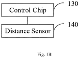
- Fig. 1B is a structural diagram of a doorframe assembly applicable in a microwave oven according to another exemplary embodiment.
- the control chip 130 is interconnected to the distance sensor 140.
- the distance sensor 140 is configured to detect a distance between the door sheet and the doorframe, and the control chip 130 is configured to control a direction of a current in the electrical magnet according to the distance detected by the distance sensor 140.
- the direction of the current flowed in the electrical magnet may be controlled by the control chip according to the distance determined by the distance sensor.
- the direction of the current flowed in the electrical magnet is related to the change of the distance between the door sheet of the microwave oven and the doorframe of the microwave oven, and thus it may solve a problem in the case where the pushing/pulling force applied by the user is insufficient to move the door, the user cannot push or pull the door of the microwave oven and thus unable to open/close the door normally. Accordingly, when the user pushes or pulls the door of the microwave oven, a force in the same direction of the door movement may be generated automatically by the microwave oven, thereby reducing the force required to push or pull the door.
- the doorframe assembly of the microwave oven may include but not limited to: the door sheet 110, the doorframe 120, the control chip 130, the distance sensor 140 and the door hinge.
- the door sheet 110 is connected to the doorframe 120 by the door hinge.
- the door sheet 110 includes at least one region opposite to the doorframe 120.
- a first region 111 of the door sheet 110 opposite to the doorframe 120 is provided with a first type of magnet.
- a second region 121 of the doorframe 120 opposite to the first region 111 is provided with a second type of magnet.
- the first type of magnet is one of a permanent magnet and an electrical magnet, and the second type of magnet is the other one of the permanent magnet and the electrical magnet.
- the control chip 130 is interconnected to the distance sensor 140.
- the distance sensor 140 is configured to detect a distance between the door sheet and the doorframe, and the control chip 130 is configured to control a direction of a current in the electrical magnet according to the distance detected by the distance sensor 140.
- the distance sensor 140 may be provided in the first region 111 or the second region 121, or may be provided in other positions, which is not limited in the present embodiment.
- Fig. 1C is a top view of a doorframe assembly applicable in a microwave oven according to an exemplary embodiment. As illustrated in Fig. 1C , the distance between the door sheet 110 and the doorframe 120 detected by the distance sensor 140 may be different according to different mounting positions of the distance sensor 140.
- the distance sensor 140 is disposed at a first mounting position 111a on the first region 111, and detects a relative distance between the door sheet 110 and the doorframe 120 at the first mounting position 111a.
- the relative distance is a vertical distance d1 between the first mounting position 111a and a plane in which the doorframe 120 is positioned.
- the distance sensor 140 is disposed at a second mounting position 121a on the second region 121 and detects a relative distance between the door sheet 110 and the doorframe 120 at the second mounting position 121a.
- the relative distance is a vertical distance d 2 between the second mounting position 121a and a plane in which the door sheet 110 is positioned.
- control chip 130 may be disposed in the distance sensor 140, or may be disposed at other positions, which is not limited herein.
- a handle portion 150 is provided on the door sheet 110.
- the doorframe assembly further includes a parameter acquisition device provided on the handle portion 150.
- the parameter acquisition device acquires environmental characteristic parameters at the handle portion 150 including at least one of temperature, brightness and pressure.
- the parameter acquisition device may be coupled to the distance sensor 140 by wiring, or is coupled to the control chip 130 by wiring.
- the direction of the current flowed in the electrical magnet may be controlled by the control chip according to the distance determined by the distance sensor.
- the direction of the current flowed in the electrical magnet is related to the change of the distance between the door sheet of the microwave oven and the doorframe of the microwave oven, and thus it may solve a problem in the case where the pushing/pulling force applied by the user is insufficient to move the door, the user cannot push or pull the door of the microwave oven and thus unable to open/close the door normally. Accordingly, when the user pushes or pulls the door of the microwave oven, a force in the same direction of the door movement may be generated automatically by the microwave oven, thereby reducing the force required to push or pull the door.
- Fig. 2 is a flow chart illustrating a method for controlling a doorframe assembly according to an exemplary embodiment. As illustrated in Fig. 2 , the method for controlling the doorframe assembly is applicable in the doorframe assembly illustrated in Fig. 1A , and may include the steps as follows.
- a current in a first direction is input to the electrical magnet when the control chip receives a first control signal transmitted from the distance sensor, so that an end of the electrical magnet facing the permanent magnet has a polarity opposite to that of the permanent magnet.
- the first control signal is generated when the distance sensor detects a decreasing distance between the door sheet and the doorframe.
- step 202 a current in a second direction is input to the electrical magnet when the control chip receives a second control signal transmitted from the distance sensor, so that the end of the electrical magnet facing the permanent magnet has a polarity the same as that of the permanent magnet.
- the second control signal is generated when the distance sensor detects an increasing distance between the door sheet and the doorframe.
- the end of the electrical magnet facing the permanent magnet may be controlled to have a polarity opposite to or the same as that of the permanent magnet, by receiving at the control chip the control signal transmitted from the distance sensor and then inputting to the electrical magnet the current in the direction corresponding to the control signal.
- the control signal is generated according to the detected change of the distance between the door sheet of the microwave oven and the doorframe of the microwave oven, and thus may solve a problem in the case where the pushing/pulling force applied by the user is insufficient to move the door, the user cannot push or pull the door of the microwave oven and thus unable to open/close the door normally. Accordingly, when the user pushes or pulls the door of the microwave oven, a force in the same direction of the door movement may be generated automatically by the microwave oven, thereby reducing the force required to push or pull the door.
- a parameter acquisition device may be provided at a handle portion of the microwave oven to avoid frequent detection of unnecessary distance change using the distance sensor.
- the control chip may transmit a detection-on instruction to the distance sensor for triggering the distance sensor to detect a distance change between the door sheet of the microwave oven and the doorframe of the microwave oven.
- Fig. 3 is a flow chart illustrating a method for controlling a doorframe assembly according to another exemplary embodiment. As illustrated in Fig. 3 , the method for controlling the doorframe assembly is applicable in the doorframe assembly illustrated in Fig. 1A , and may include the steps as follows.
- step 301 the control chip receives the detection-on signal transmitted from the parameter acquisition device.
- the detection-on signal is generated by the parameter acquisition device when the acquired parameter reaches the predetermined parameter level.
- the parameter acquisition device judges whether the acquired parameter reaches the predetermined parameter level, and transmits the detection-on signal to the control chip when the parameter reaches the predetermined parameter level.
- parameters 1 to 10 belong to the first parameter level
- parameters 11 to 20 belong to the second parameter level
- the predetermined parameter level is the second parameter level.
- the parameter is a parameter acquired by the parameter acquisition device corresponding to the environmental characteristic parameters at the handle portion of the microwave oven.
- the parameter corresponding to temperature may be a temperature value.
- the parameter corresponding to brightness may be a brightness value.
- the parameter corresponding to pressure may be a pressure value.
- step 302 the control chip transmits a detection-on instruction to the distance sensor.
- the detection-on instruction is an instruction for triggering the distance sensor to detect a distance change between the door sheet of the microwave oven and the doorframe of the microwave oven.
- step 303 a current in a first direction is input to the electrical magnet when the control chip receives a first control signal transmitted from the distance sensor, so that an end of the electrical magnet facing the permanent magnet has a polarity opposite to that of the permanent magnet.
- the first control signal is generated when the distance sensor detects a decreasing distance between the door sheet of the microwave oven and the doorframe of the microwave oven.
- attraction force may be generated between the electrical magnet and the permanent magnet. Accordingly, as the electrical magnet and the permanent magnet are disposed respectively at the first region on the door sheet of the microwave oven and the second region on the doorframe of the microwave oven, the door sheet of the microwave oven and the doorframe of the microwave oven may attract each other.
- the distance between the door sheet of the microwave oven and the doorframe of the microwave oven decreases, it may be determined that the door sheet is approaching the doorframe by external force. At this time, if there is attraction force between the door sheet of the microwave oven and the doorframe of the microwave oven, the external force required to push the door sheet towards the doorframe may be effectively reduced.
- step 304 a current in a second direction is input to the electrical magnet when the control chip receives a second control signal transmitted from the distance sensor, so that the end of the electrical magnet facing the permanent magnet has a polarity the same as that of the permanent magnet.
- the second control signal is generated when the distance sensor detects an increasing distance between the door sheet of the microwave oven and the doorframe of the microwave oven.
- the control chip controls the end of the electrical magnet facing the permanent magnet to have a polarity the same as that of the permanent magnet, repulsion force may be generated between the electrical magnet and the permanent magnet. Accordingly, as the electrical magnet and the permanent magnet are disposed respectively at the first region on the door sheet of the microwave oven and the second region on the doorframe of the microwave oven, the door sheet of the microwave oven and the doorframe of the microwave oven may repulse each other.
- the distance between the door sheet of the microwave oven and the doorframe of the microwave oven increases, it may be determined that the door sheet is moving away from the doorframe by external force. At this time, if there is repulsion force between the door sheet of the microwave oven and the doorframe of the microwave oven, the external force required to push the door sheet away from the doorframe may be effectively reduced.
- the first direction differs from the second direction in the present embodiment.
- step 305 the control chip receives a third control signal transmitted from the distance sensor and carrying an acceleration of the door sheet.
- the third control signal is generated when the distance sensor detects a decreasing distance between the door sheet and the doorframe and a detected acceleration of the door sheet is greater than an acceleration threshold.
- step 306 the control chip queries a predetermined current value corresponding to the acceleration of the door sheet.
- the acceleration of the door sheet is proportional to the predetermined current value.
- step 307 the control chip inputs a current in the second direction having the predetermined current value to the electrical magnet.
- an electromagnetic force generated by the electrical magnet is proportional to the current flowing in the electrical magnet. Accordingly, the larger the current value of the current flowing in the second direction input to the electrical magnet is, the larger the electromagnetic force generated by the electrical magnet becomes, and thus the larger the repulsion force between the door sheet of the microwave oven and the doorframe of the microwave oven becomes.
- the end of the electrical magnet facing the permanent magnet may be controlled to have a polarity opposite to or the same as that of the permanent magnet, by receiving at the control chip the control signal transmitted from the distance sensor and then inputting to the electrical magnet the current in the direction corresponding to the control signal.
- the control signal is generated according to the detected change of the distance between the door sheet of the microwave oven and the doorframe of the microwave oven, and thus may solve a problem in the case where the pushing/pulling force applied by the user is insufficient to move the door, the user cannot push or pull the door of the microwave oven and thus unable to open/close the door normally. Accordingly, when the user pushes or pulls the door of the microwave oven, a force in the same direction of the door movement may be generated automatically by the microwave oven, thereby reducing the force required to push or pull the door.
- the control chip inputs the current having the predetermined current value in the second direction to the electrical magnet when the distance between the door sheet and the doorframe is decreased and the acceleration of the door sheet is greater than the acceleration threshold, and since the acceleration of the door sheet of the microwave oven is proportional to the predetermined current value when the acceleration of the door sheet of the microwave oven is greater than the acceleration threshold, the control chip may control the electrical magnet to generate a repulsion force between the electrical magnet and the permanent magnet when the door sheet of the microwave oven is closed too fast, thereby preventing damage to the door sheet due to impacts between the door sheet of the microwave oven and the doorframe of the microwave oven.
- the device embodiments may be configured to perform the method embodiments of the present disclosure. Relevant contents that are not disclosure in detail in the device embodiments may be referred to some explanations in the method embodiments.
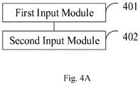
- Fig. 4A is a block diagram of a device for controlling a doorframe assembly according to an exemplary embodiment.
- the device is applicable in a microwave oven.
- the device for controlling a doorframe assembly is applicable in the doorframe assembly illustrated in Fig. 1A .
- the device for controlling the doorframe assembly may include but not limited to: a first input module 401 and a second input module 402.
- the first input module 401 is configured to input a current in a first direction to the electrical magnet when the control chip receives a first control signal transmitted from the distance sensor, so that an end of the electrical magnet facing the permanent magnet has a polarity opposite to that of the permanent magnet.
- the first control signal is generated when the distance sensor detects a decreasing distance between the door sheet and the doorframe.
- attraction force may be generated between the electrical magnet and the permanent magnet. Accordingly, as the electrical magnet and the permanent magnet are disposed respectively at the first region on the door sheet of the microwave oven and the second region on the doorframe of the microwave oven, the door sheet of the microwave oven and the doorframe of the microwave oven may attract each other.
- the distance between the door sheet of the microwave oven and the doorframe of the microwave oven decreases, it may be determined that the door sheet is approaching the doorframe by external force. At this time, if there is attraction force between the door sheet of the microwave oven and the doorframe of the microwave oven, the external force required to push the door sheet towards the doorframe may be effectively reduced.
- the second input module 402 is configured to input a current in a second direction to the electrical magnet when the control chip receives a second control signal transmitted from the distance sensor, so that the end of the electrical magnet facing the permanent magnet has a polarity the same as that of the permanent magnet.
- the second control signal is generated when the distance sensor detects an increasing distance between the door sheet and the doorframe.
- the first direction differs from the second direction.
- the control chip controls the end of the electrical magnet facing the permanent magnet to have a polarity the same as that of the permanent magnet, repulsion force may be generated between the electrical magnet and the permanent magnet. Accordingly, as the electrical magnet and the permanent magnet are disposed respectively at the first region on the door sheet of the microwave oven and the second region on the doorframe of the microwave oven, the door sheet of the microwave oven and the doorframe of the microwave oven may repulse each other.
- the distance between the door sheet of the microwave oven and the doorframe of the microwave oven increases, it may be determined that the door sheet is moving away from the doorframe by external force. At this time, if there is repulsion force between the door sheet of the microwave oven and the doorframe of the microwave oven, the external force required to push the door sheet away from the doorframe may be effectively reduced.
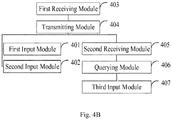
- Fig. 4B is a block diagram of a device for controlling a doorframe assembly according to another exemplary embodiment
- the device further includes a first receiving module 403 and a transmitting module 404.
- the first receiving module 403 is configured to receive a detection-on signal transmitted from the parameter acquisition device.
- the detection-on signal is generated by the parameter acquisition device when an acquired parameter reaches a predetermined parameter level.
- the parameter acquisition device judges whether the acquired parameter reaches the predetermined parameter level, and transmits the detection-on signal to the control chip when the parameter reaches the predetermined parameter level.
- the parameter is a parameter acquired by the parameter acquisition device corresponding to the environmental characteristic parameters at the handle portion of the microwave oven.
- the parameter corresponding to temperature may be a temperature value.
- the parameter corresponding to brightness may be a brightness value.
- the parameter corresponding to pressure may be a pressure value.
- the transmitting module 404 is configured to transmit, to the distance sensor, a detection-on instruction for triggering the distance sensor to detect a distance change between the door sheet and the doorframe.
- the device further includes a second receiving module 405, a querying module 406 and a third input module 407.
- the second receiving module 405 is configured to receive a third control signal transmitted from the distance sensor and carrying an acceleration of the door sheet.
- the third control signal is generated when the distance sensor detects a decreasing distance between the door sheet and the doorframe and a detected acceleration of the door sheet is greater than an acceleration threshold.
- the querying module 406 is configured to query a predetermined current value corresponding to the acceleration of the door sheet.
- the acceleration of the door sheet is proportional to the predetermined current value.
- the third input module 407 is configured to input a current in the second direction having the predetermined current value to the electrical magnet.
- an electromagnetic force generated by the electrical magnet is proportional to the current flowing in the electrical magnet. Accordingly, the larger the current value of the current flowing in the second direction input to the electrical magnet is, the larger the electromagnetic force generated by the electrical magnet becomes, and thus the larger the repulsion force between the door sheet of the microwave oven and the doorframe of the microwave oven becomes.
- the end of the electrical magnet facing the permanent magnet may be controlled to have a polarity opposite to or the same as that of the permanent magnet, by receiving at the control chip the control signal transmitted from the distance sensor and then inputting to the electrical magnet the current in the direction corresponding to the control signal.
- the control signal is generated according to the detected change of the distance between the door sheet of the microwave oven and the doorframe of the microwave oven, and thus may solve a problem in the case where the pushing/pulling force applied by the user is insufficient to move the door, the user cannot push or pull the door of the microwave oven and thus unable to open/close the door normally. Accordingly, when the user pushes or pulls the door of the microwave oven, a force in the same direction of the door movement may be generated automatically by the microwave oven, thereby reducing the force required to push or pull the door.
- the end of the electrical magnet facing the permanent magnet may be controlled to have a polarity opposite to or the same as that of the permanent magnet, by receiving at the control chip the control signal transmitted from the distance sensor and then inputting to the electrical magnet the current in the direction corresponding to the control signal.
- the control signal is generated according to the detected change of the distance between the door sheet of the microwave oven and the doorframe of the microwave oven, and thus may solve a problem in the case where the pushing/pulling force applied by the user is insufficient to move the door, the user cannot push or pull the door of the microwave oven and thus unable to open/close the door normally. Accordingly, when the user pushes or pulls the door of the microwave oven, a force in the same direction of the door movement may be generated automatically by the microwave oven, thereby reducing the force required to push or pull the door.
- the detection-on instruction is transmitted from the control chip to the distance sensor after the detection-on signal transmitted from the parameter acquisition device is received, and since the detection-on signal is generated by the parameter acquisition device when the acquired parameter reaches the predetermined parameter level, the distance between the door sheet of the microwave oven and the doorframe of the microwave oven is detected only when the door sheet of the microwave oven is operated by the user, thereby reducing power consumption of the doorframe assembly.
- the control chip inputs the current having the predetermined current value in the second direction to the electrical magnet when the distance between the door sheet and the doorframe is decreased and the acceleration of the door sheet is greater than the acceleration threshold, and since the acceleration of the door sheet of the microwave oven is proportional to the predetermined current value when the acceleration of the door sheet of the microwave oven is greater than the acceleration threshold, the control chip may control the electrical magnet to generate a repulsion force between the electrical magnet and the permanent magnet when the door sheet of the microwave oven is closed too fast, thereby preventing damage to the door sheet due to impacts between the door sheet of the microwave oven and the doorframe of the microwave oven.
Landscapes
- Physics & Mathematics (AREA)
- Electromagnetism (AREA)
- Engineering & Computer Science (AREA)
- Power Engineering (AREA)
- Mechanical Engineering (AREA)
- Electric Ovens (AREA)
- Control Of High-Frequency Heating Circuits (AREA)
- Constitution Of High-Frequency Heating (AREA)
- Special Wing (AREA)
Abstract
Description
- The present disclosure generally relates to the field of smart home, and more particularly, to a doorframe assembly for a microwave oven, and a method and a device for controlling the doorframe assembly.
- Generally, a door of a microwave oven may be opened/closed by pulling/pushing the door manually by a user.
- In the case where the pushing/pulling force applied by the user is insufficient to move the door, the user may be unable to push or pull the door of the microwave oven and thus may be unable to open/close the door normally.
- The present disclosure provides a doorframe assembly for a microwave oven, and a method and a device for controlling the doorframe assembly. The technical solution is as below:
- According to a first aspect of the present invention, there is provided a doorframe assembly for a microwave oven including: a door sheet; and a doorframe connected to the door sheet by a door hinge, wherein the door sheet includes at least one region opposite to the doorframe, a first region of the door sheet opposite to the doorframe is provided with a first type of magnet, a second region of the doorframe opposite to the first region is provided with a second type of magnet, the first type of magnet is one of a permanent magnet and an electrical magnet, and the second type of magnet is the other one of the permanent magnet and the electrical magnet, and wherein the doorframe assembly further includes a control chip and a distance sensor that are interconnected, the distance sensor is configured to detect a distance between the door sheet and the doorframe, and the control chip is configured to control a direction of a current in the electrical magnet according to the distance detected by the distance sensor. By connecting the control chip with the distance sensor and detecting the distance between the door sheet of the microwave oven and the doorframe of the microwave oven using the distance sensor, the direction of the current flowed in the electrical magnet may be controlled by the control chip according to the distance determined by the distance sensor. The direction of the current flowed in the electrical magnet is related to the change of the distance between the door sheet of the microwave oven and the doorframe of the microwave oven, and thus it may solve a problem in the case where the pushing/pulling force applied by the user is insufficient to move the door, the user cannot push or pull the door of the microwave oven and thus unable to open/close the door normally. Accordingly, when the user pushes or pulls the door of the microwave oven, a force in the same direction of the door movement may be generated automatically by the microwave oven, thereby reducing the force required to push or pull the door.
- Advantageously, the distance sensor is disposed at a first mounting position on the first region and detects a relative distance between the door sheet and the doorframe at the first mounting position, and wherein the relative distance is a vertical distance between the first mounting position and a plane in which the doorframe is positioned; or, the distance sensor is disposed at a second mounting position on the second region and detects a relative distance between the door sheet and the doorframe at the second mounting position, and wherein the relative distance is a vertical distance between the second mounting position and a plane in which the door sheet is positioned.
- Advantageously, the door sheet is provided with a handle portion, and a parameter acquisition device, configured to acquire environmental characteristic parameters including at least one of temperature, brightness and pressure, is provided on the handle portion.
- Advantageously, the parameter acquisition device is coupled to the distance sensor by wiring, or is coupled to the control chip by wiring.
- According to a second aspect of the present invention, there is provided a method for controlling a doorframe assembly, the method being applicable in a microwave oven including a doorframe assembly according to the first aspect of the present disclosure, and the method including: inputting a current in a first direction to the electrical magnet when the control chip receives a first control signal transmitted from the distance sensor, so that an end of the electrical magnet facing the permanent magnet has a polarity opposite to that of the permanent magnet, the first control signal being generated when the distance sensor detects a decreasing distance between the door sheet and the doorframe; and inputting a current in a second direction to the electrical magnet when the control chip receives a second control signal transmitted from the distance sensor, so that the end of the electrical magnet facing the permanent magnet has a polarity the same as that of the permanent magnet, the second control signal being generated when the distance sensor detects an increasing distance between the door sheet and the doorframe, wherein the first direction differs from the second direction. The end of the electrical magnet facing the permanent magnet may be controlled to have a polarity opposite to or the same as that of the permanent magnet, by receiving at the control chip the control signal transmitted from the distance sensor and then inputting to the electrical magnet the current in the direction corresponding to the control signal. The control signal is generated according to the detected change of the distance between the door sheet of the microwave oven and the doorframe of the microwave oven, and thus it may solve a problem in the case where the pushing/pulling force applied by the user is insufficient to move the door, the user cannot push or pull the door of the microwave oven and thus unable to open/close the door normally. Accordingly, when the user pushes or pulls the door of the microwave oven, a force in the same direction of the door movement may be generated automatically by the microwave oven, thereby reducing the force required to push or pull the door.
- Advantageously, the method further includes: receiving, at the control chip, a detection-on signal transmitted from the parameter acquisition device, the detection-on signal being generated by the parameter acquisition device when an acquired parameter reaches a predetermined parameter level; and transmitting, from the control chip to the distance sensor, a detection-on instruction for triggering the distance sensor to detect a distance change between the door sheet and the doorframe. The detection-on instruction is transmitted from the control chip to the distance sensor after the detection-on signal transmitted from the parameter acquisition device is received, and since the detection-on signal is generated by the parameter acquisition device when the acquired parameter reaches the predetermined parameter level, the distance between the door sheet of the microwave oven and the doorframe of the microwave oven is detected only when the door sheet of the microwave oven is operated by the user, thereby reducing power consumption of the doorframe assembly.
- Advantageously, the method further includes: receiving, at the control chip, a third control signal transmitted from the distance sensor and carrying an acceleration of the door sheet, the third control signal being generated when the distance sensor detects a decreasing distance between the door sheet and the doorframe and a detected acceleration of the door sheet is greater than an acceleration threshold; querying, by the control chip, a predetermined current value corresponding to the acceleration of the door sheet, the acceleration of the door sheet being proportional to the predetermined current value; and inputting, by the control chip, a current in the second direction having the predetermined current value to the electrical magnet. The control chip inputs the current having the predetermined current value in the second direction to the electrical magnet when the distance between the door sheet and the doorframe is decreased and the acceleration of the door sheet is greater than the acceleration threshold, and since the acceleration of the door sheet of the microwave oven is proportional to the predetermined current value when the acceleration of the door sheet of the microwave oven is greater than the acceleration threshold, the control chip may control the electrical magnet to generate a repulsion force between the electrical magnet and the permanent magnet when the door sheet of the microwave oven is closed too fast, thereby preventing damage to the door sheet due to impacts between the door sheet of the microwave oven and the doorframe of the microwave oven.
- According to a third aspect of the present invention, there is provided a device for controlling a doorframe assembly, the device being applicable in a microwave oven including a doorframe assembly according to the first aspect of the present disclosure, the device including: a first input module, configured to input a current in a first direction to the electrical magnet when the control chip receives a first control signal transmitted from the distance sensor, so that an end of the electrical magnet facing the permanent magnet has a polarity opposite to that of the permanent magnet, the first control signal being generated when the distance sensor detects a decreasing distance between the door sheet and the doorframe; and a second input module, configured to input a current in a second direction to the electrical magnet when the control chip receives a second control signal transmitted from the distance sensor, so that the end of the electrical magnet facing the permanent magnet has a polarity the same as that of the permanent magnet, the second control signal being generated when the distance sensor detects an increasing distance between the door sheet and the doorframe, wherein the first direction differs from the second direction.
- Advantageously, the device further includes: a first receiving module, configured to receive a detection-on signal transmitted from the parameter acquisition device, the detection-on signal being generated by the parameter acquisition device when an acquired parameter reaches a predetermined parameter level; and a transmitting module, configured to transmit, to the distance sensor, a detection-on instruction for triggering the distance sensor to detect a distance change between the door sheet and the doorframe.
- Advantageously, the device further includes a second receiving module, configured to receive a third control signal transmitted from the distance sensor and carrying an acceleration of the door sheet, the third control signal being generated when the distance sensor detects a decreasing distance between the door sheet and the doorframe and a detected acceleration of the door sheet is greater than an acceleration threshold; a querying module, configured to query a predetermined current value corresponding to the acceleration of the door sheet, the acceleration of the door sheet being proportional to the predetermined current value; and a third input module, configured to input a current in the second direction having the predetermined current value to the electrical magnet.
- According to a fourth aspect of the present invention, there is also provided a computer program for executing the steps of a method for controlling a doorframe assembly as described above when this program is executed by a processor.
- This program can use any programming language and take the form of source code, object code or a code intermediate between source code and object code, such as a partially compiled form, or any other desirable form.
- The present disclosure is also directed to a computer-readable information medium containing instructions of a computer program as described above.
- The information medium can be any entity or device capable of storing the program. For example, the support can include storage means such as a ROM, for example a CD ROM or a microelectronic circuit ROM, or magnetic storage means, for example a diskette (floppy disk) or a hard disk.
- Advantageously, the information medium can be an integrated circuit in which the program is incorporated, the circuit being adapted to execute the method in question or to be used in its execution.
- It is to be understood that both the foregoing general description and the following detailed description are exemplary only and are not restrictive of the present disclosure.
- The accompanying drawings, which are incorporated in and constitute a part of this specification, illustrate embodiments consistent with the present disclosure and, together with the description, serve to explain the principles of the present disclosure.
-
Fig. 1A is a structural diagram of a doorframe assembly applicable in a microwave oven according to an exemplary embodiment; -
Fig. 1B is a structural diagram of a doorframe assembly applicable in a microwave oven according to another exemplary embodiment; -
Fig. 1C is a top view of a doorframe assembly applicable in a microwave oven according to an exemplary embodiment; -
Fig. 2 is a flow chart illustrating a method for controlling a doorframe assembly according to an exemplary embodiment; -
Fig. 3 is a flow chart illustrating a method for controlling a doorframe assembly according to another exemplary embodiment; -
Fig. 4A is a block diagram of a device for controlling a doorframe assembly according to an exemplary embodiment; and -
Fig. 4B is a block diagram of a device for controlling a doorframe assembly according to another exemplary embodiment. - Reference will now be made in detail to exemplary embodiments, examples of which are illustrated in the accompanying drawings. The following description refers to the accompanying drawings in which the same numbers in different drawings represent the same or similar elements unless otherwise represented. The implementations set forth in the following description of exemplary embodiments do not represent all implementations consistent with the present disclosure. Instead, they are merely examples of devices and methods consistent with aspects related to the present disclosure as recited in the appended claims.
-
Fig. 1A is a structural diagram of a doorframe assembly applicable in a microwave oven according to an exemplary embodiment. The doorframe assembly of the microwave oven may include but not limited to: adoor sheet 110, adoorframe 120, acontrol chip 130, adistance sensor 140 and a door hinge. - As illustrated in
Fig. 1A , thedoor sheet 110 is connected to thedoorframe 120 by the door hinge. Thedoor sheet 110 includes at least one region opposite to thedoorframe 120. Afirst region 111 of thedoor sheet 110 opposite to thedoorframe 120 is provided with a first type of magnet. Asecond region 121 of thedoorframe 120 opposite to thefirst region 111 is provided with a second type of magnet. The first type of magnet is one of a permanent magnet and an electrical magnet, and the second type of magnet is the other one of the permanent magnet and the electrical magnet. -
Fig. 1B is a structural diagram of a doorframe assembly applicable in a microwave oven according to another exemplary embodiment. As illustrated inFig. 1B , thecontrol chip 130 is interconnected to thedistance sensor 140. Thedistance sensor 140 is configured to detect a distance between the door sheet and the doorframe, and thecontrol chip 130 is configured to control a direction of a current in the electrical magnet according to the distance detected by thedistance sensor 140. - Accordingly, according to the doorframe assembly applicable in a microwave oven according to embodiments of the present disclosure, by connecting the control chip with the distance sensor and detecting the distance between the door sheet and the doorframe using the distance sensor, the direction of the current flowed in the electrical magnet may be controlled by the control chip according to the distance determined by the distance sensor. The direction of the current flowed in the electrical magnet is related to the change of the distance between the door sheet of the microwave oven and the doorframe of the microwave oven, and thus it may solve a problem in the case where the pushing/pulling force applied by the user is insufficient to move the door, the user cannot push or pull the door of the microwave oven and thus unable to open/close the door normally. Accordingly, when the user pushes or pulls the door of the microwave oven, a force in the same direction of the door movement may be generated automatically by the microwave oven, thereby reducing the force required to push or pull the door.
- Continuing referring to
Fig. 1A , the doorframe assembly of the microwave oven may include but not limited to: thedoor sheet 110, thedoorframe 120, thecontrol chip 130, thedistance sensor 140 and the door hinge. - The
door sheet 110 is connected to thedoorframe 120 by the door hinge. Thedoor sheet 110 includes at least one region opposite to thedoorframe 120. Afirst region 111 of thedoor sheet 110 opposite to thedoorframe 120 is provided with a first type of magnet. Asecond region 121 of thedoorframe 120 opposite to thefirst region 111 is provided with a second type of magnet. The first type of magnet is one of a permanent magnet and an electrical magnet, and the second type of magnet is the other one of the permanent magnet and the electrical magnet. - As illustrated in
Fig. 1B , thecontrol chip 130 is interconnected to thedistance sensor 140. Thedistance sensor 140 is configured to detect a distance between the door sheet and the doorframe, and thecontrol chip 130 is configured to control a direction of a current in the electrical magnet according to the distance detected by thedistance sensor 140. - Alternatively, referring to
Figs. 1A and1B , thedistance sensor 140 may be provided in thefirst region 111 or thesecond region 121, or may be provided in other positions, which is not limited in the present embodiment. -
Fig. 1C is a top view of a doorframe assembly applicable in a microwave oven according to an exemplary embodiment. As illustrated inFig. 1C , the distance between thedoor sheet 110 and thedoorframe 120 detected by thedistance sensor 140 may be different according to different mounting positions of thedistance sensor 140. - In part (1) of
Fig. 1C , thedistance sensor 140 is disposed at afirst mounting position 111a on thefirst region 111, and detects a relative distance between thedoor sheet 110 and thedoorframe 120 at thefirst mounting position 111a. The relative distance is a vertical distance d1 between thefirst mounting position 111a and a plane in which thedoorframe 120 is positioned. - In part (2) of
Fig. 1C , thedistance sensor 140 is disposed at asecond mounting position 121a on thesecond region 121 and detects a relative distance between thedoor sheet 110 and thedoorframe 120 at thesecond mounting position 121a. The relative distance is a vertical distance d2 between thesecond mounting position 121a and a plane in which thedoor sheet 110 is positioned. - Alternatively, the
control chip 130 may be disposed in thedistance sensor 140, or may be disposed at other positions, which is not limited herein. - Alternatively, continuing referring to
Fig. 1A , ahandle portion 150 is provided on thedoor sheet 110. The doorframe assembly further includes a parameter acquisition device provided on thehandle portion 150. - Herein, the parameter acquisition device acquires environmental characteristic parameters at the
handle portion 150 including at least one of temperature, brightness and pressure. - According to the present embodiment, the parameter acquisition device may be coupled to the
distance sensor 140 by wiring, or is coupled to thecontrol chip 130 by wiring. - Accordingly, according to the doorframe assembly applicable in a microwave oven according to embodiments of the present disclosure, by connecting the control chip with the distance sensor and detecting the distance between the door sheet and the doorframe using the distance sensor, the direction of the current flowed in the electrical magnet may be controlled by the control chip according to the distance determined by the distance sensor. The direction of the current flowed in the electrical magnet is related to the change of the distance between the door sheet of the microwave oven and the doorframe of the microwave oven, and thus it may solve a problem in the case where the pushing/pulling force applied by the user is insufficient to move the door, the user cannot push or pull the door of the microwave oven and thus unable to open/close the door normally. Accordingly, when the user pushes or pulls the door of the microwave oven, a force in the same direction of the door movement may be generated automatically by the microwave oven, thereby reducing the force required to push or pull the door.
-
Fig. 2 is a flow chart illustrating a method for controlling a doorframe assembly according to an exemplary embodiment. As illustrated inFig. 2 , the method for controlling the doorframe assembly is applicable in the doorframe assembly illustrated inFig. 1A , and may include the steps as follows. - In
step 201, a current in a first direction is input to the electrical magnet when the control chip receives a first control signal transmitted from the distance sensor, so that an end of the electrical magnet facing the permanent magnet has a polarity opposite to that of the permanent magnet. The first control signal is generated when the distance sensor detects a decreasing distance between the door sheet and the doorframe. - In
step 202, a current in a second direction is input to the electrical magnet when the control chip receives a second control signal transmitted from the distance sensor, so that the end of the electrical magnet facing the permanent magnet has a polarity the same as that of the permanent magnet. The second control signal is generated when the distance sensor detects an increasing distance between the door sheet and the doorframe. - Accordingly, according to the method for controlling a doorframe assembly according to embodiments of the present disclosure, the end of the electrical magnet facing the permanent magnet may be controlled to have a polarity opposite to or the same as that of the permanent magnet, by receiving at the control chip the control signal transmitted from the distance sensor and then inputting to the electrical magnet the current in the direction corresponding to the control signal. The control signal is generated according to the detected change of the distance between the door sheet of the microwave oven and the doorframe of the microwave oven, and thus may solve a problem in the case where the pushing/pulling force applied by the user is insufficient to move the door, the user cannot push or pull the door of the microwave oven and thus unable to open/close the door normally. Accordingly, when the user pushes or pulls the door of the microwave oven, a force in the same direction of the door movement may be generated automatically by the microwave oven, thereby reducing the force required to push or pull the door.
- In daily life, the distance between the door frame of the microwave oven and the doorframe of the microwave oven may be changed due to natural factors such as wind force. A parameter acquisition device may be provided at a handle portion of the microwave oven to avoid frequent detection of unnecessary distance change using the distance sensor. When the control chip receives a detection-on signal transmitted from the parameter acquisition device, the control chip may transmit a detection-on instruction to the distance sensor for triggering the distance sensor to detect a distance change between the door sheet of the microwave oven and the doorframe of the microwave oven. The detection-on signal is generated by the parameter acquisition device when the acquired parameter reaches the predetermined parameter level, the distance between the door sheet of the microwave oven and the doorframe of the microwave oven is detected only when the door sheet of the microwave oven is operated by the user, thereby reducing power consumption of the doorframe assembly.
Fig. 3 is a flow chart illustrating a method for controlling a doorframe assembly according to another exemplary embodiment. As illustrated inFig. 3 , the method for controlling the doorframe assembly is applicable in the doorframe assembly illustrated inFig. 1A , and may include the steps as follows. - In
step 301, the control chip receives the detection-on signal transmitted from the parameter acquisition device. - Herein, the detection-on signal is generated by the parameter acquisition device when the acquired parameter reaches the predetermined parameter level.
- When a parameter is acquired by the parameter acquisition device, the parameter acquisition device judges whether the acquired parameter reaches the predetermined parameter level, and transmits the detection-on signal to the control chip when the parameter reaches the predetermined parameter level.
- For example, assuming that
parameters 1 to 10 belong to the first parameter level, parameters 11 to 20 belong to the second parameter level, and the predetermined parameter level is the second parameter level. When the parameter acquisition device acquires a parameter 9, it is judged that the parameter 9 does not reach the second parameter level, and thus no further operation is performed. When the parameter acquisition device acquires a parameter 13, it is judged that the parameter 13 reaches the second parameter level, and thus the detection-on signal is transmitted to the control chip. - Herein, the parameter is a parameter acquired by the parameter acquisition device corresponding to the environmental characteristic parameters at the handle portion of the microwave oven.
- When the environmental characteristic parameter is temperature, the parameter corresponding to temperature may be a temperature value. When the environmental characteristic parameter is brightness, the parameter corresponding to brightness may be a brightness value. When the environmental characteristic parameter is pressure, the parameter corresponding to pressure may be a pressure value.
- It should be noted that, detailed parameter level is not limited in the present embodiment.
- In
step 302, the control chip transmits a detection-on instruction to the distance sensor. - Herein, the detection-on instruction is an instruction for triggering the distance sensor to detect a distance change between the door sheet of the microwave oven and the doorframe of the microwave oven.
- In
step 303, a current in a first direction is input to the electrical magnet when the control chip receives a first control signal transmitted from the distance sensor, so that an end of the electrical magnet facing the permanent magnet has a polarity opposite to that of the permanent magnet. - Herein, the first control signal is generated when the distance sensor detects a decreasing distance between the door sheet of the microwave oven and the doorframe of the microwave oven.
- When the control chip controls the end of the electrical magnet facing the permanent magnet to have a polarity opposite to that of the permanent magnet, attraction force may be generated between the electrical magnet and the permanent magnet. Accordingly, as the electrical magnet and the permanent magnet are disposed respectively at the first region on the door sheet of the microwave oven and the second region on the doorframe of the microwave oven, the door sheet of the microwave oven and the doorframe of the microwave oven may attract each other.
- When the distance between the door sheet of the microwave oven and the doorframe of the microwave oven decreases, it may be determined that the door sheet is approaching the doorframe by external force. At this time, if there is attraction force between the door sheet of the microwave oven and the doorframe of the microwave oven, the external force required to push the door sheet towards the doorframe may be effectively reduced.
- In
step 304, a current in a second direction is input to the electrical magnet when the control chip receives a second control signal transmitted from the distance sensor, so that the end of the electrical magnet facing the permanent magnet has a polarity the same as that of the permanent magnet. - Herein, the second control signal is generated when the distance sensor detects an increasing distance between the door sheet of the microwave oven and the doorframe of the microwave oven.
- When the control chip controls the end of the electrical magnet facing the permanent magnet to have a polarity the same as that of the permanent magnet, repulsion force may be generated between the electrical magnet and the permanent magnet. Accordingly, as the electrical magnet and the permanent magnet are disposed respectively at the first region on the door sheet of the microwave oven and the second region on the doorframe of the microwave oven, the door sheet of the microwave oven and the doorframe of the microwave oven may repulse each other.
- When the distance between the door sheet of the microwave oven and the doorframe of the microwave oven increases, it may be determined that the door sheet is moving away from the doorframe by external force. At this time, if there is repulsion force between the door sheet of the microwave oven and the doorframe of the microwave oven, the external force required to push the door sheet away from the doorframe may be effectively reduced.
- It should be noted that, the first direction differs from the second direction in the present embodiment.
- In
step 305, the control chip receives a third control signal transmitted from the distance sensor and carrying an acceleration of the door sheet. - Herein, the third control signal is generated when the distance sensor detects a decreasing distance between the door sheet and the doorframe and a detected acceleration of the door sheet is greater than an acceleration threshold.
- It should be noted that the detailed magnitude of the acceleration threshold is not limited in the present embodiment.
- In
step 306, the control chip queries a predetermined current value corresponding to the acceleration of the door sheet. - Herein, the acceleration of the door sheet is proportional to the predetermined current value. The larger the acceleration of the door sheet of the microwave oven is, the larger the predetermined current value corresponding to the acceleration of the door sheet becomes.
- In
step 307, the control chip inputs a current in the second direction having the predetermined current value to the electrical magnet. - As can be seen from the definitional equation of intensification of magnetic induction, i.e., F=B×I×L, an electromagnetic force generated by the electrical magnet is proportional to the current flowing in the electrical magnet. Accordingly, the larger the current value of the current flowing in the second direction input to the electrical magnet is, the larger the electromagnetic force generated by the electrical magnet becomes, and thus the larger the repulsion force between the door sheet of the microwave oven and the doorframe of the microwave oven becomes.
- Accordingly, according to the method for controlling a doorframe assembly according to embodiments of the present disclosure, the end of the electrical magnet facing the permanent magnet may be controlled to have a polarity opposite to or the same as that of the permanent magnet, by receiving at the control chip the control signal transmitted from the distance sensor and then inputting to the electrical magnet the current in the direction corresponding to the control signal. The control signal is generated according to the detected change of the distance between the door sheet of the microwave oven and the doorframe of the microwave oven, and thus may solve a problem in the case where the pushing/pulling force applied by the user is insufficient to move the door, the user cannot push or pull the door of the microwave oven and thus unable to open/close the door normally. Accordingly, when the user pushes or pulls the door of the microwave oven, a force in the same direction of the door movement may be generated automatically by the microwave oven, thereby reducing the force required to push or pull the door.
- In the present embodiment, the control chip inputs the current having the predetermined current value in the second direction to the electrical magnet when the distance between the door sheet and the doorframe is decreased and the acceleration of the door sheet is greater than the acceleration threshold, and since the acceleration of the door sheet of the microwave oven is proportional to the predetermined current value when the acceleration of the door sheet of the microwave oven is greater than the acceleration threshold, the control chip may control the electrical magnet to generate a repulsion force between the electrical magnet and the permanent magnet when the door sheet of the microwave oven is closed too fast, thereby preventing damage to the door sheet due to impacts between the door sheet of the microwave oven and the doorframe of the microwave oven.
- Hereinafter, device embodiments of the present disclosure will be described. The device embodiments may be configured to perform the method embodiments of the present disclosure. Relevant contents that are not disclosure in detail in the device embodiments may be referred to some explanations in the method embodiments.
-
Fig. 4A is a block diagram of a device for controlling a doorframe assembly according to an exemplary embodiment. The device is applicable in a microwave oven. As illustrated inFig. 4A , the device for controlling a doorframe assembly is applicable in the doorframe assembly illustrated inFig. 1A . The device for controlling the doorframe assembly may include but not limited to: afirst input module 401 and asecond input module 402. - The
first input module 401 is configured to input a current in a first direction to the electrical magnet when the control chip receives a first control signal transmitted from the distance sensor, so that an end of the electrical magnet facing the permanent magnet has a polarity opposite to that of the permanent magnet. The first control signal is generated when the distance sensor detects a decreasing distance between the door sheet and the doorframe. - When the control chip controls the end of the electrical magnet facing the permanent magnet to have a polarity opposite to that of the permanent magnet, attraction force may be generated between the electrical magnet and the permanent magnet. Accordingly, as the electrical magnet and the permanent magnet are disposed respectively at the first region on the door sheet of the microwave oven and the second region on the doorframe of the microwave oven, the door sheet of the microwave oven and the doorframe of the microwave oven may attract each other.
- When the distance between the door sheet of the microwave oven and the doorframe of the microwave oven decreases, it may be determined that the door sheet is approaching the doorframe by external force. At this time, if there is attraction force between the door sheet of the microwave oven and the doorframe of the microwave oven, the external force required to push the door sheet towards the doorframe may be effectively reduced.
- The
second input module 402 is configured to input a current in a second direction to the electrical magnet when the control chip receives a second control signal transmitted from the distance sensor, so that the end of the electrical magnet facing the permanent magnet has a polarity the same as that of the permanent magnet. The second control signal is generated when the distance sensor detects an increasing distance between the door sheet and the doorframe. The first direction differs from the second direction. - When the control chip controls the end of the electrical magnet facing the permanent magnet to have a polarity the same as that of the permanent magnet, repulsion force may be generated between the electrical magnet and the permanent magnet. Accordingly, as the electrical magnet and the permanent magnet are disposed respectively at the first region on the door sheet of the microwave oven and the second region on the doorframe of the microwave oven, the door sheet of the microwave oven and the doorframe of the microwave oven may repulse each other.
- When the distance between the door sheet of the microwave oven and the doorframe of the microwave oven increases, it may be determined that the door sheet is moving away from the doorframe by external force. At this time, if there is repulsion force between the door sheet of the microwave oven and the doorframe of the microwave oven, the external force required to push the door sheet away from the doorframe may be effectively reduced.
- In a further possible implementation, as illustrated in
Fig. 4B , which is a block diagram of a device for controlling a doorframe assembly according to another exemplary embodiment, the device further includes afirst receiving module 403 and atransmitting module 404. - The
first receiving module 403 is configured to receive a detection-on signal transmitted from the parameter acquisition device. The detection-on signal is generated by the parameter acquisition device when an acquired parameter reaches a predetermined parameter level. - When a parameter is acquired by the parameter acquisition device, the parameter acquisition device judges whether the acquired parameter reaches the predetermined parameter level, and transmits the detection-on signal to the control chip when the parameter reaches the predetermined parameter level.
- Herein, the parameter is a parameter acquired by the parameter acquisition device corresponding to the environmental characteristic parameters at the handle portion of the microwave oven.
- When the environmental characteristic parameter is temperature, the parameter corresponding to temperature may be a temperature value. When the environmental characteristic parameter is brightness, the parameter corresponding to brightness may be a brightness value. When the environmental characteristic parameter is pressure, the parameter corresponding to pressure may be a pressure value.
- It should be noted that, detailed parameter level is not limited in the present embodiment.
- The transmitting
module 404 is configured to transmit, to the distance sensor, a detection-on instruction for triggering the distance sensor to detect a distance change between the door sheet and the doorframe. - In a further possible implementation, continuing referring to
Fig. 4B , the device further includes asecond receiving module 405, aquerying module 406 and athird input module 407. - The
second receiving module 405 is configured to receive a third control signal transmitted from the distance sensor and carrying an acceleration of the door sheet. The third control signal is generated when the distance sensor detects a decreasing distance between the door sheet and the doorframe and a detected acceleration of the door sheet is greater than an acceleration threshold. - It should be noted that detailed magnitude of the acceleration threshold is not limited in the present embodiment.
- The
querying module 406 is configured to query a predetermined current value corresponding to the acceleration of the door sheet. The acceleration of the door sheet is proportional to the predetermined current value. - The larger the acceleration of the door sheet of the microwave oven is, the larger the predetermined current value corresponding to the acceleration of the door sheet becomes.
- The
third input module 407 is configured to input a current in the second direction having the predetermined current value to the electrical magnet. - As can be seen from the definitional equation of intensification of magnetic induction, i.e., F=B×I×L, an electromagnetic force generated by the electrical magnet is proportional to the current flowing in the electrical magnet. Accordingly, the larger the current value of the current flowing in the second direction input to the electrical magnet is, the larger the electromagnetic force generated by the electrical magnet becomes, and thus the larger the repulsion force between the door sheet of the microwave oven and the doorframe of the microwave oven becomes.
- Accordingly, according to the method for controlling a doorframe assembly according to embodiments of the present disclosure, the end of the electrical magnet facing the permanent magnet may be controlled to have a polarity opposite to or the same as that of the permanent magnet, by receiving at the control chip the control signal transmitted from the distance sensor and then inputting to the electrical magnet the current in the direction corresponding to the control signal. The control signal is generated according to the detected change of the distance between the door sheet of the microwave oven and the doorframe of the microwave oven, and thus may solve a problem in the case where the pushing/pulling force applied by the user is insufficient to move the door, the user cannot push or pull the door of the microwave oven and thus unable to open/close the door normally. Accordingly, when the user pushes or pulls the door of the microwave oven, a force in the same direction of the door movement may be generated automatically by the microwave oven, thereby reducing the force required to push or pull the door.
- In the present embodiment, the end of the electrical magnet facing the permanent magnet may be controlled to have a polarity opposite to or the same as that of the permanent magnet, by receiving at the control chip the control signal transmitted from the distance sensor and then inputting to the electrical magnet the current in the direction corresponding to the control signal. The control signal is generated according to the detected change of the distance between the door sheet of the microwave oven and the doorframe of the microwave oven, and thus may solve a problem in the case where the pushing/pulling force applied by the user is insufficient to move the door, the user cannot push or pull the door of the microwave oven and thus unable to open/close the door normally. Accordingly, when the user pushes or pulls the door of the microwave oven, a force in the same direction of the door movement may be generated automatically by the microwave oven, thereby reducing the force required to push or pull the door.
- In the present embodiment, the detection-on instruction is transmitted from the control chip to the distance sensor after the detection-on signal transmitted from the parameter acquisition device is received, and since the detection-on signal is generated by the parameter acquisition device when the acquired parameter reaches the predetermined parameter level, the distance between the door sheet of the microwave oven and the doorframe of the microwave oven is detected only when the door sheet of the microwave oven is operated by the user, thereby reducing power consumption of the doorframe assembly.
- In the present embodiment, the control chip inputs the current having the predetermined current value in the second direction to the electrical magnet when the distance between the door sheet and the doorframe is decreased and the acceleration of the door sheet is greater than the acceleration threshold, and since the acceleration of the door sheet of the microwave oven is proportional to the predetermined current value when the acceleration of the door sheet of the microwave oven is greater than the acceleration threshold, the control chip may control the electrical magnet to generate a repulsion force between the electrical magnet and the permanent magnet when the door sheet of the microwave oven is closed too fast, thereby preventing damage to the door sheet due to impacts between the door sheet of the microwave oven and the doorframe of the microwave oven.
Claims (12)
- A doorframe assembly for a microwave oven characterized in comprising:a door sheet (110); anda doorframe (120) connected to the door sheet (110) by a door hinge,wherein the door sheet (110) comprises at least one region opposite to the doorframe (120), a first region (111) of the door sheet (110) opposite to the doorframe (120) is provided with a first type of magnet, a second region (121) of the doorframe (120) opposite to the first region (111) is provided with a second type of magnet, the first type of magnet is one of a permanent magnet and an electrical magnet, and the second type of magnet is the other one of the permanent magnet and the electrical magnet, andwherein the doorframe assembly further comprises a control chip (130) and a distance sensor (140) that are interconnected, the distance sensor (140) is configured to detect a distance between the door sheet (110) and the doorframe (120), and the control chip (130) is configured to control a direction of a current in the electrical magnet according to the distance detected by the distance sensor (140).
- The doorframe assembly according to claim 1, wherein the distance sensor (140) is disposed at a first mounting position (111a) on the first region (111) and detects a relative distance between the door sheet (110) and the doorframe (120) at the first mounting position (111a), and wherein the relative distance is a vertical distance between the first mounting position (111a) and a plane in which the doorframe (120) is positioned;
or,
wherein the distance sensor (140) is disposed at a second mounting position (121a) on the second region (121) and detects a relative distance between the door sheet (110) and the doorframe (120) at the second mounting position (121a), and wherein the relative distance is a vertical distance between the second mounting position (121a) and a plane in which the door sheet (110) is positioned. - The doorframe assembly according to claim 1 or 2, wherein the door sheet (110) is provided with a handle portion (150), and a parameter acquisition device, configured to acquire environmental characteristic parameters comprising at least one of temperature, brightness and pressure, is provided on the handle portion (150).
- The doorframe assembly according to claim 3, wherein the parameter acquisition device is coupled to the distance sensor (140) by wiring, or is coupled to the control chip (130) by wiring.
- A method for controlling a doorframe assembly, the method being applicable in a microwave oven comprising a doorframe assembly according to any one of the preceding claims, characterized in the method comprising:inputting (201) a current in a first direction to the electrical magnet when the control chip receives a first control signal transmitted from the distance sensor (140), so that an end of the electrical magnet facing the permanent magnet has a polarity opposite to that of the permanent magnet, the first control signal being generated when the distance sensor (140) detects a decreasing distance between the door sheet (110) and the doorframe (120); andinputting (202) a current in a second direction to the electrical magnet when the control chip (130) receives a second control signal transmitted from the distance sensor (140), so that the end of the electrical magnet facing the permanent magnet has a polarity the same as that of the permanent magnet, the second control signal being generated when the distance sensor (140) detects an increasing distance between the door sheet (110) and the doorframe (120),wherein the first direction differs from the second direction.
- The method according to claim 5, wherein the method is applicable in a microwave oven comprising a doorframe assembly according to claim 3 or claim 4, and the method further comprises:receiving (301), at the control chip (130), a detection-on signal transmitted from the parameter acquisition device, the detection-on signal being generated by the parameter acquisition device when an acquired parameter reaches a predetermined parameter level; andtransmitting (302), from the control chip (130) to the distance sensor (140), a detection-on instruction for triggering the distance sensor (140) to detect a distance change between the door sheet (110) and the doorframe (120).
- The method according to claim 5 or claim 6, further comprising:receiving (305), at the control chip (130), a third control signal transmitted from the distance sensor (140) and carrying an acceleration of the door sheet (110), the third control signal being generated when the distance sensor (140) detects a decreasing distance between the door sheet (110) and the doorframe (120) and a detected acceleration of the door sheet (110) is greater than an acceleration threshold;querying (306), by the control chip (130), a predetermined current value corresponding to the acceleration of the door sheet (110), the acceleration of the door sheet (110) being proportional to the predetermined current value; andinputting (307), by the control chip (130), a current in the second direction having the predetermined current value to the electrical magnet.
- A device for controlling a doorframe assembly, the device being applicable in a microwave oven comprising a doorframe assembly according to any one of the claims 1 to 4, characterized in the device comprising:a first input module (401), configured to input a current in a first direction to the electrical magnet when the control chip (130) receives a first control signal transmitted from the distance sensor (140), so that an end of the electrical magnet facing the permanent magnet has a polarity opposite to that of the permanent magnet, the first control signal being generated when the distance sensor (140) detects a decreasing distance between the door sheet (110) and the doorframe (120); anda second input module (402), configured to input a current in a second direction to the electrical magnet when the control chip (130) receives a second control signal transmitted from the distance sensor (140), so that the end of the electrical magnet facing the permanent magnet has a polarity the same as that of the permanent magnet, the second control signal being generated when the distance sensor (140) detects an increasing distance between the door sheet (110) and the doorframe (120),wherein the first direction differs from the second direction.
- The device according to claim 8, wherein the device is applicable in a microwave oven comprising a doorframe assembly according to claim 3 or claim 4, and the device further comprises:a first receiving module (403), configured to receive a detection-on signal transmitted from the parameter acquisition device, the detection-on signal being generated by the parameter acquisition device when an acquired parameter reaches a predetermined parameter level; anda transmitting module (404), configured to transmit, to the distance sensor (140), a detection-on instruction for triggering the distance sensor (140) to detect a distance change between the door sheet (110) and the doorframe (120).
- The device according to claim 8 or claim 9, further comprising:a second receiving module (405), configured to receive a third control signal transmitted from the distance sensor (140) and carrying an acceleration of the door sheet (110), the third control signal being generated when the distance sensor (140) detects a decreasing distance between the door sheet (110) and the doorframe (120) and a detected acceleration of the door sheet (110) is greater than an acceleration threshold;a querying module (406), configured to query a predetermined current value corresponding to the acceleration of the door sheet (110), the acceleration of the door sheet (110) being proportional to the predetermined current value; anda third input module (407), configured to input a current in the second direction having the predetermined current value to the electrical magnet.
- A computer program, which when executing on a processor, performs a method according to any one of claims 5 to 7.
- A computer-readable information medium containing instructions of a computer program according to claim 11.
Applications Claiming Priority (1)
| Application Number | Priority Date | Filing Date | Title |
|---|---|---|---|
| CN201610371796.0A CN107448080A (en) | 2016-05-30 | 2016-05-30 | The control method and device of frame members, frame members applied to micro-wave oven |
Publications (2)
| Publication Number | Publication Date |
|---|---|
| EP3253178A1 true EP3253178A1 (en) | 2017-12-06 |
| EP3253178B1 EP3253178B1 (en) | 2021-04-07 |
Family
ID=57906415
Family Applications (1)
| Application Number | Title | Priority Date | Filing Date |
|---|---|---|---|
| EP17151431.8A Active EP3253178B1 (en) | 2016-05-30 | 2017-01-13 | Doorframe assembly for microwave oven, method and device for controlling doorframe assembly |
Country Status (7)
| Country | Link |
|---|---|
| US (1) | US20170341194A1 (en) |
| EP (1) | EP3253178B1 (en) |
| JP (1) | JP6454739B2 (en) |
| KR (1) | KR102040760B1 (en) |
| CN (1) | CN107448080A (en) |
| RU (1) | RU2661933C2 (en) |
| WO (1) | WO2017206267A1 (en) |
Families Citing this family (7)
| Publication number | Priority date | Publication date | Assignee | Title |
|---|---|---|---|---|
| CN109113512B (en) * | 2018-09-17 | 2024-06-14 | 张启楠 | Silencing long-service-life access control device |
| CN109374393A (en) * | 2018-09-25 | 2019-02-22 | 浙江绿舟科技有限公司 | Intelligent loading microwave test furnace |
| CN112955764B (en) * | 2018-10-31 | 2024-05-17 | 亚萨合莱有限公司 | Determining the degree of opening of an openable barrier based on a magnetic sensor |
| CN112049539A (en) * | 2020-08-26 | 2020-12-08 | 珠海格力电器股份有限公司 | Opening and closing control method and device, opening and closing equipment and refrigerator |
| CN112065210A (en) * | 2020-08-26 | 2020-12-11 | 珠海格力电器股份有限公司 | Intelligent opening and closing control method and device and electrical equipment |
| CN117307001B (en) * | 2022-11-28 | 2025-09-09 | 苏州厨芯科技有限公司 | Cooking equipment and control method thereof |
| CN115930543A (en) * | 2023-01-17 | 2023-04-07 | 珠海格力电器股份有限公司 | Control method and control equipment for refrigerator door body |
Citations (3)
| Publication number | Priority date | Publication date | Assignee | Title |
|---|---|---|---|---|
| DE1553307A1 (en) * | 1966-07-26 | 1969-12-04 | Krupp Gmbh | Loading door, especially for microwave heaters |
| EP0317973A2 (en) * | 1987-11-24 | 1989-05-31 | Kanegafuchi Kagaku Kogyo Kabushiki Kaisha | Implement for preventing leakage of waves from microwave oven |
| EP0550897A2 (en) * | 1991-12-31 | 1993-07-14 | Daewoo Electronics Co., Ltd | Microwave oven door control device |
Family Cites Families (14)
| Publication number | Priority date | Publication date | Assignee | Title |
|---|---|---|---|---|
| BR9913688A (en) * | 1998-08-19 | 2002-07-30 | Fisher & Paykel | Door opening and closing system |
| RU2253193C2 (en) * | 2003-07-21 | 2005-05-27 | Санкт-Петербургский государственный университет | Microwave oven and method for optimizing its design characteristics |
| CN1570527A (en) * | 2003-07-25 | 2005-01-26 | 乐金电子(天津)电器有限公司 | Refrigerator door switching arrangement by utilizing solenoid |
| CN2659078Y (en) * | 2003-10-18 | 2004-11-24 | 周仲平 | Low-leakage microwave oven door and chamber structure |
| JP2006300458A (en) * | 2005-04-22 | 2006-11-02 | Toshiba Corp | Storage |
| KR20100085275A (en) * | 2009-01-20 | 2010-07-29 | 주식회사 대우일렉트로닉스 | Refrigerator door opening and closed device using an electromagnet |
| BR112012006215B1 (en) * | 2010-02-01 | 2021-01-26 | Lg Electronics Inc. | cooler |
| CN202090794U (en) * | 2011-03-09 | 2011-12-28 | 中国人民解放军国防科学技术大学 | Multifunctional antitheft door based on video processing |
| SI24148A (en) * | 2012-07-12 | 2014-01-31 | Gorenje Gospodinjski Aparati D.D. | Fixation of lattice holder of tenets within an oven |
| CN203681484U (en) * | 2014-01-16 | 2014-07-02 | 山东理工大学 | Automobile electromagnetic force-assistance lock device |
| CN203869417U (en) * | 2014-05-28 | 2014-10-08 | 苏州工业职业技术学院 | Electromagnetic door control system for refrigerator |
| CN105201384A (en) * | 2014-06-18 | 2015-12-30 | 林利 | Anti-crash device for door |
| JP2016011053A (en) * | 2014-06-30 | 2016-01-21 | アイシン精機株式会社 | Vehicle door opening / closing assist device |
| CN205048496U (en) * | 2015-08-24 | 2016-02-24 | 重庆宁牧生态农业有限公司 | Microwave oven with electromagnetism buffering chamber door |
-
2016
- 2016-05-30 CN CN201610371796.0A patent/CN107448080A/en active Pending
- 2016-07-08 KR KR1020187006112A patent/KR102040760B1/en not_active Expired - Fee Related
- 2016-07-08 JP JP2016573931A patent/JP6454739B2/en active Active
- 2016-07-08 WO PCT/CN2016/089341 patent/WO2017206267A1/en not_active Ceased
- 2016-07-08 RU RU2016152255A patent/RU2661933C2/en active
-
2017
- 2017-01-13 EP EP17151431.8A patent/EP3253178B1/en active Active
- 2017-05-26 US US15/607,219 patent/US20170341194A1/en not_active Abandoned
Patent Citations (3)
| Publication number | Priority date | Publication date | Assignee | Title |
|---|---|---|---|---|
| DE1553307A1 (en) * | 1966-07-26 | 1969-12-04 | Krupp Gmbh | Loading door, especially for microwave heaters |
| EP0317973A2 (en) * | 1987-11-24 | 1989-05-31 | Kanegafuchi Kagaku Kogyo Kabushiki Kaisha | Implement for preventing leakage of waves from microwave oven |
| EP0550897A2 (en) * | 1991-12-31 | 1993-07-14 | Daewoo Electronics Co., Ltd | Microwave oven door control device |
Also Published As
| Publication number | Publication date |
|---|---|
| EP3253178B1 (en) | 2021-04-07 |
| JP2018521442A (en) | 2018-08-02 |
| JP6454739B2 (en) | 2019-01-16 |
| RU2016152255A3 (en) | 2018-07-02 |
| KR102040760B1 (en) | 2019-11-05 |
| RU2016152255A (en) | 2018-07-02 |
| US20170341194A1 (en) | 2017-11-30 |
| WO2017206267A1 (en) | 2017-12-07 |
| CN107448080A (en) | 2017-12-08 |
| KR20180037230A (en) | 2018-04-11 |
| RU2661933C2 (en) | 2018-07-23 |
Similar Documents
| Publication | Publication Date | Title |
|---|---|---|
| EP3253178A1 (en) | Doorframe assembly for microwave oven, method and device for controlling doorframe assembly | |
| US20230409088A1 (en) | Systems and methods for automatically opening hinged components of electronic devices | |
| CN104135799B (en) | The control method of breath light and intelligent terminal | |
| US11337550B2 (en) | System for detecting a possibility of boiling over and preventing said boiling over, communicable with a cooktop | |
| CN112065198B (en) | Anti-collision system of anti-collision door, anti-collision door and anti-collision method | |
| CN110275444B (en) | System and method for automatic door closing | |
| CN111101763A (en) | Motor driving circuit, control method and driving chip | |
| KR102483258B1 (en) | Wireless power transmission apparatus and wireless power transmission method thereof | |
| EP3069364B1 (en) | Method for controlling a contactor device, and control unit | |
| CN103925621B (en) | Microwave oven and control method thereof | |
| CN108679675B (en) | Closing control method and device of opening and closing equipment, range hood and storage medium | |
| CN112049537B (en) | Anti-collision system of anti-collision door, anti-collision door and anti-collision method | |
| EP3599327A1 (en) | Electric power system applicable to electric door openers | |
| CN105892575A (en) | Electronic device and control method thereof | |
| CN103845893B (en) | A kind of power control method and electronic equipment | |
| CN112983135A (en) | Current source control device and method for normal closing of door lock | |
| CN219087121U (en) | Inductive proximity switch | |
| EP3040498A1 (en) | Feeding electronic circuit applicable to electric door openers | |
| JP2015113682A (en) | Door opening-closing system | |
| WO2024245789A1 (en) | A door control system and method for safe configuration of the operation of a door | |
| CN203151524U (en) | Power supply device for Internet of things | |
| CN118783943A (en) | A method for realizing a non-intrusive self-positioning control knob switch based on electromagnetic induction | |
| CN110701853A (en) | Intelligent medical refrigerator equipment with single door body capable of being opened leftwards and rightwards selectively |
Legal Events
| Date | Code | Title | Description |
|---|---|---|---|
| PUAI | Public reference made under article 153(3) epc to a published international application that has entered the european phase |
Free format text: ORIGINAL CODE: 0009012 |
|
| STAA | Information on the status of an ep patent application or granted ep patent |
Free format text: STATUS: THE APPLICATION HAS BEEN PUBLISHED |
|
| AK | Designated contracting states |
Kind code of ref document: A1 Designated state(s): AL AT BE BG CH CY CZ DE DK EE ES FI FR GB GR HR HU IE IS IT LI LT LU LV MC MK MT NL NO PL PT RO RS SE SI SK SM TR |
|
| AX | Request for extension of the european patent |
Extension state: BA ME |
|
| STAA | Information on the status of an ep patent application or granted ep patent |
Free format text: STATUS: REQUEST FOR EXAMINATION WAS MADE |
|
| 17P | Request for examination filed |
Effective date: 20180214 |
|
| RBV | Designated contracting states (corrected) |
Designated state(s): AL AT BE BG CH CY CZ DE DK EE ES FI FR GB GR HR HU IE IS IT LI LT LU LV MC MK MT NL NO PL PT RO RS SE SI SK SM TR |
|
| STAA | Information on the status of an ep patent application or granted ep patent |
Free format text: STATUS: EXAMINATION IS IN PROGRESS |
|
| 17Q | First examination report despatched |
Effective date: 20191217 |
|
| GRAP | Despatch of communication of intention to grant a patent |
Free format text: ORIGINAL CODE: EPIDOSNIGR1 |
|
| STAA | Information on the status of an ep patent application or granted ep patent |
Free format text: STATUS: GRANT OF PATENT IS INTENDED |
|
| INTG | Intention to grant announced |
Effective date: 20201019 |
|
| GRAJ | Information related to disapproval of communication of intention to grant by the applicant or resumption of examination proceedings by the epo deleted |
Free format text: ORIGINAL CODE: EPIDOSDIGR1 |
|
| GRAP | Despatch of communication of intention to grant a patent |
Free format text: ORIGINAL CODE: EPIDOSNIGR1 |
|
| INTG | Intention to grant announced |
Effective date: 20210115 |
|
| GRAS | Grant fee paid |
Free format text: ORIGINAL CODE: EPIDOSNIGR3 |
|
| GRAA | (expected) grant |
Free format text: ORIGINAL CODE: 0009210 |
|
| STAA | Information on the status of an ep patent application or granted ep patent |
Free format text: STATUS: THE PATENT HAS BEEN GRANTED |
|
| AK | Designated contracting states |
Kind code of ref document: B1 Designated state(s): AL AT BE BG CH CY CZ DE DK EE ES FI FR GB GR HR HU IE IS IT LI LT LU LV MC MK MT NL NO PL PT RO RS SE SI SK SM TR |
|
| REG | Reference to a national code |
Ref country code: GB Ref legal event code: FG4D |
|
| REG | Reference to a national code |
Ref country code: AT Ref legal event code: REF Ref document number: 1381369 Country of ref document: AT Kind code of ref document: T Effective date: 20210415 Ref country code: CH Ref legal event code: EP |
|
| REG | Reference to a national code |
Ref country code: DE Ref legal event code: R096 Ref document number: 602017035983 Country of ref document: DE |
|
| REG | Reference to a national code |
Ref country code: IE Ref legal event code: FG4D |
|
| REG | Reference to a national code |
Ref country code: LT Ref legal event code: MG9D |
|
| REG | Reference to a national code |
Ref country code: NL Ref legal event code: MP Effective date: 20210407 Ref country code: AT Ref legal event code: MK05 Ref document number: 1381369 Country of ref document: AT Kind code of ref document: T Effective date: 20210407 |
|
| PG25 | Lapsed in a contracting state [announced via postgrant information from national office to epo] |
Ref country code: NL Free format text: LAPSE BECAUSE OF FAILURE TO SUBMIT A TRANSLATION OF THE DESCRIPTION OR TO PAY THE FEE WITHIN THE PRESCRIBED TIME-LIMIT Effective date: 20210407 Ref country code: BG Free format text: LAPSE BECAUSE OF FAILURE TO SUBMIT A TRANSLATION OF THE DESCRIPTION OR TO PAY THE FEE WITHIN THE PRESCRIBED TIME-LIMIT Effective date: 20210707 Ref country code: AT Free format text: LAPSE BECAUSE OF FAILURE TO SUBMIT A TRANSLATION OF THE DESCRIPTION OR TO PAY THE FEE WITHIN THE PRESCRIBED TIME-LIMIT Effective date: 20210407 Ref country code: HR Free format text: LAPSE BECAUSE OF FAILURE TO SUBMIT A TRANSLATION OF THE DESCRIPTION OR TO PAY THE FEE WITHIN THE PRESCRIBED TIME-LIMIT Effective date: 20210407 Ref country code: LT Free format text: LAPSE BECAUSE OF FAILURE TO SUBMIT A TRANSLATION OF THE DESCRIPTION OR TO PAY THE FEE WITHIN THE PRESCRIBED TIME-LIMIT Effective date: 20210407 Ref country code: FI Free format text: LAPSE BECAUSE OF FAILURE TO SUBMIT A TRANSLATION OF THE DESCRIPTION OR TO PAY THE FEE WITHIN THE PRESCRIBED TIME-LIMIT Effective date: 20210407 |
|
| PG25 | Lapsed in a contracting state [announced via postgrant information from national office to epo] |
Ref country code: IS Free format text: LAPSE BECAUSE OF FAILURE TO SUBMIT A TRANSLATION OF THE DESCRIPTION OR TO PAY THE FEE WITHIN THE PRESCRIBED TIME-LIMIT Effective date: 20210807 Ref country code: LV Free format text: LAPSE BECAUSE OF FAILURE TO SUBMIT A TRANSLATION OF THE DESCRIPTION OR TO PAY THE FEE WITHIN THE PRESCRIBED TIME-LIMIT Effective date: 20210407 Ref country code: GR Free format text: LAPSE BECAUSE OF FAILURE TO SUBMIT A TRANSLATION OF THE DESCRIPTION OR TO PAY THE FEE WITHIN THE PRESCRIBED TIME-LIMIT Effective date: 20210708 Ref country code: RS Free format text: LAPSE BECAUSE OF FAILURE TO SUBMIT A TRANSLATION OF THE DESCRIPTION OR TO PAY THE FEE WITHIN THE PRESCRIBED TIME-LIMIT Effective date: 20210407 Ref country code: SE Free format text: LAPSE BECAUSE OF FAILURE TO SUBMIT A TRANSLATION OF THE DESCRIPTION OR TO PAY THE FEE WITHIN THE PRESCRIBED TIME-LIMIT Effective date: 20210407 Ref country code: NO Free format text: LAPSE BECAUSE OF FAILURE TO SUBMIT A TRANSLATION OF THE DESCRIPTION OR TO PAY THE FEE WITHIN THE PRESCRIBED TIME-LIMIT Effective date: 20210707 Ref country code: PL Free format text: LAPSE BECAUSE OF FAILURE TO SUBMIT A TRANSLATION OF THE DESCRIPTION OR TO PAY THE FEE WITHIN THE PRESCRIBED TIME-LIMIT Effective date: 20210407 Ref country code: PT Free format text: LAPSE BECAUSE OF FAILURE TO SUBMIT A TRANSLATION OF THE DESCRIPTION OR TO PAY THE FEE WITHIN THE PRESCRIBED TIME-LIMIT Effective date: 20210809 |
|
| REG | Reference to a national code |
Ref country code: DE Ref legal event code: R097 Ref document number: 602017035983 Country of ref document: DE |
|
| PG25 | Lapsed in a contracting state [announced via postgrant information from national office to epo] |
Ref country code: SM Free format text: LAPSE BECAUSE OF FAILURE TO SUBMIT A TRANSLATION OF THE DESCRIPTION OR TO PAY THE FEE WITHIN THE PRESCRIBED TIME-LIMIT Effective date: 20210407 Ref country code: SK Free format text: LAPSE BECAUSE OF FAILURE TO SUBMIT A TRANSLATION OF THE DESCRIPTION OR TO PAY THE FEE WITHIN THE PRESCRIBED TIME-LIMIT Effective date: 20210407 Ref country code: EE Free format text: LAPSE BECAUSE OF FAILURE TO SUBMIT A TRANSLATION OF THE DESCRIPTION OR TO PAY THE FEE WITHIN THE PRESCRIBED TIME-LIMIT Effective date: 20210407 Ref country code: DK Free format text: LAPSE BECAUSE OF FAILURE TO SUBMIT A TRANSLATION OF THE DESCRIPTION OR TO PAY THE FEE WITHIN THE PRESCRIBED TIME-LIMIT Effective date: 20210407 Ref country code: CZ Free format text: LAPSE BECAUSE OF FAILURE TO SUBMIT A TRANSLATION OF THE DESCRIPTION OR TO PAY THE FEE WITHIN THE PRESCRIBED TIME-LIMIT Effective date: 20210407 Ref country code: RO Free format text: LAPSE BECAUSE OF FAILURE TO SUBMIT A TRANSLATION OF THE DESCRIPTION OR TO PAY THE FEE WITHIN THE PRESCRIBED TIME-LIMIT Effective date: 20210407 Ref country code: ES Free format text: LAPSE BECAUSE OF FAILURE TO SUBMIT A TRANSLATION OF THE DESCRIPTION OR TO PAY THE FEE WITHIN THE PRESCRIBED TIME-LIMIT Effective date: 20210407 |
|
| PLBE | No opposition filed within time limit |
Free format text: ORIGINAL CODE: 0009261 |
|
| STAA | Information on the status of an ep patent application or granted ep patent |
Free format text: STATUS: NO OPPOSITION FILED WITHIN TIME LIMIT |
|
| 26N | No opposition filed |
Effective date: 20220110 |
|
| PG25 | Lapsed in a contracting state [announced via postgrant information from national office to epo] |
Ref country code: IS Free format text: LAPSE BECAUSE OF FAILURE TO SUBMIT A TRANSLATION OF THE DESCRIPTION OR TO PAY THE FEE WITHIN THE PRESCRIBED TIME-LIMIT Effective date: 20210807 Ref country code: AL Free format text: LAPSE BECAUSE OF FAILURE TO SUBMIT A TRANSLATION OF THE DESCRIPTION OR TO PAY THE FEE WITHIN THE PRESCRIBED TIME-LIMIT Effective date: 20210407 |
|
| PG25 | Lapsed in a contracting state [announced via postgrant information from national office to epo] |
Ref country code: IT Free format text: LAPSE BECAUSE OF FAILURE TO SUBMIT A TRANSLATION OF THE DESCRIPTION OR TO PAY THE FEE WITHIN THE PRESCRIBED TIME-LIMIT Effective date: 20210407 |
|
| PG25 | Lapsed in a contracting state [announced via postgrant information from national office to epo] |
Ref country code: MC Free format text: LAPSE BECAUSE OF FAILURE TO SUBMIT A TRANSLATION OF THE DESCRIPTION OR TO PAY THE FEE WITHIN THE PRESCRIBED TIME-LIMIT Effective date: 20210407 |
|
| REG | Reference to a national code |
Ref country code: CH Ref legal event code: PL |
|
| REG | Reference to a national code |
Ref country code: BE Ref legal event code: MM Effective date: 20220131 |
|
| PG25 | Lapsed in a contracting state [announced via postgrant information from national office to epo] |
Ref country code: LU Free format text: LAPSE BECAUSE OF NON-PAYMENT OF DUE FEES Effective date: 20220113 |
|
| PG25 | Lapsed in a contracting state [announced via postgrant information from national office to epo] |
Ref country code: BE Free format text: LAPSE BECAUSE OF NON-PAYMENT OF DUE FEES Effective date: 20220131 |
|
| PG25 | Lapsed in a contracting state [announced via postgrant information from national office to epo] |
Ref country code: LI Free format text: LAPSE BECAUSE OF NON-PAYMENT OF DUE FEES Effective date: 20220131 Ref country code: CH Free format text: LAPSE BECAUSE OF NON-PAYMENT OF DUE FEES Effective date: 20220131 |
|
| PG25 | Lapsed in a contracting state [announced via postgrant information from national office to epo] |
Ref country code: IE Free format text: LAPSE BECAUSE OF NON-PAYMENT OF DUE FEES Effective date: 20220113 |
|
| P01 | Opt-out of the competence of the unified patent court (upc) registered |
Effective date: 20230523 |
|
| PG25 | Lapsed in a contracting state [announced via postgrant information from national office to epo] |
Ref country code: HU Free format text: LAPSE BECAUSE OF FAILURE TO SUBMIT A TRANSLATION OF THE DESCRIPTION OR TO PAY THE FEE WITHIN THE PRESCRIBED TIME-LIMIT; INVALID AB INITIO Effective date: 20170113 |
|
| PG25 | Lapsed in a contracting state [announced via postgrant information from national office to epo] |
Ref country code: MK Free format text: LAPSE BECAUSE OF FAILURE TO SUBMIT A TRANSLATION OF THE DESCRIPTION OR TO PAY THE FEE WITHIN THE PRESCRIBED TIME-LIMIT Effective date: 20210407 Ref country code: CY Free format text: LAPSE BECAUSE OF FAILURE TO SUBMIT A TRANSLATION OF THE DESCRIPTION OR TO PAY THE FEE WITHIN THE PRESCRIBED TIME-LIMIT Effective date: 20210407 |
|
| PGFP | Annual fee paid to national office [announced via postgrant information from national office to epo] |
Ref country code: FR Payment date: 20240124 Year of fee payment: 8 |
|
| PG25 | Lapsed in a contracting state [announced via postgrant information from national office to epo] |
Ref country code: TR Free format text: LAPSE BECAUSE OF FAILURE TO SUBMIT A TRANSLATION OF THE DESCRIPTION OR TO PAY THE FEE WITHIN THE PRESCRIBED TIME-LIMIT Effective date: 20210407 |
|
| REG | Reference to a national code |
Ref country code: DE Ref legal event code: R082 Ref document number: 602017035983 Country of ref document: DE Representative=s name: DEHNS GERMANY PARTNERSCHAFT MBB, DE |
|
| PG25 | Lapsed in a contracting state [announced via postgrant information from national office to epo] |
Ref country code: MT Free format text: LAPSE BECAUSE OF FAILURE TO SUBMIT A TRANSLATION OF THE DESCRIPTION OR TO PAY THE FEE WITHIN THE PRESCRIBED TIME-LIMIT Effective date: 20210407 |
|
| PG25 | Lapsed in a contracting state [announced via postgrant information from national office to epo] |
Ref country code: FR Free format text: LAPSE BECAUSE OF NON-PAYMENT OF DUE FEES Effective date: 20250131 |
|
| PGFP | Annual fee paid to national office [announced via postgrant information from national office to epo] |
Ref country code: GB Payment date: 20251120 Year of fee payment: 10 |
|
| PGFP | Annual fee paid to national office [announced via postgrant information from national office to epo] |
Ref country code: DE Payment date: 20251126 Year of fee payment: 10 |