EP3253016A1 - End system device with integrated switching device - Google Patents
End system device with integrated switching device Download PDFInfo
- Publication number
- EP3253016A1 EP3253016A1 EP17173876.8A EP17173876A EP3253016A1 EP 3253016 A1 EP3253016 A1 EP 3253016A1 EP 17173876 A EP17173876 A EP 17173876A EP 3253016 A1 EP3253016 A1 EP 3253016A1
- Authority
- EP
- European Patent Office
- Prior art keywords
- port
- end system
- data
- system device
- mode
- Prior art date
- Legal status (The legal status is an assumption and is not a legal conclusion. Google has not performed a legal analysis and makes no representation as to the accuracy of the status listed.)
- Granted
Links
Images


Classifications
-
- H—ELECTRICITY
- H04—ELECTRIC COMMUNICATION TECHNIQUE
- H04B—TRANSMISSION
- H04B7/00—Radio transmission systems, i.e. using radiation field
- H04B7/14—Relay systems
- H04B7/15—Active relay systems
- H04B7/185—Space-based or airborne stations; Stations for satellite systems
- H04B7/18502—Airborne stations
- H04B7/18506—Communications with or from aircraft, i.e. aeronautical mobile service
-
- H—ELECTRICITY
- H04—ELECTRIC COMMUNICATION TECHNIQUE
- H04L—TRANSMISSION OF DIGITAL INFORMATION, e.g. TELEGRAPHIC COMMUNICATION
- H04L49/00—Packet switching elements
- H04L49/35—Switches specially adapted for specific applications
- H04L49/351—Switches specially adapted for specific applications for local area network [LAN], e.g. Ethernet switches
-
- H—ELECTRICITY
- H04—ELECTRIC COMMUNICATION TECHNIQUE
- H04L—TRANSMISSION OF DIGITAL INFORMATION, e.g. TELEGRAPHIC COMMUNICATION
- H04L67/00—Network arrangements or protocols for supporting network services or applications
- H04L67/01—Protocols
- H04L67/12—Protocols specially adapted for proprietary or special-purpose networking environments, e.g. medical networks, sensor networks, networks in vehicles or remote metering networks
-
- H—ELECTRICITY
- H04—ELECTRIC COMMUNICATION TECHNIQUE
- H04L—TRANSMISSION OF DIGITAL INFORMATION, e.g. TELEGRAPHIC COMMUNICATION
- H04L67/00—Network arrangements or protocols for supporting network services or applications
- H04L67/50—Network services
- H04L67/56—Provisioning of proxy services
- H04L67/563—Data redirection of data network streams
-
- H—ELECTRICITY
- H04—ELECTRIC COMMUNICATION TECHNIQUE
- H04L—TRANSMISSION OF DIGITAL INFORMATION, e.g. TELEGRAPHIC COMMUNICATION
- H04L5/00—Arrangements affording multiple use of the transmission path
- H04L5/14—Two-way operation using the same type of signal, i.e. duplex
Definitions
- the present invention relates to the technical area of networks for communication between end systems, and in particular to an end system device with an integrated switching device for such a network.
- Avionics Full Duplex Switching Ethernet (AFDX) is used for communication between aircraft systems, which is a conventional designation for ARINC Standard 664. This standard describes a network and the accompanying protocol for communication between aircraft systems.
- AFDX end systems are connected in a star topology by means of switches in point-to-multipoint connections (P2MP). To ensure redundancy, the network is duplicated.
- the network system thus encompasses a first network and a second network, which are built independently of each other.
- the data of the network end system are here output via two ports of the network end system to the independent networks.
- High Availability Seamless Redundancy (HRS) and Parallel Redundancy Protocol (PRP) are used to ensure redundancy, in particular in networks of industrial and power plant automation.
- HRS High Availability Seamless Redundancy
- PRP Parallel Redundancy Protocol
- an end system device a network system, a vehicle as well as a corresponding method can be provided according to one aspect of the present invention.
- an end system device for a network system comprises a first port for connection with the network system, a second port for connection with the network system, a local interface and a switching device.
- the switching device is here designed for switching into a first or a second mode. In the first mode, the switching device is set up to relay data received at the first and second port to the local interface, and relay data received at the interface to the first port and the second port.
- the switching device is set up to relay data received at the first port to the second port or to the local interface, relay data received at the second port to the first port or to the interface, and relay data received at the interface to the first port and the second port.
- a network system for communication between the end systems encompasses at least one, in particular at least two, end system device(s) according to an aspect of the present invention.
- a vehicle in particular an airplane, encompasses at least one, in particular two, end system device(s) according to an aspect of the present invention.
- a method for an end system device for a network system encompasses the steps of switching a switching device of the end system device into a first or a second mode, in the first mode, relaying data received at a first and second port of the end system device to a local interface of the end system device and relaying data received at the interface to the first port and second port, as well as, in the second mode, relaying data received at the first port to the second port or to the interface, relaying data received at the second port to the first port or to the interface and relaying data received at the interface to the first port and the second port.
- Fig. 1 shows a schematic view of an end system device 100.
- the end system device 100 here encompasses a first port 101 and a second port 102. These ports are used for connection with the network system, and thus constitute network ports.
- the end system device 100 further encompasses a local interface 103.
- This local interface 103 is used for connection with local components of the end system, and thus for local communication.
- this local interface 103 can be designed as a CPU interface or host CPU interface.
- the local interface 103 is used for local combination with local components, and not for combination with a network system.
- the end system device 100 encompasses a switching device 104. This switching device 104 is used to distribute or relay data received at the first port 101, the second port 102 and the local interface 103, for example data packets. The precise function will be described below.
- the switching device 104 can here be switched into a first and a second mode, or is designed to switch into a first or a second mode.
- the data received at the first 101 and second 102 port are relayed to the local interface 103.
- Data received at the local interface 103 are in turn relayed to the first port 101 and the second port 102.
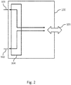
- FIG. 2 Such an operation is shown on Fig. 2 .
- relaying only takes place between the first port 101 and the local interface 103, as well as between the second port 102 and the local interface 103.
- packets or data are not relayed between the first port 101 and second port 102.
- All data received at the local interface 103 are preferably here output to both the first port 101 and the second port 102.
- the data or data packets are preferably duplicated, and an output takes place at both ports 101 and 102.
- the data received at the local interface 103 are preferably output both to the first port 101 and to the second port 102.
- Ports 101 and 102 are here used for connection with two independent networks of a network system (not shown on Fig. 2 ), and are designed accordingly.
- the data of the local interface 103 are hence output identically on both networks of the network system.
- Data received at the first port 101 and at the second port 102 are output to the local interface 103 or relayed to the latter.
- the switching device 104 is here preferably designed in such a way as to relay the data or data packets received at the first port 101 or the second port 102 to the local interface 103 if no copy of the data or data packet was received at the end system device 100 chronologically prior to receiving the data or data packet.
- the determination of a copy can here take place using a sequential number or user data of the received data or received data packet, for example.
- the switching device 104 can accordingly be set up to check whether data or a data packet with an identical sequential number or identical user data have already been received, and correspondingly implement the transfer or discard the received data or the received data packet if a copy of the data or data packet was received at the end system device 100 chronologically prior to receiving the data packet. Therefore, it is evident to the expert that not all data or data packets received at the first port 101 and the second port 102 must be relayed to the local interface.
- Such a first mode described above can be used when the end system device 100 is utilized in a network with a star topology.
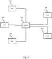
- Such a topology is exemplarily shown on Fig. 3 .
- One of the first 101 and second 102 ports of the end system 100 is here connected with a switch 103.
- the other port of the end system 101 or 102 is connected with a second network of the network system, which is not depicted on Fig. 3 for purposes of simplification, and also uses star topology in its structural design.
- the data output by the port connected with the switch 300 are output to the switch 300, which relays the data to another end system 100.
- the switching device 104 is designed to relay data or data packets received at the first port 101 to the second port 102 or to the local interface 103 or output them to the latter.
- data or data packets received at the second port 102 are relayed to the first port 101 or to the local interface 103 or output to the latter, and data or data packets received at the local interface 103 are relayed to the first port 101 and the second port 102.
- the switching device 104 is here preferably designed in such a way that data received at the first port 101 are relayed to the local interface 103 if the data or data packet are intended for the end system device 104. Otherwise, the switching device 104 is preferably designed to relay the data received at the first port 101 to the second port 102 if the data or data packet are not intended for the end system device 104 (but rather for another end system device, for example).
- data received at the second port 102 are preferably relayed to the local interface 103 if the data packet or data is/are intended for the end system device 100. Otherwise, data or data packets received at the second port 102 are relayed to the first port 101 if the data or data packet are not intended for the end system device 100. Such a determination can be made based on a packet header, for example.
- the switching device 104 can preferably also check whether a copy of the data or data packet was received at the end system device 100 chronologically prior to receiving the data or data packet, and can accordingly relay data or data packets received at the first port 101 to the local interface 103 if the data or data packet are intended for the end system device and no copy of the data or data packet was received at the end system device 100 chronologically prior to receiving the data or data packet.
- the determination of whether a copy was already received can be made according to the above explanations concerning the first mode.
- the data received at the local interface 103 are preferably output to both ports 101 and 102 according to the operation in the first mode. This can take place according to the above explanations concerning the first mode.
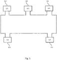
- Fig. 5 here depicts the use of an end system device 100 during operation in the second mode in a network system.
- the end systems 100 are arranged in a network with an annular topology, wherein the first and second ports of the end system device 100 are each connected with a port of another end system device 100.
- an end system device 100 receives data from the accompanying local interface, it outputs the latter to both ports.
- the data thus move in both directions in the annular network, i.e., clockwise and counterclockwise on Fig. 5 .
- the data packets are received by the respectively next end system device 100.
- the switching device of the respective end system device now determines whether the data are intended for it. If this is not the case, it outputs the data at its respective other port, and the data are disseminated further in the same direction in the annular network.
- the end system device 100 If the data are intended for the end system device 100, i.e., if the end system device is the destination end system device of the data or data packet, it relays the latter to its local interface. Since the data are disseminated over the network in two directions, the destination end system device at a later point in time again reaches the same data or the same data packet at the other port of the destination end system device. The latter is then preferably discarded by the switching device, as explained above.
- An end system device is here further preferably designed to check whether it has already relayed the data packet or a copy thereof. If this is the case, the switching device of the end system device is preferably designed to discard the data packet. Therefore, it is obvious to the expert that not all data or data packets received at the ports must be relayed to the respective other port.
- the embodiment of the end system device 100 with a switching device 104 described above makes it possible to operate the end system device 100 in both a first mode and in a second mode.
- the end system device 100 can thus be operated in annular or star topologies or networks with a single implementation of the end system.
- the same end system can be used in ring and star topologies, and the end system need only be developed and certified once, for example. For example, this reduces the system costs while also allowing a simpler reconfiguration.
- the switching device 100 described above can here integrating a switch or integrating a miniature switch into an end system or an end system device.
- the switch or miniature switch can here be deactivated to establish the first mode, and activated to establish the second mode, so as to achieve the relaying properties of the switching device 104.
- the switch is not active during operation in a first mode, and packets are not relayed between the first port 101 and the second port 102.
- the switch In the second mode, the switch is active, and relaying between the ports 101 and 102 does take place.
- the switching device can be designed to be switched or switch into the first mode or second mode, for example as a function of a resistance, a configuration parameter or dataset or an input signal.
- the switching device can check a resistance between two pins or two inputs (not shown on the figures), for example. If the resistance is high or low (high or low), a corresponding configuration can be implemented. For example, a configuration can thus take place by connecting the two inputs, e.g., by means of soldering or an adjustable jumper.
- a configuration dataset can also be used for configuration purposes.
- the latter can be stored in an external memory, e.g., an EEPROM.
- This configuration dataset can then be read out by the switching device, and a corresponding configuration can be implemented in the first mode or the second mode.
- Operation is preferably held constant in the first mode or the second mode during operation of the end system device after a start.
- the end system device is started by supplying power or using a switch, for example, the switching device is configured, and the mode cannot be subsequently changed during operation, i.e., until the end system device or switching device is turned off, for example.
- operation and correct relaying of data can be ensured after the network with the end system devices has been broken down, since one of the end system devices is prevented from switching over to another mode, which can lead to malfunctions in the network system.
- Such an end system device described above and an accompanying method can preferably be designed for communication between aircraft systems, in particular airplane systems.
- an end system device and an accompanying method can be designed to communicate in AFDX networks, at least in the case of configuration in the first mode.
- an end system device described above and an accompanying method can also be designed for use in an automobile (automobile end system) or in another vehicle (vehicle end system).
- vehicle end system vehicle end system
- This is advantageous in particular in vehicles where elevated requirements are placed on data transmission between end systems, such as sensors and control devices of a vehicle, owing to drive-by-wire, automated driving, etc.
- Autonomy along with driver assistance systems or Advanced Driver Assistance Systems (ADAS) are also to be mentioned here as keywords.
- ADAS Advanced Driver Assistance Systems
- the end system device is here preferably designed for deterministic network communication.
- end system devices or end systems are devices connected with a computer network that sit at the edge of the network. These end systems provide information and services.
- end systems are devices whose applications access the network components, so as to transmit or receive data from the network, such as sensors, control devices, etc.
- the end systems can be designed as AFDX end systems, which are part of an avionics or aircraft subsystem, which have to send data over the AFDX network, for example.
- a subsystem for example an avionics or aircraft subsystem, comprises an end system or an end system device as described above, which here is preferably designed as an AFDX end system device.
- a corresponding method for an end system device here comprises the steps of switching a switching device of the end system device into a first or second mode.
- the method comprises the step of relaying data received at a first and a second port of the end system device to a local interface of the end system device, and relaying data received at the interface to the first port and the second port.
- the method further comprises the step of relaying data received at the first port to the second port or to the interface, relaying the data received at the second port to the first port or to the interface, and relaying data received at the interface to the first port and the second port.
- the term "relay” is to be construed to mean that the data or at least the user data of a data packet are received at one point and output at another point.
- An adjustment of the data packet can here be provided, for example a change in the header or the like.
- a second switching device can be provided, which is set up identically with the switching device described above. All above statements thus apply accordingly to a second switching device.
- the second switching device is here used for integration into the described second network of the network system.
Landscapes
- Engineering & Computer Science (AREA)
- Signal Processing (AREA)
- Computer Networks & Wireless Communication (AREA)
- Physics & Mathematics (AREA)
- Astronomy & Astrophysics (AREA)
- Aviation & Aerospace Engineering (AREA)
- General Physics & Mathematics (AREA)
- Health & Medical Sciences (AREA)
- Computing Systems (AREA)
- General Health & Medical Sciences (AREA)
- Medical Informatics (AREA)
- Small-Scale Networks (AREA)
Abstract
Description
- The present invention relates to the technical area of networks for communication between end systems, and in particular to an end system device with an integrated switching device for such a network.
- For example, Avionics Full Duplex Switching Ethernet (AFDX) is used for communication between aircraft systems, which is a conventional designation for ARINC Standard 664. This standard describes a network and the accompanying protocol for communication between aircraft systems.
- In such AFDX networks, AFDX end systems are connected in a star topology by means of switches in point-to-multipoint connections (P2MP). To ensure redundancy, the network is duplicated. The network system thus encompasses a first network and a second network, which are built independently of each other. The data of the network end system are here output via two ports of the network end system to the independent networks.
- In addition, the protocols High Availability Seamless Redundancy (HRS) and Parallel Redundancy Protocol (PRP) are used to ensure redundancy, in particular in networks of industrial and power plant automation. The latter are described in the IEC 62439-3 standard.
- It may be desirable to provide an improved end system device for a network system for communication between end systems.
- Accordingly, an end system device, a network system, a vehicle as well as a corresponding method can be provided according to one aspect of the present invention.
- The subject matter of the invention is indicated by the features of the subject matter of the independent claims. Exemplary embodiments and other aspects of the invention are indicated by the subject matter of the independent claims and of the following description.
- In one aspect, an end system device for a network system comprises a first port for connection with the network system, a second port for connection with the network system, a local interface and a switching device. The switching device is here designed for switching into a first or a second mode. In the first mode, the switching device is set up to relay data received at the first and second port to the local interface, and relay data received at the interface to the first port and the second port.
- In the second mode, the switching device is set up to relay data received at the first port to the second port or to the local interface, relay data received at the second port to the first port or to the interface, and relay data received at the interface to the first port and the second port.
- In one aspect, a network system for communication between the end systems encompasses at least one, in particular at least two, end system device(s) according to an aspect of the present invention.
- In one aspect, a vehicle, in particular an airplane, encompasses at least one, in particular two, end system device(s) according to an aspect of the present invention.
- In one aspect, a method for an end system device for a network system encompasses the steps of switching a switching device of the end system device into a first or a second mode, in the first mode, relaying data received at a first and second port of the end system device to a local interface of the end system device and relaying data received at the interface to the first port and second port, as well as, in the second mode, relaying data received at the first port to the second port or to the interface, relaying data received at the second port to the first port or to the interface and relaying data received at the interface to the first port and the second port.
- Additional exemplary embodiments of the present invention will be described below, drawing reference to the figures.
-
Fig. 1 shows a schematic view of an embodiment of the end system device. -
Fig. 2 shows an operation of the end system device in a first mode. -
Fig. 3 shows a network system during an operation of the end system device in the first mode. -
Fig. 4 shows an operation of the end system device in a second mode. -
Fig. 5 shows a network system during an operation of the end system device in the second mode. - The illustrations on the figures are schematic and not to scale. In the following description of
Fig. 1 to 11 , the same reference number is used for identical or corresponding elements. -
Fig. 1 shows a schematic view of anend system device 100. Theend system device 100 here encompasses afirst port 101 and asecond port 102. These ports are used for connection with the network system, and thus constitute network ports. Theend system device 100 further encompasses alocal interface 103. Thislocal interface 103 is used for connection with local components of the end system, and thus for local communication. For example, thislocal interface 103 can be designed as a CPU interface or host CPU interface. In contrast to theports local interface 103 is used for local combination with local components, and not for combination with a network system. In addition, theend system device 100 encompasses aswitching device 104. Thisswitching device 104 is used to distribute or relay data received at thefirst port 101, thesecond port 102 and thelocal interface 103, for example data packets. The precise function will be described below. - The
switching device 104 can here be switched into a first and a second mode, or is designed to switch into a first or a second mode. - In the first mode, the data received at the first 101 and second 102 port are relayed to the
local interface 103. Data received at thelocal interface 103 are in turn relayed to thefirst port 101 and thesecond port 102. - Such an operation is shown on
Fig. 2 . As evident fromFig. 2 , relaying only takes place between thefirst port 101 and thelocal interface 103, as well as between thesecond port 102 and thelocal interface 103. However, packets or data are not relayed between thefirst port 101 andsecond port 102. - All data received at the
local interface 103 are preferably here output to both thefirst port 101 and thesecond port 102. As a consequence, the data or data packets are preferably duplicated, and an output takes place at bothports - Therefore, the data received at the
local interface 103 are preferably output both to thefirst port 101 and to thesecond port 102.Ports Fig. 2 ), and are designed accordingly. The data of thelocal interface 103 are hence output identically on both networks of the network system. - Data received at the
first port 101 and at thesecond port 102 are output to thelocal interface 103 or relayed to the latter. Theswitching device 104 is here preferably designed in such a way as to relay the data or data packets received at thefirst port 101 or thesecond port 102 to thelocal interface 103 if no copy of the data or data packet was received at theend system device 100 chronologically prior to receiving the data or data packet. The determination of a copy can here take place using a sequential number or user data of the received data or received data packet, for example. For example, theswitching device 104 can accordingly be set up to check whether data or a data packet with an identical sequential number or identical user data have already been received, and correspondingly implement the transfer or discard the received data or the received data packet if a copy of the data or data packet was received at theend system device 100 chronologically prior to receiving the data packet. Therefore, it is evident to the expert that not all data or data packets received at thefirst port 101 and thesecond port 102 must be relayed to the local interface. - Such a first mode described above can be used when the
end system device 100 is utilized in a network with a star topology. - Such a topology is exemplarily shown on
Fig. 3 . One of the first 101 and second 102 ports of theend system 100 is here connected with aswitch 103. The other port of theend system Fig. 3 for purposes of simplification, and also uses star topology in its structural design. The data output by the port connected with theswitch 300 are output to theswitch 300, which relays the data to anotherend system 100. -
Fig. 4 will now be discussed in order to describe the second mode. In the second mode, theswitching device 104 is designed to relay data or data packets received at thefirst port 101 to thesecond port 102 or to thelocal interface 103 or output them to the latter. - In addition, data or data packets received at the
second port 102 are relayed to thefirst port 101 or to thelocal interface 103 or output to the latter, and data or data packets received at thelocal interface 103 are relayed to thefirst port 101 and thesecond port 102. - In contrast to operation in the first mode, it must correspondingly be noted that data or data packets are also relayed between the first and
second ports - The
switching device 104 is here preferably designed in such a way that data received at thefirst port 101 are relayed to thelocal interface 103 if the data or data packet are intended for theend system device 104. Otherwise, theswitching device 104 is preferably designed to relay the data received at thefirst port 101 to thesecond port 102 if the data or data packet are not intended for the end system device 104 (but rather for another end system device, for example). - Accordingly, data received at the
second port 102 are preferably relayed to thelocal interface 103 if the data packet or data is/are intended for theend system device 100. Otherwise, data or data packets received at thesecond port 102 are relayed to thefirst port 101 if the data or data packet are not intended for theend system device 100. Such a determination can be made based on a packet header, for example. - Furthermore, the
switching device 104 can preferably also check whether a copy of the data or data packet was received at theend system device 100 chronologically prior to receiving the data or data packet, and can accordingly relay data or data packets received at thefirst port 101 to thelocal interface 103 if the data or data packet are intended for the end system device and no copy of the data or data packet was received at theend system device 100 chronologically prior to receiving the data or data packet. The same holds true correspondingly for the data or data packets received at the second port. The determination of whether a copy was already received can be made according to the above explanations concerning the first mode. - The data received at the
local interface 103 are preferably output to bothports -
Fig. 5 here depicts the use of anend system device 100 during operation in the second mode in a network system. - As evident from
Fig. 5 , theend systems 100 are arranged in a network with an annular topology, wherein the first and second ports of theend system device 100 are each connected with a port of anotherend system device 100. - The operation of such an annular network system will now be exemplarily described based on
Fig. 5 . If anend system device 100 receives data from the accompanying local interface, it outputs the latter to both ports. The data thus move in both directions in the annular network, i.e., clockwise and counterclockwise onFig. 5 . The data packets are received by the respectively nextend system device 100. The switching device of the respective end system device now determines whether the data are intended for it. If this is not the case, it outputs the data at its respective other port, and the data are disseminated further in the same direction in the annular network. If the data are intended for theend system device 100, i.e., if the end system device is the destination end system device of the data or data packet, it relays the latter to its local interface. Since the data are disseminated over the network in two directions, the destination end system device at a later point in time again reaches the same data or the same data packet at the other port of the destination end system device. The latter is then preferably discarded by the switching device, as explained above. An end system device is here further preferably designed to check whether it has already relayed the data packet or a copy thereof. If this is the case, the switching device of the end system device is preferably designed to discard the data packet. Therefore, it is obvious to the expert that not all data or data packets received at the ports must be relayed to the respective other port. - Therefore, the embodiment of the
end system device 100 with aswitching device 104 described above makes it possible to operate theend system device 100 in both a first mode and in a second mode. Theend system device 100 can thus be operated in annular or star topologies or networks with a single implementation of the end system. As a result, the same end system can be used in ring and star topologies, and the end system need only be developed and certified once, for example. For example, this reduces the system costs while also allowing a simpler reconfiguration. - For example, the
switching device 100 described above can here integrating a switch or integrating a miniature switch into an end system or an end system device. The switch or miniature switch can here be deactivated to establish the first mode, and activated to establish the second mode, so as to achieve the relaying properties of theswitching device 104. As a consequence, the switch is not active during operation in a first mode, and packets are not relayed between thefirst port 101 and thesecond port 102. In the second mode, the switch is active, and relaying between theports - Options and additional comments relating to configuration or setting or adjusting the switching device to the first mode or the second mode will be described below.
- The switching device can be designed to be switched or switch into the first mode or second mode, for example as a function of a resistance, a configuration parameter or dataset or an input signal.
- Given a configuration based on an external resistance, the switching device can check a resistance between two pins or two inputs (not shown on the figures), for example. If the resistance is high or low (high or low), a corresponding configuration can be implemented. For example, a configuration can thus take place by connecting the two inputs, e.g., by means of soldering or an adjustable jumper.
- In addition, a configuration dataset can also be used for configuration purposes. For example, the latter can be stored in an external memory, e.g., an EEPROM. This configuration dataset can then be read out by the switching device, and a corresponding configuration can be implemented in the first mode or the second mode.
- Further conceivable is configuration by means of a parameter, which is provided to the switching device at the start.
- Operation is preferably held constant in the first mode or the second mode during operation of the end system device after a start. Expressed differently, the end system device is started by supplying power or using a switch, for example, the switching device is configured, and the mode cannot be subsequently changed during operation, i.e., until the end system device or switching device is turned off, for example. As a result, operation and correct relaying of data can be ensured after the network with the end system devices has been broken down, since one of the end system devices is prevented from switching over to another mode, which can lead to malfunctions in the network system.
- Such an end system device described above and an accompanying method can preferably be designed for communication between aircraft systems, in particular airplane systems. In particular, an end system device and an accompanying method can be designed to communicate in AFDX networks, at least in the case of configuration in the first mode.
- However, such an end system device described above and an accompanying method can also be designed for use in an automobile (automobile end system) or in another vehicle (vehicle end system). This is advantageous in particular in vehicles where elevated requirements are placed on data transmission between end systems, such as sensors and control devices of a vehicle, owing to drive-by-wire, automated driving, etc. Autonomy along with driver assistance systems or Advanced Driver Assistance Systems (ADAS) are also to be mentioned here as keywords. Also provided are configurations for use in ships, industrial plants, etc.
- The end system device is here preferably designed for deterministic network communication.
- As known to the expert, end system devices or end systems are devices connected with a computer network that sit at the edge of the network. These end systems provide information and services. Expressed differently, end systems are devices whose applications access the network components, so as to transmit or receive data from the network, such as sensors, control devices, etc. In the case of AFDX, the end systems can be designed as AFDX end systems, which are part of an avionics or aircraft subsystem, which have to send data over the AFDX network, for example. Expressed differently, a subsystem, for example an avionics or aircraft subsystem, comprises an end system or an end system device as described above, which here is preferably designed as an AFDX end system device.
- A corresponding method for an end system device here comprises the steps of switching a switching device of the end system device into a first or second mode. In the second mode, the method comprises the step of relaying data received at a first and a second port of the end system device to a local interface of the end system device, and relaying data received at the interface to the first port and the second port. In the second mode, the method further comprises the step of relaying data received at the first port to the second port or to the interface, relaying the data received at the second port to the first port or to the interface, and relaying data received at the interface to the first port and the second port.
- Let it here be noted that the term "relay" is to be construed to mean that the data or at least the user data of a data packet are received at one point and output at another point. An adjustment of the data packet can here be provided, for example a change in the header or the like.
- In another exemplary embodiment not shown on the figures, a second switching device can be provided, which is set up identically with the switching device described above. All above statements thus apply accordingly to a second switching device. The second switching device is here used for integration into the described second network of the network system.
- In addition, let it be noted that "comprising" and "having" do not rule out other elements or steps, and that "a" or "an" do not preclude a plurality. Let it further be noted that features or steps described with reference to one of the above exemplary embodiments can also be used in combination with other features or steps of other exemplary embodiments described above. Reference numbers in the claims are not to be regarded as a limitation.
Claims (10)
- An end system device (100) for a network system, wherein the end system device comprises:- a first port (101) for connection with the network system;- a second port (102) for connection with the network system;- a local interface (103);- a switching device (104);wherein the switching device (104) is designed for switching into a first or a second mode; and
wherein:- in the first mode, the switching device (104) is set up to relay data received at the first (101) and second (102) port to the local interface (103), and relay data received at the local interface (103) to the first port (101) and the second port (102); and- in the second mode, the switching device (104) is set up to relay data received at the first port (101) to the second port (102) or to the local interface (103), relay data received at the second port (102) to the first port (101) or to the local interface (103), and relay data received at the local interface (103) to the first port (101) and the second port (102). - The end system device (100) of one of the preceding claims, wherein the switching device (104), in a first mode, is designed to relay data from the first port (101) or second port (102) to the local interface (103) if no copy of the data was received at the end system device (100) chronologically prior to receiving the data, and
Discard data from the first port (101) or second port (102) if a copy of the data was received at the end system device (100) chronologically prior to receiving the data. - The end system device (100) of one of the preceding claims, wherein the switching device (104) is designed, in the second mode, to- relay data received at the first port (101) to the local interface (103) if the data are intended for the end system device (100), and no copy of the data was received at the end system device (100) chronologically prior to receiving the data,- relay data received at the first port (101) to the second port (102) if the data are not intended for the end system device (100),- relay data received at the second port (102) to the local interface (103) if the data are intended for the end system device (100), and no copy of the data was received at the end system device (100) chronologically prior to receiving the data,- relay data received at the second port (102) to the first port (101) if the data are not intended for the end system device (100).
- The end system device (100) of one of the preceding claims, wherein the switching device (104) is designed to switch between the first mode and the second mode, as a function of:- a resistance;- an input signal; and/or- a configuration parameter.
- The end system device (100) of one of the preceding claims, wherein the switching device (104) is designed to switch into the first mode or the second mode when the end system device (100) starts operating, and keep the latter constant during operation of the end system device (100).
- The end system device (100) of one of the preceding claims, wherein the end system device (100) is designed for communication with an ADFX network.
- The end system device (100) of one of the preceding claims, wherein the end system device (100) is designed for communication between vehicle end systems, in particular aircraft end systems.
- A network system for communication between end systems, which comprises at least one end system device (100) of one of the preceding claims.
- A vehicle, in particular an aircraft, which comprises at least one end system device (100) of one of claims 1 to 7.
- A method for an end system device (100) for a network system, wherein the method encompasses the following steps:switching a switching device (104) of the end system device (100) into a first or second mode;in the first mode, relaying data received at a first (101) and a second (102) port of the end system device (100) to a local interface (103) of the end system device (100) and relaying data received at the local interface (103) to the first port (101) and the second port (102); andin the second mode, relaying data received at the first port (101) to the second port (102) or to the local interface (103), relaying data received at the second port (102) to the first port (101) or to the local interface (103), and relaying data received at the local interface (103) to the first port (101) and the second port (102).
Applications Claiming Priority (1)
| Application Number | Priority Date | Filing Date | Title |
|---|---|---|---|
| DE102016110148.6A DE102016110148A1 (en) | 2016-06-01 | 2016-06-01 | End system device with integrated switching device |
Publications (2)
| Publication Number | Publication Date |
|---|---|
| EP3253016A1 true EP3253016A1 (en) | 2017-12-06 |
| EP3253016B1 EP3253016B1 (en) | 2019-08-21 |
Family
ID=59093354
Family Applications (1)
| Application Number | Title | Priority Date | Filing Date |
|---|---|---|---|
| EP17173876.8A Active EP3253016B1 (en) | 2016-06-01 | 2017-06-01 | End system device with integrated switching device |
Country Status (3)
| Country | Link |
|---|---|
| US (1) | US10419104B2 (en) |
| EP (1) | EP3253016B1 (en) |
| DE (1) | DE102016110148A1 (en) |
Families Citing this family (1)
| Publication number | Priority date | Publication date | Assignee | Title |
|---|---|---|---|---|
| DE102017130386A1 (en) * | 2017-12-18 | 2019-06-19 | Northrop Grumman Litef Gmbh | Vehicle with fail-safe internal data transmission |
Citations (3)
| Publication number | Priority date | Publication date | Assignee | Title |
|---|---|---|---|---|
| US20060110162A1 (en) * | 2004-11-22 | 2006-05-25 | Fujitsu Network Communications, Inc. | Optical ring network for extended broadcasting |
| US20110116508A1 (en) * | 2008-07-22 | 2011-05-19 | Abb Research Ltd | Ring coupling nodes for high availability networks |
| EP2566111A1 (en) * | 2011-08-30 | 2013-03-06 | ABB Technology AG | Utility communication method and system |
Family Cites Families (3)
| Publication number | Priority date | Publication date | Assignee | Title |
|---|---|---|---|---|
| US8953438B2 (en) * | 2010-07-30 | 2015-02-10 | Honeywell International Inc. | Multiple source virtual link reversion in safety critical switched networks |
| US20130208630A1 (en) * | 2012-02-15 | 2013-08-15 | Ge Aviation Systems Llc | Avionics full-duplex switched ethernet network |
| GB2532773A (en) * | 2014-11-27 | 2016-06-01 | Airbus Operations Sas | Improvements in or relating to avionics networks |
-
2016
- 2016-06-01 DE DE102016110148.6A patent/DE102016110148A1/en not_active Ceased
-
2017
- 2017-06-01 US US15/611,094 patent/US10419104B2/en active Active
- 2017-06-01 EP EP17173876.8A patent/EP3253016B1/en active Active
Patent Citations (3)
| Publication number | Priority date | Publication date | Assignee | Title |
|---|---|---|---|---|
| US20060110162A1 (en) * | 2004-11-22 | 2006-05-25 | Fujitsu Network Communications, Inc. | Optical ring network for extended broadcasting |
| US20110116508A1 (en) * | 2008-07-22 | 2011-05-19 | Abb Research Ltd | Ring coupling nodes for high availability networks |
| EP2566111A1 (en) * | 2011-08-30 | 2013-03-06 | ABB Technology AG | Utility communication method and system |
Also Published As
| Publication number | Publication date |
|---|---|
| US20170353230A1 (en) | 2017-12-07 |
| EP3253016B1 (en) | 2019-08-21 |
| US10419104B2 (en) | 2019-09-17 |
| DE102016110148A1 (en) | 2017-12-07 |
Similar Documents
| Publication | Publication Date | Title |
|---|---|---|
| EP3119063B1 (en) | System and method for a flexible deterministic communications network | |
| CN108023872B (en) | Vehicle-mounted network system | |
| JP6436242B2 (en) | Industrial equipment communication system, communication method, and industrial equipment | |
| US9619252B2 (en) | Reconfigurable avionics equipment and method of reconfiguring such equipment | |
| US7505400B2 (en) | Dual lane connection to dual redundant avionics networks | |
| US11362859B2 (en) | In-vehicle communication device and in-vehicle system | |
| Fuchs et al. | The evolution of avionics networks from ARINC 429 to AFDX | |
| US8953438B2 (en) | Multiple source virtual link reversion in safety critical switched networks | |
| US20120290692A1 (en) | Static Ring Network for Vehicle Communications | |
| US9369341B2 (en) | Static ring network for vehicle communications | |
| BRPI1010429A2 (en) | airplane communication system | |
| EP1841152A1 (en) | System and method for redundant switched communications | |
| CN106059874A (en) | Automation device for redundant control of bus subscriber | |
| EP1995148A1 (en) | Transmission system for rail vehicles using two redundant bus systems | |
| EP3253016B1 (en) | End system device with integrated switching device | |
| US20170192920A1 (en) | Transmission unit with checking function | |
| US20150163844A1 (en) | Communication system in an aircraft comprising a redundant network | |
| WO2014087434A1 (en) | Improved avionic ethernet network and method of transmitting blocks of data in the network | |
| JP2017011566A (en) | Relay device | |
| US7706931B2 (en) | Control system | |
| US10277419B2 (en) | Hybrid network end system device | |
| CN110214435A (en) | Communication network | |
| CN114846777B (en) | Network equipment used to provide redundancy in industrial networks | |
| WO2005114434A1 (en) | Vehicle network with interrupted shared access bus | |
| Parkes et al. | SpaceWire: Spacecraft onboard data-handling network |
Legal Events
| Date | Code | Title | Description |
|---|---|---|---|
| PUAI | Public reference made under article 153(3) epc to a published international application that has entered the european phase |
Free format text: ORIGINAL CODE: 0009012 |
|
| STAA | Information on the status of an ep patent application or granted ep patent |
Free format text: STATUS: THE APPLICATION HAS BEEN PUBLISHED |
|
| AK | Designated contracting states |
Kind code of ref document: A1 Designated state(s): AL AT BE BG CH CY CZ DE DK EE ES FI FR GB GR HR HU IE IS IT LI LT LU LV MC MK MT NL NO PL PT RO RS SE SI SK SM TR |
|
| AX | Request for extension of the european patent |
Extension state: BA ME |
|
| STAA | Information on the status of an ep patent application or granted ep patent |
Free format text: STATUS: REQUEST FOR EXAMINATION WAS MADE |
|
| 17P | Request for examination filed |
Effective date: 20180312 |
|
| RBV | Designated contracting states (corrected) |
Designated state(s): AL AT BE BG CH CY CZ DE DK EE ES FI FR GB GR HR HU IE IS IT LI LT LU LV MC MK MT NL NO PL PT RO RS SE SI SK SM TR |
|
| STAA | Information on the status of an ep patent application or granted ep patent |
Free format text: STATUS: EXAMINATION IS IN PROGRESS |
|
| 17Q | First examination report despatched |
Effective date: 20180817 |
|
| REG | Reference to a national code |
Ref country code: DE Ref legal event code: R079 Ref document number: 602017006264 Country of ref document: DE Free format text: PREVIOUS MAIN CLASS: H04L0012931000 Ipc: H04B0007185000 |
|
| GRAP | Despatch of communication of intention to grant a patent |
Free format text: ORIGINAL CODE: EPIDOSNIGR1 |
|
| STAA | Information on the status of an ep patent application or granted ep patent |
Free format text: STATUS: GRANT OF PATENT IS INTENDED |
|
| RIC1 | Information provided on ipc code assigned before grant |
Ipc: H04L 5/14 20060101ALI20190402BHEP Ipc: H04L 29/08 20060101ALI20190402BHEP Ipc: H04B 7/185 20060101AFI20190402BHEP |
|
| INTG | Intention to grant announced |
Effective date: 20190418 |
|
| GRAS | Grant fee paid |
Free format text: ORIGINAL CODE: EPIDOSNIGR3 |
|
| GRAA | (expected) grant |
Free format text: ORIGINAL CODE: 0009210 |
|
| STAA | Information on the status of an ep patent application or granted ep patent |
Free format text: STATUS: THE PATENT HAS BEEN GRANTED |
|
| AK | Designated contracting states |
Kind code of ref document: B1 Designated state(s): AL AT BE BG CH CY CZ DE DK EE ES FI FR GB GR HR HU IE IS IT LI LT LU LV MC MK MT NL NO PL PT RO RS SE SI SK SM TR |
|
| REG | Reference to a national code |
Ref country code: GB Ref legal event code: FG4D |
|
| REG | Reference to a national code |
Ref country code: CH Ref legal event code: EP |
|
| REG | Reference to a national code |
Ref country code: DE Ref legal event code: R096 Ref document number: 602017006264 Country of ref document: DE |
|
| REG | Reference to a national code |
Ref country code: AT Ref legal event code: REF Ref document number: 1170925 Country of ref document: AT Kind code of ref document: T Effective date: 20190915 |
|
| REG | Reference to a national code |
Ref country code: IE Ref legal event code: FG4D |
|
| REG | Reference to a national code |
Ref country code: LT Ref legal event code: MG4D |
|
| REG | Reference to a national code |
Ref country code: NL Ref legal event code: MP Effective date: 20190821 |
|
| PG25 | Lapsed in a contracting state [announced via postgrant information from national office to epo] |
Ref country code: PT Free format text: LAPSE BECAUSE OF FAILURE TO SUBMIT A TRANSLATION OF THE DESCRIPTION OR TO PAY THE FEE WITHIN THE PRESCRIBED TIME-LIMIT Effective date: 20191223 Ref country code: NO Free format text: LAPSE BECAUSE OF FAILURE TO SUBMIT A TRANSLATION OF THE DESCRIPTION OR TO PAY THE FEE WITHIN THE PRESCRIBED TIME-LIMIT Effective date: 20191121 Ref country code: HR Free format text: LAPSE BECAUSE OF FAILURE TO SUBMIT A TRANSLATION OF THE DESCRIPTION OR TO PAY THE FEE WITHIN THE PRESCRIBED TIME-LIMIT Effective date: 20190821 Ref country code: SE Free format text: LAPSE BECAUSE OF FAILURE TO SUBMIT A TRANSLATION OF THE DESCRIPTION OR TO PAY THE FEE WITHIN THE PRESCRIBED TIME-LIMIT Effective date: 20190821 Ref country code: FI Free format text: LAPSE BECAUSE OF FAILURE TO SUBMIT A TRANSLATION OF THE DESCRIPTION OR TO PAY THE FEE WITHIN THE PRESCRIBED TIME-LIMIT Effective date: 20190821 Ref country code: LT Free format text: LAPSE BECAUSE OF FAILURE TO SUBMIT A TRANSLATION OF THE DESCRIPTION OR TO PAY THE FEE WITHIN THE PRESCRIBED TIME-LIMIT Effective date: 20190821 Ref country code: NL Free format text: LAPSE BECAUSE OF FAILURE TO SUBMIT A TRANSLATION OF THE DESCRIPTION OR TO PAY THE FEE WITHIN THE PRESCRIBED TIME-LIMIT Effective date: 20190821 Ref country code: BG Free format text: LAPSE BECAUSE OF FAILURE TO SUBMIT A TRANSLATION OF THE DESCRIPTION OR TO PAY THE FEE WITHIN THE PRESCRIBED TIME-LIMIT Effective date: 20191121 |
|
| PG25 | Lapsed in a contracting state [announced via postgrant information from national office to epo] |
Ref country code: AL Free format text: LAPSE BECAUSE OF FAILURE TO SUBMIT A TRANSLATION OF THE DESCRIPTION OR TO PAY THE FEE WITHIN THE PRESCRIBED TIME-LIMIT Effective date: 20190821 Ref country code: ES Free format text: LAPSE BECAUSE OF FAILURE TO SUBMIT A TRANSLATION OF THE DESCRIPTION OR TO PAY THE FEE WITHIN THE PRESCRIBED TIME-LIMIT Effective date: 20190821 Ref country code: LV Free format text: LAPSE BECAUSE OF FAILURE TO SUBMIT A TRANSLATION OF THE DESCRIPTION OR TO PAY THE FEE WITHIN THE PRESCRIBED TIME-LIMIT Effective date: 20190821 Ref country code: RS Free format text: LAPSE BECAUSE OF FAILURE TO SUBMIT A TRANSLATION OF THE DESCRIPTION OR TO PAY THE FEE WITHIN THE PRESCRIBED TIME-LIMIT Effective date: 20190821 Ref country code: GR Free format text: LAPSE BECAUSE OF FAILURE TO SUBMIT A TRANSLATION OF THE DESCRIPTION OR TO PAY THE FEE WITHIN THE PRESCRIBED TIME-LIMIT Effective date: 20191122 Ref country code: IS Free format text: LAPSE BECAUSE OF FAILURE TO SUBMIT A TRANSLATION OF THE DESCRIPTION OR TO PAY THE FEE WITHIN THE PRESCRIBED TIME-LIMIT Effective date: 20191221 |
|
| REG | Reference to a national code |
Ref country code: AT Ref legal event code: MK05 Ref document number: 1170925 Country of ref document: AT Kind code of ref document: T Effective date: 20190821 |
|
| PG25 | Lapsed in a contracting state [announced via postgrant information from national office to epo] |
Ref country code: TR Free format text: LAPSE BECAUSE OF FAILURE TO SUBMIT A TRANSLATION OF THE DESCRIPTION OR TO PAY THE FEE WITHIN THE PRESCRIBED TIME-LIMIT Effective date: 20190821 |
|
| PG25 | Lapsed in a contracting state [announced via postgrant information from national office to epo] |
Ref country code: RO Free format text: LAPSE BECAUSE OF FAILURE TO SUBMIT A TRANSLATION OF THE DESCRIPTION OR TO PAY THE FEE WITHIN THE PRESCRIBED TIME-LIMIT Effective date: 20190821 Ref country code: EE Free format text: LAPSE BECAUSE OF FAILURE TO SUBMIT A TRANSLATION OF THE DESCRIPTION OR TO PAY THE FEE WITHIN THE PRESCRIBED TIME-LIMIT Effective date: 20190821 Ref country code: PL Free format text: LAPSE BECAUSE OF FAILURE TO SUBMIT A TRANSLATION OF THE DESCRIPTION OR TO PAY THE FEE WITHIN THE PRESCRIBED TIME-LIMIT Effective date: 20190821 Ref country code: AT Free format text: LAPSE BECAUSE OF FAILURE TO SUBMIT A TRANSLATION OF THE DESCRIPTION OR TO PAY THE FEE WITHIN THE PRESCRIBED TIME-LIMIT Effective date: 20190821 Ref country code: IT Free format text: LAPSE BECAUSE OF FAILURE TO SUBMIT A TRANSLATION OF THE DESCRIPTION OR TO PAY THE FEE WITHIN THE PRESCRIBED TIME-LIMIT Effective date: 20190821 Ref country code: DK Free format text: LAPSE BECAUSE OF FAILURE TO SUBMIT A TRANSLATION OF THE DESCRIPTION OR TO PAY THE FEE WITHIN THE PRESCRIBED TIME-LIMIT Effective date: 20190821 |
|
| PG25 | Lapsed in a contracting state [announced via postgrant information from national office to epo] |
Ref country code: IS Free format text: LAPSE BECAUSE OF FAILURE TO SUBMIT A TRANSLATION OF THE DESCRIPTION OR TO PAY THE FEE WITHIN THE PRESCRIBED TIME-LIMIT Effective date: 20200224 Ref country code: SM Free format text: LAPSE BECAUSE OF FAILURE TO SUBMIT A TRANSLATION OF THE DESCRIPTION OR TO PAY THE FEE WITHIN THE PRESCRIBED TIME-LIMIT Effective date: 20190821 Ref country code: SK Free format text: LAPSE BECAUSE OF FAILURE TO SUBMIT A TRANSLATION OF THE DESCRIPTION OR TO PAY THE FEE WITHIN THE PRESCRIBED TIME-LIMIT Effective date: 20190821 Ref country code: CZ Free format text: LAPSE BECAUSE OF FAILURE TO SUBMIT A TRANSLATION OF THE DESCRIPTION OR TO PAY THE FEE WITHIN THE PRESCRIBED TIME-LIMIT Effective date: 20190821 |
|
| REG | Reference to a national code |
Ref country code: DE Ref legal event code: R097 Ref document number: 602017006264 Country of ref document: DE |
|
| PLBE | No opposition filed within time limit |
Free format text: ORIGINAL CODE: 0009261 |
|
| STAA | Information on the status of an ep patent application or granted ep patent |
Free format text: STATUS: NO OPPOSITION FILED WITHIN TIME LIMIT |
|
| PG2D | Information on lapse in contracting state deleted |
Ref country code: IS |
|
| 26N | No opposition filed |
Effective date: 20200603 |
|
| PG25 | Lapsed in a contracting state [announced via postgrant information from national office to epo] |
Ref country code: SI Free format text: LAPSE BECAUSE OF FAILURE TO SUBMIT A TRANSLATION OF THE DESCRIPTION OR TO PAY THE FEE WITHIN THE PRESCRIBED TIME-LIMIT Effective date: 20190821 |
|
| PG25 | Lapsed in a contracting state [announced via postgrant information from national office to epo] |
Ref country code: MC Free format text: LAPSE BECAUSE OF FAILURE TO SUBMIT A TRANSLATION OF THE DESCRIPTION OR TO PAY THE FEE WITHIN THE PRESCRIBED TIME-LIMIT Effective date: 20190821 |
|
| REG | Reference to a national code |
Ref country code: CH Ref legal event code: PL |
|
| PG25 | Lapsed in a contracting state [announced via postgrant information from national office to epo] |
Ref country code: LU Free format text: LAPSE BECAUSE OF NON-PAYMENT OF DUE FEES Effective date: 20200601 |
|
| REG | Reference to a national code |
Ref country code: BE Ref legal event code: MM Effective date: 20200630 |
|
| PG25 | Lapsed in a contracting state [announced via postgrant information from national office to epo] |
Ref country code: IE Free format text: LAPSE BECAUSE OF NON-PAYMENT OF DUE FEES Effective date: 20200601 Ref country code: LI Free format text: LAPSE BECAUSE OF NON-PAYMENT OF DUE FEES Effective date: 20200630 Ref country code: CH Free format text: LAPSE BECAUSE OF NON-PAYMENT OF DUE FEES Effective date: 20200630 |
|
| PG25 | Lapsed in a contracting state [announced via postgrant information from national office to epo] |
Ref country code: BE Free format text: LAPSE BECAUSE OF NON-PAYMENT OF DUE FEES Effective date: 20200630 |
|
| PG25 | Lapsed in a contracting state [announced via postgrant information from national office to epo] |
Ref country code: MT Free format text: LAPSE BECAUSE OF FAILURE TO SUBMIT A TRANSLATION OF THE DESCRIPTION OR TO PAY THE FEE WITHIN THE PRESCRIBED TIME-LIMIT Effective date: 20190821 Ref country code: CY Free format text: LAPSE BECAUSE OF FAILURE TO SUBMIT A TRANSLATION OF THE DESCRIPTION OR TO PAY THE FEE WITHIN THE PRESCRIBED TIME-LIMIT Effective date: 20190821 |
|
| PG25 | Lapsed in a contracting state [announced via postgrant information from national office to epo] |
Ref country code: MK Free format text: LAPSE BECAUSE OF FAILURE TO SUBMIT A TRANSLATION OF THE DESCRIPTION OR TO PAY THE FEE WITHIN THE PRESCRIBED TIME-LIMIT Effective date: 20190821 |
|
| PGFP | Annual fee paid to national office [announced via postgrant information from national office to epo] |
Ref country code: DE Payment date: 20250618 Year of fee payment: 9 |
|
| PGFP | Annual fee paid to national office [announced via postgrant information from national office to epo] |
Ref country code: GB Payment date: 20250618 Year of fee payment: 9 |
|
| PGFP | Annual fee paid to national office [announced via postgrant information from national office to epo] |
Ref country code: FR Payment date: 20250625 Year of fee payment: 9 |