EP3252914B1 - Apparatus and method for sensing opening of current interrupt device of battery unit - Google Patents
Apparatus and method for sensing opening of current interrupt device of battery unit Download PDFInfo
- Publication number
- EP3252914B1 EP3252914B1 EP16743717.7A EP16743717A EP3252914B1 EP 3252914 B1 EP3252914 B1 EP 3252914B1 EP 16743717 A EP16743717 A EP 16743717A EP 3252914 B1 EP3252914 B1 EP 3252914B1
- Authority
- EP
- European Patent Office
- Prior art keywords
- battery
- unit
- opened
- battery unit
- voltage
- Prior art date
- Legal status (The legal status is an assumption and is not a legal conclusion. Google has not performed a legal analysis and makes no representation as to the accuracy of the status listed.)
- Active
Links
Images

Classifications
-
- H—ELECTRICITY
- H02—GENERATION; CONVERSION OR DISTRIBUTION OF ELECTRIC POWER
- H02J—ELECTRIC POWER NETWORKS; CIRCUIT ARRANGEMENTS OR SYSTEMS FOR SUPPLYING OR DISTRIBUTING ELECTRIC POWER; SYSTEMS FOR STORING ELECTRIC ENERGY
- H02J7/00—Circuit arrangements for charging or discharging batteries or for supplying loads from batteries
- H02J7/60—Circuit arrangements for charging or discharging batteries or for supplying loads from batteries including safety or protection arrangements
-
- G—PHYSICS
- G01—MEASURING; TESTING
- G01R—MEASURING ELECTRIC VARIABLES; MEASURING MAGNETIC VARIABLES
- G01R19/00—Arrangements for measuring currents or voltages or for indicating presence or sign thereof
- G01R19/165—Indicating that current or voltage is either above or below a predetermined value or within or outside a predetermined range of values
- G01R19/16533—Indicating that current or voltage is either above or below a predetermined value or within or outside a predetermined range of values characterised by the application
- G01R19/16538—Indicating that current or voltage is either above or below a predetermined value or within or outside a predetermined range of values characterised by the application in AC or DC supplies
- G01R19/16542—Indicating that current or voltage is either above or below a predetermined value or within or outside a predetermined range of values characterised by the application in AC or DC supplies for batteries
-
- G—PHYSICS
- G01—MEASURING; TESTING
- G01R—MEASURING ELECTRIC VARIABLES; MEASURING MAGNETIC VARIABLES
- G01R31/00—Arrangements for testing electric properties; Arrangements for locating electric faults; Arrangements for electrical testing characterised by what is being tested not provided for elsewhere
- G01R31/28—Testing of electronic circuits, e.g. by signal tracer
- G01R31/282—Testing of electronic circuits specially adapted for particular applications not provided for elsewhere
- G01R31/2827—Testing of electronic protection circuits
-
- G—PHYSICS
- G01—MEASURING; TESTING
- G01R—MEASURING ELECTRIC VARIABLES; MEASURING MAGNETIC VARIABLES
- G01R31/00—Arrangements for testing electric properties; Arrangements for locating electric faults; Arrangements for electrical testing characterised by what is being tested not provided for elsewhere
- G01R31/36—Arrangements for testing, measuring or monitoring the electrical condition of accumulators or electric batteries, e.g. capacity or state of charge [SoC]
-
- G—PHYSICS
- G01—MEASURING; TESTING
- G01R—MEASURING ELECTRIC VARIABLES; MEASURING MAGNETIC VARIABLES
- G01R31/00—Arrangements for testing electric properties; Arrangements for locating electric faults; Arrangements for electrical testing characterised by what is being tested not provided for elsewhere
- G01R31/36—Arrangements for testing, measuring or monitoring the electrical condition of accumulators or electric batteries, e.g. capacity or state of charge [SoC]
- G01R31/382—Arrangements for monitoring battery or accumulator variables, e.g. SoC
- G01R31/3835—Arrangements for monitoring battery or accumulator variables, e.g. SoC involving only voltage measurements
-
- G—PHYSICS
- G01—MEASURING; TESTING
- G01R—MEASURING ELECTRIC VARIABLES; MEASURING MAGNETIC VARIABLES
- G01R31/00—Arrangements for testing electric properties; Arrangements for locating electric faults; Arrangements for electrical testing characterised by what is being tested not provided for elsewhere
- G01R31/36—Arrangements for testing, measuring or monitoring the electrical condition of accumulators or electric batteries, e.g. capacity or state of charge [SoC]
- G01R31/382—Arrangements for monitoring battery or accumulator variables, e.g. SoC
- G01R31/3842—Arrangements for monitoring battery or accumulator variables, e.g. SoC combining voltage and current measurements
-
- G—PHYSICS
- G01—MEASURING; TESTING
- G01R—MEASURING ELECTRIC VARIABLES; MEASURING MAGNETIC VARIABLES
- G01R31/00—Arrangements for testing electric properties; Arrangements for locating electric faults; Arrangements for electrical testing characterised by what is being tested not provided for elsewhere
- G01R31/36—Arrangements for testing, measuring or monitoring the electrical condition of accumulators or electric batteries, e.g. capacity or state of charge [SoC]
- G01R31/396—Acquisition or processing of data for testing or for monitoring individual cells or groups of cells within a battery
-
- H—ELECTRICITY
- H01—ELECTRIC ELEMENTS
- H01M—PROCESSES OR MEANS, e.g. BATTERIES, FOR THE DIRECT CONVERSION OF CHEMICAL ENERGY INTO ELECTRICAL ENERGY
- H01M10/00—Secondary cells; Manufacture thereof
- H01M10/42—Methods or arrangements for servicing or maintenance of secondary cells or secondary half-cells
- H01M10/48—Accumulators combined with arrangements for measuring, testing or indicating the condition of cells, e.g. the level or density of the electrolyte
- H01M10/482—Accumulators combined with arrangements for measuring, testing or indicating the condition of cells, e.g. the level or density of the electrolyte for several batteries or cells simultaneously or sequentially
-
- H—ELECTRICITY
- H02—GENERATION; CONVERSION OR DISTRIBUTION OF ELECTRIC POWER
- H02H—EMERGENCY PROTECTIVE CIRCUIT ARRANGEMENTS
- H02H3/00—Emergency protective circuit arrangements for automatic disconnection directly responsive to an undesired change from normal electric working condition with or without subsequent reconnection ; integrated protection
- H02H3/02—Details
- H02H3/04—Details with warning or supervision in addition to disconnection, e.g. for indicating that protective apparatus has functioned
-
- H—ELECTRICITY
- H02—GENERATION; CONVERSION OR DISTRIBUTION OF ELECTRIC POWER
- H02J—ELECTRIC POWER NETWORKS; CIRCUIT ARRANGEMENTS OR SYSTEMS FOR SUPPLYING OR DISTRIBUTING ELECTRIC POWER; SYSTEMS FOR STORING ELECTRIC ENERGY
- H02J7/00—Circuit arrangements for charging or discharging batteries or for supplying loads from batteries
-
- G—PHYSICS
- G01—MEASURING; TESTING
- G01R—MEASURING ELECTRIC VARIABLES; MEASURING MAGNETIC VARIABLES
- G01R31/00—Arrangements for testing electric properties; Arrangements for locating electric faults; Arrangements for electrical testing characterised by what is being tested not provided for elsewhere
- G01R31/50—Testing of electric apparatus, lines, cables or components for short-circuits, continuity, leakage current or incorrect line connections
- G01R31/54—Testing for continuity
-
- Y—GENERAL TAGGING OF NEW TECHNOLOGICAL DEVELOPMENTS; GENERAL TAGGING OF CROSS-SECTIONAL TECHNOLOGIES SPANNING OVER SEVERAL SECTIONS OF THE IPC; TECHNICAL SUBJECTS COVERED BY FORMER USPC CROSS-REFERENCE ART COLLECTIONS [XRACs] AND DIGESTS
- Y02—TECHNOLOGIES OR APPLICATIONS FOR MITIGATION OR ADAPTATION AGAINST CLIMATE CHANGE
- Y02E—REDUCTION OF GREENHOUSE GAS [GHG] EMISSIONS, RELATED TO ENERGY GENERATION, TRANSMISSION OR DISTRIBUTION
- Y02E60/00—Enabling technologies; Technologies with a potential or indirect contribution to GHG emissions mitigation
- Y02E60/10—Energy storage using batteries
Definitions
- the present invention relates to an apparatus and a method for sensing opening of a current interrupt device (CID) of a battery unit, and particularly, to an apparatus and a method for sensing opening of a current interrupt device (CID) of a battery unit, which accurately detect a battery unit in which a current interrupt device is opened among one or more battery units and the number of one or more battery cells included in the battery unit in which the current interrupt device is opened by setting a predetermined voltage section, and set a reference battery unit and add voltage difference values between the
- the present invention also relates to an apparatus and a method for sensing opening of a current interrupt device of a battery unit, which announces a warning message indicating that a current interrupt device is opened to a user when the number of battery cells in which the current interrupt device is opened is more than a predetermined ratio to reduce a risk of ignition.
- a secondary battery is universally applied to an electric vehicle (EV) driven by an electric driving source, a hybrid vehicle (HV) or an energy storage system (ESS) or an uninterruptible power supply (UPS) system using a medium/large battery used for a house or an industry as well as a portable device.
- EV electric vehicle
- HV hybrid vehicle
- ESS energy storage system
- UPS uninterruptible power supply
- the secondary battery When the secondary battery is implemented as a battery of a portable terminal, or the like, it may not particularly be applied as above, but in the case of the battery applied to the electric vehicle or an energy storage source, unit secondary battery cells are generally aggregated and used to increase suitability for a high-capacity environment.
- the secondary battery stores and further, discharges energy while charging/discharging and further, overcharging of the secondary battery may generally cause a danger in safety due to a characteristic that the energy is accumulated.
- an in-cell overcharge phenomenon of the secondary battery occurs, an air pore of a separator positioned between cathode and anode materials with an increase of temperature in the cell is closed, and as a result, a phenomenon in which the battery cell is swelled may occur and an explosion phenomenon may occur.
- a safety circuit against the overcharge is particularly provided in a battery device, and as a result, a device is required, which prevents further charging before the battery is ignited and exploded while charging and a device that interrupts current which flows on the cell of the secondary battery is referred to as a current interrupt device (CID).
- CID current interrupt device
- the current interrupt device operates when not only the battery is overcharged but also the battery is overdischarged and when a battery user uses the battery while not recognizing that the current interrupt device is opened while discharging the battery, more excessive current than the battery cells included in another battery unit may flow in the battery cells included in the battery unit in which the current interrupt device is opened, and as a result, there is a risk of the ignition.
- an apparatus that can sense whether the current interrupt device is opened during discharging of the battery is required for the battery together with the current interrupt device, but in the related art, the apparatus that that senses whether the current interrupt device of the battery cell is opened does not exist during the discharging of the battery and the battery user may not know whether the current interrupt device is opened, and as a result, the battery user is exposed to the risk of the ignition.
- a situation in which the current interrupt device is opened is immediately announced to the user to allow the user to take an action against the corresponding situation in advance, thereby preventing a safety situation such as the ignition.
- An object of the present invention is to provide an apparatus and a method for sensing opening of a current interrupt device (CID) of a battery unit, which accurately detect a battery unit in which a current interrupt device is opened among one or more battery units and the number of one or more battery cells included in the battery unit in which the current interrupt device is opened by setting a predetermined voltage section, and set a reference battery unit and add voltage difference values between the reference battery unit and one or more respective battery units to each battery unit voltage value to prevent an opening sensing error of the current interrupt device due to a voltage imbalance between the respective battery units.
- CID current interrupt device
- Another object of the present invention is to provide an apparatus and a method for sensing opening of a current interrupt device of a battery unit, which announce a warning message indicating that a current interrupt device is opened to a user when the number of battery cells in which the current interrupt device is opened is more than a predetermined ratio to reduce a risk of ignition.
- An apparatus for sensing opening of a current interrupt device of a battery unit is configured to include: a setting unit setting a predetermined voltage section when discharge of one or more battery units starts; a measuring unit measuring a voltage section pass time which is the time when the one or more battery units pass through the predetermined voltage section for each battery unit; and a detecting unit detecting a battery unit in which the current interrupt device (CID) is opened among the one or more battery units based on the voltage section pass time for each battery unit and detecting the number of battery cells in which the CID is opened among one or more battery cells included in the battery unit in which the CID is opened.
- a setting unit setting a predetermined voltage section when discharge of one or more battery units starts a measuring unit measuring a voltage section pass time which is the time when the one or more battery units pass through the predetermined voltage section for each battery unit
- a detecting unit detecting a battery unit in which the current interrupt device (CID) is opened among the one or more battery units based on the voltage section pass time for each battery unit and
- the setting unit may set any one of the one or more battery units which are discharged as a reference battery unit when discharge of the one or more battery units starts and set the predetermined voltage section based on a voltage value of the reference battery unit when a predetermined time elapses after the discharge starts.
- the apparatus for sensing opening of a current interrupt device of a battery unit may further include a correcting unit calculating a voltage difference between the voltage of the reference battery unit when the predetermined time elapses and the voltage of each of the one or more battery units and adding the voltage difference value to the voltage value of each of the one or more battery units.
- the detecting unit may find a maximum value among the voltage values of the one or more respective battery units and compare the maximum value and a lowerlimit value of the predetermined voltage section.
- the detecting unit may calculate a normalized count which is a percentage of the voltage section pass time of the battery unit to an average of the voltage section pass time of all of one or more battery units for each battery unit when the maximum value is smaller than the lowerlimit value.
- the detecting unit may compare the normalized coefficient and a predetermined reference value with each other to detect the battery unit in which the CID is opened among the one or more battery units and the number of battery cells in which the CID is opened among one or more battery cells included in the battery unit in which the CID is opened.
- the apparatus for sensing opening of a current interrupt device of a battery unit may further include a display unit displaying a warning message indicating that the CID is opened when a ratio of the number of battery cells in which the CID is opened among one or more battery cells included in the battery unit in which the CID is opened is equal to or more than a predetermined value.
- a method for sensing opening of a current interrupt device of a battery unit is configured to include: setting a predetermined voltage section when discharge of one or more battery units starts; measuring a voltage section pass time which is the time when the one or more battery units pass through the predetermined voltage section for each battery unit; and detecting a battery unit in which the current interrupt device (CID) is opened among the one or more battery units based on the voltage section pass time for each battery unit and detecting the number of battery cells in which the CID is opened among one or more battery cells included in the battery unit in which the CID is opened.
- CID current interrupt device
- the setting may include setting any one of the one or more battery units which are discharged as a reference battery unit when discharge of the one or more battery units starts and setting the predetermined voltage section based on a voltage value of the reference battery unit when a predetermined time elapses after the discharge starts.
- the method for sensing opening of a current interrupt device of a battery unit may further include calculating a difference between the voltage of the reference battery unit when the predetermined time elapses and the voltage of each of the one or more battery units and adding the voltage difference value to the voltage value of each of the one or more battery units.
- the detecting may include finding a maximum value among the voltage values of the one or more respective battery units and comparing the maximum value and a lowerlimit value of the predetermined voltage section.
- the detecting may further include calculating a normalized count which is a percentage of the voltage section pass time of the battery unit to an average of the voltage section pass time of all of one or more battery units for each battery unit when the maximum value is smaller than the lowerlimit value.
- the detecting may further include comparing the normalized coefficient and a predetermined reference value with each other to detect the battery unit in which the CID is opened among the one or more battery units and the number of battery cells in which the CID is opened among one or more battery cells included in the battery unit in which the CID is opened.
- the method for sensing opening of a current interrupt device of a battery unit may further include displaying a warning message indicating that the CID is opened when a ratio of the number of battery cells in which the CID is opened among one or more battery cells included in the battery unit in which the CID is opened is equal to or more than a predetermined value.
- an apparatus and a method for sensing opening of a current interrupt device (CID) of a battery unit which accurately detect a battery unit in which a current interrupt device is opened among one or more battery units and the number of one or more battery cells included in the battery unit in which the current interrupt device is opened by setting a predetermined voltage section, and set a reference batter unit and add voltage difference values between the reference battery unit and one or more respective battery units to each battery unit voltage value to prevent an opening sensing error of the current interrupt device due to a voltage imbalance between the respective battery units.
- CID current interrupt device
- an apparatus and a method for sensing opening of a current interrupt device of a battery unit which announce a warning message indicating that a current interrupt device is opened to a user when the number of battery cells in which the current interrupt device is opened is more than a predetermined ratio to reduce a risk of ignition.
- An apparatus for sensing opening of a current interrupt device of a battery unit is configured to include: a setting unit setting a predetermined voltage section when discharge of one or more battery units starts; a measuring unit measuring a voltage section pass time which is the time when the one or more battery units pass through the predetermined voltage section for each battery unit; and a detecting unit detecting a battery unit in which the current interrupt device (CID) is opened among the one or more battery units and detecting the number of battery cells in which the CID is opened among one or more battery cells included in the battery unit in which the CID is opened based on the voltage section pass time for each battery unit.
- a setting unit setting a predetermined voltage section when discharge of one or more battery units starts a measuring unit measuring a voltage section pass time which is the time when the one or more battery units pass through the predetermined voltage section for each battery unit
- a detecting unit detecting a battery unit in which the current interrupt device (CID) is opened among the one or more battery units and detecting the number of battery cells in which the CID
- unit means a unit that processes at least one function or operation and this may be implemented by hardware or software or a combination of hardware and software.
- FIG. 1 is a diagram schematically illustrating an apparatus 100 for sensing opening of a current interrupt device (CID) of a battery unit according to an exemplary embodiment of the present invention.
- CID current interrupt device
- the apparatus 100 for sensing opening of a current interrupt device of a battery unit according to the embodiment of the present invention announces to a battery user whether a current interrupt device (not illustrated) connected with a battery cell 11 is opened.
- the apparatus 100 for sensing opening of a current interrupt device of a battery unit according to the embodiment of the present invention may be implemented by a setting unit 110, a correcting unit 120, a measuring unit 130, a detecting unit 140, and a display unit 150.
- the apparatus 100 for sensing opening of a current interrupt device of a battery unit which is illustrated in FIG. 1 follows the embodiment and components are not limited to the embodiment illustrated in FIG. 1 and some components may be added, changed, or deleted as necessary.
- the type of battery unit 10 is not particularly limited and the battery unit 10 may be constituted by for example, a battery module, a battery pack, a battery rack, a battery bank, and the like.
- the setting unit 110 may set a predetermined voltage section when discharge of one or more battery units 10 starts.
- the predetermined voltage section is set to accurately detect the number of battery cells 11 in which the current interrupt device is opened and a method for accurately detecting the number of battery cells 11 in which the current interrupt device is opened will be described below.
- the setting unit 110 may set nay one of one or more battery units 10 which are discharged as a reference batter unit 10 when the discharge of one or more battery units 10 starts and set the predetermined voltage section based on a voltage value of the reference battery unit 10 when a predetermined time is reached after the discharge starts.
- any one of one or more battery units 10 which are discharged may be set as the reference battery unit 10 and as necessary, the battery user may designate the reference battery unit 10.
- a process of setting the predetermined voltage section based on the voltage value of the reference battery unit 10 is determined through an experiment and an upperlimit value of the predetermined voltage section needs to be lower than an initial voltage value of the reference battery unit 10.
- the correcting unit 120 may calculate a difference between the voltage of the reference battery unit 10 and the voltage of each of one or more battery units 10 when the predetermined time is reached and add the voltage difference value to the voltage value of each of one or more battery units 10.
- the voltage difference value is added to the voltage value of each of one or more battery units 10
- the corresponding value coincides with the voltage value of the reference battery unit 10 and this is referred to as voltage deviation correction between the battery units 10.
- all of the voltage values at voltage drop points of time of the respective battery units 10 are equal to each other to accurately determine a voltage reduction amount per time for each battery unit 10.
- the IR drop is also referred to as ohmic drop and when current meets resistance, the voltage drops and the IR drop represents that the voltage difference between a first part and an end part occurs when a wire is long.
- the predetermined time is set to correct voltage after the IR drop and in general, since the IR drop occurs before 2 seconds, the predetermined time may be set to 2 seconds.
- FIG. 2 (absent from the Drawings) is a diagram schematically illustrating a voltage change curve depending on a time of each battery unit 10 in a state where IR drop occurs and a voltage deviation between battery units 10 is not corrected.
- FIG. 2 it is difficult to accurately detect a battery unit 10 in which the current interrupt device is opened among one or more battery units 10 and the number of battery cells 11 in which the current interrupt device is opened among one or more battery cells 11 included in the battery unit 10 in which the current interrupt device is opened due to the voltage deviation between the battery units 10.
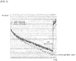
- FIG. 3 is a diagram schematically illustrating a voltage change curve of each battery unit 10 in which a voltage deviation between battery units 10 is corrected after the IR drop depending on a time.
- the apparatus 100 for sensing opening of a current interrupt device of a battery unit according to the embodiment of the present invention corrects the voltage deviation through the correcting unit 120 as illustrated in FIG. 3 , and as a result, all of the voltage values at the voltage drop points of time of the respective batter units 10 are equal to each other to accurately compare a voltage reduction amount per time and acquire the battery unit 10 in which the current interrupt device is opened and the number of the battery cells 11 based on the compared voltage reduction amounts.
- the measuring unit 130 measures a voltage section pass time which is the time when one or more battery units 10 pass through the predetermined voltage section for each battery unit 10.
- the voltage section pass time of each battery unit 10 is a value for acquiring a normalized coefficient and the normalized coefficient will be described below.
- the detecting unit 140 may detect the battery unit 10 in which the interrupt in which the current interrupt device is opened among one or more battery units 10 based on the voltage section pass time for each battery unit 10 and detect the number of battery cells 11 in which the current interrupt device is opened among one or more battery cells 11 included in the battery unit 10 in which the current interrupt device is opened.
- the detecting unit 140 may find a maximum value among the voltage values of one or more respective battery units 10 and compare the maximum value and a lowerlimit value of the predetermined voltage section. In the case where the maximum value among the voltage values of the respective battery units 10 is smaller than the lowerlimit value of the predetermined voltage section, the case may mean that the corresponding battery unit 10 passes through the voltage section, and as a result, measurement of the voltage section pass time for each corresponding battery unit 10 ends.
- the detecting unit 140 may calculate a normalized count which is a percentage of the voltage section pass time of the battery unit 10 to an average of the voltage section pass time of all of one or more battery units 10 for each battery unit 10 when the maximum value is smaller than the lowerlimit value.
- X represents the normalized coefficient
- A represents the voltage section pass time of each battery unit, which is measured by the measuring unit
- B represents the average of the voltage section pass time of all battery units.
- the detecting unit 140 compares the normalized coefficient and a predetermined reference value to detect the battery unit 10 in which the current interrupt device is opened among one or more battery units 10 and the number of battery cells 11 in which the current interrupt device is opened among one or more battery cells 11 included in the battery unit 10 in which the current interrupt device is opened.
- the predetermined reference value may be a value acquired by dividing the voltage section pass time by the number of cells based on 100.
- the detecting unit 140 may determine the number of battery cells in which the current interrupt device is opened based on the predetermined reference value of Table 1 including the normalized coefficient of Table 2. For example, since the normalized count of the sixth battery unit 10 is 77 in Table 2, the detecting unit 140 may detect 5 which is the number of battery cells 11 in which the current interrupt device is opened when the predetermined reference value is 77 or more and less than 81.
- ⁇ Table 1> Predetermined reference value The number of battery cells in which current interrupt device is opened 96 or more 0 92 or more and less than 96 1 88 or more and less than 92 2 85 or more and less than 88 3 81 or more and less than 85 4 77 or more and less than 81 5 74 or more and less than 77 6 70 or more and less than 74 7 66 or more and less than 70 8 62 or more and less than 66 9 59 or more and less than 62 10 55 or more and less than 59 11 51 or more and less than 55 12 48 or more and less than 51 13 44 or more and less than 48 14 40 or more and less than 44 15 37 or more and less than 40 16 33 or more and less than 37 17 29 or more and less than 33 18 25 or more and less than 29 19 22 or more and less than 25 20 18 or more and less than 22 21 14 or more and less than 18 22 11 or more and less than 14 23 7 or more and less than 11 24 3 or more and less than 7 25 0 or more and less than 3 26
- the display unit 150 may display a warning message indicating that the current interrupt device is opened when a ratio of the number of battery cells 11 in which the current interrupt device is opened among one or more battery cells 11 included in the battery unit 10 in which the current interrupt device is opened is equal to or more than a predetermined value.
- the battery user may know a risk situation while viewing the display unit 150 and only when the ratio of the battery cells 11 in which the current interrupt device is opened is higher as the predetermined value is higher, the warning message is displayed, and as a result, the predetermined value may be approximately 40%.
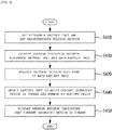
- FIG. 4 is a flowchart for describing a method for sensing opening of a current interrupt device of a battery unit according to an embodiment of the present invention.
- step S410 is a step which may be performed by the setting unit 110 described in FIG. 1 and herein, since a description of the setting unit 110 is adopted, a duplicated description is omitted.
- step (S420) is a step which may be performed by the correcting unit 120 described in FIG. 1 and herein, since the description of the correcting unit 120 is adopted, the duplicated description is omitted.
- step (S430) is a step which may be performed by the measuring unit 130 described in FIG. 1 and herein, since the description of the measuring unit 130 is followed, the duplicated description is omitted.
- step S440 is a step which may be performed by the detecting unit 140 described in FIG. 1 and herein, since the description of the detecting unit 140 is followed, the duplicated description is omitted.
- step S450 is a step which may be performed by the display unit 150 described in FIG. 1 and herein, since the description of the display unit 150 is followed, the duplicated description is omitted.
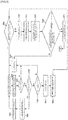
- FIG. 5 is a flowchart for specifically describing a method for sensing opening of a current interrupt device of a battery unit according to an embodiment of the present invention.
- steps S501, S502, S503, and S504 are steps which may be performed by the setting unit 110 described in FIG. 1 and herein, since the description of the setting unit 110 is followed, the duplicated description is omitted.
- step S505 is a step which may be performed by the correcting unit 120 described in FIG. 1 and herein, since the description of the correcting unit 120 is followed, the duplicated description is omitted.
- the voltage section pass time of each battery unit is measured (S508), and the maximum value among the voltage values of the respective battery units and the lowerlimit value of a predetermined voltage section are compared with each other (S509), and when the lowerlimit value of the predetermined voltage section is larger than the maximum value among the voltage values of the battery units, the normalized coefficient of each battery unit is calculated (S510).
- the normalized coefficient and the predetermined reference value are compared with each other (S511) to detect the battery unit in which the current interrupt device is opened and the number of battery cells in which the corresponding battery unit is opened (S512).
- step S506, S507, S508, S509, S510, S511, and S512 are steps which may be performed by the detecting unit 140 described in FIG. 1 and herein, since the description of the detecting unit 140 is followed, the duplicated description is omitted.
- steps S513 and S514 are steps which may be performed by the display unit 150 described in FIG. 1 and herein, since the description of the display unit 150 is followed, the duplicated description is omitted.
Landscapes
- Engineering & Computer Science (AREA)
- Physics & Mathematics (AREA)
- General Physics & Mathematics (AREA)
- Power Engineering (AREA)
- Manufacturing & Machinery (AREA)
- Chemical & Material Sciences (AREA)
- Chemical Kinetics & Catalysis (AREA)
- Electrochemistry (AREA)
- General Chemical & Material Sciences (AREA)
- General Engineering & Computer Science (AREA)
- Secondary Cells (AREA)
- Charge And Discharge Circuits For Batteries Or The Like (AREA)
Description
- Documents
JP2014-236652 WO 2013/176087 ,EP 2 343 768 ,WO 2013/176085 , andUS8629687 relate to apparatus for sensing opening of a current interrupt device of a battery unit which constitute relevant technological background. - The present invention relates to an apparatus and a method for sensing opening of a current interrupt device (CID) of a battery unit, and particularly, to an apparatus and a method for sensing opening of a current interrupt device (CID) of a battery unit, which accurately detect a battery unit in which a current interrupt device is opened among one or more battery units and the number of one or more battery cells included in the battery unit in which the current interrupt device is opened by setting a predetermined voltage section, and set a reference battery unit and add voltage difference values between the
- Further, the present invention also relates to an apparatus and a method for sensing opening of a current interrupt device of a battery unit, which announces a warning message indicating that a current interrupt device is opened to a user when the number of battery cells in which the current interrupt device is opened is more than a predetermined ratio to reduce a risk of ignition.
- A secondary battery is universally applied to an electric vehicle (EV) driven by an electric driving source, a hybrid vehicle (HV) or an energy storage system (ESS) or an uninterruptible power supply (UPS) system using a medium/large battery used for a house or an industry as well as a portable device.
- When the secondary battery is implemented as a battery of a portable terminal, or the like, it may not particularly be applied as above, but in the case of the battery applied to the electric vehicle or an energy storage source, unit secondary battery cells are generally aggregated and used to increase suitability for a high-capacity environment.
- The secondary battery stores and further, discharges energy while charging/discharging and further, overcharging of the secondary battery may generally cause a danger in safety due to a characteristic that the energy is accumulated. When an in-cell overcharge phenomenon of the secondary battery occurs, an air pore of a separator positioned between cathode and anode materials with an increase of temperature in the cell is closed, and as a result, a phenomenon in which the battery cell is swelled may occur and an explosion phenomenon may occur.
- Therefore, a safety circuit against the overcharge is particularly provided in a battery device, and as a result, a device is required, which prevents further charging before the battery is ignited and exploded while charging and a device that interrupts current which flows on the cell of the secondary battery is referred to as a current interrupt device (CID).
- Meanwhile, since overdischarge of the battery reduces life-span durability of the battery due to a characteristic in which the energy is consumed, the current interrupt device operates when not only the battery is overcharged but also the battery is overdischarged and when a battery user uses the battery while not recognizing that the current interrupt device is opened while discharging the battery, more excessive current than the battery cells included in another battery unit may flow in the battery cells included in the battery unit in which the current interrupt device is opened, and as a result, there is a risk of the ignition.
- Therefore, an apparatus that can sense whether the current interrupt device is opened during discharging of the battery is required for the battery together with the current interrupt device, but in the related art, the apparatus that that senses whether the current interrupt device of the battery cell is opened does not exist during the discharging of the battery and the battery user may not know whether the current interrupt device is opened, and as a result, the battery user is exposed to the risk of the ignition.
- In the present invention, when the battery is discharged, a situation in which the current interrupt device is opened is immediately announced to the user to allow the user to take an action against the corresponding situation in advance, thereby preventing a safety situation such as the ignition.
- An object of the present invention is to provide an apparatus and a method for sensing opening of a current interrupt device (CID) of a battery unit, which accurately detect a battery unit in which a current interrupt device is opened among one or more battery units and the number of one or more battery cells included in the battery unit in which the current interrupt device is opened by setting a predetermined voltage section, and set a reference battery unit and add voltage difference values between the reference battery unit and one or more respective battery units to each battery unit voltage value to prevent an opening sensing error of the current interrupt device due to a voltage imbalance between the respective battery units.
- Another object of the present invention is to provide an apparatus and a method for sensing opening of a current interrupt device of a battery unit, which announce a warning message indicating that a current interrupt device is opened to a user when the number of battery cells in which the current interrupt device is opened is more than a predetermined ratio to reduce a risk of ignition.
- An apparatus for sensing opening of a current interrupt device of a battery unit according to an embodiment of the present invention is configured to include: a setting unit setting a predetermined voltage section when discharge of one or more battery units starts; a measuring unit measuring a voltage section pass time which is the time when the one or more battery units pass through the predetermined voltage section for each battery unit; and a detecting unit detecting a battery unit in which the current interrupt device (CID) is opened among the one or more battery units based on the voltage section pass time for each battery unit and detecting the number of battery cells in which the CID is opened among one or more battery cells included in the battery unit in which the CID is opened.
- The setting unit may set any one of the one or more battery units which are discharged as a reference battery unit when discharge of the one or more battery units starts and set the predetermined voltage section based on a voltage value of the reference battery unit when a predetermined time elapses after the discharge starts.
- The apparatus for sensing opening of a current interrupt device of a battery unit may further include a correcting unit calculating a voltage difference between the voltage of the reference battery unit when the predetermined time elapses and the voltage of each of the one or more battery units and adding the voltage difference value to the voltage value of each of the one or more battery units.
- The detecting unit may find a maximum value among the voltage values of the one or more respective battery units and compare the maximum value and a lowerlimit value of the predetermined voltage section.
- The detecting unit may calculate a normalized count which is a percentage of the voltage section pass time of the battery unit to an average of the voltage section pass time of all of one or more battery units for each battery unit when the maximum value is smaller than the lowerlimit value.
- The detecting unit may compare the normalized coefficient and a predetermined reference value with each other to detect the battery unit in which the CID is opened among the one or more battery units and the number of battery cells in which the CID is opened among one or more battery cells included in the battery unit in which the CID is opened.
- The apparatus for sensing opening of a current interrupt device of a battery unit may further include a display unit displaying a warning message indicating that the CID is opened when a ratio of the number of battery cells in which the CID is opened among one or more battery cells included in the battery unit in which the CID is opened is equal to or more than a predetermined value.
- A method for sensing opening of a current interrupt device of a battery unit according to an embodiment of the present invention is configured to include: setting a predetermined voltage section when discharge of one or more battery units starts; measuring a voltage section pass time which is the time when the one or more battery units pass through the predetermined voltage section for each battery unit; and detecting a battery unit in which the current interrupt device (CID) is opened among the one or more battery units based on the voltage section pass time for each battery unit and detecting the number of battery cells in which the CID is opened among one or more battery cells included in the battery unit in which the CID is opened.
- The setting may include setting any one of the one or more battery units which are discharged as a reference battery unit when discharge of the one or more battery units starts and setting the predetermined voltage section based on a voltage value of the reference battery unit when a predetermined time elapses after the discharge starts.
- The method for sensing opening of a current interrupt device of a battery unit may further include calculating a difference between the voltage of the reference battery unit when the predetermined time elapses and the voltage of each of the one or more battery units and adding the voltage difference value to the voltage value of each of the one or more battery units.
- The detecting may include finding a maximum value among the voltage values of the one or more respective battery units and comparing the maximum value and a lowerlimit value of the predetermined voltage section.
- The detecting may further include calculating a normalized count which is a percentage of the voltage section pass time of the battery unit to an average of the voltage section pass time of all of one or more battery units for each battery unit when the maximum value is smaller than the lowerlimit value.
- The detecting may further include comparing the normalized coefficient and a predetermined reference value with each other to detect the battery unit in which the CID is opened among the one or more battery units and the number of battery cells in which the CID is opened among one or more battery cells included in the battery unit in which the CID is opened.
- The method for sensing opening of a current interrupt device of a battery unit may further include displaying a warning message indicating that the CID is opened when a ratio of the number of battery cells in which the CID is opened among one or more battery cells included in the battery unit in which the CID is opened is equal to or more than a predetermined value.
- According to an aspect of the present invention, it is possible to provide an apparatus and a method for sensing opening of a current interrupt device (CID) of a battery unit, which accurately detect a battery unit in which a current interrupt device is opened among one or more battery units and the number of one or more battery cells included in the battery unit in which the current interrupt device is opened by setting a predetermined voltage section, and set a reference batter unit and add voltage difference values between the reference battery unit and one or more respective battery units to each battery unit voltage value to prevent an opening sensing error of the current interrupt device due to a voltage imbalance between the respective battery units.
- Further, it is possible to provide an apparatus and a method for sensing opening of a current interrupt device of a battery unit, which announce a warning message indicating that a current interrupt device is opened to a user when the number of battery cells in which the current interrupt device is opened is more than a predetermined ratio to reduce a risk of ignition.
-
-
FIG. 1 is a diagram schematically illustrating an apparatus for sensing opening of a current interrupt device (CID) of a battery unit according to an embodiment of the present invention. - FIG. 2 (absent from the Drawings) is a diagram schematically illustrating a voltage change curve depending on a time of each battery unit in a state where IR drop occurs and a voltage deviation between battery units is not corrected.
-
FIG. 3 is a diagram schematically illustrating a voltage change curve of each battery unit in which a voltage deviation between battery units is corrected after IR drop occurs depending on a time. -
FIG. 4 is a flowchart for schematically describing a method for sensing opening of a current interrupt device of a battery unit according to an embodiment of the present invention. -
FIG. 5 is a flowchart for specifically describing a method for sensing opening of a current interrupt device of a battery unit according to an embodiment of the present invention. - An apparatus for sensing opening of a current interrupt device of a battery unit according to an embodiment of the present invention is configured to include: a setting unit setting a predetermined voltage section when discharge of one or more battery units starts; a measuring unit measuring a voltage section pass time which is the time when the one or more battery units pass through the predetermined voltage section for each battery unit; and a detecting unit detecting a battery unit in which the current interrupt device (CID) is opened among the one or more battery units and detecting the number of battery cells in which the CID is opened among one or more battery cells included in the battery unit in which the CID is opened based on the voltage section pass time for each battery unit.
- The present invention will be described below in detail with reference to the accompanying drawings. Herein, a repeated description, and a detailed description of a known function and a known constitution which may unnecessarily obscure the spirit of the present invention will be skipped. The embodiment of the present invention is provided to more completely describe the present invention to those skilled in the art. Accordingly, the shape, the size, etc., of elements in the figures may be exaggerated for more explicit comprehension.
- Throughout the specification, unless explicitly described to the contrary, the word "comprise" and variations such as "comprises" or "comprising", will be understood to imply the inclusion of stated elements but not the exclusion of any other elements.
- In addition, the term "unit" disclosed in the specification means a unit that processes at least one function or operation and this may be implemented by hardware or software or a combination of hardware and software.
-
FIG. 1 is a diagram schematically illustrating anapparatus 100 for sensing opening of a current interrupt device (CID) of a battery unit according to an exemplary embodiment of the present invention. - Referring to
FIG. 1 , theapparatus 100 for sensing opening of a current interrupt device of a battery unit according to the embodiment of the present invention announces to a battery user whether a current interrupt device (not illustrated) connected with abattery cell 11 is opened. Theapparatus 100 for sensing opening of a current interrupt device of a battery unit according to the embodiment of the present invention may be implemented by asetting unit 110, a correctingunit 120, ameasuring unit 130, a detectingunit 140, and adisplay unit 150. - The
apparatus 100 for sensing opening of a current interrupt device of a battery unit, which is illustrated inFIG. 1 follows the embodiment and components are not limited to the embodiment illustrated inFIG. 1 and some components may be added, changed, or deleted as necessary. - Herein, the type of
battery unit 10 is not particularly limited and thebattery unit 10 may be constituted by for example, a battery module, a battery pack, a battery rack, a battery bank, and the like. - The
setting unit 110 may set a predetermined voltage section when discharge of one ormore battery units 10 starts. The predetermined voltage section is set to accurately detect the number ofbattery cells 11 in which the current interrupt device is opened and a method for accurately detecting the number ofbattery cells 11 in which the current interrupt device is opened will be described below. - Further, the
setting unit 110 may set nay one of one ormore battery units 10 which are discharged as areference batter unit 10 when the discharge of one ormore battery units 10 starts and set the predetermined voltage section based on a voltage value of thereference battery unit 10 when a predetermined time is reached after the discharge starts. In the case of thereference battery unit 10, any one of one ormore battery units 10 which are discharged may be set as thereference battery unit 10 and as necessary, the battery user may designate thereference battery unit 10. - A process of setting the predetermined voltage section based on the voltage value of the
reference battery unit 10 is determined through an experiment and an upperlimit value of the predetermined voltage section needs to be lower than an initial voltage value of thereference battery unit 10. - The correcting
unit 120 may calculate a difference between the voltage of thereference battery unit 10 and the voltage of each of one ormore battery units 10 when the predetermined time is reached and add the voltage difference value to the voltage value of each of one ormore battery units 10. When the voltage difference value is added to the voltage value of each of one ormore battery units 10, the corresponding value coincides with the voltage value of thereference battery unit 10 and this is referred to as voltage deviation correction between thebattery units 10. When the voltage deviation between thebattery units 10 is corrected, all of the voltage values at voltage drop points of time of therespective battery units 10 are equal to each other to accurately determine a voltage reduction amount per time for eachbattery unit 10. - The IR drop is also referred to as ohmic drop and when current meets resistance, the voltage drops and the IR drop represents that the voltage difference between a first part and an end part occurs when a wire is long. The predetermined time is set to correct voltage after the IR drop and in general, since the IR drop occurs before 2 seconds, the predetermined time may be set to 2 seconds.
- FIG. 2 (absent from the Drawings) is a diagram schematically illustrating a voltage change curve depending on a time of each
battery unit 10 in a state where IR drop occurs and a voltage deviation betweenbattery units 10 is not corrected. In the state illustrated in FIG. 2, it is difficult to accurately detect abattery unit 10 in which the current interrupt device is opened among one ormore battery units 10 and the number ofbattery cells 11 in which the current interrupt device is opened among one ormore battery cells 11 included in thebattery unit 10 in which the current interrupt device is opened due to the voltage deviation between thebattery units 10. -
FIG. 3 is a diagram schematically illustrating a voltage change curve of eachbattery unit 10 in which a voltage deviation betweenbattery units 10 is corrected after the IR drop depending on a time. Theapparatus 100 for sensing opening of a current interrupt device of a battery unit according to the embodiment of the present invention corrects the voltage deviation through the correctingunit 120 as illustrated inFIG. 3 , and as a result, all of the voltage values at the voltage drop points of time of therespective batter units 10 are equal to each other to accurately compare a voltage reduction amount per time and acquire thebattery unit 10 in which the current interrupt device is opened and the number of thebattery cells 11 based on the compared voltage reduction amounts. - The measuring
unit 130 measures a voltage section pass time which is the time when one ormore battery units 10 pass through the predetermined voltage section for eachbattery unit 10. The voltage section pass time of eachbattery unit 10 is a value for acquiring a normalized coefficient and the normalized coefficient will be described below. - The detecting
unit 140 may detect thebattery unit 10 in which the interrupt in which the current interrupt device is opened among one ormore battery units 10 based on the voltage section pass time for eachbattery unit 10 and detect the number ofbattery cells 11 in which the current interrupt device is opened among one ormore battery cells 11 included in thebattery unit 10 in which the current interrupt device is opened. - Further, the detecting
unit 140 may find a maximum value among the voltage values of one or morerespective battery units 10 and compare the maximum value and a lowerlimit value of the predetermined voltage section. In the case where the maximum value among the voltage values of therespective battery units 10 is smaller than the lowerlimit value of the predetermined voltage section, the case may mean that the correspondingbattery unit 10 passes through the voltage section, and as a result, measurement of the voltage section pass time for eachcorresponding battery unit 10 ends. - When the detecting
unit 140 may calculate a normalized count which is a percentage of the voltage section pass time of thebattery unit 10 to an average of the voltage section pass time of all of one ormore battery units 10 for eachbattery unit 10 when the maximum value is smaller than the lowerlimit value. The normalized coefficient may be calculated by using Equation 1 given below.
- Where, X represents the normalized coefficient, A represents the voltage section pass time of each battery unit, which is measured by the measuring unit, and B represents the average of the voltage section pass time of all battery units.
- In the embodiment, the detecting
unit 140 compares the normalized coefficient and a predetermined reference value to detect thebattery unit 10 in which the current interrupt device is opened among one ormore battery units 10 and the number ofbattery cells 11 in which the current interrupt device is opened among one ormore battery cells 11 included in thebattery unit 10 in which the current interrupt device is opened. The predetermined reference value may be a value acquired by dividing the voltage section pass time by the number of cells based on 100. Hereinafter, one example in which the detectingunit 140 detects thebattery unit 10 in which the current interrupt device is opened and the number ofbattery cells 11 in which the current interrupt device is opened will be described with reference to Tables 1 and 2. - A more detailed predetermined reference value and the number of
battery cells 11 in which the current interrupt device is opened, which corresponds thereto are disclosed in Table 1 given below. The detectingunit 140 may determine the number of battery cells in which the current interrupt device is opened based on the predetermined reference value of Table 1 including the normalized coefficient of Table 2. For example, since the normalized count of thesixth battery unit 10 is 77 in Table 2, the detectingunit 140 may detect 5 which is the number ofbattery cells 11 in which the current interrupt device is opened when the predetermined reference value is 77 or more and less than 81.<Table 1> Predetermined reference value The number of battery cells in which current interrupt device is opened 96 or more 0 92 or more and less than 96 1 88 or more and less than 92 2 85 or more and less than 88 3 81 or more and less than 85 4 77 or more and less than 81 5 74 or more and less than 77 6 70 or more and less than 74 7 66 or more and less than 70 8 62 or more and less than 66 9 59 or more and less than 62 10 55 or more and less than 59 11 51 or more and less than 55 12 48 or more and less than 51 13 44 or more and less than 48 14 40 or more and less than 44 15 37 or more and less than 40 16 33 or more and less than 37 17 29 or more and less than 33 18 25 or more and less than 29 19 22 or more and less than 25 20 18 or more and less than 22 21 14 or more and less than 18 22 11 or more and less than 14 23 7 or more and less than 11 24 3 or more and less than 7 25 0 or more and less than 3 26 <Table 2> Voltage section pass time Normalized count The number of battery cells in which current interrupt device is opened 1st battery 152 99 0 2nd battery 160 104 0 3rd battery 157 102 0 4th battery 151 98 0 5th battery 156 101 0 6th battery 119 77 5 7th battery 156 101 0 8th battery 159 103 0 9th battery 159 103 0 10th battery 160 104 0 11th battery 156 101 0 12th battery 156 101 0 13th battery 154 100 0 - The
display unit 150 may display a warning message indicating that the current interrupt device is opened when a ratio of the number ofbattery cells 11 in which the current interrupt device is opened among one ormore battery cells 11 included in thebattery unit 10 in which the current interrupt device is opened is equal to or more than a predetermined value. The battery user may know a risk situation while viewing thedisplay unit 150 and only when the ratio of thebattery cells 11 in which the current interrupt device is opened is higher as the predetermined value is higher, the warning message is displayed, and as a result, the predetermined value may be approximately 40%. -
FIG. 4 is a flowchart for describing a method for sensing opening of a current interrupt device of a battery unit according to an embodiment of the present invention. - Referring to
FIG. 4 , when the method for sensing opening of a current interrupt device of abattery unit 10 according to the embodiment of the present invention starts, the predetermined voltage section is set based on thereference battery unit 10 and the voltage value of thereference battery unit 10 at the time when the predetermined time is reached (S410). A process of step S410 is a step which may be performed by thesetting unit 110 described inFIG. 1 and herein, since a description of thesetting unit 110 is adopted, a duplicated description is omitted. - In addition, the voltage deviation between the
reference battery unit 10 and eachbattery unit 10 is added to eachbattery unit 10 to correct the voltage deviation as the voltage value of the reference battery unit 10 (S420). A process of step (S420) is a step which may be performed by the correctingunit 120 described inFIG. 1 and herein, since the description of the correctingunit 120 is adopted, the duplicated description is omitted. - Then, the voltage section pass time of each
battery unit 10 is measured (S430). The voltage section pass time of eachbattery unit 10 is an element for acquiring the normalized coefficient. The process of step (S430) is a step which may be performed by the measuringunit 130 described inFIG. 1 and herein, since the description of the measuringunit 130 is followed, the duplicated description is omitted. - Then, the
battery unit 10 in which the current interrupt device is opened and the number ofbattery cells 11 included in thebattery unit 10 in which the current interrupt device is opened are detected by comparing the normalized coefficient and the predetermined reference value with each other (S440). The process of step S440 is a step which may be performed by the detectingunit 140 described inFIG. 1 and herein, since the description of the detectingunit 140 is followed, the duplicated description is omitted. - In addition, the warning message indicating that the current interrupt device is opened is displayed in order to transfer the risk situation to the battery user (S450). The process of step S450 is a step which may be performed by the
display unit 150 described inFIG. 1 and herein, since the description of thedisplay unit 150 is followed, the duplicated description is omitted. -
FIG. 5 is a flowchart for specifically describing a method for sensing opening of a current interrupt device of a battery unit according to an embodiment of the present invention. - Referring to
FIG. 5 , when the method for sensing opening of a current interrupt device of a battery unit according to the embodiment of the present invention starts, the voltage of each battery unit is stored (S501), it is determined whether each battery unit is discharged (S502), and thereafter, when the predetermined time elapses (S503), the predetermined voltage section is set based on the voltage value of the reference battery unit (S504). The processes of steps S501, S502, S503, and S504 are steps which may be performed by thesetting unit 110 described inFIG. 1 and herein, since the description of thesetting unit 110 is followed, the duplicated description is omitted. - In addition, the voltage deviation is corrected based on the voltage value of the reference battery unit (S505). The process of step S505 is a step which may be performed by the correcting
unit 120 described inFIG. 1 and herein, since the description of the correctingunit 120 is followed, the duplicated description is omitted. - Then, when the predetermined time elapsed (S506), the maximum value among the voltage values of the respective battery units is found (S507), the voltage section pass time of each battery unit is measured (S508), and the maximum value among the voltage values of the respective battery units and the lowerlimit value of a predetermined voltage section are compared with each other (S509), and when the lowerlimit value of the predetermined voltage section is larger than the maximum value among the voltage values of the battery units, the normalized coefficient of each battery unit is calculated (S510). The normalized coefficient and the predetermined reference value are compared with each other (S511) to detect the battery unit in which the current interrupt device is opened and the number of battery cells in which the corresponding battery unit is opened (S512). The processes of step S506, S507, S508, S509, S510, S511, and S512 are steps which may be performed by the detecting
unit 140 described inFIG. 1 and herein, since the description of the detectingunit 140 is followed, the duplicated description is omitted. - In addition, when the ratio of the battery cells in which the current interrupt device is opened among the battery cells included in the battery unit in which the current interrupt device is opened is equal to or more than a predetermined value (S513), the warning message indicating that the current interrupt device is opened is displayed (S514). The processes of steps S513 and S514 are steps which may be performed by the
display unit 150 described inFIG. 1 and herein, since the description of thedisplay unit 150 is followed, the duplicated description is omitted. - Hereinabove, a specific embodiment of the present invention has been illustrated and described, but the present invention and the accompanying drawings are not limited to the accompanying drawings and the described contents and it is apparent to those skilled in the art that various modifications of the present invention can be made within the scope of the claims.
Claims (14)
- An apparatus for sensing opening of a current interrupt device of a battery unit (10), comprising:a setting unit (110) configured to set a predetermined voltage section when discharge of one or more battery units (10) starts;anda detecting unit (140);characterized in that it further comprises a measuring unit (130) configured to measure a voltage section pass time which is the time when the one or more battery units (10) pass through the predetermined voltage section for each battery unit (10); and in that the detecting unit (140) is configured to detect a battery unit (10) in which the current interrupt device (CID) is opened among the one or more battery units (10) based on the voltage section pass time for each battery unit (10) and to detect the number of battery cells (11) in which the CID is opened among one or more battery cells (11) included in the battery unit (10) in which the CID is opened.
- The apparatus of claim 1, wherein the setting unit is configured to set any one of the one or more battery units which are discharged as a reference battery unit when discharge of the one or more battery units starts and to set the predetermined voltage section based on a voltage value of the reference battery unit when a predetermined time elapses after the discharge starts.
- The apparatus of claim 2, further comprising:
a correcting unit configured to calculate a difference between the voltage of the reference battery unit when the predetermined time elapses and the voltage of each of the one or more battery units and to add the voltage difference value to the voltage value of each of the one or more battery units to accurately determine a voltage reduction amount per time for each battery unit. - The apparatus of claim 3, wherein the detecting unit is configured to find a maximum value among the voltage values of the one or more respective battery units and to compare the maximum value and a lowerlimit value of the predetermined voltage section.
- The apparatus of claim 4, wherein the detecting unit is configured to calculate a normalized count which is a percentage of the voltage section pass time of the battery unit to an average of the voltage section pass time of all of the one or more battery units for each battery unit when the maximum value is smaller than the lowerlimit value.
- The apparatus of claim 5, wherein the detecting unit is configured to compare the normalized coefficient and a predetermined reference value with each other to detect the battery unit in which the CID is opened among the one or more battery units and the number of battery cells in which the CID is opened among one or more battery cells included in the battery unit in which the CID is opened.
- The apparatus of claim 6, further comprising: a display unit configured to display a warning message indicating that the CID is opened when a ratio of the number of battery cells in which the CID is opened among one or more battery cells included in the battery unit in which the CID is opened is equal to or more than a predetermined value.
- A method for sensing opening of a current interrupt device of a battery unit, comprising:setting a predetermined voltage section when discharge of one or more battery units starts;measuring a voltage section pass time which is the time when the one or more battery units pass through the predetermined voltage section for each battery unit; anddetecting a battery unit in which the current interrupt device (CID) is opened among the one or more battery units based on the voltage section pass time for each battery unit and detecting the number of battery cells in which the CID is opened among one or more battery cells included in the battery unit in which the CID is opened.
- The method of claim 8, wherein the setting includes setting any one of the one or more battery units which are discharged as a reference battery unit when discharge of the one or more battery units starts and setting the predetermined voltage section based on a voltage value of the reference battery unit when a predetermined time elapses after the discharge starts.
- The method of claim 9, further comprising:
calculating a difference between the voltage of the reference battery unit when the predetermined time elapses and the voltage of each of the one or more battery units and adding the voltage difference value to the voltage value of each of the one or more battery units to accurately determine a voltage reduction amount per time for each battery unit. - The method of claim 10, wherein the detecting includes finding a maximum value among the voltage values of the one or more respective battery units and comparing the maximum value and a lowerlimit value of the predetermined voltage section.
- The method of claim 11, wherein the detecting further includes calculating a normalized count which is a percentage of the voltage section pass time of the battery unit to an average of the voltage section pass time of all of one or more battery units for each battery unit when the maximum value is smaller than the lowerlimit value.
- The method of claim 12, wherein the detecting further includes comparing the normalized coefficient and a predetermined reference value with each other to detect the battery unit in which the CID is opened among the one or more battery units and the number of battery cells in which the CID is opened among one or more battery cells included in the battery unit in which the CID is opened.
- The method of claim 13, further comprising:
displaying a warning message indicating that the CID is opened when a ratio of the number of battery cells in which the CID is opened among one or more battery cells included in the battery unit in which the CID is opened is equal to or more than a predetermined value.
Applications Claiming Priority (2)
| Application Number | Priority Date | Filing Date | Title |
|---|---|---|---|
| KR1020150013434A KR101757969B1 (en) | 2015-01-28 | 2015-01-28 | Device and method for detecting opening of current interrupt device of battery unit |
| PCT/KR2016/000962 WO2016122239A1 (en) | 2015-01-28 | 2016-01-28 | Apparatus and method for sensing opening of current interrupt device of battery unit |
Publications (3)
| Publication Number | Publication Date |
|---|---|
| EP3252914A1 EP3252914A1 (en) | 2017-12-06 |
| EP3252914A4 EP3252914A4 (en) | 2018-10-17 |
| EP3252914B1 true EP3252914B1 (en) | 2019-07-24 |
Family
ID=56543767
Family Applications (1)
| Application Number | Title | Priority Date | Filing Date |
|---|---|---|---|
| EP16743717.7A Active EP3252914B1 (en) | 2015-01-28 | 2016-01-28 | Apparatus and method for sensing opening of current interrupt device of battery unit |
Country Status (4)
| Country | Link |
|---|---|
| US (1) | US10365307B2 (en) |
| EP (1) | EP3252914B1 (en) |
| KR (1) | KR101757969B1 (en) |
| WO (1) | WO2016122239A1 (en) |
Cited By (1)
| Publication number | Priority date | Publication date | Assignee | Title |
|---|---|---|---|---|
| DE102022128702B3 (en) | 2022-10-28 | 2024-02-01 | Webasto SE | Method for determining a proportion of defective battery cells, a battery control device, a computer program, a computer-readable storage medium, a battery and a motor vehicle |
Families Citing this family (4)
| Publication number | Priority date | Publication date | Assignee | Title |
|---|---|---|---|---|
| JP7042128B2 (en) * | 2018-03-26 | 2022-03-25 | 日立Astemo株式会社 | Voltage detector |
| FR3101199B1 (en) * | 2019-09-25 | 2022-07-01 | Renault Sas | Protection system of an internal variable resistance device |
| KR102733356B1 (en) * | 2019-10-02 | 2024-11-22 | 주식회사 엘지에너지솔루션 | Method and system for detecting connection failure in parallel connection cell |
| KR102733355B1 (en) * | 2019-10-02 | 2024-11-25 | 주식회사 엘지에너지솔루션 | Method and system for detecting connection failure in parallel connection cell |
Family Cites Families (11)
| Publication number | Priority date | Publication date | Assignee | Title |
|---|---|---|---|---|
| JP5675045B2 (en) * | 2008-11-26 | 2015-02-25 | 三洋電機株式会社 | Battery system |
| US8629687B2 (en) * | 2009-04-24 | 2014-01-14 | Yazaki Corporation | Disconnection detecting device |
| JP2011135657A (en) | 2009-12-22 | 2011-07-07 | Sanyo Electric Co Ltd | Battery system and vehicle with the same, and method for detecting current limit state of the battery system |
| JP5601089B2 (en) | 2010-08-23 | 2014-10-08 | ミツミ電機株式会社 | Protection circuit and protection circuit IC |
| JP5949146B2 (en) | 2012-05-22 | 2016-07-06 | 株式会社豊田自動織機 | Battery state determination method, battery control device, and battery pack |
| JP5949147B2 (en) * | 2012-05-22 | 2016-07-06 | 株式会社豊田自動織機 | Battery state determination method, battery control device, and battery pack |
| JP5596083B2 (en) * | 2012-06-26 | 2014-09-24 | Imv株式会社 | Lithium-ion secondary battery deterioration diagnosis device |
| KR20140017043A (en) | 2012-07-24 | 2014-02-11 | 삼성에스디아이 주식회사 | Current breaking device and battery pack having the same |
| KR20140073627A (en) | 2012-11-30 | 2014-06-17 | 주식회사 포스코아이씨티 | Apparatus and Method for Managing Battery |
| JP5708668B2 (en) * | 2013-01-18 | 2015-04-30 | トヨタ自動車株式会社 | Power storage system |
| JP6032135B2 (en) | 2013-06-05 | 2016-11-24 | トヨタ自動車株式会社 | Power storage system |
-
2015
- 2015-01-28 KR KR1020150013434A patent/KR101757969B1/en active Active
-
2016
- 2016-01-28 EP EP16743717.7A patent/EP3252914B1/en active Active
- 2016-01-28 US US15/519,975 patent/US10365307B2/en active Active
- 2016-01-28 WO PCT/KR2016/000962 patent/WO2016122239A1/en not_active Ceased
Non-Patent Citations (1)
| Title |
|---|
| None * |
Cited By (2)
| Publication number | Priority date | Publication date | Assignee | Title |
|---|---|---|---|---|
| DE102022128702B3 (en) | 2022-10-28 | 2024-02-01 | Webasto SE | Method for determining a proportion of defective battery cells, a battery control device, a computer program, a computer-readable storage medium, a battery and a motor vehicle |
| EP4361655A1 (en) | 2022-10-28 | 2024-05-01 | Webasto SE | Method for determining a part of defective battery cells, a battery control device, a computer program, a computer-readable storage medium, a battery and a motor vehicle |
Also Published As
| Publication number | Publication date |
|---|---|
| EP3252914A4 (en) | 2018-10-17 |
| KR101757969B1 (en) | 2017-07-14 |
| US10365307B2 (en) | 2019-07-30 |
| EP3252914A1 (en) | 2017-12-06 |
| WO2016122239A1 (en) | 2016-08-04 |
| US20170328936A1 (en) | 2017-11-16 |
| KR20160092711A (en) | 2016-08-05 |
Similar Documents
| Publication | Publication Date | Title |
|---|---|---|
| US11456610B2 (en) | Internal short sensing battery control apparatus and battery control method | |
| EP3252914B1 (en) | Apparatus and method for sensing opening of current interrupt device of battery unit | |
| EP3396808B1 (en) | Battery protection device and battery protection method | |
| JP4739040B2 (en) | Secondary battery internal short-circuit detection device, secondary battery internal short-circuit detection method, secondary battery pack and electronic device | |
| KR102123675B1 (en) | Method for proctect overcharg, overdischargge and efficiency increasing of battery pack | |
| US12119695B2 (en) | Device and method for detecting poor battery cell | |
| US20120176092A1 (en) | Battery capacity detection device of lithium ion rechargeable battery | |
| US11774510B2 (en) | Apparatus and method for detecting low-voltage defective battery cell | |
| US20150355286A1 (en) | System for estimating failure in cell module | |
| EP3396774A1 (en) | Method and system for effective battery cell balancing through duty control | |
| JP2002325363A (en) | Battery pack and battery pack failure diagnosis method | |
| CN101504996A (en) | Charging apparatus and charging method | |
| KR102350920B1 (en) | device for detecting the state of charge of a battery | |
| JP2017167034A (en) | Deterioration determination device and deterioration determination method | |
| WO2015178075A1 (en) | Battery control device | |
| WO2019181138A1 (en) | Device for measuring degree of deterioration of secondary battery | |
| EP2779356B1 (en) | Battery pack, charging circuit, and charging device | |
| JP5203270B2 (en) | Secondary battery capacity test system and secondary battery capacity test method | |
| CN107110917A (en) | Method and supervising device for monitoring battery pack | |
| JP2018137058A (en) | Battery device and battery device control method | |
| JP2018129896A (en) | Battery Management Unit | |
| JP2012125121A (en) | Charging system and storage battery degradation determination method | |
| US20150212163A1 (en) | Device for detecting remaining battery capacity, battery system, method of detecting remaining battery capacity and program | |
| JP2010164322A (en) | Method and device for detecting remaining capacity of battery, and secondary battery system | |
| KR20190091037A (en) | Apparatus for preventing overcharge, shortening of lifetime and explosion of lithium battery for drone and the method thereof |
Legal Events
| Date | Code | Title | Description |
|---|---|---|---|
| STAA | Information on the status of an ep patent application or granted ep patent |
Free format text: STATUS: THE INTERNATIONAL PUBLICATION HAS BEEN MADE |
|
| PUAI | Public reference made under article 153(3) epc to a published international application that has entered the european phase |
Free format text: ORIGINAL CODE: 0009012 |
|
| STAA | Information on the status of an ep patent application or granted ep patent |
Free format text: STATUS: REQUEST FOR EXAMINATION WAS MADE |
|
| 17P | Request for examination filed |
Effective date: 20170425 |
|
| AK | Designated contracting states |
Kind code of ref document: A1 Designated state(s): AL AT BE BG CH CY CZ DE DK EE ES FI FR GB GR HR HU IE IS IT LI LT LU LV MC MK MT NL NO PL PT RO RS SE SI SK SM TR |
|
| AX | Request for extension of the european patent |
Extension state: BA ME |
|
| DAV | Request for validation of the european patent (deleted) | ||
| DAX | Request for extension of the european patent (deleted) | ||
| RIC1 | Information provided on ipc code assigned before grant |
Ipc: H01M 10/48 20060101ALN20180905BHEP Ipc: H02H 7/18 20060101ALN20180905BHEP Ipc: G01R 31/36 20060101ALI20180905BHEP Ipc: G01R 31/02 20060101ALN20180905BHEP Ipc: H02J 7/00 20060101AFI20180905BHEP Ipc: G01R 31/28 20060101ALI20180905BHEP Ipc: G01R 19/165 20060101ALI20180905BHEP |
|
| A4 | Supplementary search report drawn up and despatched |
Effective date: 20180913 |
|
| REG | Reference to a national code |
Ref country code: DE Ref legal event code: R079 Ref document number: 602016017400 Country of ref document: DE Free format text: PREVIOUS MAIN CLASS: H02J0007000000 Ipc: G01R0019165000 |
|
| GRAP | Despatch of communication of intention to grant a patent |
Free format text: ORIGINAL CODE: EPIDOSNIGR1 |
|
| STAA | Information on the status of an ep patent application or granted ep patent |
Free format text: STATUS: GRANT OF PATENT IS INTENDED |
|
| RIC1 | Information provided on ipc code assigned before grant |
Ipc: G01R 31/28 20060101ALI20190211BHEP Ipc: H02H 3/04 20060101ALI20190211BHEP Ipc: G01R 19/165 20060101AFI20190211BHEP Ipc: G01R 31/3835 20190101ALI20190211BHEP Ipc: G01R 31/02 20060101ALN20190211BHEP |
|
| INTG | Intention to grant announced |
Effective date: 20190228 |
|
| GRAS | Grant fee paid |
Free format text: ORIGINAL CODE: EPIDOSNIGR3 |
|
| GRAA | (expected) grant |
Free format text: ORIGINAL CODE: 0009210 |
|
| STAA | Information on the status of an ep patent application or granted ep patent |
Free format text: STATUS: THE PATENT HAS BEEN GRANTED |
|
| AK | Designated contracting states |
Kind code of ref document: B1 Designated state(s): AL AT BE BG CH CY CZ DE DK EE ES FI FR GB GR HR HU IE IS IT LI LT LU LV MC MK MT NL NO PL PT RO RS SE SI SK SM TR |
|
| REG | Reference to a national code |
Ref country code: GB Ref legal event code: FG4D |
|
| REG | Reference to a national code |
Ref country code: CH Ref legal event code: EP |
|
| REG | Reference to a national code |
Ref country code: DE Ref legal event code: R096 Ref document number: 602016017400 Country of ref document: DE |
|
| REG | Reference to a national code |
Ref country code: AT Ref legal event code: REF Ref document number: 1158802 Country of ref document: AT Kind code of ref document: T Effective date: 20190815 |
|
| REG | Reference to a national code |
Ref country code: IE Ref legal event code: FG4D |
|
| REG | Reference to a national code |
Ref country code: NL Ref legal event code: MP Effective date: 20190724 |
|
| REG | Reference to a national code |
Ref country code: LT Ref legal event code: MG4D |
|
| REG | Reference to a national code |
Ref country code: AT Ref legal event code: MK05 Ref document number: 1158802 Country of ref document: AT Kind code of ref document: T Effective date: 20190724 |
|
| PG25 | Lapsed in a contracting state [announced via postgrant information from national office to epo] |
Ref country code: HR Free format text: LAPSE BECAUSE OF FAILURE TO SUBMIT A TRANSLATION OF THE DESCRIPTION OR TO PAY THE FEE WITHIN THE PRESCRIBED TIME-LIMIT Effective date: 20190724 Ref country code: LT Free format text: LAPSE BECAUSE OF FAILURE TO SUBMIT A TRANSLATION OF THE DESCRIPTION OR TO PAY THE FEE WITHIN THE PRESCRIBED TIME-LIMIT Effective date: 20190724 Ref country code: AT Free format text: LAPSE BECAUSE OF FAILURE TO SUBMIT A TRANSLATION OF THE DESCRIPTION OR TO PAY THE FEE WITHIN THE PRESCRIBED TIME-LIMIT Effective date: 20190724 Ref country code: FI Free format text: LAPSE BECAUSE OF FAILURE TO SUBMIT A TRANSLATION OF THE DESCRIPTION OR TO PAY THE FEE WITHIN THE PRESCRIBED TIME-LIMIT Effective date: 20190724 Ref country code: NO Free format text: LAPSE BECAUSE OF FAILURE TO SUBMIT A TRANSLATION OF THE DESCRIPTION OR TO PAY THE FEE WITHIN THE PRESCRIBED TIME-LIMIT Effective date: 20191024 Ref country code: SE Free format text: LAPSE BECAUSE OF FAILURE TO SUBMIT A TRANSLATION OF THE DESCRIPTION OR TO PAY THE FEE WITHIN THE PRESCRIBED TIME-LIMIT Effective date: 20190724 Ref country code: BG Free format text: LAPSE BECAUSE OF FAILURE TO SUBMIT A TRANSLATION OF THE DESCRIPTION OR TO PAY THE FEE WITHIN THE PRESCRIBED TIME-LIMIT Effective date: 20191024 Ref country code: PT Free format text: LAPSE BECAUSE OF FAILURE TO SUBMIT A TRANSLATION OF THE DESCRIPTION OR TO PAY THE FEE WITHIN THE PRESCRIBED TIME-LIMIT Effective date: 20191125 Ref country code: NL Free format text: LAPSE BECAUSE OF FAILURE TO SUBMIT A TRANSLATION OF THE DESCRIPTION OR TO PAY THE FEE WITHIN THE PRESCRIBED TIME-LIMIT Effective date: 20190724 |
|
| PG25 | Lapsed in a contracting state [announced via postgrant information from national office to epo] |
Ref country code: IS Free format text: LAPSE BECAUSE OF FAILURE TO SUBMIT A TRANSLATION OF THE DESCRIPTION OR TO PAY THE FEE WITHIN THE PRESCRIBED TIME-LIMIT Effective date: 20191124 Ref country code: RS Free format text: LAPSE BECAUSE OF FAILURE TO SUBMIT A TRANSLATION OF THE DESCRIPTION OR TO PAY THE FEE WITHIN THE PRESCRIBED TIME-LIMIT Effective date: 20190724 Ref country code: ES Free format text: LAPSE BECAUSE OF FAILURE TO SUBMIT A TRANSLATION OF THE DESCRIPTION OR TO PAY THE FEE WITHIN THE PRESCRIBED TIME-LIMIT Effective date: 20190724 Ref country code: AL Free format text: LAPSE BECAUSE OF FAILURE TO SUBMIT A TRANSLATION OF THE DESCRIPTION OR TO PAY THE FEE WITHIN THE PRESCRIBED TIME-LIMIT Effective date: 20190724 Ref country code: LV Free format text: LAPSE BECAUSE OF FAILURE TO SUBMIT A TRANSLATION OF THE DESCRIPTION OR TO PAY THE FEE WITHIN THE PRESCRIBED TIME-LIMIT Effective date: 20190724 Ref country code: GR Free format text: LAPSE BECAUSE OF FAILURE TO SUBMIT A TRANSLATION OF THE DESCRIPTION OR TO PAY THE FEE WITHIN THE PRESCRIBED TIME-LIMIT Effective date: 20191025 |
|
| PG25 | Lapsed in a contracting state [announced via postgrant information from national office to epo] |
Ref country code: TR Free format text: LAPSE BECAUSE OF FAILURE TO SUBMIT A TRANSLATION OF THE DESCRIPTION OR TO PAY THE FEE WITHIN THE PRESCRIBED TIME-LIMIT Effective date: 20190724 |
|
| PG25 | Lapsed in a contracting state [announced via postgrant information from national office to epo] |
Ref country code: PL Free format text: LAPSE BECAUSE OF FAILURE TO SUBMIT A TRANSLATION OF THE DESCRIPTION OR TO PAY THE FEE WITHIN THE PRESCRIBED TIME-LIMIT Effective date: 20190724 Ref country code: RO Free format text: LAPSE BECAUSE OF FAILURE TO SUBMIT A TRANSLATION OF THE DESCRIPTION OR TO PAY THE FEE WITHIN THE PRESCRIBED TIME-LIMIT Effective date: 20190724 Ref country code: IT Free format text: LAPSE BECAUSE OF FAILURE TO SUBMIT A TRANSLATION OF THE DESCRIPTION OR TO PAY THE FEE WITHIN THE PRESCRIBED TIME-LIMIT Effective date: 20190724 Ref country code: EE Free format text: LAPSE BECAUSE OF FAILURE TO SUBMIT A TRANSLATION OF THE DESCRIPTION OR TO PAY THE FEE WITHIN THE PRESCRIBED TIME-LIMIT Effective date: 20190724 Ref country code: DK Free format text: LAPSE BECAUSE OF FAILURE TO SUBMIT A TRANSLATION OF THE DESCRIPTION OR TO PAY THE FEE WITHIN THE PRESCRIBED TIME-LIMIT Effective date: 20190724 |
|
| PG25 | Lapsed in a contracting state [announced via postgrant information from national office to epo] |
Ref country code: IS Free format text: LAPSE BECAUSE OF FAILURE TO SUBMIT A TRANSLATION OF THE DESCRIPTION OR TO PAY THE FEE WITHIN THE PRESCRIBED TIME-LIMIT Effective date: 20200224 Ref country code: SM Free format text: LAPSE BECAUSE OF FAILURE TO SUBMIT A TRANSLATION OF THE DESCRIPTION OR TO PAY THE FEE WITHIN THE PRESCRIBED TIME-LIMIT Effective date: 20190724 Ref country code: CZ Free format text: LAPSE BECAUSE OF FAILURE TO SUBMIT A TRANSLATION OF THE DESCRIPTION OR TO PAY THE FEE WITHIN THE PRESCRIBED TIME-LIMIT Effective date: 20190724 Ref country code: SK Free format text: LAPSE BECAUSE OF FAILURE TO SUBMIT A TRANSLATION OF THE DESCRIPTION OR TO PAY THE FEE WITHIN THE PRESCRIBED TIME-LIMIT Effective date: 20190724 |
|
| REG | Reference to a national code |
Ref country code: DE Ref legal event code: R097 Ref document number: 602016017400 Country of ref document: DE |
|
| PLBE | No opposition filed within time limit |
Free format text: ORIGINAL CODE: 0009261 |
|
| STAA | Information on the status of an ep patent application or granted ep patent |
Free format text: STATUS: NO OPPOSITION FILED WITHIN TIME LIMIT |
|
| PG2D | Information on lapse in contracting state deleted |
Ref country code: IS |
|
| 26N | No opposition filed |
Effective date: 20200603 |
|
| PG25 | Lapsed in a contracting state [announced via postgrant information from national office to epo] |
Ref country code: MC Free format text: LAPSE BECAUSE OF FAILURE TO SUBMIT A TRANSLATION OF THE DESCRIPTION OR TO PAY THE FEE WITHIN THE PRESCRIBED TIME-LIMIT Effective date: 20190724 Ref country code: SI Free format text: LAPSE BECAUSE OF FAILURE TO SUBMIT A TRANSLATION OF THE DESCRIPTION OR TO PAY THE FEE WITHIN THE PRESCRIBED TIME-LIMIT Effective date: 20190724 |
|
| REG | Reference to a national code |
Ref country code: CH Ref legal event code: PL |
|
| REG | Reference to a national code |
Ref country code: BE Ref legal event code: MM Effective date: 20200131 |
|
| PG25 | Lapsed in a contracting state [announced via postgrant information from national office to epo] |
Ref country code: LU Free format text: LAPSE BECAUSE OF NON-PAYMENT OF DUE FEES Effective date: 20200128 |
|
| PG25 | Lapsed in a contracting state [announced via postgrant information from national office to epo] |
Ref country code: BE Free format text: LAPSE BECAUSE OF NON-PAYMENT OF DUE FEES Effective date: 20200131 Ref country code: LI Free format text: LAPSE BECAUSE OF NON-PAYMENT OF DUE FEES Effective date: 20200131 Ref country code: CH Free format text: LAPSE BECAUSE OF NON-PAYMENT OF DUE FEES Effective date: 20200131 |
|
| PG25 | Lapsed in a contracting state [announced via postgrant information from national office to epo] |
Ref country code: IE Free format text: LAPSE BECAUSE OF NON-PAYMENT OF DUE FEES Effective date: 20200128 |
|
| PG25 | Lapsed in a contracting state [announced via postgrant information from national office to epo] |
Ref country code: MT Free format text: LAPSE BECAUSE OF FAILURE TO SUBMIT A TRANSLATION OF THE DESCRIPTION OR TO PAY THE FEE WITHIN THE PRESCRIBED TIME-LIMIT Effective date: 20190724 Ref country code: CY Free format text: LAPSE BECAUSE OF FAILURE TO SUBMIT A TRANSLATION OF THE DESCRIPTION OR TO PAY THE FEE WITHIN THE PRESCRIBED TIME-LIMIT Effective date: 20190724 |
|
| PG25 | Lapsed in a contracting state [announced via postgrant information from national office to epo] |
Ref country code: MK Free format text: LAPSE BECAUSE OF FAILURE TO SUBMIT A TRANSLATION OF THE DESCRIPTION OR TO PAY THE FEE WITHIN THE PRESCRIBED TIME-LIMIT Effective date: 20190724 |
|
| P01 | Opt-out of the competence of the unified patent court (upc) registered |
Effective date: 20230512 |
|
| REG | Reference to a national code |
Ref country code: DE Ref legal event code: R081 Ref document number: 602016017400 Country of ref document: DE Owner name: LG ENERGY SOLUTION, LTD., KR Free format text: FORMER OWNER: LG CHEM. LTD., SEOUL, KR |
|
| REG | Reference to a national code |
Ref country code: GB Ref legal event code: 732E Free format text: REGISTERED BETWEEN 20230824 AND 20230831 |
|
| PGFP | Annual fee paid to national office [announced via postgrant information from national office to epo] |
Ref country code: GB Payment date: 20251222 Year of fee payment: 11 |
|
| PGFP | Annual fee paid to national office [announced via postgrant information from national office to epo] |
Ref country code: FR Payment date: 20251223 Year of fee payment: 11 |
|
| PGFP | Annual fee paid to national office [announced via postgrant information from national office to epo] |
Ref country code: DE Payment date: 20251222 Year of fee payment: 11 |