EP3252883A1 - Overtemperature protection for a smart socket - Google Patents
Overtemperature protection for a smart socket Download PDFInfo
- Publication number
- EP3252883A1 EP3252883A1 EP17173280.3A EP17173280A EP3252883A1 EP 3252883 A1 EP3252883 A1 EP 3252883A1 EP 17173280 A EP17173280 A EP 17173280A EP 3252883 A1 EP3252883 A1 EP 3252883A1
- Authority
- EP
- European Patent Office
- Prior art keywords
- smart socket
- power
- temperature
- electric equipment
- smart
- Prior art date
- Legal status (The legal status is an assumption and is not a legal conclusion. Google has not performed a legal analysis and makes no representation as to the accuracy of the status listed.)
- Granted
Links
Images

Classifications
-
- G—PHYSICS
- G08—SIGNALLING
- G08B—SIGNALLING SYSTEMS, e.g. PERSONAL CALLING SYSTEMS; ORDER TELEGRAPHS; ALARM SYSTEMS
- G08B21/00—Alarms responsive to a single specified undesired or abnormal condition and not otherwise provided for
- G08B21/18—Status alarms
- G08B21/24—Reminder alarms, e.g. anti-loss alarms
-
- G—PHYSICS
- G08—SIGNALLING
- G08B—SIGNALLING SYSTEMS, e.g. PERSONAL CALLING SYSTEMS; ORDER TELEGRAPHS; ALARM SYSTEMS
- G08B25/00—Alarm systems in which the location of the alarm condition is signalled to a central station, e.g. fire or police telegraphic systems
- G08B25/01—Alarm systems in which the location of the alarm condition is signalled to a central station, e.g. fire or police telegraphic systems characterised by the transmission medium
- G08B25/10—Alarm systems in which the location of the alarm condition is signalled to a central station, e.g. fire or police telegraphic systems characterised by the transmission medium using wireless transmission systems
-
- G—PHYSICS
- G01—MEASURING; TESTING
- G01R—MEASURING ELECTRIC VARIABLES; MEASURING MAGNETIC VARIABLES
- G01R21/00—Arrangements for measuring electric power or power factor
- G01R21/02—Arrangements for measuring electric power or power factor by thermal methods, e.g. calorimetric
-
- G—PHYSICS
- G08—SIGNALLING
- G08B—SIGNALLING SYSTEMS, e.g. PERSONAL CALLING SYSTEMS; ORDER TELEGRAPHS; ALARM SYSTEMS
- G08B21/00—Alarms responsive to a single specified undesired or abnormal condition and not otherwise provided for
- G08B21/18—Status alarms
- G08B21/182—Level alarms, e.g. alarms responsive to variables exceeding a threshold
-
- G—PHYSICS
- G08—SIGNALLING
- G08B—SIGNALLING SYSTEMS, e.g. PERSONAL CALLING SYSTEMS; ORDER TELEGRAPHS; ALARM SYSTEMS
- G08B25/00—Alarm systems in which the location of the alarm condition is signalled to a central station, e.g. fire or police telegraphic systems
- G08B25/01—Alarm systems in which the location of the alarm condition is signalled to a central station, e.g. fire or police telegraphic systems characterised by the transmission medium
- G08B25/08—Alarm systems in which the location of the alarm condition is signalled to a central station, e.g. fire or police telegraphic systems characterised by the transmission medium using communication transmission lines
-
- H—ELECTRICITY
- H01—ELECTRIC ELEMENTS
- H01R—ELECTRICALLY-CONDUCTIVE CONNECTIONS; STRUCTURAL ASSOCIATIONS OF A PLURALITY OF MUTUALLY-INSULATED ELECTRICAL CONNECTING ELEMENTS; COUPLING DEVICES; CURRENT COLLECTORS
- H01R13/00—Details of coupling devices of the kinds covered by groups H01R12/70 or H01R24/00 - H01R33/00
- H01R13/66—Structural association with built-in electrical component
- H01R13/70—Structural association with built-in electrical component with built-in switch
- H01R13/713—Structural association with built-in electrical component with built-in switch the switch being a safety switch
- H01R13/7137—Structural association with built-in electrical component with built-in switch the switch being a safety switch with thermal interrupter
-
- H—ELECTRICITY
- H04—ELECTRIC COMMUNICATION TECHNIQUE
- H04L—TRANSMISSION OF DIGITAL INFORMATION, e.g. TELEGRAPHIC COMMUNICATION
- H04L12/00—Data switching networks
- H04L12/28—Data switching networks characterised by path configuration, e.g. LAN [Local Area Networks] or WAN [Wide Area Networks]
- H04L12/2803—Home automation networks
- H04L12/2823—Reporting information sensed by appliance or service execution status of appliance services in a home automation network
- H04L12/2825—Reporting to a device located outside the home and the home network
-
- H—ELECTRICITY
- H04—ELECTRIC COMMUNICATION TECHNIQUE
- H04M—TELEPHONIC COMMUNICATION
- H04M1/00—Substation equipment, e.g. for use by subscribers
- H04M1/72—Mobile telephones; Cordless telephones, i.e. devices for establishing wireless links to base stations without route selection
- H04M1/724—User interfaces specially adapted for cordless or mobile telephones
- H04M1/72448—User interfaces specially adapted for cordless or mobile telephones with means for adapting the functionality of the device according to specific conditions
- H04M1/72454—User interfaces specially adapted for cordless or mobile telephones with means for adapting the functionality of the device according to specific conditions according to context-related or environment-related conditions
-
- H—ELECTRICITY
- H02—GENERATION; CONVERSION OR DISTRIBUTION OF ELECTRIC POWER
- H02J—ELECTRIC POWER NETWORKS; CIRCUIT ARRANGEMENTS OR SYSTEMS FOR SUPPLYING OR DISTRIBUTING ELECTRIC POWER; SYSTEMS FOR STORING ELECTRIC ENERGY
- H02J2105/00—Networks for supplying or distributing electric power characterised by their spatial reach or by the load
- H02J2105/10—Local stationary networks having a local or delimited stationary reach
- H02J2105/12—Local stationary networks having a local or delimited stationary reach supplying households or buildings
-
- H—ELECTRICITY
- H02—GENERATION; CONVERSION OR DISTRIBUTION OF ELECTRIC POWER
- H02J—ELECTRIC POWER NETWORKS; CIRCUIT ARRANGEMENTS OR SYSTEMS FOR SUPPLYING OR DISTRIBUTING ELECTRIC POWER; SYSTEMS FOR STORING ELECTRIC ENERGY
- H02J3/00—Circuit arrangements for AC mains or AC distribution networks
- H02J3/12—Arrangements for adjusting voltage in AC networks by changing a characteristic of the network load
- H02J3/14—Arrangements for adjusting voltage in AC networks by changing a characteristic of the network load by switching loads on to, or off from, the networks, e.g. progressively balanced loading
-
- H—ELECTRICITY
- H04—ELECTRIC COMMUNICATION TECHNIQUE
- H04L—TRANSMISSION OF DIGITAL INFORMATION, e.g. TELEGRAPHIC COMMUNICATION
- H04L12/00—Data switching networks
- H04L12/28—Data switching networks characterised by path configuration, e.g. LAN [Local Area Networks] or WAN [Wide Area Networks]
- H04L12/2803—Home automation networks
- H04L2012/284—Home automation networks characterised by the type of medium used
- H04L2012/2841—Wireless
-
- Y—GENERAL TAGGING OF NEW TECHNOLOGICAL DEVELOPMENTS; GENERAL TAGGING OF CROSS-SECTIONAL TECHNOLOGIES SPANNING OVER SEVERAL SECTIONS OF THE IPC; TECHNICAL SUBJECTS COVERED BY FORMER USPC CROSS-REFERENCE ART COLLECTIONS [XRACs] AND DIGESTS
- Y02—TECHNOLOGIES OR APPLICATIONS FOR MITIGATION OR ADAPTATION AGAINST CLIMATE CHANGE
- Y02B—CLIMATE CHANGE MITIGATION TECHNOLOGIES RELATED TO BUILDINGS, e.g. HOUSING, HOUSE APPLIANCES OR RELATED END-USER APPLICATIONS
- Y02B70/00—Technologies for an efficient end-user side electric power management and consumption
- Y02B70/30—Systems integrating technologies related to power network operation and communication or information technologies for improving the carbon footprint of the management of residential or tertiary loads, i.e. smart grids as climate change mitigation technology in the buildings sector, including also the last stages of power distribution and the control, monitoring or operating management systems at local level
-
- Y—GENERAL TAGGING OF NEW TECHNOLOGICAL DEVELOPMENTS; GENERAL TAGGING OF CROSS-SECTIONAL TECHNOLOGIES SPANNING OVER SEVERAL SECTIONS OF THE IPC; TECHNICAL SUBJECTS COVERED BY FORMER USPC CROSS-REFERENCE ART COLLECTIONS [XRACs] AND DIGESTS
- Y02—TECHNOLOGIES OR APPLICATIONS FOR MITIGATION OR ADAPTATION AGAINST CLIMATE CHANGE
- Y02B—CLIMATE CHANGE MITIGATION TECHNOLOGIES RELATED TO BUILDINGS, e.g. HOUSING, HOUSE APPLIANCES OR RELATED END-USER APPLICATIONS
- Y02B70/00—Technologies for an efficient end-user side electric power management and consumption
- Y02B70/30—Systems integrating technologies related to power network operation and communication or information technologies for improving the carbon footprint of the management of residential or tertiary loads, i.e. smart grids as climate change mitigation technology in the buildings sector, including also the last stages of power distribution and the control, monitoring or operating management systems at local level
- Y02B70/3225—Demand response systems, e.g. load shedding, peak shaving
-
- Y—GENERAL TAGGING OF NEW TECHNOLOGICAL DEVELOPMENTS; GENERAL TAGGING OF CROSS-SECTIONAL TECHNOLOGIES SPANNING OVER SEVERAL SECTIONS OF THE IPC; TECHNICAL SUBJECTS COVERED BY FORMER USPC CROSS-REFERENCE ART COLLECTIONS [XRACs] AND DIGESTS
- Y04—INFORMATION OR COMMUNICATION TECHNOLOGIES HAVING AN IMPACT ON OTHER TECHNOLOGY AREAS
- Y04S—SYSTEMS INTEGRATING TECHNOLOGIES RELATED TO POWER NETWORK OPERATION, COMMUNICATION OR INFORMATION TECHNOLOGIES FOR IMPROVING THE ELECTRICAL POWER GENERATION, TRANSMISSION, DISTRIBUTION, MANAGEMENT OR USAGE, i.e. SMART GRIDS
- Y04S20/00—Management or operation of end-user stationary applications or the last stages of power distribution; Controlling, monitoring or operating thereof
- Y04S20/20—End-user application control systems
-
- Y—GENERAL TAGGING OF NEW TECHNOLOGICAL DEVELOPMENTS; GENERAL TAGGING OF CROSS-SECTIONAL TECHNOLOGIES SPANNING OVER SEVERAL SECTIONS OF THE IPC; TECHNICAL SUBJECTS COVERED BY FORMER USPC CROSS-REFERENCE ART COLLECTIONS [XRACs] AND DIGESTS
- Y04—INFORMATION OR COMMUNICATION TECHNOLOGIES HAVING AN IMPACT ON OTHER TECHNOLOGY AREAS
- Y04S—SYSTEMS INTEGRATING TECHNOLOGIES RELATED TO POWER NETWORK OPERATION, COMMUNICATION OR INFORMATION TECHNOLOGIES FOR IMPROVING THE ELECTRICAL POWER GENERATION, TRANSMISSION, DISTRIBUTION, MANAGEMENT OR USAGE, i.e. SMART GRIDS
- Y04S20/00—Management or operation of end-user stationary applications or the last stages of power distribution; Controlling, monitoring or operating thereof
- Y04S20/20—End-user application control systems
- Y04S20/222—Demand response systems, e.g. load shedding, peak shaving
Definitions
- the present disclosure generally relates to the technical field of communications, and more particularly, to an information prompting method and device.
- Smart sockets usually refer to sockets with built-in Wireless Fidelity (WI-FI) modules and capable of being remotely controlled to switch on and off through clients installed on mobile terminals, and a user may control switching-on/off of a smart socket through a mobile client.
- WI-FI Wireless Fidelity
- the present disclosure provides an information prompting method and device, in accordance with claims which follow.
- an information prompting method including:
- the temperature in the smart socket is acquired, the temperature in the smart socket is compared with the preset temperature threshold value, it is determined whether the power of the electric equipment connected with the smart socket is higher than the upper limit of the acceptable power range of the smart socket according to the comparison result, the alarming information indicating that the power of the electric equipment is excessively high is generated when the power of the electric equipment is determined to be higher than the upper limit of the acceptable power range of the smart socket, and the alarming information is finally pushed to the mobile terminal bound with the smart socket.
- the alarming information is pushed to the mobile terminal, so that a prompt may be remotely given.
- acquiring the temperature in the smart socket may include that:
- the temperature in the smart socket may be acquired from the temperature sensor in the smart socket, so that easiness for implementation is ensured.
- acquiring the temperature in the smart socket may include that:
- the temperature in the smart socket during working of the electric equipment may be acquired, the electric equipment is connected with the smart socket, and since only the temperature in the smart socket during working of the electric equipment is acquired, resource waste caused by real-time acquisition and comparison may be avoided.
- comparing the temperature in the smart socket with the preset temperature threshold value and determining whether the power of the electric equipment connected with the smart socket is higher than the upper limit of the acceptable power range of the smart socket according to the comparison result may include that:
- the temperature in the smart socket is compared with the preset temperature threshold value
- the power of the electric equipment connected with the smart socket may be determined to be higher than the upper limit of the acceptable power range of the smart socket when the temperature in the smart socket is more than or equal to the preset temperature threshold value, thus a power metering device is not required to be arranged in the smart socket, so that cost for power determination is reduced.
- the method may further include that:
- the operation instruction for cutting off the power is sent to the smart socket to timely control the smart socket to perform the operation of cutting off the power, so that the user is prompted to check the electric equipment, thus it is possible to overcome the shortcomings of potential safety hazards and shortening of the service life of the smart socket due to the excessively high power of the electric equipment, and in addition, loss caused by the excessively high power is avoided.
- an information prompting device including:
- the temperature acquisition module may include:
- the temperature acquisition module may include:
- the power determination module may include:
- the device may further include:
- an information prompting device including:
- the steps of the information prompting method are determined by computer program instructions.
- the disclosure is also directed to a computer program for executing the steps of an information prompting method as described above when this program is executed by a computer.
- This program can use any programming language and take the form of source code, object code or a code intermediate between source code and object code, such as a partially compiled form, or any other desirable form.
- the disclosure is also directed to a computer-readable information medium containing instructions of a computer program as described above.
- the information medium can be any entity or device capable of storing the program.
- the support can include storage means such as a ROM, for example a CD ROM or a microelectronic circuit ROM, or magnetic storage means, for example a diskette (floppy disk) or a hard disk.
- the information medium can be an integrated circuit in which the program is incorporated, the circuit being adapted to execute the method in question or to be used in its execution.
- first, second, third and the like may be adopted to describe various kinds of information in the present disclosure but these information may not be limited to these terms. These terms are only adopted to distinguish the same type of information.
- first information may also be called second information, and similarly, second information may also be called first information. This depends on the context, and for example, term “if” adopted here may be explained as “at the time of” or "when” or "in response to determination”.
- Smart home equipment is more and more applied to people's daily lives, and taking a smart socket as an example, a user may control switching-on/off of the smart socket through a mobile terminal, herein the mobile terminal involved in the present disclosure may be a smart mobile phone, a tablet computer, a Personal Digital Assistant (PDA), an E-book reader, a multimedia player, a smart band, smart eyeglasses and the like.
- a mobile terminal herein the mobile terminal involved in the present disclosure may be a smart mobile phone, a tablet computer, a Personal Digital Assistant (PDA), an E-book reader, a multimedia player, a smart band, smart eyeglasses and the like.
- PDA Personal Digital Assistant
- the mobile terminal may directly control the smart socket, and for example, the smart socket provides an access point and the mobile terminal searches for the access point and is connected with the smart socket; and for another example, the mobile terminal provides an access point and the smart socket searches for the access point and is connected with the mobile terminal.
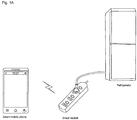
- Fig. 1A is an application scenario diagram of an information prompting method, according to an exemplary embodiment of the present disclosure.
- the mobile terminal is a smart mobile phone and electric equipment is a refrigerator.
- the smart socket provides an access point, the smart mobile phone searches for the access point and is connected with the smart socket, and the smart mobile phone sends a switching control instruction to control switching-on/off of the smart socket.
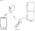
- the mobile terminal may also remotely control the smart socket through a server and a router, the mobile terminal transmits a control instruction to the server, and the server transmits the instruction to the smart socket.
- Fig. 1B is an application scenario diagram of another information prompting method, according to an exemplary embodiment of the present disclosure.
- the mobile terminal is a smart mobile phone and the electric equipment is a refrigerator.
- the present disclosure provides an information prompting method
- the information prompting method may be applied to the server in the application scenario, and the server acquires temperature in the smart socket, generates alarming information indicating that power of the electric equipment is excessively high when determining that the power of the electric equipment is higher than an upper limit of an acceptable power range of the smart socket according to the temperature, and pushes the alarming information to the mobile terminal bound with the smart socket.
- the information prompting method may also be applied to the smart socket in the application scenarios, and the smart socket acquires the temperature detected by a temperature sensor, generates alarming information indicating that the power of the electric equipment is excessively high when determining that the power of the electric equipment is higher than the upper limit of the acceptable power range of the smart socket according to the temperature, and directly pushes the alarming information to the mobile terminal bound with the smart socket, or uploads the alarming information to the server for the server to push to the mobile terminal bound with the smart socket.
- the information prompting method provided by the present disclosure will be introduced below.
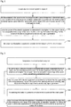
- Fig. 2 is a flow chart showing an information prompting method, according to an exemplary embodiment of the present disclosure, and as shown in Fig. 2 , the method includes the following Step 201 to Step 204.
- Step 201 temperature in a smart socket is acquired.
- the temperature in the smart socket may be acquired in real time, and the temperature in the smart socket may also be acquired when a preset temperature acquisition condition is met.
- the preset temperature acquisition condition may be that set time is reached, may also be that a time interval is reached, and may further be that the smart socket is at an on position and the like.
- Acquiring the temperature in the smart socket when the smart socket is at the on position may avoid resource waste caused by real-time acquisition and avoid untimely acquisition caused by regular acquisition.
- electric equipment connected with the smart socket may be in a working state and may also be in a non-working state when the smart socket is at the on position and the temperature in the smart socket is usually not so high when the electric equipment is in the non-working state, the temperature may not be required to be detected.
- the temperature in the smart socket during working of the electric equipment may be acquired in Step 201, and the electric equipment is connected with the smart socket. Obviously, only acquiring the temperature in the smart socket during working of the electric equipment may avoid resource waste caused by acquisition and comparison.
- the electric equipment may be determined to be in the working state and the temperature in the smart socket may be acquired when a control instruction, sent by a mobile terminal, of starting the electric equipment is detected in a scenario where the mobile terminal is bound with the electric equipment, herein, in the scenario where the mobile terminal is bound with the electric equipment, the electric equipment may be smart home equipment, and the mobile terminal may control starting, switching-off, running mode and the like of the electric equipment.
- the electric equipment may be determined to be in the working state when a current value in the smart socket is detected to be higher than a set current threshold value.
- the temperature in the smart socket may be acquired from a temperature sensor in the smart socket, that is, the temperature detected by the temperature sensor in the smart socket is acquired, herein the temperature sensor may be arranged on a circuit board of the smart socket, and may also be arranged on an inner shell and the like of the smart socket.
- the temperature sensor may be a built-in sensor of a micro-controller of the smart socket. Since the temperature is directly acquired from the temperature sensor in the micro-controller without additionally arranging a temperature sensor in the smart socket, cost may be reduced.
- Step 202 the temperature in the smart socket is compared with a preset temperature threshold value, and it is determined whether power of electric equipment connected with the smart socket is higher than an upper limit of an acceptable power range of the smart socket according to a comparison result.
- the preset temperature threshold value may be a preset threshold value configured to determine whether the power of the electric equipment is higher than the upper limit of the acceptable power range of the smart socket.
- whether the temperature in the smart socket is more than or equal to the preset temperature threshold value may be determined, and when the temperature in the smart socket is more than or equal to the preset temperature threshold value, the power of the electric equipment connected with the smart socket may be determined to be higher than the upper limit of the acceptable power range of the smart socket; and when the temperature in the smart socket is lower than the preset temperature threshold value, the power of the electric equipment connected with the smart socket may be determined not to be higher than the upper limit of the acceptable power range of the smart socket.
- the temperature in the smart socket is compared with the preset temperature threshold value
- the power of the electric equipment connected with the smart socket may be determined to be higher than the upper limit of the acceptable power range of the smart socket when the temperature in the smart socket is more than or equal to the preset temperature threshold value, thus a power metering device is not required to be arranged in the smart socket, so that cost for power determination is reduced.
- Step 203 when the power of the electric equipment is determined to be higher than the upper limit of the acceptable power range of the smart socket, alarming information indicating that the power of the electric equipment is excessively high is generated.
- the alarming information indicating that the power of the electric equipment is excessively high may be generated to prompt a user to check the electric equipment according to the event that the power of the electric equipment is higher than the upper limit of the acceptable power range of the smart socket when the power of the electric equipment is determined to be higher than the upper limit of the acceptable power range of the smart socket.
- the electric equipment may still work normally and an obvious dangerous accident may not happen temporally when the power of the electric equipment is higher than the upper limit of the acceptable power range of the smart socket, so that the user may usually be unconscious, and huge loss may be caused as time goes on.
- the alarming information indicating that the power of the electric equipment is excessively high is generated to prompt the user and make the user know an alarming reason and directly check whether the power of the electric equipment is higher than the upper limit of the acceptable power range of the smart socket to avoid the phenomenon that the user who does not know the alarming reason only performs simple checking and omits checking and timely treatment of a real hidden danger to probably cause huge loss.
- Step 204 the alarming information is pushed to a mobile terminal bound with the smart socket.
- the alarming information may be pushed to the mobile terminal bound with the smart socket to remotely give a prompt, and then the user having the mobile terminal may timely check the smart socket and the electric equipment to avoid loss.
- remote prompt may be implemented, and it is possible to avoid potential safety hazards caused by the excessively high power of the electric equipment after the user remotely controls the smart socket to switch on.
- the temperature in the smart socket is acquired, the temperature in the smart socket is compared with the preset temperature threshold value, it is determined whether the power of the electric equipment connected with the smart socket is higher than the upper limit of the acceptable power range of the smart socket according to the comparison result, and the power metering device is not required to be smart socket, so that the power determination cost is reduced.
- the alarming information indicating that the power of the electric equipment is excessively high is generated when the power of the electric equipment is determined to be higher than the upper limit of the acceptable power range of the smart socket, and the alarming information is finally pushed to the mobile terminal bound with the smart socket, In this way, a user is remotely prompted, so that it is possible to avoid the potential safety hazards caused by the excessively high power of the electric equipment, and avoid service life of the smart socket to be shortened due to the excessively high power of the electric equipment.
- Fig. 3 is a flow chart showing an information prompting method, according to an exemplary embodiment of the present disclosure, and as shown in Fig. 3 , the method includes the following steps:
- Step 301 to Step 304 and Step 201 to Step 204 are the same, and will not be elaborated herein one by one.
- Step 305 when the power of the electric equipment is determined to be higher than the upper limit of the acceptable power range of the smart socket, the operation instruction for cutting off the power may be sent to the smart socket to control the smart socket to perform the operation of cutting off the power to timely avoid occurrence of a danger.
- the temperature in the smart socket is acquired, the temperature in the smart socket is compared with the preset temperature threshold value, it is determined whether the power of the electric equipment connected with the smart socket is higher than the upper limit of the acceptable power range of the smart socket according to the comparison result, the alarming information indicating that the power of the electric equipment is excessively high is generated when the power of the electric equipment is determined to be higher than the upper limit of the acceptable power range of the smart socket, and the alarming information is finally pushed to the mobile terminal bound with the smart socket to remotely prompt a user to check the electric equipment to overcome the shortcomings of potential safety hazards and shortening of service life of the smart socket due to the excessively high power of the electric equipment; and in addition, the operation instruction for cutting off the power is sent to the smart socket to timely control the smart socket to perform the operation of cutting off the power, so that loss caused by the excessively high power is avoided.
- the present disclosure further provides embodiments regarding an information prompting device and a terminal applied by it.
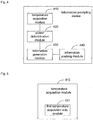
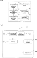
- Fig. 4 is a block diagram of an information prompting device, according to an exemplary embodiment of the present disclosure, and as shown in Fig. 4 , the device includes: a temperature acquisition module 410, a power determination module 420, an information generation module 430 and an information pushing module 440.
- the temperature acquisition module 410 is configured to acquire temperature in a smart socket;
- the power determination module 420 is configured to compare the temperature in the smart socket with a preset temperature threshold value, and determine whether power of electric equipment connected with the smart socket is higher than an upper limit of an acceptable power range of the smart socket according to a comparison result;
- the information generation module 430 is configured to, when the power of the electric equipment is determined to be higher than the upper limit of the acceptable power range of the smart socket, generate alarming information indicating that the power of the electric equipment is excessively high;
- the information pushing module 440 is configured to push the alarming information to a mobile terminal bound with the smart socket.
- the temperature in the smart socket is acquired, the temperature in the smart socket is compared with the preset temperature threshold value, it is determined whether the power of the electric equipment connected with the smart socket is higher than the upper limit of the acceptable power range of the smart socket according to the comparison result, the alarming information indicating that the power of the electric equipment is excessively high is generated when the power of the electric equipment is determined to be higher than the upper limit of the acceptable power range of the smart socket, and the alarming information is finally pushed to the mobile terminal bound with the smart socket. a user is prompted to check the electric equipment, so that it is possible to avoid potential safety hazards caused by the excessively high power of the electric equipment, and avoid service life of the smart socket to be shortened due to the excessively high power of the electric equipment.
- Fig. 5 is a block diagram of another information prompting device, according to an exemplary embodiment of the present disclosure, and as shown in Fig. 5 , based on the embodiment shown in Fig. 4 , the temperature acquisition module 410 in the embodiment includes: a first temperature acquisition sub-module 411.
- the first temperature acquisition sub-module 411 is configured to acquire the temperature in the smart socket from a temperature sensor in the smart socket.
- the temperature in the smart socket may be acquired from the temperature sensor in the smart socket, so that easiness for implementation is ensured.
- Fig. 6 is a block diagram of another information prompting device, according to an exemplary embodiment of the present disclosure, and as shown in Fig. 6 , based on the embodiment shown in Fig. 4 , the temperature acquisition module 410 in the embodiment includes: a second temperature acquisition sub-module 412.
- the second temperature acquisition sub-module 412 is configured to acquire the temperature in the smart socket during working of the electric equipment, the electric equipment being connected with the smart socket.
- Fig. 7 is a block diagram of an information prompting device, according to an exemplary embodiment of the present disclosure, and as shown in Fig. 7 , based on the embodiment shown in Fig. 4 , the power determination module 420 in the embodiment includes: a power determination sub-module 421.
- the power determination sub-module 421 is configured to, when the temperature in the smart socket is more than or equal to the preset temperature threshold value, determine that the power of the electric equipment connected with the smart socket is higher than the upper limit of the acceptable power range of the smart socket.
- the temperature in the smart socket is compared with the preset temperature threshold value
- the power of the electric equipment connected with the smart socket may be determined to be higher than the upper limit of the acceptable power range of the smart socket when the temperature in the smart socket is more than or equal to the preset temperature threshold value, thus a power metering device is not required to be arranged in the smart socket, so that cost for power determination is reduced.
- Fig. 8 is a block diagram of another information prompting device, according to an exemplary embodiment of the present disclosure, and as shown in Fig. 8 , based on the embodiments shown in any one of Fig. 4 to Fig. 7 , the device in the embodiment further includes: a power control module 450.
- the power control module 450 is configured to, when the power of the electric equipment is determined to be higher than the upper limit of the acceptable power range of the smart socket, send an operation instruction for cutting off power to the smart socket to control the smart socket to perform operation of cutting off the power.
- the operation instruction for cutting off the power is sent to the smart socket to timely control the smart socket to perform the operation of cutting off the power, so that the user is prompted to check the electric equipment, thus it is possible to overcome the shortcomings of potential safety hazards and shortening of the service life of the smart socket due to the excessively high power of the electric equipment, and in addition, loss caused by the excessively high power is avoided.
- the present disclosure further provides an information prompting device, and the device includes a processor; and a memory for storing instructions executable by the processor, herein the processor is configured to:
- the device embodiments substantially correspond to the method embodiments, related parts refer to part of descriptions in the method embodiments.
- the device embodiments described above are only schematic, in which the modules described as separate parts may or may not be physically separated and the parts displayed as modules may or may not be physical modules and namely may be located in the same place or distributed to multiple network modules.
- the purpose of the solutions of the present disclosure may be achieved by selecting part or all of the modules according to a practical requirement, which may be understood and implemented by those skilled in the art without any creative work.
- Fig. 9 is a block diagram of an information prompting device 900, according to an exemplary embodiment.
- the device 900 may be provided as a server.
- the device 900 includes a processing component 922, which further includes one or more processors and a memory resource represented by a memory 932 for storing instructions, such as applications, executable by the processing component 922.
- the applications stored in the memory 932 may include one or more than one module of which each corresponds to a set of instructions.
- the processing component 922 is configured to execute the instructions to implement the abovementioned information prompting method.
- the device 900 may further include a power component 926 configured to perform power mangement of the device 900, a wired or wireless network interface 950 configured to connect the device 900 to a network, and an Input/Output (I/O) interface 958.
- the device 900 may be operated on the basis of an operating system stored in the memory 1932, such as Windows ServerTM, Mac OS XTM, UnixTM, LinuxTM or FreeBSDTM.
- the temperature in the smart socket is acquired, the temperature in the smart socket is compared with the preset temperature threshold value, it is determined whether the power of the electric equipment connected with the smart socket is higher than the upper limit of the acceptable power range of the smart socket according to the comparison result, the alarming information indicating that the power of the electric equipment is excessively high is generated when the power of the electric equipment is determined to be higher than the upper limit of the acceptable power range of the smart socket, and the alarming information is finally pushed to the mobile terminal bound with the smart socket.
- the alarming information is pushed to the mobile terminal, so that a prompt may be remotely given.
- the temperature in the smart socket may be acquired from the temperature sensor in the smart socket, so that easiness for implementation is ensured.
- the temperature in the smart socket during working of the electric equipment may be acquired, the electric equipment is connected with the smart socket, and since only the temperature in the smart socket during working of the electric equipment is acquired, resource waste caused by real-time acquisition and comparison may be avoided.
- the temperature in the smart socket is compared with the preset temperature threshold value
- the power of the electric equipment connected with the smart socket may be determined to be higher than the upper limit of the acceptable power range of the smart socket when the temperature in the smart socket is more than or equal to the preset temperature threshold value, thus a power metering device is not required to be arranged in the smart socket, so that cost for power determination is reduced.
- the operation instruction for cutting off the power is sent to the smart socket to timely control the smart socket to perform the operation of cutting off the power, so that the user is prompted to check the electric equipment, thus it is possible to overcome the shortcomings of potential safety hazards and shortening of the service life of the smart socket due to the excessively high power of the electric equipment, and in addition, loss caused by the excessively high power is avoided.
Landscapes
- Engineering & Computer Science (AREA)
- Physics & Mathematics (AREA)
- General Physics & Mathematics (AREA)
- Business, Economics & Management (AREA)
- Emergency Management (AREA)
- Computer Networks & Wireless Communication (AREA)
- Automation & Control Theory (AREA)
- Signal Processing (AREA)
- Power Engineering (AREA)
- Environmental & Geological Engineering (AREA)
- Human Computer Interaction (AREA)
- Emergency Alarm Devices (AREA)
- Telephone Function (AREA)
- Power Sources (AREA)
Abstract
Description
- The present disclosure generally relates to the technical field of communications, and more particularly, to an information prompting method and device.
- Along with continuous development of electronic technologies, smart home equipment emerges, and smart home equipment is increasingly applied to people's daily lives and work, and brings more and more convenience to people's lives. Particularly, smart sockets are widely applied. Smart sockets usually refer to sockets with built-in Wireless Fidelity (WI-FI) modules and capable of being remotely controlled to switch on and off through clients installed on mobile terminals, and a user may control switching-on/off of a smart socket through a mobile client.
- However, when electric equipment with excessive power is plugged into a smart socket for work, although the electric equipment may be powered through the smart socket to work normally, it is dangerous, and service life of the smart service is shortened.
- Accordingly, the present disclosure provides an information prompting method and device, in accordance with claims which follow.
- According to a first aspect of the embodiment of the present disclosure, there is provided an information prompting method, including:
- acquiring temperature in a smart socket;
- comparing the temperature in the smart socket with a preset temperature threshold value, and determining whether power of electric equipment connected with the smart socket is higher than an upper limit of an acceptable power range of the smart socket according to a comparison result;
- when the power of the electric equipment is determined to be higher than the upper limit of the acceptable power range of the smart socket, generating alarming information indicating that the power of the electric equipment is excessively high; and
- pushing the alarming information to a mobile terminal bound with the smart socket.
- According to the present disclosure, the temperature in the smart socket is acquired, the temperature in the smart socket is compared with the preset temperature threshold value, it is determined whether the power of the electric equipment connected with the smart socket is higher than the upper limit of the acceptable power range of the smart socket according to the comparison result, the alarming information indicating that the power of the electric equipment is excessively high is generated when the power of the electric equipment is determined to be higher than the upper limit of the acceptable power range of the smart socket, and the alarming information is finally pushed to the mobile terminal bound with the smart socket. In this way, a user is prompted to check the electric equipment, so that it is possible to avoid potential safety hazards caused by the excessively high power of the electric equipment, and avoid service life of the smart socket to be shortened due to the excessively high power of the electric equipment. In addition, the alarming information is pushed to the mobile terminal, so that a prompt may be remotely given.
- According to an exemplary embodiment, acquiring the temperature in the smart socket may include that:
- acquiring the temperature in the smart socket from a temperature sensor in the smart socket.
- According to the present disclosure, the temperature in the smart socket may be acquired from the temperature sensor in the smart socket, so that easiness for implementation is ensured.
- According to an exemplary embodiment, acquiring the temperature in the smart socket may include that:
- acquiring the temperature in the smart socket during working of the electric equipment, the electric equipment being connected with the smart socket.
- According to the present disclosure, the temperature in the smart socket during working of the electric equipment may be acquired, the electric equipment is connected with the smart socket, and since only the temperature in the smart socket during working of the electric equipment is acquired, resource waste caused by real-time acquisition and comparison may be avoided.
- According to an exemplary embodiment, comparing the temperature in the smart socket with the preset temperature threshold value and determining whether the power of the electric equipment connected with the smart socket is higher than the upper limit of the acceptable power range of the smart socket according to the comparison result may include that:
- when the temperature in the smart socket is more than or equal to the preset temperature threshold value, determining that the power of the electric equipment connected with the smart socket is higher than the upper limit of the acceptable power range of the smart socket.
- According to the present disclosure, the temperature in the smart socket is compared with the preset temperature threshold value, the power of the electric equipment connected with the smart socket may be determined to be higher than the upper limit of the acceptable power range of the smart socket when the temperature in the smart socket is more than or equal to the preset temperature threshold value, thus a power metering device is not required to be arranged in the smart socket, so that cost for power determination is reduced.
- According to an exemplary embodiment, the method may further include that:
- when the power of the electric equipment is determined to be higher than the upper limit of the acceptable power range of the smart socket, sending an operation instruction for cutting off power to the smart socket to control the smart socket to perform an operation of cutting off the power.
- According to the present disclosure, when the power of the electric equipment is determined to be higher than the upper limit of the acceptable power range of the smart socket, not only the alarming information indicating that the power of the electric equipment is excessively high is generated, but also the alarming information is pushed to the mobile terminal bound with the smart socket, and in addition, the operation instruction for cutting off the power is sent to the smart socket to timely control the smart socket to perform the operation of cutting off the power, so that the user is prompted to check the electric equipment, thus it is possible to overcome the shortcomings of potential safety hazards and shortening of the service life of the smart socket due to the excessively high power of the electric equipment, and in addition, loss caused by the excessively high power is avoided.
- According to a second aspect of the embodiment of the present disclosure, there is provided an information prompting device, including:
- a temperature acquisition module configured to acquire temperature in a smart socket;
- a power determination module configured to compare the temperature in the smart socket with a preset temperature threshold value, and determine whether power of electric equipment connected with the smart socket is higher than an upper limit of an acceptable power range of the smart socket according to a comparison result;
- an information generation module configured to, when the power of the electric equipment is determined to be higher than the upper limit of the acceptable power range of the smart socket, generate alarming information indicating that the power of the electric equipment is excessively high; and
- an information pushing module configured to push the alarming information to a mobile terminal bound with the smart socket.
- The advantages and technical effects of the device according to the invention correspond to those of the method presented above.
- According to a particular embodiment, the temperature acquisition module may include:
- a first temperature acquisition sub-module configured to acquire the temperature in the smart socket from a temperature sensor in the smart socket.
- According to a particular embodiment, the temperature acquisition module may include:
- a second temperature acquisition sub-module configured to acquire the temperature in the smart socket during working of the electric equipment, the electric equipment being connected with the smart socket.
- According to a particular embodiment, the power determination module may include:
- a power determination sub-module configured to, when the temperature in the smart socket is more than or equal to the preset temperature threshold value, determine that the power of the electric equipment connected with the smart socket is higher than the upper limit of the acceptable power range of the smart socket.
- According to a particular embodiment, the device may further include:
- a power control module configured to, when the power of the electric equipment is determined to be higher than the upper limit of the acceptable power range of the smart socket, send an operation instruction for cutting off power to the smart socket to control the smart socket to perform an operation of cutting off the power.
- According to a third aspect of the embodiment of the present disclosure, there is provided an information prompting device, including:
- a processor; and
- a memory for storing instructions executable by the processor,
- herein the processor may be configured to:
- acquire temperature in a smart socket;
- compare the temperature in the smart socket with a preset temperature threshold value, and determine whether power of electric equipment connected with the smart socket is higher than an upper limit of an acceptable power range of the smart socket according to a comparison result;
- when the power of the electric equipment is determined to be higher than the upper limit of the acceptable power range of the smart socket, generate alarming information indicating that the power of the electric equipment is excessively high; and
- push the alarming information to a mobile terminal bound with the smart socket.
- In one particular embodiment, the steps of the information prompting method are determined by computer program instructions.
- Consequently, according to a fourth aspect, the disclosure is also directed to a computer program for executing the steps of an information prompting method as described above when this program is executed by a computer.
- This program can use any programming language and take the form of source code, object code or a code intermediate between source code and object code, such as a partially compiled form, or any other desirable form.
- The disclosure is also directed to a computer-readable information medium containing instructions of a computer program as described above.
- The information medium can be any entity or device capable of storing the program. For example, the support can include storage means such as a ROM, for example a CD ROM or a microelectronic circuit ROM, or magnetic storage means, for example a diskette (floppy disk) or a hard disk.
- Alternatively, the information medium can be an integrated circuit in which the program is incorporated, the circuit being adapted to execute the method in question or to be used in its execution.
- It is to be understood that the above general descriptions and detailed descriptions below are only exemplary and explanatory and not intended to limit the present disclosure.
- The accompanying drawings, which are incorporated in and constitute a part of this specification, illustrate embodiments consistent with the present disclosure and, together with the specification, serve to explain the principles of the present disclosure.
-
Fig. 1A is an application scenario diagram of an information prompting method according to an exemplary embodiment of the present disclosure. -
Fig. 1B is an application scenario diagram of another information prompting method according to an exemplary embodiment of the present disclosure. -
Fig. 2 is a flow chart showing an information prompting method according to an exemplary embodiment of the present disclosure. -
Fig. 3 is a flow chart showing another information prompting method according to an exemplary embodiment of the present disclosure. -
Fig. 4 is a block diagram of an information prompting device according to an exemplary embodiment of the present disclosure. -
Fig. 5 is a block diagram of another information prompting device according to an exemplary embodiment of the present disclosure. -
Fig. 6 is a block diagram of another information prompting device according to an exemplary embodiment of the present disclosure. -
Fig. 7 is a block diagram of another information prompting device according to an exemplary embodiment of the present disclosure. -
Fig. 8 is a block diagram of another information prompting device according to an exemplary embodiment of the present disclosure. -
Fig. 9 is a block diagram of an information prompting device according to an exemplary embodiment of the present disclosure. - Reference will now be made in detail to exemplary embodiments, examples of which are illustrated in the accompanying drawings. The following description refers to the accompanying drawings in which the same numbers in different drawings represent the same or similar elements unless otherwise represented. The implementations set forth in the following description of exemplary embodiments do not represent all implementations consistent with the present disclosure. Instead, they are merely examples of devices and methods consistent with some aspects related to the present disclosure as recited in the appended claims.
- Terms adopted in the present disclosure are intended not to limit the present disclosure but only to describe specific embodiments. "a", "said" and "the" adopted in the present disclosure and the appended claims and indicating a singular form are also intended to include a plural form unless their meanings are clearly expressed in the context. It should also be understood that term "and/or" adopted in the present disclosure refers to inclusion of any or all possible combinations of one or more associated items which are listed.
- It should be understood that terms first, second, third and the like may be adopted to describe various kinds of information in the present disclosure but these information may not be limited to these terms. These terms are only adopted to distinguish the same type of information. For example, without departing from the scope of the present disclosure, first information may also be called second information, and similarly, second information may also be called first information. This depends on the context, and for example, term "if" adopted here may be explained as "at the time of" or "when" or "in response to determination".
- Smart home equipment is more and more applied to people's daily lives, and taking a smart socket as an example, a user may control switching-on/off of the smart socket through a mobile terminal, herein the mobile terminal involved in the present disclosure may be a smart mobile phone, a tablet computer, a Personal Digital Assistant (PDA), an E-book reader, a multimedia player, a smart band, smart eyeglasses and the like.
- The mobile terminal may directly control the smart socket, and for example, the smart socket provides an access point and the mobile terminal searches for the access point and is connected with the smart socket; and for another example, the mobile terminal provides an access point and the smart socket searches for the access point and is connected with the mobile terminal. As shown in
Fig. 1A, Fig. 1A is an application scenario diagram of an information prompting method, according to an exemplary embodiment of the present disclosure. For example, in the application scenario, the mobile terminal is a smart mobile phone and electric equipment is a refrigerator. The smart socket provides an access point, the smart mobile phone searches for the access point and is connected with the smart socket, and the smart mobile phone sends a switching control instruction to control switching-on/off of the smart socket. - The mobile terminal may also remotely control the smart socket through a server and a router, the mobile terminal transmits a control instruction to the server, and the server transmits the instruction to the smart socket. As shown in
Fig. 1B, Fig. 1B is an application scenario diagram of another information prompting method, according to an exemplary embodiment of the present disclosure. For example, in the application scenario, the mobile terminal is a smart mobile phone and the electric equipment is a refrigerator. - Based on each of the abovementioned application scenarios, the present disclosure provides an information prompting method, the information prompting method may be applied to the server in the application scenario, and the server acquires temperature in the smart socket, generates alarming information indicating that power of the electric equipment is excessively high when determining that the power of the electric equipment is higher than an upper limit of an acceptable power range of the smart socket according to the temperature, and pushes the alarming information to the mobile terminal bound with the smart socket. The information prompting method may also be applied to the smart socket in the application scenarios, and the smart socket acquires the temperature detected by a temperature sensor, generates alarming information indicating that the power of the electric equipment is excessively high when determining that the power of the electric equipment is higher than the upper limit of the acceptable power range of the smart socket according to the temperature, and directly pushes the alarming information to the mobile terminal bound with the smart socket, or uploads the alarming information to the server for the server to push to the mobile terminal bound with the smart socket. The information prompting method provided by the present disclosure will be introduced below.
-
Fig. 2 is a flow chart showing an information prompting method, according to an exemplary embodiment of the present disclosure, and as shown inFig. 2 , the method includes thefollowing Step 201 to Step 204. - Step 201: temperature in a smart socket is acquired.
- For time to acquire the temperature in the smart socket, the temperature in the smart socket may be acquired in real time, and the temperature in the smart socket may also be acquired when a preset temperature acquisition condition is met. The preset temperature acquisition condition may be that set time is reached, may also be that a time interval is reached, and may further be that the smart socket is at an on position and the like.
- Acquiring the temperature in the smart socket when the smart socket is at the on position may avoid resource waste caused by real-time acquisition and avoid untimely acquisition caused by regular acquisition.
- Furthermore, since electric equipment connected with the smart socket may be in a working state and may also be in a non-working state when the smart socket is at the on position and the temperature in the smart socket is usually not so high when the electric equipment is in the non-working state, the temperature may not be required to be detected.
- On such a basis, the temperature in the smart socket during working of the electric equipment may be acquired in
Step 201, and the electric equipment is connected with the smart socket. Obviously, only acquiring the temperature in the smart socket during working of the electric equipment may avoid resource waste caused by acquisition and comparison. - As a means of determining whether the electric equipment is in the working state, the electric equipment may be determined to be in the working state and the temperature in the smart socket may be acquired when a control instruction, sent by a mobile terminal, of starting the electric equipment is detected in a scenario where the mobile terminal is bound with the electric equipment, herein, in the scenario where the mobile terminal is bound with the electric equipment, the electric equipment may be smart home equipment, and the mobile terminal may control starting, switching-off, running mode and the like of the electric equipment.
- As another means of determining whether the electric equipment is in the working state, the electric equipment may be determined to be in the working state when a current value in the smart socket is detected to be higher than a set current threshold value.
- It should be understood that there are many manners for determining whether the electric equipment is in the working state, which will not be elaborated herein one by one.
- For a manner for acquiring the temperature, the temperature in the smart socket may be acquired from a temperature sensor in the smart socket, that is, the temperature detected by the temperature sensor in the smart socket is acquired, herein the temperature sensor may be arranged on a circuit board of the smart socket, and may also be arranged on an inner shell and the like of the smart socket.
- Furthermore, the temperature sensor may be a built-in sensor of a micro-controller of the smart socket. Since the temperature is directly acquired from the temperature sensor in the micro-controller without additionally arranging a temperature sensor in the smart socket, cost may be reduced.
- Step 202: the temperature in the smart socket is compared with a preset temperature threshold value, and it is determined whether power of electric equipment connected with the smart socket is higher than an upper limit of an acceptable power range of the smart socket according to a comparison result.
- Herein, the preset temperature threshold value may be a preset threshold value configured to determine whether the power of the electric equipment is higher than the upper limit of the acceptable power range of the smart socket.
- As a comparison means, whether the temperature in the smart socket is more than or equal to the preset temperature threshold value may be determined, and when the temperature in the smart socket is more than or equal to the preset temperature threshold value, the power of the electric equipment connected with the smart socket may be determined to be higher than the upper limit of the acceptable power range of the smart socket; and when the temperature in the smart socket is lower than the preset temperature threshold value, the power of the electric equipment connected with the smart socket may be determined not to be higher than the upper limit of the acceptable power range of the smart socket.
- Obviously, the temperature in the smart socket is compared with the preset temperature threshold value, the power of the electric equipment connected with the smart socket may be determined to be higher than the upper limit of the acceptable power range of the smart socket when the temperature in the smart socket is more than or equal to the preset temperature threshold value, thus a power metering device is not required to be arranged in the smart socket, so that cost for power determination is reduced.
- Step 203: when the power of the electric equipment is determined to be higher than the upper limit of the acceptable power range of the smart socket, alarming information indicating that the power of the electric equipment is excessively high is generated.
- Since the condition that the power of the electric equipment is higher than the upper limit of the acceptable power range of the smart socket is likely to cause a dangerous accident, the alarming information indicating that the power of the electric equipment is excessively high may be generated to prompt a user to check the electric equipment according to the event that the power of the electric equipment is higher than the upper limit of the acceptable power range of the smart socket when the power of the electric equipment is determined to be higher than the upper limit of the acceptable power range of the smart socket.
- Since the electric equipment may still work normally and an obvious dangerous accident may not happen temporally when the power of the electric equipment is higher than the upper limit of the acceptable power range of the smart socket, so that the user may usually be unconscious, and huge loss may be caused as time goes on. While in the embodiment, the alarming information indicating that the power of the electric equipment is excessively high is generated to prompt the user and make the user know an alarming reason and directly check whether the power of the electric equipment is higher than the upper limit of the acceptable power range of the smart socket to avoid the phenomenon that the user who does not know the alarming reason only performs simple checking and omits checking and timely treatment of a real hidden danger to probably cause huge loss.
- Step 204: the alarming information is pushed to a mobile terminal bound with the smart socket.
- In the embodiment of the present disclosure, the alarming information may be pushed to the mobile terminal bound with the smart socket to remotely give a prompt, and then the user having the mobile terminal may timely check the smart socket and the electric equipment to avoid loss.
- Furthermore, when the information prompting method of the embodiment is applied to the server or smart socket in the application scenario shown in
Fig. 1B , remote prompt may be implemented, and it is possible to avoid potential safety hazards caused by the excessively high power of the electric equipment after the user remotely controls the smart socket to switch on. - According to the embodiment of the present disclosure, the temperature in the smart socket is acquired, the temperature in the smart socket is compared with the preset temperature threshold value, it is determined whether the power of the electric equipment connected with the smart socket is higher than the upper limit of the acceptable power range of the smart socket according to the comparison result, and the power metering device is not required to be smart socket, so that the power determination cost is reduced. Then, the alarming information indicating that the power of the electric equipment is excessively high is generated when the power of the electric equipment is determined to be higher than the upper limit of the acceptable power range of the smart socket, and the alarming information is finally pushed to the mobile terminal bound with the smart socket, In this way, a user is remotely prompted, so that it is possible to avoid the potential safety hazards caused by the excessively high power of the electric equipment, and avoid service life of the smart socket to be shortened due to the excessively high power of the electric equipment.
-
Fig. 3 is a flow chart showing an information prompting method, according to an exemplary embodiment of the present disclosure, and as shown inFig. 3 , the method includes the following steps: - Step 301: temperature in a smart socket is acquired;
- Step 302: the temperature in the smart socket is compared with a preset temperature threshold value, and it is determined whether power of electric equipment connected with the smart socket is higher than an upper limit of an acceptable power range of the smart socket according to a comparison result;
- Step 303: when the power of the electric equipment is determined to be higher than the upper limit of the acceptable power range of the smart socket, alarming information indicating that the power of the electric equipment is excessively high is generated;
- Step 304: the alarming information is pushed to a mobile terminal bound with the smart socket; and
- Step 305: when the power of the electric equipment is determined to be higher than the upper limit of the acceptable power range of the smart socket, an operation instruction for cutting off power is sent to the smart socket to control the smart socket to perform operation of cutting off the power.
- Herein, related technologies for
Step 301 to Step 304 andStep 201 to Step 204 are the same, and will not be elaborated herein one by one. - In
Step 305, when the power of the electric equipment is determined to be higher than the upper limit of the acceptable power range of the smart socket, the operation instruction for cutting off the power may be sent to the smart socket to control the smart socket to perform the operation of cutting off the power to timely avoid occurrence of a danger. - According to the embodiment of the present disclosure, the temperature in the smart socket is acquired, the temperature in the smart socket is compared with the preset temperature threshold value, it is determined whether the power of the electric equipment connected with the smart socket is higher than the upper limit of the acceptable power range of the smart socket according to the comparison result, the alarming information indicating that the power of the electric equipment is excessively high is generated when the power of the electric equipment is determined to be higher than the upper limit of the acceptable power range of the smart socket, and the alarming information is finally pushed to the mobile terminal bound with the smart socket to remotely prompt a user to check the electric equipment to overcome the shortcomings of potential safety hazards and shortening of service life of the smart socket due to the excessively high power of the electric equipment; and in addition, the operation instruction for cutting off the power is sent to the smart socket to timely control the smart socket to perform the operation of cutting off the power, so that loss caused by the excessively high power is avoided.
- Various technical features in the abovementioned implementation modes may be freely combined as long as there are no contradictions or conflicts among combinations of the features, which are not described one by one due to space limitations, so that any combination of various technical features in the abovementioned implementation modes also fall within the scope of the present disclosure.
- Corresponding to the abovementioned embodiments regarding the information prompting method, the present disclosure further provides embodiments regarding an information prompting device and a terminal applied by it.
-
Fig. 4 is a block diagram of an information prompting device, according to an exemplary embodiment of the present disclosure, and as shown inFig. 4 , the device includes: atemperature acquisition module 410, apower determination module 420, aninformation generation module 430 and aninformation pushing module 440. - Herein, the
temperature acquisition module 410 is configured to acquire temperature in a smart socket;
thepower determination module 420 is configured to compare the temperature in the smart socket with a preset temperature threshold value, and determine whether power of electric equipment connected with the smart socket is higher than an upper limit of an acceptable power range of the smart socket according to a comparison result;
theinformation generation module 430 is configured to, when the power of the electric equipment is determined to be higher than the upper limit of the acceptable power range of the smart socket, generate alarming information indicating that the power of the electric equipment is excessively high; and
theinformation pushing module 440 is configured to push the alarming information to a mobile terminal bound with the smart socket. - According to the embodiment, the temperature in the smart socket is acquired, the temperature in the smart socket is compared with the preset temperature threshold value, it is determined whether the power of the electric equipment connected with the smart socket is higher than the upper limit of the acceptable power range of the smart socket according to the comparison result, the alarming information indicating that the power of the electric equipment is excessively high is generated when the power of the electric equipment is determined to be higher than the upper limit of the acceptable power range of the smart socket, and the alarming information is finally pushed to the mobile terminal bound with the smart socket. a user is prompted to check the electric equipment, so that it is possible to avoid potential safety hazards caused by the excessively high power of the electric equipment, and avoid service life of the smart socket to be shortened due to the excessively high power of the electric equipment.
-
Fig. 5 is a block diagram of another information prompting device, according to an exemplary embodiment of the present disclosure, and as shown inFig. 5 , based on the embodiment shown inFig. 4 , thetemperature acquisition module 410 in the embodiment includes: a firsttemperature acquisition sub-module 411. - Herein, the first
temperature acquisition sub-module 411 is configured to acquire the temperature in the smart socket from a temperature sensor in the smart socket. - According to the embodiment, the temperature in the smart socket may be acquired from the temperature sensor in the smart socket, so that easiness for implementation is ensured.
-
Fig. 6 is a block diagram of another information prompting device, according to an exemplary embodiment of the present disclosure, and as shown inFig. 6 , based on the embodiment shown inFig. 4 , thetemperature acquisition module 410 in the embodiment includes: a secondtemperature acquisition sub-module 412. - Herein, the second
temperature acquisition sub-module 412 is configured to acquire the temperature in the smart socket during working of the electric equipment, the electric equipment being connected with the smart socket. - According to the embodiment, only the temperature in the smart socket during working of the electric equipment is acquired, so that resource waste caused by acquisition and comparison may be avoided.
-
Fig. 7 is a block diagram of an information prompting device, according to an exemplary embodiment of the present disclosure, and as shown inFig. 7 , based on the embodiment shown inFig. 4 , thepower determination module 420 in the embodiment includes: apower determination sub-module 421. - Herein, the
power determination sub-module 421 is configured to, when the temperature in the smart socket is more than or equal to the preset temperature threshold value, determine that the power of the electric equipment connected with the smart socket is higher than the upper limit of the acceptable power range of the smart socket. - According to the embodiment, the temperature in the smart socket is compared with the preset temperature threshold value, the power of the electric equipment connected with the smart socket may be determined to be higher than the upper limit of the acceptable power range of the smart socket when the temperature in the smart socket is more than or equal to the preset temperature threshold value, thus a power metering device is not required to be arranged in the smart socket, so that cost for power determination is reduced.
-
Fig. 8 is a block diagram of another information prompting device, according to an exemplary embodiment of the present disclosure, and as shown inFig. 8 , based on the embodiments shown in any one ofFig. 4 to Fig. 7 , the device in the embodiment further includes: apower control module 450. - Herein, the
power control module 450 is configured to, when the power of the electric equipment is determined to be higher than the upper limit of the acceptable power range of the smart socket, send an operation instruction for cutting off power to the smart socket to control the smart socket to perform operation of cutting off the power. - According to the embodiment, when the power of the electric equipment is determined to be higher than the upper limit of the acceptable power range of the smart socket, not only the alarming information indicating that the power of the electric equipment is excessively high is generated, but also the alarming information is pushed to the mobile terminal bound with the smart socket, and in addition, the operation instruction for cutting off the power is sent to the smart socket to timely control the smart socket to perform the operation of cutting off the power, so that the user is prompted to check the electric equipment, thus it is possible to overcome the shortcomings of potential safety hazards and shortening of the service life of the smart socket due to the excessively high power of the electric equipment, and in addition, loss caused by the excessively high power is avoided.
- Correspondingly, the present disclosure further provides an information prompting device, and the device includes a processor; and a memory for storing instructions executable by the processor, herein the processor is configured to:
- acquire temperature in a smart socket;
- compare the temperature in the smart socket with a preset temperature threshold value, and determine whether power of electric equipment connected with the smart socket is higher than an upper limit of an acceptable power range of the smart socket according to a comparison result;
- when the power of the electric equipment is determined to be higher than the upper limit of the acceptable power range of the smart socket, generate alarming information indicating that the power of the electric equipment is excessively high; and
- push the alarming information to a mobile terminal bound with the smart socket.
- Specific details about realization processes of functions and effects of each module in the abovementioned devices refer to implementation processes of the corresponding steps in the abovementioned methods, and will not be elaborated herein.
- Since the device embodiments substantially correspond to the method embodiments, related parts refer to part of descriptions in the method embodiments. The device embodiments described above are only schematic, in which the modules described as separate parts may or may not be physically separated and the parts displayed as modules may or may not be physical modules and namely may be located in the same place or distributed to multiple network modules. The purpose of the solutions of the present disclosure may be achieved by selecting part or all of the modules according to a practical requirement, which may be understood and implemented by those skilled in the art without any creative work.
- As shown in
Fig. 9, Fig. 9 is a block diagram of aninformation prompting device 900, according to an exemplary embodiment. For example, thedevice 900 may be provided as a server. Referring toFig. 9 , thedevice 900 includes aprocessing component 922, which further includes one or more processors and a memory resource represented by amemory 932 for storing instructions, such as applications, executable by theprocessing component 922. The applications stored in thememory 932 may include one or more than one module of which each corresponds to a set of instructions. In addition, theprocessing component 922 is configured to execute the instructions to implement the abovementioned information prompting method. - The
device 900 may further include apower component 926 configured to perform power mangement of thedevice 900, a wired orwireless network interface 950 configured to connect thedevice 900 to a network, and an Input/Output (I/O)interface 958. Thedevice 900 may be operated on the basis of an operating system stored in the memory 1932, such as Windows ServerTM, Mac OS XTM, UnixTM, LinuxTM or FreeBSDTM. - Other embodiments of the present disclosure will be apparent to those skilled in the art from consideration of the specification and practice of the present disclosure disclosed here. This application is intended to cover any variations, uses, or adaptations of the present disclosure following the general principles thereof and including such departures from the present disclosure as come within known or customary practice in the art. It is intended that the specification and examples be considered as exemplary only, with a true scope and spirit of the present disclosure being indicated by the following claims.
- It will be appreciated that the present disclosure is not limited to the exact construction that has been described above and illustrated in the accompanying drawings, and that various modifications and changes may be made without departing from the scope there-of. It is intended that the scope of the present disclosure only be limited by the appended claims.
- The above is only the preferred embodiment of the present disclosure and not intended to limit the present disclosure. Any modifications, equivalent replacements, improvements and the like made within the spirit and principle of the present disclosure shall fall within the scope of protection of the present disclosure.
- According to the present disclosure, the temperature in the smart socket is acquired, the temperature in the smart socket is compared with the preset temperature threshold value, it is determined whether the power of the electric equipment connected with the smart socket is higher than the upper limit of the acceptable power range of the smart socket according to the comparison result, the alarming information indicating that the power of the electric equipment is excessively high is generated when the power of the electric equipment is determined to be higher than the upper limit of the acceptable power range of the smart socket, and the alarming information is finally pushed to the mobile terminal bound with the smart socket. In this way, a user is prompted to check the electric equipment, so that it is possible to avoid potential safety hazards caused by the excessively high power of the electric equipment, and avoid service life of the smart socket to be shortened due to the excessively high power of the electric equipment. In addition, the alarming information is pushed to the mobile terminal, so that a prompt may be remotely given.
- According to the present disclosure, the temperature in the smart socket may be acquired from the temperature sensor in the smart socket, so that easiness for implementation is ensured.
- According to the present disclosure, the temperature in the smart socket during working of the electric equipment may be acquired, the electric equipment is connected with the smart socket, and since only the temperature in the smart socket during working of the electric equipment is acquired, resource waste caused by real-time acquisition and comparison may be avoided.
- According to the present disclosure, the temperature in the smart socket is compared with the preset temperature threshold value, the power of the electric equipment connected with the smart socket may be determined to be higher than the upper limit of the acceptable power range of the smart socket when the temperature in the smart socket is more than or equal to the preset temperature threshold value, thus a power metering device is not required to be arranged in the smart socket, so that cost for power determination is reduced.
- According to the present disclosure, when the power of the electric equipment is determined to be higher than the upper limit of the acceptable power range of the smart socket, not only the alarming information indicating that the power of the electric equipment is excessively high is generated, but also the alarming information is pushed to the mobile terminal bound with the smart socket, and in addition, the operation instruction for cutting off the power is sent to the smart socket to timely control the smart socket to perform the operation of cutting off the power, so that the user is prompted to check the electric equipment, thus it is possible to overcome the shortcomings of potential safety hazards and shortening of the service life of the smart socket due to the excessively high power of the electric equipment, and in addition, loss caused by the excessively high power is avoided.
Claims (14)
- An information prompting method, characterized in that, the method comprises:acquiring (201, 301) temperature in a smart socket;comparing (202, 302) the temperature in the smart socket with a preset temperature threshold value, and determining whether power of electric equipment connected with the smart socket is higher than an upper limit of an acceptable power range of the smart socket according to a comparison result;when the power of the electric equipment is determined to be higher than the upper limit of the acceptable power range of the smart socket, generating (203, 303) alarming information indicating that the power of the electric equipment is excessively high; andpushing (204, 304) the alarming information to a mobile terminal bound with the smart socket.
- The method according to claim 1, wherein acquiring the temperature in the smart socket comprises:acquiring the temperature in the smart socket from a temperature sensor in the smart socket.
- The method according to claim 1, wherein acquiring the temperature in the smart socket comprises:acquiring the temperature in the smart socket during working of the electric equipment, the electric equipment being connected with the smart socket.
- The method according to claim 1, wherein comparing the temperature in the smart socket with the preset temperature threshold value and determining whether the power of the electric equipment connected with the smart socket is higher than the upper limit of the acceptable power range of the smart socket according to the comparison result comprises:when the temperature in the smart socket is more than or equal to the preset temperature threshold value, determining that the power of the electric equipment connected with the smart socket is higher than the upper limit of the acceptable power range of the smart socket.
- The method according to any one of claims 1 to 4, further comprising:when the power of the electric equipment is determined to be higher than the upper limit of the acceptable power range of the smart socket, sending (305) an operation instruction for cutting off power to the smart socket to control the smart socket to perform an operation of cutting off the power.
- An information prompting device, characterized in that, the device comprises:a temperature acquisition module (410) configured to acquire temperature in a smart socket;a power determination module (420) configured to compare the temperature in the smart socket with a preset temperature threshold value, and determine whether power of electric equipment connected with the smart socket is higher than an upper limit of an acceptable power range of the smart socket according to a comparison result;an information generation module (430) configured to, when the power of the electric equipment is determined to be higher than the upper limit of the acceptable power range of the smart socket, generate alarming information indicating that the power of the electric equipment is excessively high; andan information pushing module (440) configured to push the alarming information to a mobile terminal bound with the smart socket.
- The device according to claim 6, wherein the temperature acquisition module (410) comprises:a first temperature acquisition sub-module (411) configured to acquire the temperature in the smart socket from a temperature sensor in the smart socket.
- The device according to claim 6, wherein the temperature acquisition module (410) comprises:a second temperature acquisition sub-module (412) configured to acquire the temperature in the smart socket during working of the electric equipment, the electric equipment being connected with the smart socket.
- The device according to claim 6, wherein the power determination module (420) comprises:a power determination sub-module (421) configured to, when the temperature in the smart socket is more than or equal to the preset temperature threshold value, determine that the power of the electric equipment connected with the smart socket is higher than the upper limit of the acceptable power range of the smart socket.
- The device according to any one of claims 6 to 9, further comprising:a power control module (450) configured to, when the power of the electric equipment is determined to be higher than the upper limit of the acceptable power range of the smart socket, send an operation instruction for cutting off power to the smart socket to control the smart socket to perform an operation of cutting off the power.
- An information prompting device, comprising:a processor; anda memory for storing instructions executable by the processor,wherein the processor is configured to:acquire temperature in a smart socket;compare the temperature in the smart socket with a preset temperature threshold value, and determine whether power of electric equipment connected with the smart socket is higher than an upper limit of an acceptable power range of the smart socket according to a comparison result;when the power of the electric equipment is determined to be higher than the upper limit of the acceptable power range of the smart socket, generate alarming information indicating that the power of the electric equipment is excessively high; andpush the alarming information to a mobile terminal bound with the smart socket.
- The device according to claim 11, wherein in order to acquire the temperature in the smart socket, the processor is configured to:acquiring the temperature in the smart socket from a temperature sensor in the smart socket.
- The device according to claim 11, wherein in order to acquire the temperature in the smart socket, the processor is configured to:acquire the temperature in the smart socket during working of the electric equipment, the electric equipment being connected with the smart socket.
- A recording medium readable by a computer and having recorded thereon a computer program including instructions for executing the steps of an information prompting method according to any one of claims 1 to 5.
Applications Claiming Priority (1)
| Application Number | Priority Date | Filing Date | Title |
|---|---|---|---|
| CN201610379227.0A CN105844869A (en) | 2016-05-31 | 2016-05-31 | Information prompting method and device |
Publications (2)
| Publication Number | Publication Date |
|---|---|
| EP3252883A1 true EP3252883A1 (en) | 2017-12-06 |
| EP3252883B1 EP3252883B1 (en) | 2019-08-28 |
Family
ID=56595214
Family Applications (1)
| Application Number | Title | Priority Date | Filing Date |
|---|---|---|---|
| EP17173280.3A Active EP3252883B1 (en) | 2016-05-31 | 2017-05-29 | Overtemperature protection for a smart socket |
Country Status (4)
| Country | Link |
|---|---|
| US (1) | US10121359B2 (en) |
| EP (1) | EP3252883B1 (en) |
| CN (1) | CN105844869A (en) |
| WO (1) | WO2017206301A1 (en) |
Cited By (2)
| Publication number | Priority date | Publication date | Assignee | Title |
|---|---|---|---|---|
| GB2576823A (en) * | 2018-07-16 | 2020-03-04 | Canare I Innovations Ltd | Electrical safety device and system |
| WO2023180751A1 (en) * | 2022-03-23 | 2023-09-28 | Connected Innovations Limited | Smart socket device and system |
Families Citing this family (7)
| Publication number | Priority date | Publication date | Assignee | Title |
|---|---|---|---|---|
| CN105974817A (en) * | 2016-07-27 | 2016-09-28 | 北京小米移动软件有限公司 | Equipment temperature reminding method and device |
| CA3076909A1 (en) * | 2017-09-28 | 2019-04-04 | Hubbell Incorporated | System and method for sensing temperature of a receptacle |
| CN109044817A (en) * | 2018-10-29 | 2018-12-21 | 江苏丸中科技有限公司 | A kind of electronics moxibustion equipment control method based on steady state power |
| ES2998407T3 (en) | 2019-12-02 | 2025-02-20 | Carrier Corp | Socket fire alarm system |
| CN110889521A (en) * | 2019-12-03 | 2020-03-17 | 珠海格力电器股份有限公司 | Method and device for prompting state of intelligent household appliance, intelligent household appliance and storage medium |
| CN112072410A (en) * | 2020-08-21 | 2020-12-11 | 江苏扬航绳网带有限公司 | Socket, terminal equipment and system |
| CN112803206A (en) * | 2020-12-25 | 2021-05-14 | 青岛经济技术开发区海尔热水器有限公司 | Socket and control method thereof |
Citations (5)
| Publication number | Priority date | Publication date | Assignee | Title |
|---|---|---|---|---|
| EP2744070A1 (en) * | 2011-08-08 | 2014-06-18 | Nitto Denko Corporation | Smart tap |
| CN103996936A (en) * | 2014-05-06 | 2014-08-20 | Tcl集团股份有限公司 | Intelligent socket and control method for intelligent socket |
| CN204597141U (en) * | 2015-05-12 | 2015-08-26 | 上海创米科技有限公司 | A kind of smart jack with overheat protector function |
| CN105186227A (en) * | 2015-09-18 | 2015-12-23 | 成都虹昇光电科技有限公司 | Intelligent socket |
| CN105356169A (en) * | 2015-11-06 | 2016-02-24 | 杭州鸿雁电器有限公司 | Intelligent socket |
Family Cites Families (14)
| Publication number | Priority date | Publication date | Assignee | Title |
|---|---|---|---|---|
| JP2002027604A (en) * | 2000-07-05 | 2002-01-25 | Nippon Yusoki Co Ltd | Safety device for recharge of battery forklift |
| TW200415827A (en) * | 2003-02-13 | 2004-08-16 | Kuen-Jiun Chen | Safety socket |
| US7513683B2 (en) * | 2006-10-10 | 2009-04-07 | M & Fc Holding, Llc | Method, apparatus, and system for detecting hot socket deterioration in an electrical meter connection |
| US20090167537A1 (en) * | 2007-12-28 | 2009-07-02 | Feliss Norbert A | Minimizing electrical outlet safety failures due to over temperature condition |
| KR101729019B1 (en) * | 2010-10-12 | 2017-04-21 | 삼성전자주식회사 | Power management apparatus, power management system having power management apparatus and method for controlling the same |
| WO2012077058A2 (en) * | 2010-12-06 | 2012-06-14 | Smart Grid Billing, Inc | Apparatus and method for controlling consumer electric power consumption |
| CN202231253U (en) * | 2011-10-18 | 2012-05-23 | 广西电网公司电力科学研究院 | Intelligent multifunctional socket |
| CN202888541U (en) * | 2012-11-15 | 2013-04-17 | 东莞市凯恩电子科技有限公司 | Overload overtemperature protection socket with alarm function |
| CN103441385B (en) * | 2013-08-30 | 2016-01-20 | 欧朋达科技(深圳)有限公司 | A kind of method and apparatus of socket fire-proof |
| CN204011992U (en) * | 2014-05-06 | 2014-12-10 | Tcl集团股份有限公司 | Smart jack |
| WO2015174019A1 (en) * | 2014-05-13 | 2015-11-19 | パナソニックIpマネジメント株式会社 | Monitoring device, and program |
| US20170070090A1 (en) * | 2015-09-08 | 2017-03-09 | Weifield Group Consulting | Smart electrical outlet |
| CN204927711U (en) * | 2015-09-18 | 2015-12-30 | 成都虹昇光电科技有限公司 | Intelligent socket |
| CN205429319U (en) * | 2015-11-26 | 2016-08-03 | 南宁富桂精密工业有限公司 | Smart jack and control system |
-
2016
- 2016-05-31 CN CN201610379227.0A patent/CN105844869A/en active Pending
- 2016-07-27 WO PCT/CN2016/091860 patent/WO2017206301A1/en not_active Ceased
- 2016-12-29 US US15/394,335 patent/US10121359B2/en active Active
-
2017
- 2017-05-29 EP EP17173280.3A patent/EP3252883B1/en active Active
Patent Citations (5)
| Publication number | Priority date | Publication date | Assignee | Title |
|---|---|---|---|---|
| EP2744070A1 (en) * | 2011-08-08 | 2014-06-18 | Nitto Denko Corporation | Smart tap |
| CN103996936A (en) * | 2014-05-06 | 2014-08-20 | Tcl集团股份有限公司 | Intelligent socket and control method for intelligent socket |
| CN204597141U (en) * | 2015-05-12 | 2015-08-26 | 上海创米科技有限公司 | A kind of smart jack with overheat protector function |
| CN105186227A (en) * | 2015-09-18 | 2015-12-23 | 成都虹昇光电科技有限公司 | Intelligent socket |
| CN105356169A (en) * | 2015-11-06 | 2016-02-24 | 杭州鸿雁电器有限公司 | Intelligent socket |
Cited By (5)
| Publication number | Priority date | Publication date | Assignee | Title |
|---|---|---|---|---|
| GB2576823A (en) * | 2018-07-16 | 2020-03-04 | Canare I Innovations Ltd | Electrical safety device and system |
| GB2576823B (en) * | 2018-07-16 | 2020-11-11 | Canare I Innovations Ltd | Electrical safety device and system |
| US12061456B2 (en) | 2018-07-16 | 2024-08-13 | Connected Innovations Limited | Electrical appliance with sensors for detecting hazards |
| US12147210B2 (en) | 2018-07-16 | 2024-11-19 | Connected Innovations Limited | Electrical appliance with sensors for detecting hazards |
| WO2023180751A1 (en) * | 2022-03-23 | 2023-09-28 | Connected Innovations Limited | Smart socket device and system |
Also Published As
| Publication number | Publication date |
|---|---|
| US10121359B2 (en) | 2018-11-06 |
| CN105844869A (en) | 2016-08-10 |
| WO2017206301A1 (en) | 2017-12-07 |
| US20170345284A1 (en) | 2017-11-30 |
| EP3252883B1 (en) | 2019-08-28 |
Similar Documents
| Publication | Publication Date | Title |
|---|---|---|
| EP3252883B1 (en) | Overtemperature protection for a smart socket | |
| EP3016083A1 (en) | Scenario mode recommending method and apparatus for smart device | |
| CN105306318B (en) | intelligent scene configuration method, device and server | |
| EP3211836A1 (en) | Cooking state alerting method and apparatus, computer program and recording medium | |
| KR102314673B1 (en) | Electronic device and method of providing information in the electronic device | |
| CN108040352B (en) | A service processing method, device and mobile terminal under a hybrid network standard | |
| US9142121B2 (en) | Information processing method and user equipment | |
| CN104239140A (en) | Mobile terminal as well as method and device for controlling switching of operation systems of mobile terminal | |
| US20150215890A1 (en) | Wireless terminal device and method for outputting location information | |
| US20170113598A1 (en) | Method and device for controlling of switching on and off car lights through bluetooth technology | |
| WO2017041571A1 (en) | Indoor positioning method and user terminal | |
| CN105450487A (en) | Method, device and terminal for remotely controlling intelligent household equipment or system | |
| CN109407646B (en) | Vehicle fault data acquisition method and device, storage medium and management server | |
| CN104837167A (en) | Network switching method | |
| US20160029214A1 (en) | Home control gateway and home control network connection method thereof | |
| KR102238905B1 (en) | Beacon relay method of electronic apparatus and electronic apparatus thereof | |
| CN111698736A (en) | Intelligent household electrical appliance network switching method and device, computer equipment and server | |
| CN104616408B (en) | Doorbell control method and device | |
| CN104967990A (en) | Terminal | |
| CN107124699A (en) | Terminal equipment positioning method and device | |
| CN105335192B (en) | A kind of information processing method and electronic equipment | |
| JP2016523054A (en) | User notification method, user notification device, program, and recording medium | |
| US10033853B2 (en) | Restricting the operation of an electronic device | |
| US9773248B2 (en) | Troubleshooting a problem with user equipment based on a location of a user | |
| CN112286795A (en) | Software testing method, device and storage medium |
Legal Events
| Date | Code | Title | Description |
|---|---|---|---|
| PUAI | Public reference made under article 153(3) epc to a published international application that has entered the european phase |
Free format text: ORIGINAL CODE: 0009012 |
|
| STAA | Information on the status of an ep patent application or granted ep patent |
Free format text: STATUS: REQUEST FOR EXAMINATION WAS MADE |
|
| 17P | Request for examination filed |
Effective date: 20170529 |
|
| AK | Designated contracting states |
Kind code of ref document: A1 Designated state(s): AL AT BE BG CH CY CZ DE DK EE ES FI FR GB GR HR HU IE IS IT LI LT LU LV MC MK MT NL NO PL PT RO RS SE SI SK SM TR |
|
| AX | Request for extension of the european patent |
Extension state: BA ME |
|
| RBV | Designated contracting states (corrected) |
Designated state(s): AL AT BE BG CH CY CZ DE DK EE ES FI FR GB GR HR HU IE IS IT LI LT LU LV MC MK MT NL NO PL PT RO RS SE SI SK SM TR |
|
| GRAP | Despatch of communication of intention to grant a patent |
Free format text: ORIGINAL CODE: EPIDOSNIGR1 |
|
| STAA | Information on the status of an ep patent application or granted ep patent |
Free format text: STATUS: GRANT OF PATENT IS INTENDED |
|
| RIC1 | Information provided on ipc code assigned before grant |
Ipc: H02J 3/14 20060101ALN20190214BHEP Ipc: H01R 13/713 20060101AFI20190214BHEP |
|
| INTG | Intention to grant announced |
Effective date: 20190306 |
|
| GRAS | Grant fee paid |
Free format text: ORIGINAL CODE: EPIDOSNIGR3 |
|
| GRAA | (expected) grant |
Free format text: ORIGINAL CODE: 0009210 |
|
| STAA | Information on the status of an ep patent application or granted ep patent |
Free format text: STATUS: THE PATENT HAS BEEN GRANTED |
|
| AK | Designated contracting states |
Kind code of ref document: B1 Designated state(s): AL AT BE BG CH CY CZ DE DK EE ES FI FR GB GR HR HU IE IS IT LI LT LU LV MC MK MT NL NO PL PT RO RS SE SI SK SM TR |
|
| REG | Reference to a national code |
Ref country code: GB Ref legal event code: FG4D |
|
| REG | Reference to a national code |
Ref country code: CH Ref legal event code: EP |
|
| REG | Reference to a national code |
Ref country code: AT Ref legal event code: REF Ref document number: 1173571 Country of ref document: AT Kind code of ref document: T Effective date: 20190915 |
|
| REG | Reference to a national code |
Ref country code: IE Ref legal event code: FG4D |
|
| REG | Reference to a national code |
Ref country code: DE Ref legal event code: R096 Ref document number: 602017006454 Country of ref document: DE |
|
| REG | Reference to a national code |
Ref country code: NL Ref legal event code: MP Effective date: 20190828 |
|
| REG | Reference to a national code |
Ref country code: LT Ref legal event code: MG4D |
|
| PG25 | Lapsed in a contracting state [announced via postgrant information from national office to epo] |
Ref country code: BG Free format text: LAPSE BECAUSE OF FAILURE TO SUBMIT A TRANSLATION OF THE DESCRIPTION OR TO PAY THE FEE WITHIN THE PRESCRIBED TIME-LIMIT Effective date: 20191128 Ref country code: NO Free format text: LAPSE BECAUSE OF FAILURE TO SUBMIT A TRANSLATION OF THE DESCRIPTION OR TO PAY THE FEE WITHIN THE PRESCRIBED TIME-LIMIT Effective date: 20191128 Ref country code: PT Free format text: LAPSE BECAUSE OF FAILURE TO SUBMIT A TRANSLATION OF THE DESCRIPTION OR TO PAY THE FEE WITHIN THE PRESCRIBED TIME-LIMIT Effective date: 20191230 Ref country code: LT Free format text: LAPSE BECAUSE OF FAILURE TO SUBMIT A TRANSLATION OF THE DESCRIPTION OR TO PAY THE FEE WITHIN THE PRESCRIBED TIME-LIMIT Effective date: 20190828 Ref country code: FI Free format text: LAPSE BECAUSE OF FAILURE TO SUBMIT A TRANSLATION OF THE DESCRIPTION OR TO PAY THE FEE WITHIN THE PRESCRIBED TIME-LIMIT Effective date: 20190828 Ref country code: NL Free format text: LAPSE BECAUSE OF FAILURE TO SUBMIT A TRANSLATION OF THE DESCRIPTION OR TO PAY THE FEE WITHIN THE PRESCRIBED TIME-LIMIT Effective date: 20190828 Ref country code: SE Free format text: LAPSE BECAUSE OF FAILURE TO SUBMIT A TRANSLATION OF THE DESCRIPTION OR TO PAY THE FEE WITHIN THE PRESCRIBED TIME-LIMIT Effective date: 20190828 Ref country code: HR Free format text: LAPSE BECAUSE OF FAILURE TO SUBMIT A TRANSLATION OF THE DESCRIPTION OR TO PAY THE FEE WITHIN THE PRESCRIBED TIME-LIMIT Effective date: 20190828 |
|
| PG25 | Lapsed in a contracting state [announced via postgrant information from national office to epo] |
Ref country code: AL Free format text: LAPSE BECAUSE OF FAILURE TO SUBMIT A TRANSLATION OF THE DESCRIPTION OR TO PAY THE FEE WITHIN THE PRESCRIBED TIME-LIMIT Effective date: 20190828 Ref country code: LV Free format text: LAPSE BECAUSE OF FAILURE TO SUBMIT A TRANSLATION OF THE DESCRIPTION OR TO PAY THE FEE WITHIN THE PRESCRIBED TIME-LIMIT Effective date: 20190828 Ref country code: RS Free format text: LAPSE BECAUSE OF FAILURE TO SUBMIT A TRANSLATION OF THE DESCRIPTION OR TO PAY THE FEE WITHIN THE PRESCRIBED TIME-LIMIT Effective date: 20190828 Ref country code: GR Free format text: LAPSE BECAUSE OF FAILURE TO SUBMIT A TRANSLATION OF THE DESCRIPTION OR TO PAY THE FEE WITHIN THE PRESCRIBED TIME-LIMIT Effective date: 20191129 Ref country code: IS Free format text: LAPSE BECAUSE OF FAILURE TO SUBMIT A TRANSLATION OF THE DESCRIPTION OR TO PAY THE FEE WITHIN THE PRESCRIBED TIME-LIMIT Effective date: 20191228 Ref country code: ES Free format text: LAPSE BECAUSE OF FAILURE TO SUBMIT A TRANSLATION OF THE DESCRIPTION OR TO PAY THE FEE WITHIN THE PRESCRIBED TIME-LIMIT Effective date: 20190828 |
|
| REG | Reference to a national code |
Ref country code: AT Ref legal event code: MK05 Ref document number: 1173571 Country of ref document: AT Kind code of ref document: T Effective date: 20190828 |
|
| PG25 | Lapsed in a contracting state [announced via postgrant information from national office to epo] |
Ref country code: TR Free format text: LAPSE BECAUSE OF FAILURE TO SUBMIT A TRANSLATION OF THE DESCRIPTION OR TO PAY THE FEE WITHIN THE PRESCRIBED TIME-LIMIT Effective date: 20190828 |
|
| PG25 | Lapsed in a contracting state [announced via postgrant information from national office to epo] |
Ref country code: IT Free format text: LAPSE BECAUSE OF FAILURE TO SUBMIT A TRANSLATION OF THE DESCRIPTION OR TO PAY THE FEE WITHIN THE PRESCRIBED TIME-LIMIT Effective date: 20190828 Ref country code: PL Free format text: LAPSE BECAUSE OF FAILURE TO SUBMIT A TRANSLATION OF THE DESCRIPTION OR TO PAY THE FEE WITHIN THE PRESCRIBED TIME-LIMIT Effective date: 20190828 Ref country code: EE Free format text: LAPSE BECAUSE OF FAILURE TO SUBMIT A TRANSLATION OF THE DESCRIPTION OR TO PAY THE FEE WITHIN THE PRESCRIBED TIME-LIMIT Effective date: 20190828 Ref country code: AT Free format text: LAPSE BECAUSE OF FAILURE TO SUBMIT A TRANSLATION OF THE DESCRIPTION OR TO PAY THE FEE WITHIN THE PRESCRIBED TIME-LIMIT Effective date: 20190828 Ref country code: DK Free format text: LAPSE BECAUSE OF FAILURE TO SUBMIT A TRANSLATION OF THE DESCRIPTION OR TO PAY THE FEE WITHIN THE PRESCRIBED TIME-LIMIT Effective date: 20190828 Ref country code: RO Free format text: LAPSE BECAUSE OF FAILURE TO SUBMIT A TRANSLATION OF THE DESCRIPTION OR TO PAY THE FEE WITHIN THE PRESCRIBED TIME-LIMIT Effective date: 20190828 |
|
| PG25 | Lapsed in a contracting state [announced via postgrant information from national office to epo] |
Ref country code: CZ Free format text: LAPSE BECAUSE OF FAILURE TO SUBMIT A TRANSLATION OF THE DESCRIPTION OR TO PAY THE FEE WITHIN THE PRESCRIBED TIME-LIMIT Effective date: 20190828 Ref country code: SM Free format text: LAPSE BECAUSE OF FAILURE TO SUBMIT A TRANSLATION OF THE DESCRIPTION OR TO PAY THE FEE WITHIN THE PRESCRIBED TIME-LIMIT Effective date: 20190828 Ref country code: SK Free format text: LAPSE BECAUSE OF FAILURE TO SUBMIT A TRANSLATION OF THE DESCRIPTION OR TO PAY THE FEE WITHIN THE PRESCRIBED TIME-LIMIT Effective date: 20190828 Ref country code: IS Free format text: LAPSE BECAUSE OF FAILURE TO SUBMIT A TRANSLATION OF THE DESCRIPTION OR TO PAY THE FEE WITHIN THE PRESCRIBED TIME-LIMIT Effective date: 20200224 |
|
| REG | Reference to a national code |
Ref country code: DE Ref legal event code: R097 Ref document number: 602017006454 Country of ref document: DE |
|
| PLBE | No opposition filed within time limit |
Free format text: ORIGINAL CODE: 0009261 |
|
| STAA | Information on the status of an ep patent application or granted ep patent |
Free format text: STATUS: NO OPPOSITION FILED WITHIN TIME LIMIT |
|
| PG2D | Information on lapse in contracting state deleted |
Ref country code: IS |
|
| 26N | No opposition filed |
Effective date: 20200603 |
|
| PG25 | Lapsed in a contracting state [announced via postgrant information from national office to epo] |
Ref country code: SI Free format text: LAPSE BECAUSE OF FAILURE TO SUBMIT A TRANSLATION OF THE DESCRIPTION OR TO PAY THE FEE WITHIN THE PRESCRIBED TIME-LIMIT Effective date: 20190828 |
|
| PG25 | Lapsed in a contracting state [announced via postgrant information from national office to epo] |
Ref country code: LI Free format text: LAPSE BECAUSE OF NON-PAYMENT OF DUE FEES Effective date: 20200531 Ref country code: CH Free format text: LAPSE BECAUSE OF NON-PAYMENT OF DUE FEES Effective date: 20200531 Ref country code: MC Free format text: LAPSE BECAUSE OF FAILURE TO SUBMIT A TRANSLATION OF THE DESCRIPTION OR TO PAY THE FEE WITHIN THE PRESCRIBED TIME-LIMIT Effective date: 20190828 |
|
| REG | Reference to a national code |
Ref country code: BE Ref legal event code: MM Effective date: 20200531 |
|
| PG25 | Lapsed in a contracting state [announced via postgrant information from national office to epo] |
Ref country code: LU Free format text: LAPSE BECAUSE OF NON-PAYMENT OF DUE FEES Effective date: 20200529 |
|
| PG25 | Lapsed in a contracting state [announced via postgrant information from national office to epo] |
Ref country code: IE Free format text: LAPSE BECAUSE OF NON-PAYMENT OF DUE FEES Effective date: 20200529 |
|
| PG25 | Lapsed in a contracting state [announced via postgrant information from national office to epo] |
Ref country code: BE Free format text: LAPSE BECAUSE OF NON-PAYMENT OF DUE FEES Effective date: 20200531 |
|
| PG25 | Lapsed in a contracting state [announced via postgrant information from national office to epo] |
Ref country code: MT Free format text: LAPSE BECAUSE OF FAILURE TO SUBMIT A TRANSLATION OF THE DESCRIPTION OR TO PAY THE FEE WITHIN THE PRESCRIBED TIME-LIMIT Effective date: 20190828 Ref country code: CY Free format text: LAPSE BECAUSE OF FAILURE TO SUBMIT A TRANSLATION OF THE DESCRIPTION OR TO PAY THE FEE WITHIN THE PRESCRIBED TIME-LIMIT Effective date: 20190828 |
|
| PG25 | Lapsed in a contracting state [announced via postgrant information from national office to epo] |
Ref country code: MK Free format text: LAPSE BECAUSE OF FAILURE TO SUBMIT A TRANSLATION OF THE DESCRIPTION OR TO PAY THE FEE WITHIN THE PRESCRIBED TIME-LIMIT Effective date: 20190828 |
|
| P01 | Opt-out of the competence of the unified patent court (upc) registered |
Effective date: 20230523 |
|
| PGFP | Annual fee paid to national office [announced via postgrant information from national office to epo] |
Ref country code: DE Payment date: 20250521 Year of fee payment: 9 |
|
| PGFP | Annual fee paid to national office [announced via postgrant information from national office to epo] |
Ref country code: FR Payment date: 20250528 Year of fee payment: 9 |
|
| PGFP | Annual fee paid to national office [announced via postgrant information from national office to epo] |
Ref country code: GB Payment date: 20260324 Year of fee payment: 10 |