EP3252601A1 - Apparatus and method for changing priority of a job - Google Patents
Apparatus and method for changing priority of a job Download PDFInfo
- Publication number
- EP3252601A1 EP3252601A1 EP17173045.0A EP17173045A EP3252601A1 EP 3252601 A1 EP3252601 A1 EP 3252601A1 EP 17173045 A EP17173045 A EP 17173045A EP 3252601 A1 EP3252601 A1 EP 3252601A1
- Authority
- EP
- European Patent Office
- Prior art keywords
- priority level
- job
- type
- cpu
- execute
- Prior art date
- Legal status (The legal status is an assumption and is not a legal conclusion. Google has not performed a legal analysis and makes no representation as to the accuracy of the status listed.)
- Granted
Links
Images






Classifications
-
- G—PHYSICS
- G06—COMPUTING OR CALCULATING; COUNTING
- G06F—ELECTRIC DIGITAL DATA PROCESSING
- G06F9/00—Arrangements for program control, e.g. control units
- G06F9/06—Arrangements for program control, e.g. control units using stored programs, i.e. using an internal store of processing equipment to receive or retain programs
- G06F9/46—Multiprogramming arrangements
- G06F9/48—Program initiating; Program switching, e.g. by interrupt
- G06F9/4806—Task transfer initiation or dispatching
- G06F9/4812—Task transfer initiation or dispatching by interrupt, e.g. masked
- G06F9/4818—Priority circuits therefor
-
- G—PHYSICS
- G06—COMPUTING OR CALCULATING; COUNTING
- G06F—ELECTRIC DIGITAL DATA PROCESSING
- G06F9/00—Arrangements for program control, e.g. control units
- G06F9/06—Arrangements for program control, e.g. control units using stored programs, i.e. using an internal store of processing equipment to receive or retain programs
- G06F9/46—Multiprogramming arrangements
- G06F9/48—Program initiating; Program switching, e.g. by interrupt
- G06F9/4806—Task transfer initiation or dispatching
- G06F9/4843—Task transfer initiation or dispatching by program, e.g. task dispatcher, supervisor, operating system
- G06F9/4881—Scheduling strategies for dispatcher, e.g. round robin, multi-level priority queues
-
- G—PHYSICS
- G06—COMPUTING OR CALCULATING; COUNTING
- G06F—ELECTRIC DIGITAL DATA PROCESSING
- G06F13/00—Interconnection of, or transfer of information or other signals between, memories, input/output devices or central processing units
- G06F13/14—Handling requests for interconnection or transfer
- G06F13/16—Handling requests for interconnection or transfer for access to memory bus
- G06F13/18—Handling requests for interconnection or transfer for access to memory bus based on priority control
-
- G—PHYSICS
- G06—COMPUTING OR CALCULATING; COUNTING
- G06F—ELECTRIC DIGITAL DATA PROCESSING
- G06F13/00—Interconnection of, or transfer of information or other signals between, memories, input/output devices or central processing units
- G06F13/10—Program control for peripheral devices
-
- G—PHYSICS
- G06—COMPUTING OR CALCULATING; COUNTING
- G06F—ELECTRIC DIGITAL DATA PROCESSING
- G06F13/00—Interconnection of, or transfer of information or other signals between, memories, input/output devices or central processing units
- G06F13/14—Handling requests for interconnection or transfer
- G06F13/20—Handling requests for interconnection or transfer for access to input/output bus
- G06F13/24—Handling requests for interconnection or transfer for access to input/output bus using interrupt
- G06F13/26—Handling requests for interconnection or transfer for access to input/output bus using interrupt with priority control
-
- G—PHYSICS
- G06—COMPUTING OR CALCULATING; COUNTING
- G06F—ELECTRIC DIGITAL DATA PROCESSING
- G06F3/00—Input arrangements for transferring data to be processed into a form capable of being handled by the computer; Output arrangements for transferring data from processing unit to output unit, e.g. interface arrangements
- G06F3/12—Digital output to print unit, e.g. line printer, chain printer
- G06F3/1201—Dedicated interfaces to print systems
- G06F3/1223—Dedicated interfaces to print systems specifically adapted to use a particular technique
- G06F3/1237—Print job management
- G06F3/126—Job scheduling, e.g. queuing, determine appropriate device
-
- G—PHYSICS
- G06—COMPUTING OR CALCULATING; COUNTING
- G06F—ELECTRIC DIGITAL DATA PROCESSING
- G06F3/00—Input arrangements for transferring data to be processed into a form capable of being handled by the computer; Output arrangements for transferring data from processing unit to output unit, e.g. interface arrangements
- G06F3/12—Digital output to print unit, e.g. line printer, chain printer
- G06F3/1201—Dedicated interfaces to print systems
- G06F3/1223—Dedicated interfaces to print systems specifically adapted to use a particular technique
- G06F3/1237—Print job management
- G06F3/126—Job scheduling, e.g. queuing, determine appropriate device
- G06F3/1261—Job scheduling, e.g. queuing, determine appropriate device by using alternate printing
-
- G—PHYSICS
- G06—COMPUTING OR CALCULATING; COUNTING
- G06F—ELECTRIC DIGITAL DATA PROCESSING
- G06F3/00—Input arrangements for transferring data to be processed into a form capable of being handled by the computer; Output arrangements for transferring data from processing unit to output unit, e.g. interface arrangements
- G06F3/12—Digital output to print unit, e.g. line printer, chain printer
- G06F3/1201—Dedicated interfaces to print systems
- G06F3/1223—Dedicated interfaces to print systems specifically adapted to use a particular technique
- G06F3/1237—Print job management
- G06F3/126—Job scheduling, e.g. queuing, determine appropriate device
- G06F3/1263—Job scheduling, e.g. queuing, determine appropriate device based on job priority, e.g. re-arranging the order of jobs, e.g. the printing sequence
-
- G—PHYSICS
- G06—COMPUTING OR CALCULATING; COUNTING
- G06F—ELECTRIC DIGITAL DATA PROCESSING
- G06F3/00—Input arrangements for transferring data to be processed into a form capable of being handled by the computer; Output arrangements for transferring data from processing unit to output unit, e.g. interface arrangements
- G06F3/12—Digital output to print unit, e.g. line printer, chain printer
- G06F3/1201—Dedicated interfaces to print systems
- G06F3/1278—Dedicated interfaces to print systems specifically adapted to adopt a particular infrastructure
- G06F3/1285—Remote printer device, e.g. being remote from client or server
- G06F3/1286—Remote printer device, e.g. being remote from client or server via local network
-
- G—PHYSICS
- G06—COMPUTING OR CALCULATING; COUNTING
- G06F—ELECTRIC DIGITAL DATA PROCESSING
- G06F3/00—Input arrangements for transferring data to be processed into a form capable of being handled by the computer; Output arrangements for transferring data from processing unit to output unit, e.g. interface arrangements
- G06F3/12—Digital output to print unit, e.g. line printer, chain printer
- G06F3/1201—Dedicated interfaces to print systems
- G06F3/1278—Dedicated interfaces to print systems specifically adapted to adopt a particular infrastructure
- G06F3/1285—Remote printer device, e.g. being remote from client or server
- G06F3/1287—Remote printer device, e.g. being remote from client or server via internet
-
- G—PHYSICS
- G06—COMPUTING OR CALCULATING; COUNTING
- G06F—ELECTRIC DIGITAL DATA PROCESSING
- G06F9/00—Arrangements for program control, e.g. control units
-
- G—PHYSICS
- G06—COMPUTING OR CALCULATING; COUNTING
- G06F—ELECTRIC DIGITAL DATA PROCESSING
- G06F9/00—Arrangements for program control, e.g. control units
- G06F9/06—Arrangements for program control, e.g. control units using stored programs, i.e. using an internal store of processing equipment to receive or retain programs
- G06F9/46—Multiprogramming arrangements
- G06F9/48—Program initiating; Program switching, e.g. by interrupt
-
- G—PHYSICS
- G06—COMPUTING OR CALCULATING; COUNTING
- G06F—ELECTRIC DIGITAL DATA PROCESSING
- G06F9/00—Arrangements for program control, e.g. control units
- G06F9/06—Arrangements for program control, e.g. control units using stored programs, i.e. using an internal store of processing equipment to receive or retain programs
- G06F9/46—Multiprogramming arrangements
- G06F9/48—Program initiating; Program switching, e.g. by interrupt
- G06F9/4806—Task transfer initiation or dispatching
- G06F9/4843—Task transfer initiation or dispatching by program, e.g. task dispatcher, supervisor, operating system
-
- G—PHYSICS
- G06—COMPUTING OR CALCULATING; COUNTING
- G06F—ELECTRIC DIGITAL DATA PROCESSING
- G06F9/00—Arrangements for program control, e.g. control units
- G06F9/06—Arrangements for program control, e.g. control units using stored programs, i.e. using an internal store of processing equipment to receive or retain programs
- G06F9/46—Multiprogramming arrangements
- G06F9/50—Allocation of resources, e.g. of the central processing unit [CPU]
- G06F9/5005—Allocation of resources, e.g. of the central processing unit [CPU] to service a request
- G06F9/5027—Allocation of resources, e.g. of the central processing unit [CPU] to service a request the resource being a machine, e.g. CPUs, Servers, Terminals
- G06F9/5038—Allocation of resources, e.g. of the central processing unit [CPU] to service a request the resource being a machine, e.g. CPUs, Servers, Terminals considering the execution order of a plurality of tasks, e.g. taking priority or time dependency constraints into consideration
Definitions
- a typical electronic device that includes a processor that performs a task, and a peripheral hardware connected to the processor to execute processes.
- the typical electronic device reduces a priority level of a processor usage by the task that has caused the peripheral hardware to execute the processes.
- An electronic device executes a plurality of types of a job.
- the electronic device includes a Central Processing Unit (CPU), and a storage unit that stores a process execution program.
- the CPU executes the process execution program, and functions as a plurality of threads and an execution control unit.
- the plurality of threads use the CPU to execute a process.
- the execution control unit controls executing of the process by the plurality of threads.
- the execution control unit sets a CPU usage priority level for each of the plurality of threads.
- the execution control unit changes the CPU usage priority level of the job of a type other than a specific type to a priority level that is equal to or less than a specific priority level, when the job of the specific type and the job of the type other than the specific type are simultaneously executed.
- the present disclosure relates to a method for executing a plurality of types of a job by means of an electronic device, said electronic device comprising a Central Processing Unit CPU, and a storage unit that is configured to store a process execution program.
- the process execution program stored by the storage unit is executed by the CPU such that the CPU functions as a plurality of threads that use the CPU to execute a process; and/or as an execution control unit that controls executing of the process by the plurality of threads.
- a CPU usage priority level for each of the plurality of threads is set by the by the execution control unit, and the CPU usage priority level of the job of a type other than a specific type is changed by the execution control unit to a priority level that is equal to or less than a specific priority level when the job of the specific type and the job of the type other than the specific type are simultaneously executed.
- MFP Multifunction Peripheral
- FIG. 1 illustrates a block diagram of an MFP 10 according to one embodiment of the invention.
- the MFP 10 includes an operation unit 11, a display 12, a scanner 13, a printer 14, a fax communication unit 15, a communication unit 16, a storage unit 17, and a control unit 20.
- the operation unit 11 is an input device such as buttons for inputting various kinds of operations.
- the display 12 is a display device such as a Liquid Crystal Display (LCD) for displaying various kinds of information.
- the scanner 13 is a reading device for reading an image from an original document.
- the printer 14 is a print device for printing the image on a recording medium such as a paper sheet.
- the fax communication unit 15 is a facsimile device for carrying out fax communication with an external fax device (not illustrated) via a communication line such as a dial-up line.
- the communication unit 16 is a communication device for communicating with external devices via a network such as Internet and a Local Area Network (LAN) or communicating directly by a wired communication or a wireless communication without via the network.
- the storage unit 17 is a non-volatile storage device such as a semiconductor memory and a Hard Disk Drive (HDD) for storing various kinds of information.
- the control unit 20 controls overall operation of the MFP 10.
- the storage unit 17 stores a process execution program 17a for executing processes in the MFP 10.
- the process execution program 17a may be installed in the MFP 10 at the production stage of the MFP 10, may be additionally installed in the MFP 10 from an external storage medium such as a SD card or a Universal Serial Bus (USB) memory, or may be additionally installed in the MFP 10 from the network.
- an external storage medium such as a SD card or a Universal Serial Bus (USB) memory
- the storage unit 17 is configured to store job priority setting information 17b that indicates a setting of a job type preferentially executed by the MFP 10.
- job priority setting information 17b indicates a setting of a job type preferentially executed by the MFP 10.
- the job type preferentially executed by the MFP 10 is referred to as "a priority job type.”
- the job priority setting information 17b does not indicate the priority job type.
- the storage unit 17 stores a CPU usage priority level as CPU usage priority level information 17c.
- the CPU usage priority level is a processor usage priority level as a priority level of the use of a Central Processing Unit (CPU) 21 described below by a thread 21a (see FIG. 3 ) described below.
- the CPU usage priority level information 17c is indicated by each type of the thread 21a set by each job type.
- the CPU usage priority level is an integer of 0 or more, and high as the value increases.
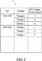
- FIG. 2 illustrates exemplary CPU usage priority level information 17c.
- the CPU usage priority level information 17c indicated in FIG. 2 includes CPU usage priority levels of respective threads of "a copy job” where the printer 14 prints an image read from an original document by the scanner 13 on a recording medium, and CPU usage priority levels of respective threads of "a print job” where the printer 14 prints an image based on print data such as print data received via the communication unit 16 on a recording medium.
- the CPU usage priority level information 17c includes CPU usage priority levels of respective threads of job types other than the copy job and the print job, for example, "a transmitting job” where an image such as the image read from the original document by the scanner 13 is transmitted via the communication unit 16.
- the CPU usage priority level information 17c illustrated in FIG. 2 includes threads A, B, and C as the threads of the copy job.
- the thread A is, for example, a thread for reading the image from the original document by the scanner 13 to generate drawing data corresponding to the read image.
- the thread B is, for example, a thread for writing the drawing data generated by the thread A on a Random Access Memory (RAM) 23 described below.
- the thread C is, for example, a thread for reading the drawing data written on the RAM 23 by the thread B from the RAM 23 to print on a recording medium by the printer 14.
- the threads A, B, and C are configured to have a higher CPU usage priority level as the thread is executed later in the job.
- the CPU usage priority level of the thread C is configured to be higher than the CPU usage priority level of the thread B
- the CPU usage priority level of the thread B is configured to be higher than the CPU usage priority level of the thread A.
- the reason is as follows. For example, when a plurality of jobs are executed in same time period, it takes a long time for a thread to be executed later in the job to be executed, and the result of the process by a thread executed early in the job is excessively accumulated in the RAM 23, thus generating an error of capacity shortage of the RAM 23.
- the copy job may include threads other than the threads A, B, and C.
- the CPU usage priority level information 17c illustrated in FIG. 2 includes threads X, Y, and Z as the threads of the print job.
- the thread X is, for example, a thread for generating the drawing data corresponding to the print data.
- the thread Y is, for example, a thread for writing the drawing data generated by the thread X on the RAM 23 described below.
- the thread Z is, for example, a thread for reading the drawing data written on the RAM 23 by the thread Y from the RAM 23 to print on a recording medium by the printer 14.
- the threads X, Y, and Z are configured to have a higher CPU usage priority level as the thread is executed later in the job.
- the print job may include threads other than the threads X, Y, and Z.
- the control unit 20 includes, for example, a plurality of CPUs 21 as processors, a Read Only Memory (ROM) 22 storing programs and various kinds of data, and the RAM 23 used as a work area of the CPU 21, and Application Specific Integrated Circuits (ASICs) 24, 25, and 26 as hardware for executing specific processes.
- the CPU 21 executes the programs stored in the ROM 22 or the storage unit 17.
- the ASIC 24 is hardware, for example, that executes a process for reading the image from the original document by the scanner 13.
- the ASIC 25 is hardware, for example, that executes a process for rotating the image read by the ASIC 24 to change a direction of the image.
- the ASIC 26 is hardware, for example, that executes a process of a color conversion on the image whose direction is changed by the ASIC 25. The process executed by each of the ASICs 24 to 26 is performed at a high speed compared with a case achieved by the execution of software by the CPU 21.
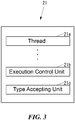
- FIG. 3 illustrates a block diagram of a function achieved by the CPU 21.
- the CPU 21 executes the process execution program 17a stored in the storage unit 17, so as to function as, as illustrated in FIG. 3 , the plurality of threads 21a as process execution units that use the CPU 21 to execute the process, an execution control unit 21b that controls the execution of the process by the thread 21a, and a type accepting unit 21c that accepts a designation of the priority job type.
- the execution control unit 21b writes CPU usage priority level information that includes content identical to the CPU usage priority level information 17c on the RAM 23, and subsequently sets a CPU usage priority level based on the CPU usage priority level information on the RAM 23 by each thread 21a.
- the execution control unit 21b is configured to cause the thread 21a to use the CPU 21 in an order from the high CPU usage priority level. That is, the execution control unit 21b causes a target thread 21a to wait when threads 21a with high CPU usage priority levels compared with the target thread 21a use all the CPUs 21.
- the execution control unit 21b includes any of following settings: a setting (timesharing) where every thread 21a (including the target thread 21a) with the CPU usage priority level identical to the target thread 21a alternately uses the CPUs 21 not used by the threads 21a with the CPU usage priority levels higher than the CPU usage priority level of the target thread 21a in a short time, or a setting (first-come basis) where the threads 21a (including the target thread 21a) with the CPU usage priority levels identical to the target thread 21a use the CPUs 21 not used by the threads 21a with the CPU usage priority levels higher than the CPU usage priority level of the target thread 21a in order.
- the execution control unit 21b causes every thread 21a whose CPU usage priority level is 0 to alternately use the CPUs 21 not used by the threads 21a whose CPU usage priority levels are 1 or more in a short time (timesharing).
- FIG. 4 illustrates the operation of the MFP 10 for setting the priority job type.
- control unit 20 executes the operation illustrated in FIG. 4 .
- the type accepting unit 21c indicates a priority job type setting screen 30 (see FIG. 5 ) for setting the priority job type on the display 12 (Step S101).
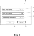
- FIG. 5 illustrates an exemplary priority job type setting screen 30.
- the priority job type setting screen 30 includes a designation region 31 for designating the copy job as the priority job type, a designation region 32 for designating the print job as the priority job type, a designation region 33 for designating the transmitting job as the priority job type, an OK button 34 for accepting the designations by the designation regions 31 to 33, and a cancel button 35 for aborting the acceptance of the designations by the designation regions 31 to 33.
- designation region 31 On the designation region 31, "ON” and “OFF” are switched every time the designation region 31 is pushed. "ON” indicates a state where the copy job is designated as the priority job type. "OFF” indicates a state where the copy job is not designated as the priority job type. While the designation region 31 is described, the same applies to the designation regions 32 and 33.
- the type accepting unit 21c determines whether or not the cancel button 35 is pushed (Step S102).
- the type accepting unit 21c determines that the cancel button 35 is pushed in Step S102, the type accepting unit 21c terminates the operation illustrated in FIG. 4 .
- Step S102 the type accepting unit 21c determines whether or not the OK button 34 is pushed.
- Step S103 the type accepting unit 21c executes the process of Step S102.
- Step S103 the type accepting unit 21c sets the priority job type on the job priority setting information 17b corresponding to the designations by the designation regions 31 to 33 (Step S104), thus terminating the operation illustrated in FIG. 4 .
- FIG. 6 illustrates the operation of the MFP 10 for executing the jobs.
- control unit 20 When a condition for executing the job is satisfied by the instruction via the operation unit 11 and the reception of print data via the communication unit 16, the control unit 20 starts the execution of the job. When any job is not executed, the control unit 20 executes the operation illustrated in FIG. 6 in the start of the execution of a job.
- the execution control unit 21b starts the execution of a target job (Step S131). That is, the execution control unit 21b starts the execution of a plurality of threads 21a in the target job in order.
- the execution control unit 21b sets the CPU usage priority level, set on the CPU usage priority level information on the RAM 23, on the thread 21a in the target job.
- the content of the CPU usage priority level information on the RAM 23 is identical to the content of the CPU usage priority level information 17c.
- Step S132 the execution control unit 21b determines whether or not a condition for an execution of a new job is satisfied.
- Step S133 the execution control unit 21b starts the execution of the new job (Step S133). That is, the execution control unit 21b starts the execution of a plurality of threads 21a in the new job in order.
- the execution control unit 21b sets the CPU usage priority level, set on the CPU usage priority level information on the RAM 23, on the thread 21a in the new job.
- Step S133 the execution control unit 21b determines whether or not a job of the priority job type indicated by the job priority setting information 17b and a job of a type other than the priority job type are both included in the currently executed jobs (Step S134).
- Step S134 the execution control unit 21b changes the CPU usage priority level of the thread 21a of the job of the type other than the priority job type among the currently executed jobs to 0 on the CPU usage priority level information on the RAM 23 (Step S135).
- the execution control unit 21b performs no process in Step S135, thus terminating the process of Step S135.
- the execution control unit 21b also changes the CPU usage priority level of an additionally executed thread 21a to 0 based on the CPU usage priority level information on the RAM 23 after the execution of the process of Step S135 until the execution of the process of Step S139 described below.
- Step S132 determines that the condition for the execution of the new job is not satisfied in Step S132, or the execution control unit 21b determines that at least one of the job of the priority job type and the job of the type other than the priority job type is not included in the currently executed jobs in Step S134, or the process of Step S135 has terminated.
- the execution control unit 21b determines whether or not the execution of any job has terminated (Step S136).
- Step S136 the execution control unit 21b determines whether or not the execution of every job has terminated.
- Step S137 the execution control unit 21b determines whether or not the job of the priority job type indicated by the job priority setting information 17b and the job of the type other than the priority job type are both included in the currently executed jobs (Step S138).
- the execution control unit 21b determines that at least one of the job of the priority job type and the job of the type other than the priority job type is not included in the currently executed jobs in Step S138, the execution control unit 21b returns the CPU usage priority level of the thread 21a of the job of the type other than the priority job type to the original priority level (Step S139). That is, the execution control unit 21b sets the content of the CPU usage priority level information on the RAM 23 identical to the content of the CPU usage priority level information 17c.
- Step S136 When the execution control unit 21b determines that no execution of any job has terminated in Step S136, or the execution control unit 21b determines that the job of the priority job type and the job of the type other than the priority job type are both included in the currently executed jobs in Step S138, or the process of Step S139 has terminated, the execution control unit 21b executes the process of Step S132.
- Step S137 the execution control unit 21b terminates the operation illustrated in FIG. 6 .
- FIG. 7 illustrates an operation of a thread A when ASICs 24 to 26 are used to execute processes.
- the thread A of the copy job executes the operation illustrated in FIG. 7 .
- the thread A determines whether or not the CPU usage priority level of the thread A itself is 0 (Step S161).
- Step S161 When the thread A determines that the CPU usage priority level of the thread A itself is not 0 in Step S161, the thread A instructs the ASICs 24 to 26 to execute a collaborative operation (Step S162), and instructs the ASIC 24 to execute the process (Step S163).
- the ASIC 24 executes a process for reading an image from an original document by the scanner 13 and transmits the image read from the original document to the ASIC 25 by each band of the image.
- the ASIC 25 rotates the image received from the ASIC 24 by each band to change a direction of the image, thus transmitting to the ASIC 26 by each band.
- the ASIC 26 executes a process of a color conversion on the image received from the ASIC 25.
- the RAM 23 is used to achieve the delivery and reception of the data between the ASICs 24 to 26.
- Step S163 the thread A receives a result of the process by the collaborative operation of the ASICs 24 to 26, that is, the image on which the color conversion is performed from the ASIC 26 (Step S164), thus terminating the operation illustrated in FIG. 7 .
- the RAM 23 is used to achieve the delivery and reception of the data between the ASIC 26 and the thread A.
- Step S161 When the thread A determines that the CPU usage priority level of the thread A itself is 0 in Step S161, the thread A instructs the ASICs 24 to 26 to cancel the collaborative operation (Step S165), and instructs the ASIC 24 to execute the process (Step S166).
- the ASIC 24 executes the process for reading the image from the original document by the scanner 13.
- Step S166 the thread A receives a result of the process by the ASIC 24, that is, the image read from the original document by the ASIC 24 from the ASIC 24 (Step S167).
- the RAM 23 is used to achieve the delivery and reception of the data between the ASIC 24 and the thread A.
- the thread A instructs the ASIC 25 to execute the process of the image, received in Step S167, by one band (Step S168).
- the RAM 23 is used to achieve the delivery and reception of the data between the thread A and the ASIC 25.
- the ASIC 25 rotates the image of one band received from the thread A to change the direction of the image.
- Step S168 the thread A receives a result of the process by the ASIC 25, that is, the image of one band whose direction is changed by the ASIC 25 from the ASIC 25 (Step S169).
- the RAM 23 is used to achieve the delivery and reception of the data between the ASIC 25 and the thread A.
- the thread A instructs the ASIC 26 to perform the process of the image by one band received in Step S169 (Step S170).
- the RAM 23 is used to achieve the delivery and reception of the data between the thread A and the ASIC 26.
- the ASIC 26 executes the process of the color conversion on the image of one band received from the thread A.
- the thread A receives a result of the process by the ASIC 26, that is, the image of one band on which the color conversion is performed by the ASIC 26 from the ASIC 26 (Step S171).
- the RAM 23 is used to achieve the delivery and reception of the data between the ASIC 26 and the thread A.
- Step S172 the thread A determines whether or not the process on every band of the image received in Step S167 has terminated.
- Step S172 When the thread A determines that the process on at least a part of the band has not terminated in Step S172, the thread A executes the process of Step S168 on the band on which the process has not terminated.
- Step S172 the thread A terminates the operation illustrated in FIG. 7 .
- the following describes an exemplary case where, as illustrated in FIG. 8 , the print job is executed during the execution of the copy job when the priority job type is the print job.
- a time t1 is a time when the execution of the copy job starts.
- a time t2 is a time when the execution of the print job starts.
- a time t3 is a time when the execution of the print job terminates.
- a time t4 is a time when the execution of the copy job terminates.
- Step S131 As illustrated in FIG. 9 .
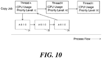
- the collaborative operation of the ASICs 24 to 26 is executed by the processes of Steps S162 to S164 as illustrated in FIG. 10 .
- Step S133 the print job is executed by the process of Step S133 as illustrated in FIG. 11 .
- the print job as the job of the priority job type and the copy job as the job of the type other than the priority job type both exists (YES, in Step S134) as illustrated in FIG. 12 .
- the CPU usage priority levels of the threads 21a that is, the threads A to C of the copy job as the job of the type other than the priority job type are changed to 0 (Step S135).
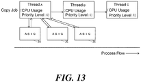
- the processes of Steps S165 to S172 cancel the collaborative operation of the ASICs 24 to 26 to execute the process as illustrated in FIG. 13 .
- Step S139 returns the CPU usage priority level of the thread A to 5 (NO, in Step S161), the processes of Steps S162 to S164 executes the collaborative operation of the ASICs 24 to 26 as illustrated in FIG. 10 .
- the MFP 10 causes the ASICs 24 to 26 to execute the collaborative operation (Step S162), instructs the ASIC 24 to execute the process (Step S163), and receives the result of the process by the collaborative operation from the ASIC 26 (Step S164).
- Step S162 the ASICs 24 to 26 to execute the collaborative operation
- Step S163 instructs the ASIC 24 to execute the process
- Step S164 receives the result of the process by the collaborative operation from the ASIC 26 (Step S164).
- Step S161 When the ASICs 24 to 26 are used to execute the processes, in a case where the CPU usage priority level is 0 (YES, in Step S161), the MFP 10 cancels the collaborative operation of the ASICs 24 to 26 (Step S165), instructs the respective ASICs 24 to 26 to execute the processes (Steps S166, S168, and S170), and receives the results of the processes from the respective ASICs 24 to 26 (Steps S167, S169, and S171).
- the MFP 10 can appropriately use the ASICs 24 to 26 corresponding to the CPU usage priority levels to execute the processes.
- the MFP 10 instructs the ASICs 25 and 26 to execute the process on the image in band units (Steps S168 and S170). This ensures the MFP 10 to reduce the generation of the error of the capacity shortage of the RAM 23 due to the excessive accumulation of the results of the processes by the ASICs 24 to 26 in the RAM 23.
- the MFP 10 can execute the processes of the image in a small unit (in band units in this case) compared with a unit of the image on which any of the plurality of hardware units (the ASICs 24 to 26 in this case) is instructed to execute a process in a case where the processor usage priority level exceeds the specific priority level (0 in this case).
- Step S135 the MFP 10 changes the CPU usage priority level to 0 as the lowest priority level in a settable range.
- This configuration causes the MFP 10 to instruct the respective ASICs 24 to 26 to execute the processes and to receive the results of the processes from the respective ASICs 24 to 26 only when a speed to instruct the ASICs 24 to 26 to execute the processes and a speed to receive the results of the processes by the ASICs 24 to 26 are lowest. This ensures the MFP 10 to reduce an unnecessarily decrease of the speed of the execution of the processes.
- the MFP 10 decreases the CPU usage priority level of the job of the type other than the priority job type (Step S135). This ensures the MFP 10 to execute a job of specific type with priority.
- Step S135 the MFP 10 decreases the CPU usage priority level to the lowest priority level in the settable range, that is, 0. Accordingly, the MFP 10 decreases the execution speed of the job of the type other than the priority job type to lowest, thus executing the job of the priority job type with precise priority.
- the MFP 10 accepts the designation of the job type to be executed with priority (Step S104), thus executing a job of a type desired by a user with priority.
- Step S138 the MFP 10 returns the CPU usage priority level of the job whose CPU usage priority level has been decreased (Step S139). This ensures the MFP 10 to reduce an unnecessarily delay of the termination time of the execution of the job of the type other than the priority job type.
- the MFP 10 includes the plurality of the CPUs 21 as processors of the invention. Accordingly, the MFP 10 can increase the number of simultaneously processable threads 21a, thus increasing the speed of the execution of the processes as the entire MFP 10.
- the MFP 10 may include a multi-core processor with a plurality of CPU cores as the processor of the invention, or may include only one CPU 21 as the processor of the invention.
- the electronic device of the invention is the MFP in the embodiment, the electronic device may be an image forming apparatus, for example, a printer-only machine, a scanner-only machine, a copy-only machine, other than the MFP, or may be an electronic device, for example, a PC other than the image forming apparatus.
Landscapes
- Engineering & Computer Science (AREA)
- Theoretical Computer Science (AREA)
- Physics & Mathematics (AREA)
- General Engineering & Computer Science (AREA)
- General Physics & Mathematics (AREA)
- Software Systems (AREA)
- Human Computer Interaction (AREA)
- Facsimiles In General (AREA)
- Accessory Devices And Overall Control Thereof (AREA)
Abstract
Description
- Unless otherwise indicated herein, the description in this section is not prior art to the claims in this application and is not admitted to be prior art by inclusion in this section.
- There has been known a typical electronic device that includes a processor that performs a task, and a peripheral hardware connected to the processor to execute processes. The typical electronic device reduces a priority level of a processor usage by the task that has caused the peripheral hardware to execute the processes.
- An electronic device according to one aspect of the invention executes a plurality of types of a job. The electronic device includes a Central Processing Unit (CPU), and a storage unit that stores a process execution program. The CPU executes the process execution program, and functions as a plurality of threads and an execution control unit. The plurality of threads use the CPU to execute a process. The execution control unit controls executing of the process by the plurality of threads. The execution control unit sets a CPU usage priority level for each of the plurality of threads. The execution control unit changes the CPU usage priority level of the job of a type other than a specific type to a priority level that is equal to or less than a specific priority level, when the job of the specific type and the job of the type other than the specific type are simultaneously executed.
- According to a further aspect, the present disclosure relates to a method for executing a plurality of types of a job by means of an electronic device, said electronic device comprising a Central Processing Unit CPU, and a storage unit that is configured to store a process execution program. According to this method, the process execution program stored by the storage unit is executed by the CPU such that the CPU functions as a plurality of threads that use the CPU to execute a process; and/or as an execution control unit that controls executing of the process by the plurality of threads. Moreover, a CPU usage priority level for each of the plurality of threads is set by the by the execution control unit, and the CPU usage priority level of the job of a type other than a specific type is changed by the execution control unit to a priority level that is equal to or less than a specific priority level when the job of the specific type and the job of the type other than the specific type are simultaneously executed.
- These as well as other aspects, advantages, and alternatives will become apparent to those of ordinary skill in the art by reading the following detailed description with reference where appropriate to the accompanying drawings. Further, it should be understood that the description provided in this summary section and elsewhere in this document is intended to illustrate the claimed subject matter by way of example and not by way of limitation.
-
- FIG. 1
- illustrates a block diagram of an MFP according to one embodiment of the invention;
- FIG. 2
- illustrates exemplary CPU usage priority level information according to the one embodiment;
- FIG. 3
- illustrates a block diagram of a function achieved by a CPU according to the one embodiment;
- FIG. 4
- illustrates an operation of an MFP according to the one embodiment for setting a priority job type;
- FIG. 5
- illustrates an exemplary priority job type setting screen indicated in the operation illustrated in
FIG. 4 ; - FIG. 6
- illustrates an operation of the MFP according to the one embodiment for executing jobs;
- FIG. 7
- illustrates an operation of a thread when ASICs according to the one embodiment are used to execute processes;
- FIG. 8
- illustrates an example when a print job is executed while a copy job is executed in the MFP according to the one embodiment;
- FIG. 9
- illustrates exemplary threads according to the one embodiment when only the copy job is executed;
- FIG. 10
- illustrates a relation between the threads and the ASICs in the state illustrated in
FIG. 9 ; - FIG. 11
- illustrates exemplary threads according to the one embodiment before a CPU usage priority level of the copy job is changed when the copy job and the print job are executed;
- FIG. 12
- illustrates exemplary threads according to the one embodiment after the CPU usage priority level of the copy job is changed when the copy job and the print job are executed; and
- FIG. 13
- illustrates a relation between the threads and the ASICs in the state illustrated in
FIG. 12 . - Example apparatuses are described herein. Other example embodiments or features may further be utilized, and other changes may be made, without departing from the spirit or scope of the subject matter presented herein. In the following detailed description, reference is made to the accompanying drawings, which form a part thereof.
- The example embodiments described herein are not meant to be limiting. It will be readily understood that the aspects of the present invention, as generally described herein, and illustrated in the drawings, can be arranged, substituted, combined, separated, and designed in a wide variety of different configurations, all of which are explicitly contemplated herein.
- The following describes one embodiment of the invention by referring to the drawings.
- First, a description will be given of a configuration of a Multifunction Peripheral (MFP) as an electronic device according to the embodiment.
-
FIG. 1 illustrates a block diagram of anMFP 10 according to one embodiment of the invention. - As illustrated in
FIG. 1 , the MFP 10 includes an operation unit 11, adisplay 12, ascanner 13, aprinter 14, afax communication unit 15, acommunication unit 16, astorage unit 17, and acontrol unit 20. The operation unit 11 is an input device such as buttons for inputting various kinds of operations. Thedisplay 12 is a display device such as a Liquid Crystal Display (LCD) for displaying various kinds of information. Thescanner 13 is a reading device for reading an image from an original document. Theprinter 14 is a print device for printing the image on a recording medium such as a paper sheet. Thefax communication unit 15 is a facsimile device for carrying out fax communication with an external fax device (not illustrated) via a communication line such as a dial-up line. Thecommunication unit 16 is a communication device for communicating with external devices via a network such as Internet and a Local Area Network (LAN) or communicating directly by a wired communication or a wireless communication without via the network. Thestorage unit 17 is a non-volatile storage device such as a semiconductor memory and a Hard Disk Drive (HDD) for storing various kinds of information. Thecontrol unit 20 controls overall operation of theMFP 10. - The
storage unit 17 stores aprocess execution program 17a for executing processes in theMFP 10. Theprocess execution program 17a may be installed in theMFP 10 at the production stage of theMFP 10, may be additionally installed in theMFP 10 from an external storage medium such as a SD card or a Universal Serial Bus (USB) memory, or may be additionally installed in theMFP 10 from the network. - The
storage unit 17 is configured to store jobpriority setting information 17b that indicates a setting of a job type preferentially executed by theMFP 10. Hereinafter, the job type preferentially executed by theMFP 10 is referred to as "a priority job type." In default, the jobpriority setting information 17b does not indicate the priority job type. - The
storage unit 17 stores a CPU usage priority level as CPU usagepriority level information 17c. The CPU usage priority level is a processor usage priority level as a priority level of the use of a Central Processing Unit (CPU) 21 described below by athread 21a (seeFIG. 3 ) described below. The CPU usagepriority level information 17c is indicated by each type of thethread 21a set by each job type. Here, the CPU usage priority level is an integer of 0 or more, and high as the value increases. -
FIG. 2 illustrates exemplary CPU usagepriority level information 17c. - The CPU usage
priority level information 17c indicated inFIG. 2 includes CPU usage priority levels of respective threads of "a copy job" where theprinter 14 prints an image read from an original document by thescanner 13 on a recording medium, and CPU usage priority levels of respective threads of "a print job" where theprinter 14 prints an image based on print data such as print data received via thecommunication unit 16 on a recording medium. However, in practice, the CPU usagepriority level information 17c includes CPU usage priority levels of respective threads of job types other than the copy job and the print job, for example, "a transmitting job" where an image such as the image read from the original document by thescanner 13 is transmitted via thecommunication unit 16. - The CPU usage
priority level information 17c illustrated inFIG. 2 includes threads A, B, and C as the threads of the copy job. The thread A is, for example, a thread for reading the image from the original document by thescanner 13 to generate drawing data corresponding to the read image. The thread B is, for example, a thread for writing the drawing data generated by the thread A on a Random Access Memory (RAM) 23 described below. The thread C is, for example, a thread for reading the drawing data written on theRAM 23 by the thread B from theRAM 23 to print on a recording medium by theprinter 14. The threads A, B, and C are configured to have a higher CPU usage priority level as the thread is executed later in the job. That is, the CPU usage priority level of the thread C is configured to be higher than the CPU usage priority level of the thread B, and the CPU usage priority level of the thread B is configured to be higher than the CPU usage priority level of the thread A. The reason is as follows. For example, when a plurality of jobs are executed in same time period, it takes a long time for a thread to be executed later in the job to be executed, and the result of the process by a thread executed early in the job is excessively accumulated in theRAM 23, thus generating an error of capacity shortage of theRAM 23. The copy job may include threads other than the threads A, B, and C. - The CPU usage
priority level information 17c illustrated inFIG. 2 includes threads X, Y, and Z as the threads of the print job. The thread X is, for example, a thread for generating the drawing data corresponding to the print data. The thread Y is, for example, a thread for writing the drawing data generated by the thread X on theRAM 23 described below. The thread Z is, for example, a thread for reading the drawing data written on theRAM 23 by the thread Y from theRAM 23 to print on a recording medium by theprinter 14. The threads X, Y, and Z are configured to have a higher CPU usage priority level as the thread is executed later in the job. That is, the CPU usage priority level of the thread Z is configured to be higher than the CPU usage priority level of the thread Y, and the CPU usage priority level of the thread Y is configured to be higher than the CPU usage priority level of the thread X. The reason is similar to the above-described reason for the threads A, B, and C of the copy job. The print job may include threads other than the threads X, Y, and Z. - As illustrated in
FIG. 1 , thecontrol unit 20 includes, for example, a plurality ofCPUs 21 as processors, a Read Only Memory (ROM) 22 storing programs and various kinds of data, and theRAM 23 used as a work area of theCPU 21, and Application Specific Integrated Circuits (ASICs) 24, 25, and 26 as hardware for executing specific processes. TheCPU 21 executes the programs stored in theROM 22 or thestorage unit 17. - The
ASIC 24 is hardware, for example, that executes a process for reading the image from the original document by thescanner 13. TheASIC 25 is hardware, for example, that executes a process for rotating the image read by theASIC 24 to change a direction of the image. TheASIC 26 is hardware, for example, that executes a process of a color conversion on the image whose direction is changed by theASIC 25. The process executed by each of theASICs 24 to 26 is performed at a high speed compared with a case achieved by the execution of software by theCPU 21. -
FIG. 3 illustrates a block diagram of a function achieved by theCPU 21. - The
CPU 21 executes theprocess execution program 17a stored in thestorage unit 17, so as to function as, as illustrated inFIG. 3 , the plurality ofthreads 21a as process execution units that use theCPU 21 to execute the process, anexecution control unit 21b that controls the execution of the process by thethread 21a, and atype accepting unit 21c that accepts a designation of the priority job type. - The
execution control unit 21b writes CPU usage priority level information that includes content identical to the CPU usagepriority level information 17c on theRAM 23, and subsequently sets a CPU usage priority level based on the CPU usage priority level information on theRAM 23 by eachthread 21a. Theexecution control unit 21b is configured to cause thethread 21a to use theCPU 21 in an order from the high CPU usage priority level. That is, theexecution control unit 21b causes atarget thread 21a to wait whenthreads 21a with high CPU usage priority levels compared with thetarget thread 21a use all theCPUs 21. When the number of theCPUs 21 is greater than the number of thethreads 21a whose CPU usage priority levels are high compared with thetarget thread 21a, and the number ofCPUs 21 is smaller than the number of thethreads 21a (including thetarget thread 21a) whose CPU usage priority levels are equal to or more than the CPU usage priority level of thetarget thread 21a, theexecution control unit 21b includes any of following settings: a setting (timesharing) where everythread 21a (including thetarget thread 21a) with the CPU usage priority level identical to thetarget thread 21a alternately uses theCPUs 21 not used by thethreads 21a with the CPU usage priority levels higher than the CPU usage priority level of thetarget thread 21a in a short time, or a setting (first-come basis) where thethreads 21a (including thetarget thread 21a) with the CPU usage priority levels identical to thetarget thread 21a use theCPUs 21 not used by thethreads 21a with the CPU usage priority levels higher than the CPU usage priority level of thetarget thread 21a in order. However, when the CPU usage priority level of thetarget thread 21a is 0, and the number of theCPUs 21 is greater than the number of thethreads 21a whose CPU usage priority levels are 1 or more and the number of theCPUs 21 is smaller than the number of thethreads 21a whose CPU usage priority levels are 0 or more, theexecution control unit 21b causes everythread 21a whose CPU usage priority level is 0 to alternately use theCPUs 21 not used by thethreads 21a whose CPU usage priority levels are 1 or more in a short time (timesharing). - Next, the operation of the
MFP 10 will be described. - First, the operation of the
MFP 10 for setting the priority job type will be described. -
FIG. 4 illustrates the operation of theMFP 10 for setting the priority job type. - When a start of setting the priority job type is instructed via the operation unit 11, the
control unit 20 executes the operation illustrated inFIG. 4 . - As illustrated in
FIG. 4 , thetype accepting unit 21c indicates a priority job type setting screen 30 (seeFIG. 5 ) for setting the priority job type on the display 12 (Step S101). -
FIG. 5 illustrates an exemplary priority jobtype setting screen 30. - As illustrated in
FIG. 5 , the priority jobtype setting screen 30 includes adesignation region 31 for designating the copy job as the priority job type, adesignation region 32 for designating the print job as the priority job type, adesignation region 33 for designating the transmitting job as the priority job type, anOK button 34 for accepting the designations by thedesignation regions 31 to 33, and a cancelbutton 35 for aborting the acceptance of the designations by thedesignation regions 31 to 33. - On the
designation region 31, "ON" and "OFF" are switched every time thedesignation region 31 is pushed. "ON" indicates a state where the copy job is designated as the priority job type. "OFF" indicates a state where the copy job is not designated as the priority job type. While thedesignation region 31 is described, the same applies to thedesignation regions - As illustrated in
FIG. 4 , thetype accepting unit 21c determines whether or not the cancelbutton 35 is pushed (Step S102). - When the
type accepting unit 21c determines that the cancelbutton 35 is pushed in Step S102, thetype accepting unit 21c terminates the operation illustrated inFIG. 4 . - When the
type accepting unit 21c determines that the cancelbutton 35 is not pushed in Step S102, thetype accepting unit 21c determines whether or not theOK button 34 is pushed (Step S103). - When the
type accepting unit 21c determines that theOK button 34 is not pushed in Step S103, thetype accepting unit 21c executes the process of Step S102. - When the
type accepting unit 21c determines that theOK button 34 is pushed in Step S103, thetype accepting unit 21c sets the priority job type on the jobpriority setting information 17b corresponding to the designations by thedesignation regions 31 to 33 (Step S104), thus terminating the operation illustrated inFIG. 4 . - Next, the operation of the
MFP 10 for executing jobs will be described. -
FIG. 6 illustrates the operation of theMFP 10 for executing the jobs. - When a condition for executing the job is satisfied by the instruction via the operation unit 11 and the reception of print data via the
communication unit 16, thecontrol unit 20 starts the execution of the job. When any job is not executed, thecontrol unit 20 executes the operation illustrated inFIG. 6 in the start of the execution of a job. - As illustrated in
FIG. 6 , theexecution control unit 21b starts the execution of a target job (Step S131). That is, theexecution control unit 21b starts the execution of a plurality ofthreads 21a in the target job in order. Here, when theexecution control unit 21b executes thethreads 21a in the target job, as described above, theexecution control unit 21b sets the CPU usage priority level, set on the CPU usage priority level information on theRAM 23, on thethread 21a in the target job. At the point of the process of Step S131, the content of the CPU usage priority level information on theRAM 23 is identical to the content of the CPU usagepriority level information 17c. - After the process of Step S131, the
execution control unit 21b determines whether or not a condition for an execution of a new job is satisfied (Step S132). - When the
execution control unit 21b determines that the condition for the execution of the new job is satisfied in Step S132, theexecution control unit 21b starts the execution of the new job (Step S133). That is, theexecution control unit 21b starts the execution of a plurality ofthreads 21a in the new job in order. Here, when theexecution control unit 21b executes thethreads 21a in the new job, as described above, theexecution control unit 21b sets the CPU usage priority level, set on the CPU usage priority level information on theRAM 23, on thethread 21a in the new job. - After the process of Step S133, the
execution control unit 21b determines whether or not a job of the priority job type indicated by the jobpriority setting information 17b and a job of a type other than the priority job type are both included in the currently executed jobs (Step S134). - When the
execution control unit 21b determines that the job of the priority job type and the job of the type other than the priority job type are both included in the currently executed jobs in Step S134, theexecution control unit 21b changes the CPU usage priority level of thethread 21a of the job of the type other than the priority job type among the currently executed jobs to 0 on the CPU usage priority level information on the RAM 23 (Step S135). Here, when a job whose CPU usage priority level is required to be changed to 0 is not in execution, theexecution control unit 21b performs no process in Step S135, thus terminating the process of Step S135. Relating to the job of the type other than the priority job type among the currently executed jobs, theexecution control unit 21b also changes the CPU usage priority level of an additionally executedthread 21a to 0 based on the CPU usage priority level information on theRAM 23 after the execution of the process of Step S135 until the execution of the process of Step S139 described below. - When the
execution control unit 21b determines that the condition for the execution of the new job is not satisfied in Step S132, or theexecution control unit 21b determines that at least one of the job of the priority job type and the job of the type other than the priority job type is not included in the currently executed jobs in Step S134, or the process of Step S135 has terminated, theexecution control unit 21b determines whether or not the execution of any job has terminated (Step S136). - When the
execution control unit 21b determines that the execution of any job has terminated in Step S136, theexecution control unit 21b determines whether or not the execution of every job has terminated (Step S137). - When the
execution control unit 21b determines that the execution of any job has not terminated in Step S137, theexecution control unit 21b determines whether or not the job of the priority job type indicated by the jobpriority setting information 17b and the job of the type other than the priority job type are both included in the currently executed jobs (Step S138). - When the
execution control unit 21b determines that at least one of the job of the priority job type and the job of the type other than the priority job type is not included in the currently executed jobs in Step S138, theexecution control unit 21b returns the CPU usage priority level of thethread 21a of the job of the type other than the priority job type to the original priority level (Step S139). That is, theexecution control unit 21b sets the content of the CPU usage priority level information on theRAM 23 identical to the content of the CPU usagepriority level information 17c. - When the
execution control unit 21b determines that no execution of any job has terminated in Step S136, or theexecution control unit 21b determines that the job of the priority job type and the job of the type other than the priority job type are both included in the currently executed jobs in Step S138, or the process of Step S139 has terminated, theexecution control unit 21b executes the process of Step S132. - When the
execution control unit 21b determines that the execution of every job has terminated in Step S137, theexecution control unit 21b terminates the operation illustrated inFIG. 6 . -
FIG. 7 illustrates an operation of a thread A whenASICs 24 to 26 are used to execute processes. - When the
ASICs 24 to 26 are used to execute the processes, the thread A of the copy job executes the operation illustrated inFIG. 7 . - As illustrated in
FIG. 7 , the thread A determines whether or not the CPU usage priority level of the thread A itself is 0 (Step S161). - When the thread A determines that the CPU usage priority level of the thread A itself is not 0 in Step S161, the thread A instructs the ASICs 24 to 26 to execute a collaborative operation (Step S162), and instructs the
ASIC 24 to execute the process (Step S163). - Accordingly, the
ASIC 24 executes a process for reading an image from an original document by thescanner 13 and transmits the image read from the original document to theASIC 25 by each band of the image. Next, theASIC 25 rotates the image received from theASIC 24 by each band to change a direction of the image, thus transmitting to theASIC 26 by each band. Next, theASIC 26 executes a process of a color conversion on the image received from theASIC 25. TheRAM 23 is used to achieve the delivery and reception of the data between the ASICs 24 to 26. - After the process of Step S163, the thread A receives a result of the process by the collaborative operation of the
ASICs 24 to 26, that is, the image on which the color conversion is performed from the ASIC 26 (Step S164), thus terminating the operation illustrated inFIG. 7 . TheRAM 23 is used to achieve the delivery and reception of the data between theASIC 26 and the thread A. - When the thread A determines that the CPU usage priority level of the thread A itself is 0 in Step S161, the thread A instructs the ASICs 24 to 26 to cancel the collaborative operation (Step S165), and instructs the
ASIC 24 to execute the process (Step S166). - Accordingly, the
ASIC 24 executes the process for reading the image from the original document by thescanner 13. - After the process of Step S166, the thread A receives a result of the process by the
ASIC 24, that is, the image read from the original document by theASIC 24 from the ASIC 24 (Step S167). TheRAM 23 is used to achieve the delivery and reception of the data between theASIC 24 and the thread A. - Next, the thread A instructs the
ASIC 25 to execute the process of the image, received in Step S167, by one band (Step S168). TheRAM 23 is used to achieve the delivery and reception of the data between the thread A and theASIC 25. - Accordingly, the
ASIC 25 rotates the image of one band received from the thread A to change the direction of the image. - After the process of Step S168, the thread A receives a result of the process by the
ASIC 25, that is, the image of one band whose direction is changed by theASIC 25 from the ASIC 25 (Step S169). TheRAM 23 is used to achieve the delivery and reception of the data between theASIC 25 and the thread A. - Next, the thread A instructs the
ASIC 26 to perform the process of the image by one band received in Step S169 (Step S170). TheRAM 23 is used to achieve the delivery and reception of the data between the thread A and theASIC 26. - Accordingly, the
ASIC 26 executes the process of the color conversion on the image of one band received from the thread A. - After the process of Step S170, the thread A receives a result of the process by the
ASIC 26, that is, the image of one band on which the color conversion is performed by theASIC 26 from the ASIC 26 (Step S171). TheRAM 23 is used to achieve the delivery and reception of the data between theASIC 26 and the thread A. - Next, the thread A determines whether or not the process on every band of the image received in Step S167 has terminated (Step S172).
- When the thread A determines that the process on at least a part of the band has not terminated in Step S172, the thread A executes the process of Step S168 on the band on which the process has not terminated.
- When the thread A determines that the process on every band has terminated in Step S172, the thread A terminates the operation illustrated in
FIG. 7 . - The following describes an exemplary case where, as illustrated in
FIG. 8 , the print job is executed during the execution of the copy job when the priority job type is the print job. - In
FIG. 8 , a time t1 is a time when the execution of the copy job starts. A time t2 is a time when the execution of the print job starts. A time t3 is a time when the execution of the print job terminates. A time t4 is a time when the execution of the copy job terminates. - First, from the time t1 to the time t2, only the copy job is executed by the process of Step S131 as illustrated in
FIG. 9 . At this time, since the CPU usage priority level of the thread A is 5 (NO, in Step S161), the collaborative operation of theASICs 24 to 26 is executed by the processes of Steps S162 to S164 as illustrated inFIG. 10 . - Next, from the time t2 to the time t3 illustrated in
FIG. 8 , first, the print job is executed by the process of Step S133 as illustrated inFIG. 11 . Then, since the print job as the job of the priority job type and the copy job as the job of the type other than the priority job type both exists (YES, in Step S134), as illustrated inFIG. 12 , the CPU usage priority levels of thethreads 21a, that is, the threads A to C of the copy job as the job of the type other than the priority job type are changed to 0 (Step S135). At this time, since the CPU usage priority level of the thread A is 0 (YES, in Step S161), the processes of Steps S165 to S172 cancel the collaborative operation of theASICs 24 to 26 to execute the process as illustrated inFIG. 13 . - Next, from the time t3 to the time t4, again, only the copy job is executed as illustrated in
FIG. 9 . At this time, since the process of Step S139 returns the CPU usage priority level of the thread A to 5 (NO, in Step S161), the processes of Steps S162 to S164 executes the collaborative operation of theASICs 24 to 26 as illustrated inFIG. 10 . - As described above, when the ASICs 24 to 26 are used to execute the processes, in a case where the CPU usage priority level exceeds 0 (NO, in Step S161), the
MFP 10 causes theASICs 24 to 26 to execute the collaborative operation (Step S162), instructs theASIC 24 to execute the process (Step S163), and receives the result of the process by the collaborative operation from the ASIC 26 (Step S164). This ensures theMFP 10 to receive the result of a high speed process by the collaborative operation of theASICs 24 to 26 at high speed after the instruction of the execution of the process to theASIC 24. - When the
ASICs 24 to 26 are used to execute the processes, in a case where the CPU usage priority level is 0 (YES, in Step S161), theMFP 10 cancels the collaborative operation of theASICs 24 to 26 (Step S165), instructs therespective ASICs 24 to 26 to execute the processes (Steps S166, S168, and S170), and receives the results of the processes from therespective ASICs 24 to 26 (Steps S167, S169, and S171). This ensures theMFP 10 to reduce the generation of the error of the capacity shortage of theRAM 23 due to the excessive accumulation of the results of the processes by theASICs 24 to 26 in theRAM 23, even if theMFP 10 cannot receive the results of the processes by theASICs 24 to 26 at high speed because of low CPU usage priority levels. - Accordingly, the
MFP 10 can appropriately use theASICs 24 to 26 corresponding to the CPU usage priority levels to execute the processes. - When the
ASICs 24 to 26 are used to execute the processes, in a case where the CPU usage priority level is 0, theMFP 10 instructs the ASICs 25 and 26 to execute the process on the image in band units (Steps S168 and S170). This ensures theMFP 10 to reduce the generation of the error of the capacity shortage of theRAM 23 due to the excessive accumulation of the results of the processes by theASICs 24 to 26 in theRAM 23. Thus, theMFP 10 can execute the processes of the image in a small unit (in band units in this case) compared with a unit of the image on which any of the plurality of hardware units (the ASICs 24 to 26 in this case) is instructed to execute a process in a case where the processor usage priority level exceeds the specific priority level (0 in this case). - In Step S135, the
MFP 10 changes the CPU usage priority level to 0 as the lowest priority level in a settable range. This configuration causes theMFP 10 to instruct therespective ASICs 24 to 26 to execute the processes and to receive the results of the processes from therespective ASICs 24 to 26 only when a speed to instruct the ASICs 24 to 26 to execute the processes and a speed to receive the results of the processes by theASICs 24 to 26 are lowest. This ensures theMFP 10 to reduce an unnecessarily decrease of the speed of the execution of the processes. - When the job of the priority job type and the job of the type other than the priority job type are simultaneously executed (YES, in Step S134), the
MFP 10 decreases the CPU usage priority level of the job of the type other than the priority job type (Step S135). This ensures theMFP 10 to execute a job of specific type with priority. - In Step S135, the
MFP 10 decreases the CPU usage priority level to the lowest priority level in the settable range, that is, 0. Accordingly, theMFP 10 decreases the execution speed of the job of the type other than the priority job type to lowest, thus executing the job of the priority job type with precise priority. - The
MFP 10 accepts the designation of the job type to be executed with priority (Step S104), thus executing a job of a type desired by a user with priority. - When the job of the priority job type and the job of the type other than the priority job type are no longer executed simultaneously (NO, in Step S138), the
MFP 10 returns the CPU usage priority level of the job whose CPU usage priority level has been decreased (Step S139). This ensures theMFP 10 to reduce an unnecessarily delay of the termination time of the execution of the job of the type other than the priority job type. - In the embodiment, the
MFP 10 includes the plurality of theCPUs 21 as processors of the invention. Accordingly, theMFP 10 can increase the number of simultaneouslyprocessable threads 21a, thus increasing the speed of the execution of the processes as theentire MFP 10. TheMFP 10 may include a multi-core processor with a plurality of CPU cores as the processor of the invention, or may include only oneCPU 21 as the processor of the invention. - While the electronic device of the invention is the MFP in the embodiment, the electronic device may be an image forming apparatus, for example, a printer-only machine, a scanner-only machine, a copy-only machine, other than the MFP, or may be an electronic device, for example, a PC other than the image forming apparatus.
- While various aspects and embodiments have been disclosed herein, other aspects and embodiments will be apparent to those skilled in the art. The various aspects and embodiments disclosed herein are for purposes of illustration and are not intended to be limiting, with the true scope and spirit being indicated by the following claims.
Claims (14)
- An electronic device (10) that executes a plurality of types of a job, comprising:- a Central Processing Unit CPU (21); and- a storage unit (17) that is configured to store a process execution program (17a),wherein the CPU (21) is configured to execute the process execution program (17a) such as to function:- as a plurality of threads (21a) that use the CPU (21) to execute a process; and/or- as an execution control unit (21b) that controls executing of the process by the plurality of threads (21a),characterized in that
the execution control unit (21b) is configured:(i) to set a CPU usage priority level for each of the plurality of threads (21a), and(ii) to change the CPU usage priority level of the job of a type other than a specific type to a priority level that is equal to or less than a specific priority level when the job of the specific type and the job of the type other than the specific type are simultaneously executed. - The electronic device (10) according to claim 1,
wherein the specific priority level is a lowest priority level in a settable range. - The electronic device (10) according to claim 1 or 2,
wherein the CPU (21) is configured to execute the process execution program (17a) to further function as a type accepting unit (21c) that accepts a designation of the specific type. - The electronic device (10) according to one of claims 1 to 3,
wherein the execution control unit (21b) is configured to return the CPU usage priority level of the job whose CPU usage priority level has been changed to the priority level before changing, when the job of the specific type and the job of the type other than the specific type are no longer executed simultaneously. - A method for executing a plurality of types of a job by means of an electronic device (10), said electronic device (10) comprising a Central Processing Unit CPU (21), and a storage unit (17) that is configured to store a process execution program (17a), wherein the method comprises the following steps:- the process execution program (17a) stored by the storage unit (17) is executed by the CPU (21) such that the CPU (21) functions as a plurality of threads (21a) that use the CPU (21) to execute a process; and/or as an execution control unit (21b) that controls executing of the process by the plurality of threads (21a),characterized by the following steps executed by the execution control unit (21b):(i) a CPU usage priority level for each of the plurality of threads (21a) is set, and(ii) the CPU usage priority level of the job of a type other than a specific type is changed to a priority level that is equal to or less than a specific priority level when the job of the specific type and the job of the type other than the specific type are simultaneously executed.
- The method according to claim 5,
wherein the specific priority level is a lowest priority level in a settable range. - The method according to claim 5 or 6,
wherein the CPU (21) executes the process execution program (17a) to further function as a type accepting unit (21c) that accepts a designation of the specific type. - The method according to one of claims 5 to 7,
wherein the execution control unit (21b) returns the CPU usage priority level of the job whose CPU usage priority level has been changed to the priority level before changing, when the job of the specific type and the job of the type other than the specific type are no longer executed simultaneously. - An electronic device (10), comprising:- a Central Processing Unit CPU (21);- a storage unit that is configured to store a process execution program, and- a plurality of Application Specific Integrated Circuits ASICs (24, 25; 26) that are configured to execute a specific process,wherein the CPU (21) is configured to execute the process execution program as such as to function:- as a plurality of threads (21a) that use the CPU to execute a process; and/or- as an execution control unit (21b) that controls executing of the process by the plurality of threads (21a),characterized
in that the execution control unit (21b) is configured to set a CPU usage priority level for each of the plurality of threads (21a),
in that, when the CPU usage priority level exceeds a specific priority level in a case where the plurality of ASICs (24, 25; 26) are used to execute the process, the plurality of threads (21a) is configured:i) to cause the plurality of ASICs (24, 25; 26) to execute a collaborative operation,ii) to instruct any of the plurality of ASICs (24, 25; 26) to execute the process, andiii) to receive a result of the process by the collaborative operation from any of the plurality of ASICs (24,25;26), andin that, when the CPU usage priority level is equal to or less than the specific priority level in a case where the plurality of ASICs (24, 25; 26) are used to execute the process, the plurality of threads (21a) is configured:i) to cancel the collaborative operation,ii) to instruct each of the plurality of ASICs (24, 25; 26) to execute the process, andiii) to receive the result of the process from each of the plurality of ASICs (24,25;26). - The electronic device (10) according to claim 9,
wherein the plurality of ASICs (24, 25; 26) is configured to execute a process of an image;
the plurality of threads (21a), when the CPU usage priority level is equal to or less than the specific priority level in a case where the plurality of ASICs (24,25;26) are used to execute the process, is configured to instruct at least one of the plurality of ASICs (24, 25; 26) to execute the process of the image in a small unit compared with a unit of the image on which any of the plurality of ASICs (24, 25; 26) is instructed to execute the process in a case where the CPU usage priority level exceeds the specific priority level. - The electronic device (10) according to claim 9 or 10,
wherein the specific priority level is a lowest priority level in a settable range. - The electronic device (10) according to one of claims 9 to 11,
wherein the electronic device (10) is configured to execute a plurality of types of a job, and
the execution control unit (21b) is configured to change the CPU usage priority level of the job of a type other than a specific type to a priority level that is equal to or less than the specific priority level, when the job of the specific type and the job of the type other than the specific type are simultaneously executed. - The electronic device (10) according to claim 12,
wherein the CPU (21) is configured to execute the process execution program (17a) to further function as a type accepting unit (21c) that accepts a designation of the specific type. - The electronic device (10) according to claim 12 or 13,
wherein the execution control unit (21b), when the job of the specific type and the job of the type other than the specific type are no longer executed simultaneously, is configured to return the CPU usage priority level of the job whose CPU usage priority level has been changed to the priority level before changing.
Applications Claiming Priority (2)
| Application Number | Priority Date | Filing Date | Title |
|---|---|---|---|
| JP2016107381A JP6528952B2 (en) | 2016-05-30 | 2016-05-30 | Electronic device and processing execution program |
| JP2016107378A JP6528951B2 (en) | 2016-05-30 | 2016-05-30 | Electronic device and processing execution program |
Publications (2)
| Publication Number | Publication Date |
|---|---|
| EP3252601A1 true EP3252601A1 (en) | 2017-12-06 |
| EP3252601B1 EP3252601B1 (en) | 2021-10-20 |
Family
ID=58778961
Family Applications (1)
| Application Number | Title | Priority Date | Filing Date |
|---|---|---|---|
| EP17173045.0A Not-in-force EP3252601B1 (en) | 2016-05-30 | 2017-05-26 | Apparatus and method for changing priority of a job |
Country Status (3)
| Country | Link |
|---|---|
| US (2) | US10534641B2 (en) |
| EP (1) | EP3252601B1 (en) |
| CN (1) | CN107450970B (en) |
Families Citing this family (2)
| Publication number | Priority date | Publication date | Assignee | Title |
|---|---|---|---|---|
| US12619468B2 (en) | 2022-12-16 | 2026-05-05 | Nxp Usa, Inc. | Hardware integrated, priority-encoded domains |
| US12613818B2 (en) * | 2023-09-27 | 2026-04-28 | Nxp Usa, Inc. | Hardware integrated quality of service (HiQoS) |
Citations (4)
| Publication number | Priority date | Publication date | Assignee | Title |
|---|---|---|---|---|
| US6584488B1 (en) * | 1999-04-12 | 2003-06-24 | International Business Machines Corporation | Controlling allocation of system resources with an enhanced priority calculation |
| EP1862898A2 (en) * | 2006-05-29 | 2007-12-05 | Matsushita Electric Industrial Co., Ltd. | Information processing device, information processing method, and computer-readable information recording medium recorded with information processing program |
| US7559061B1 (en) * | 2008-03-16 | 2009-07-07 | International Business Machines Corporation | Simultaneous multi-threading control monitor |
| US20140373021A1 (en) * | 2013-06-14 | 2014-12-18 | Microsoft Corporation | Assigning and Scheduling Threads for Multiple Prioritized Queues |
Family Cites Families (9)
| Publication number | Priority date | Publication date | Assignee | Title |
|---|---|---|---|---|
| JP4796346B2 (en) * | 2004-07-28 | 2011-10-19 | ルネサスエレクトロニクス株式会社 | Microcomputer |
| JP2006260377A (en) | 2005-03-18 | 2006-09-28 | Seiko Epson Corp | Parallel processing apparatus and information processing method |
| JP2007140753A (en) * | 2005-11-16 | 2007-06-07 | Matsushita Electric Ind Co Ltd | Task control method and apparatus |
| US9032127B2 (en) * | 2006-09-14 | 2015-05-12 | Hewlett-Packard Development Company, L.P. | Method of balancing I/O device interrupt service loading in a computer system |
| JP2009294712A (en) * | 2008-06-02 | 2009-12-17 | Panasonic Corp | Priority controller and priority control method |
| CN101452404B (en) * | 2008-12-09 | 2013-11-06 | 中兴通讯股份有限公司 | Task scheduling apparatus and method for embedded operating system |
| CN101770398A (en) * | 2008-12-26 | 2010-07-07 | 罗侍田 | Operating system kernel |
| JP6700652B2 (en) * | 2014-05-30 | 2020-05-27 | ブラザー工業株式会社 | Inkjet printer |
| EP3018581B1 (en) * | 2014-11-06 | 2017-03-08 | Fujitsu Limited | Data staging management system |
-
2017
- 2017-05-10 CN CN201710324709.0A patent/CN107450970B/en not_active Expired - Fee Related
- 2017-05-19 US US15/600,106 patent/US10534641B2/en not_active Expired - Fee Related
- 2017-05-26 EP EP17173045.0A patent/EP3252601B1/en not_active Not-in-force
-
2019
- 2019-12-06 US US16/706,182 patent/US20200110636A1/en not_active Abandoned
Patent Citations (4)
| Publication number | Priority date | Publication date | Assignee | Title |
|---|---|---|---|---|
| US6584488B1 (en) * | 1999-04-12 | 2003-06-24 | International Business Machines Corporation | Controlling allocation of system resources with an enhanced priority calculation |
| EP1862898A2 (en) * | 2006-05-29 | 2007-12-05 | Matsushita Electric Industrial Co., Ltd. | Information processing device, information processing method, and computer-readable information recording medium recorded with information processing program |
| US7559061B1 (en) * | 2008-03-16 | 2009-07-07 | International Business Machines Corporation | Simultaneous multi-threading control monitor |
| US20140373021A1 (en) * | 2013-06-14 | 2014-12-18 | Microsoft Corporation | Assigning and Scheduling Threads for Multiple Prioritized Queues |
Also Published As
| Publication number | Publication date |
|---|---|
| US20200110636A1 (en) | 2020-04-09 |
| CN107450970B (en) | 2020-07-03 |
| CN107450970A (en) | 2017-12-08 |
| US20170344501A1 (en) | 2017-11-30 |
| US10534641B2 (en) | 2020-01-14 |
| EP3252601B1 (en) | 2021-10-20 |
Similar Documents
| Publication | Publication Date | Title |
|---|---|---|
| JP2012081626A (en) | Image forming apparatus, image processing method, and program | |
| US20140300921A1 (en) | Image forming apparatus and power supply control system | |
| US20170060644A1 (en) | Image processing apparatus, control task allocation method, and recording medium | |
| EP3252601B1 (en) | Apparatus and method for changing priority of a job | |
| US9509866B2 (en) | Image forming apparatus that executes fax job concurrently with print job while reducing delay in fax job processing, job execution method, and storage medium | |
| JP6582592B2 (en) | Image processing apparatus, power control method, and power control program | |
| JP6528952B2 (en) | Electronic device and processing execution program | |
| US20140168700A1 (en) | Image Forming Apparatus Processing a Plurality of Pages in Parallel | |
| JP6528951B2 (en) | Electronic device and processing execution program | |
| US9390389B2 (en) | Electronic device and workflow creating program that ensures complicated operation | |
| US9626143B2 (en) | Image forming device that improves usage efficiency of memory, management method, and recording medium | |
| JP5232728B2 (en) | Image forming apparatus | |
| JP5996513B2 (en) | Electronics | |
| US9542308B2 (en) | Electronic device that completes execution of task immediately, method for managing memory, and recording medium | |
| US20140146359A1 (en) | Image forming apparatus and recording medium | |
| JP6248855B2 (en) | Electronic device and information processing program | |
| JP6128104B2 (en) | Image processing apparatus, control method thereof, and program | |
| JP6414554B2 (en) | Image forming apparatus and data processing program | |
| JP6390855B2 (en) | Image forming apparatus and job execution program | |
| JP5326829B2 (en) | Image forming apparatus, control method, and control program | |
| JP2019136879A (en) | Image formation apparatus and image formation program | |
| JP2012239015A (en) | Image processing apparatus | |
| JP2016136359A (en) | Image processing apparatus, control method thereof, and program | |
| JP6569750B2 (en) | Apparatus, information processing system, control method, and program | |
| JP6372705B2 (en) | Image forming apparatus |
Legal Events
| Date | Code | Title | Description |
|---|---|---|---|
| PUAI | Public reference made under article 153(3) epc to a published international application that has entered the european phase |
Free format text: ORIGINAL CODE: 0009012 |
|
| STAA | Information on the status of an ep patent application or granted ep patent |
Free format text: STATUS: THE APPLICATION HAS BEEN PUBLISHED |
|
| AK | Designated contracting states |
Kind code of ref document: A1 Designated state(s): AL AT BE BG CH CY CZ DE DK EE ES FI FR GB GR HR HU IE IS IT LI LT LU LV MC MK MT NL NO PL PT RO RS SE SI SK SM TR |
|
| AX | Request for extension of the european patent |
Extension state: BA ME |
|
| STAA | Information on the status of an ep patent application or granted ep patent |
Free format text: STATUS: REQUEST FOR EXAMINATION WAS MADE |
|
| 17P | Request for examination filed |
Effective date: 20180515 |
|
| RBV | Designated contracting states (corrected) |
Designated state(s): AL AT BE BG CH CY CZ DE DK EE ES FI FR GB GR HR HU IE IS IT LI LT LU LV MC MK MT NL NO PL PT RO RS SE SI SK SM TR |
|
| STAA | Information on the status of an ep patent application or granted ep patent |
Free format text: STATUS: EXAMINATION IS IN PROGRESS |
|
| 17Q | First examination report despatched |
Effective date: 20200605 |
|
| GRAP | Despatch of communication of intention to grant a patent |
Free format text: ORIGINAL CODE: EPIDOSNIGR1 |
|
| STAA | Information on the status of an ep patent application or granted ep patent |
Free format text: STATUS: GRANT OF PATENT IS INTENDED |
|
| INTG | Intention to grant announced |
Effective date: 20210514 |
|
| GRAS | Grant fee paid |
Free format text: ORIGINAL CODE: EPIDOSNIGR3 |
|
| GRAA | (expected) grant |
Free format text: ORIGINAL CODE: 0009210 |
|
| STAA | Information on the status of an ep patent application or granted ep patent |
Free format text: STATUS: THE PATENT HAS BEEN GRANTED |
|
| AK | Designated contracting states |
Kind code of ref document: B1 Designated state(s): AL AT BE BG CH CY CZ DE DK EE ES FI FR GB GR HR HU IE IS IT LI LT LU LV MC MK MT NL NO PL PT RO RS SE SI SK SM TR |
|
| REG | Reference to a national code |
Ref country code: GB Ref legal event code: FG4D |
|
| REG | Reference to a national code |
Ref country code: CH Ref legal event code: EP |
|
| REG | Reference to a national code |
Ref country code: IE Ref legal event code: FG4D |
|
| REG | Reference to a national code |
Ref country code: DE Ref legal event code: R096 Ref document number: 602017047788 Country of ref document: DE |
|
| REG | Reference to a national code |
Ref country code: AT Ref legal event code: REF Ref document number: 1440484 Country of ref document: AT Kind code of ref document: T Effective date: 20211115 |
|
| REG | Reference to a national code |
Ref country code: LT Ref legal event code: MG9D |
|
| REG | Reference to a national code |
Ref country code: NL Ref legal event code: MP Effective date: 20211020 |
|
| REG | Reference to a national code |
Ref country code: AT Ref legal event code: MK05 Ref document number: 1440484 Country of ref document: AT Kind code of ref document: T Effective date: 20211020 |
|
| PG25 | Lapsed in a contracting state [announced via postgrant information from national office to epo] |
Ref country code: RS Free format text: LAPSE BECAUSE OF FAILURE TO SUBMIT A TRANSLATION OF THE DESCRIPTION OR TO PAY THE FEE WITHIN THE PRESCRIBED TIME-LIMIT Effective date: 20211020 Ref country code: LT Free format text: LAPSE BECAUSE OF FAILURE TO SUBMIT A TRANSLATION OF THE DESCRIPTION OR TO PAY THE FEE WITHIN THE PRESCRIBED TIME-LIMIT Effective date: 20211020 Ref country code: FI Free format text: LAPSE BECAUSE OF FAILURE TO SUBMIT A TRANSLATION OF THE DESCRIPTION OR TO PAY THE FEE WITHIN THE PRESCRIBED TIME-LIMIT Effective date: 20211020 Ref country code: BG Free format text: LAPSE BECAUSE OF FAILURE TO SUBMIT A TRANSLATION OF THE DESCRIPTION OR TO PAY THE FEE WITHIN THE PRESCRIBED TIME-LIMIT Effective date: 20220120 Ref country code: AT Free format text: LAPSE BECAUSE OF FAILURE TO SUBMIT A TRANSLATION OF THE DESCRIPTION OR TO PAY THE FEE WITHIN THE PRESCRIBED TIME-LIMIT Effective date: 20211020 |
|
| PG25 | Lapsed in a contracting state [announced via postgrant information from national office to epo] |
Ref country code: IS Free format text: LAPSE BECAUSE OF FAILURE TO SUBMIT A TRANSLATION OF THE DESCRIPTION OR TO PAY THE FEE WITHIN THE PRESCRIBED TIME-LIMIT Effective date: 20220220 Ref country code: SE Free format text: LAPSE BECAUSE OF FAILURE TO SUBMIT A TRANSLATION OF THE DESCRIPTION OR TO PAY THE FEE WITHIN THE PRESCRIBED TIME-LIMIT Effective date: 20211020 Ref country code: PT Free format text: LAPSE BECAUSE OF FAILURE TO SUBMIT A TRANSLATION OF THE DESCRIPTION OR TO PAY THE FEE WITHIN THE PRESCRIBED TIME-LIMIT Effective date: 20220221 Ref country code: PL Free format text: LAPSE BECAUSE OF FAILURE TO SUBMIT A TRANSLATION OF THE DESCRIPTION OR TO PAY THE FEE WITHIN THE PRESCRIBED TIME-LIMIT Effective date: 20211020 Ref country code: NO Free format text: LAPSE BECAUSE OF FAILURE TO SUBMIT A TRANSLATION OF THE DESCRIPTION OR TO PAY THE FEE WITHIN THE PRESCRIBED TIME-LIMIT Effective date: 20220120 Ref country code: NL Free format text: LAPSE BECAUSE OF FAILURE TO SUBMIT A TRANSLATION OF THE DESCRIPTION OR TO PAY THE FEE WITHIN THE PRESCRIBED TIME-LIMIT Effective date: 20211020 Ref country code: LV Free format text: LAPSE BECAUSE OF FAILURE TO SUBMIT A TRANSLATION OF THE DESCRIPTION OR TO PAY THE FEE WITHIN THE PRESCRIBED TIME-LIMIT Effective date: 20211020 Ref country code: HR Free format text: LAPSE BECAUSE OF FAILURE TO SUBMIT A TRANSLATION OF THE DESCRIPTION OR TO PAY THE FEE WITHIN THE PRESCRIBED TIME-LIMIT Effective date: 20211020 Ref country code: GR Free format text: LAPSE BECAUSE OF FAILURE TO SUBMIT A TRANSLATION OF THE DESCRIPTION OR TO PAY THE FEE WITHIN THE PRESCRIBED TIME-LIMIT Effective date: 20220121 Ref country code: ES Free format text: LAPSE BECAUSE OF FAILURE TO SUBMIT A TRANSLATION OF THE DESCRIPTION OR TO PAY THE FEE WITHIN THE PRESCRIBED TIME-LIMIT Effective date: 20211020 |
|
| REG | Reference to a national code |
Ref country code: DE Ref legal event code: R097 Ref document number: 602017047788 Country of ref document: DE |
|
| PG25 | Lapsed in a contracting state [announced via postgrant information from national office to epo] |
Ref country code: SM Free format text: LAPSE BECAUSE OF FAILURE TO SUBMIT A TRANSLATION OF THE DESCRIPTION OR TO PAY THE FEE WITHIN THE PRESCRIBED TIME-LIMIT Effective date: 20211020 Ref country code: SK Free format text: LAPSE BECAUSE OF FAILURE TO SUBMIT A TRANSLATION OF THE DESCRIPTION OR TO PAY THE FEE WITHIN THE PRESCRIBED TIME-LIMIT Effective date: 20211020 Ref country code: RO Free format text: LAPSE BECAUSE OF FAILURE TO SUBMIT A TRANSLATION OF THE DESCRIPTION OR TO PAY THE FEE WITHIN THE PRESCRIBED TIME-LIMIT Effective date: 20211020 Ref country code: EE Free format text: LAPSE BECAUSE OF FAILURE TO SUBMIT A TRANSLATION OF THE DESCRIPTION OR TO PAY THE FEE WITHIN THE PRESCRIBED TIME-LIMIT Effective date: 20211020 Ref country code: DK Free format text: LAPSE BECAUSE OF FAILURE TO SUBMIT A TRANSLATION OF THE DESCRIPTION OR TO PAY THE FEE WITHIN THE PRESCRIBED TIME-LIMIT Effective date: 20211020 Ref country code: CZ Free format text: LAPSE BECAUSE OF FAILURE TO SUBMIT A TRANSLATION OF THE DESCRIPTION OR TO PAY THE FEE WITHIN THE PRESCRIBED TIME-LIMIT Effective date: 20211020 |
|
| PLBE | No opposition filed within time limit |
Free format text: ORIGINAL CODE: 0009261 |
|
| STAA | Information on the status of an ep patent application or granted ep patent |
Free format text: STATUS: NO OPPOSITION FILED WITHIN TIME LIMIT |
|
| 26N | No opposition filed |
Effective date: 20220721 |
|
| PG25 | Lapsed in a contracting state [announced via postgrant information from national office to epo] |
Ref country code: AL Free format text: LAPSE BECAUSE OF FAILURE TO SUBMIT A TRANSLATION OF THE DESCRIPTION OR TO PAY THE FEE WITHIN THE PRESCRIBED TIME-LIMIT Effective date: 20211020 |
|
| PG25 | Lapsed in a contracting state [announced via postgrant information from national office to epo] |
Ref country code: SI Free format text: LAPSE BECAUSE OF FAILURE TO SUBMIT A TRANSLATION OF THE DESCRIPTION OR TO PAY THE FEE WITHIN THE PRESCRIBED TIME-LIMIT Effective date: 20211020 |
|
| REG | Reference to a national code |
Ref country code: CH Ref legal event code: PL |
|
| REG | Reference to a national code |
Ref country code: BE Ref legal event code: MM Effective date: 20220531 |
|
| GBPC | Gb: european patent ceased through non-payment of renewal fee |
Effective date: 20220526 |
|
| PG25 | Lapsed in a contracting state [announced via postgrant information from national office to epo] |
Ref country code: MC Free format text: LAPSE BECAUSE OF FAILURE TO SUBMIT A TRANSLATION OF THE DESCRIPTION OR TO PAY THE FEE WITHIN THE PRESCRIBED TIME-LIMIT Effective date: 20211020 Ref country code: LU Free format text: LAPSE BECAUSE OF NON-PAYMENT OF DUE FEES Effective date: 20220526 Ref country code: LI Free format text: LAPSE BECAUSE OF NON-PAYMENT OF DUE FEES Effective date: 20220531 Ref country code: CH Free format text: LAPSE BECAUSE OF NON-PAYMENT OF DUE FEES Effective date: 20220531 |
|
| PG25 | Lapsed in a contracting state [announced via postgrant information from national office to epo] |
Ref country code: IE Free format text: LAPSE BECAUSE OF NON-PAYMENT OF DUE FEES Effective date: 20220526 Ref country code: FR Free format text: LAPSE BECAUSE OF NON-PAYMENT OF DUE FEES Effective date: 20220531 |
|
| PG25 | Lapsed in a contracting state [announced via postgrant information from national office to epo] |
Ref country code: IT Free format text: LAPSE BECAUSE OF FAILURE TO SUBMIT A TRANSLATION OF THE DESCRIPTION OR TO PAY THE FEE WITHIN THE PRESCRIBED TIME-LIMIT Effective date: 20211020 Ref country code: GB Free format text: LAPSE BECAUSE OF NON-PAYMENT OF DUE FEES Effective date: 20220526 Ref country code: BE Free format text: LAPSE BECAUSE OF NON-PAYMENT OF DUE FEES Effective date: 20220531 |
|
| P01 | Opt-out of the competence of the unified patent court (upc) registered |
Effective date: 20230420 |
|
| PGFP | Annual fee paid to national office [announced via postgrant information from national office to epo] |
Ref country code: DE Payment date: 20230419 Year of fee payment: 7 |
|
| PG25 | Lapsed in a contracting state [announced via postgrant information from national office to epo] |
Ref country code: HU Free format text: LAPSE BECAUSE OF FAILURE TO SUBMIT A TRANSLATION OF THE DESCRIPTION OR TO PAY THE FEE WITHIN THE PRESCRIBED TIME-LIMIT; INVALID AB INITIO Effective date: 20170526 |
|
| PG25 | Lapsed in a contracting state [announced via postgrant information from national office to epo] |
Ref country code: MK Free format text: LAPSE BECAUSE OF FAILURE TO SUBMIT A TRANSLATION OF THE DESCRIPTION OR TO PAY THE FEE WITHIN THE PRESCRIBED TIME-LIMIT Effective date: 20211020 Ref country code: CY Free format text: LAPSE BECAUSE OF FAILURE TO SUBMIT A TRANSLATION OF THE DESCRIPTION OR TO PAY THE FEE WITHIN THE PRESCRIBED TIME-LIMIT Effective date: 20211020 |
|
| PG25 | Lapsed in a contracting state [announced via postgrant information from national office to epo] |
Ref country code: MT Free format text: LAPSE BECAUSE OF FAILURE TO SUBMIT A TRANSLATION OF THE DESCRIPTION OR TO PAY THE FEE WITHIN THE PRESCRIBED TIME-LIMIT Effective date: 20211020 |
|
| REG | Reference to a national code |
Ref country code: DE Ref legal event code: R119 Ref document number: 602017047788 Country of ref document: DE |
|
| PG25 | Lapsed in a contracting state [announced via postgrant information from national office to epo] |
Ref country code: DE Free format text: LAPSE BECAUSE OF NON-PAYMENT OF DUE FEES Effective date: 20241203 |
|
| PG25 | Lapsed in a contracting state [announced via postgrant information from national office to epo] |
Ref country code: TR Free format text: LAPSE BECAUSE OF FAILURE TO SUBMIT A TRANSLATION OF THE DESCRIPTION OR TO PAY THE FEE WITHIN THE PRESCRIBED TIME-LIMIT Effective date: 20211020 |