EP3252521A1 - Integrated system for precision actuation and support for large mobile structures - Google Patents
Integrated system for precision actuation and support for large mobile structures Download PDFInfo
- Publication number
- EP3252521A1 EP3252521A1 EP15879768.8A EP15879768A EP3252521A1 EP 3252521 A1 EP3252521 A1 EP 3252521A1 EP 15879768 A EP15879768 A EP 15879768A EP 3252521 A1 EP3252521 A1 EP 3252521A1
- Authority
- EP
- European Patent Office
- Prior art keywords
- frame
- rail
- support
- hydrostatic
- linear motor
- Prior art date
- Legal status (The legal status is an assumption and is not a legal conclusion. Google has not performed a legal analysis and makes no representation as to the accuracy of the status listed.)
- Granted
Links
Images


Classifications
-
- F—MECHANICAL ENGINEERING; LIGHTING; HEATING; WEAPONS; BLASTING
- F16—ENGINEERING ELEMENTS AND UNITS; GENERAL MEASURES FOR PRODUCING AND MAINTAINING EFFECTIVE FUNCTIONING OF MACHINES OR INSTALLATIONS; THERMAL INSULATION IN GENERAL
- F16C—SHAFTS; FLEXIBLE SHAFTS; ELEMENTS OR CRANKSHAFT MECHANISMS; ROTARY BODIES OTHER THAN GEARING ELEMENTS; BEARINGS
- F16C29/00—Bearings for parts moving only linearly
- F16C29/02—Sliding-contact bearings
- F16C29/025—Hydrostatic or aerostatic
-
- F—MECHANICAL ENGINEERING; LIGHTING; HEATING; WEAPONS; BLASTING
- F16—ENGINEERING ELEMENTS AND UNITS; GENERAL MEASURES FOR PRODUCING AND MAINTAINING EFFECTIVE FUNCTIONING OF MACHINES OR INSTALLATIONS; THERMAL INSULATION IN GENERAL
- F16C—SHAFTS; FLEXIBLE SHAFTS; ELEMENTS OR CRANKSHAFT MECHANISMS; ROTARY BODIES OTHER THAN GEARING ELEMENTS; BEARINGS
- F16C32/00—Bearings not otherwise provided for
- F16C32/06—Bearings not otherwise provided for with moving member supported by a fluid cushion formed, at least to a large extent, otherwise than by movement of the shaft, e.g. hydrostatic air-cushion bearings
- F16C32/0629—Bearings not otherwise provided for with moving member supported by a fluid cushion formed, at least to a large extent, otherwise than by movement of the shaft, e.g. hydrostatic air-cushion bearings supported by a liquid cushion, e.g. oil cushion
-
- F—MECHANICAL ENGINEERING; LIGHTING; HEATING; WEAPONS; BLASTING
- F16—ENGINEERING ELEMENTS AND UNITS; GENERAL MEASURES FOR PRODUCING AND MAINTAINING EFFECTIVE FUNCTIONING OF MACHINES OR INSTALLATIONS; THERMAL INSULATION IN GENERAL
- F16C—SHAFTS; FLEXIBLE SHAFTS; ELEMENTS OR CRANKSHAFT MECHANISMS; ROTARY BODIES OTHER THAN GEARING ELEMENTS; BEARINGS
- F16C29/00—Bearings for parts moving only linearly
- F16C29/02—Sliding-contact bearings
-
- F—MECHANICAL ENGINEERING; LIGHTING; HEATING; WEAPONS; BLASTING
- F16—ENGINEERING ELEMENTS AND UNITS; GENERAL MEASURES FOR PRODUCING AND MAINTAINING EFFECTIVE FUNCTIONING OF MACHINES OR INSTALLATIONS; THERMAL INSULATION IN GENERAL
- F16C—SHAFTS; FLEXIBLE SHAFTS; ELEMENTS OR CRANKSHAFT MECHANISMS; ROTARY BODIES OTHER THAN GEARING ELEMENTS; BEARINGS
- F16C32/00—Bearings not otherwise provided for
- F16C32/06—Bearings not otherwise provided for with moving member supported by a fluid cushion formed, at least to a large extent, otherwise than by movement of the shaft, e.g. hydrostatic air-cushion bearings
-
- F—MECHANICAL ENGINEERING; LIGHTING; HEATING; WEAPONS; BLASTING
- F16—ENGINEERING ELEMENTS AND UNITS; GENERAL MEASURES FOR PRODUCING AND MAINTAINING EFFECTIVE FUNCTIONING OF MACHINES OR INSTALLATIONS; THERMAL INSULATION IN GENERAL
- F16C—SHAFTS; FLEXIBLE SHAFTS; ELEMENTS OR CRANKSHAFT MECHANISMS; ROTARY BODIES OTHER THAN GEARING ELEMENTS; BEARINGS
- F16C32/00—Bearings not otherwise provided for
- F16C32/06—Bearings not otherwise provided for with moving member supported by a fluid cushion formed, at least to a large extent, otherwise than by movement of the shaft, e.g. hydrostatic air-cushion bearings
- F16C32/0629—Bearings not otherwise provided for with moving member supported by a fluid cushion formed, at least to a large extent, otherwise than by movement of the shaft, e.g. hydrostatic air-cushion bearings supported by a liquid cushion, e.g. oil cushion
- F16C32/064—Bearings not otherwise provided for with moving member supported by a fluid cushion formed, at least to a large extent, otherwise than by movement of the shaft, e.g. hydrostatic air-cushion bearings supported by a liquid cushion, e.g. oil cushion the liquid being supplied under pressure
-
- F—MECHANICAL ENGINEERING; LIGHTING; HEATING; WEAPONS; BLASTING
- F16—ENGINEERING ELEMENTS AND UNITS; GENERAL MEASURES FOR PRODUCING AND MAINTAINING EFFECTIVE FUNCTIONING OF MACHINES OR INSTALLATIONS; THERMAL INSULATION IN GENERAL
- F16C—SHAFTS; FLEXIBLE SHAFTS; ELEMENTS OR CRANKSHAFT MECHANISMS; ROTARY BODIES OTHER THAN GEARING ELEMENTS; BEARINGS
- F16C32/00—Bearings not otherwise provided for
- F16C32/06—Bearings not otherwise provided for with moving member supported by a fluid cushion formed, at least to a large extent, otherwise than by movement of the shaft, e.g. hydrostatic air-cushion bearings
- F16C32/0681—Construction or mounting aspects of hydrostatic bearings, for exclusively rotary movement, related to the direction of load
-
- G—PHYSICS
- G02—OPTICS
- G02B—OPTICAL ELEMENTS, SYSTEMS OR APPARATUS
- G02B23/00—Telescopes, e.g. binoculars; Periscopes; Instruments for viewing the inside of hollow bodies; Viewfinders; Optical aiming or sighting devices
- G02B23/16—Housings; Caps; Mountings; Supports, e.g. with counterweight
-
- G—PHYSICS
- G02—OPTICS
- G02B—OPTICAL ELEMENTS, SYSTEMS OR APPARATUS
- G02B7/00—Mountings, adjusting means, or light-tight connections, for optical elements
- G02B7/18—Mountings, adjusting means, or light-tight connections, for optical elements for prisms; for mirrors
- G02B7/182—Mountings, adjusting means, or light-tight connections, for optical elements for prisms; for mirrors for mirrors
- G02B7/183—Mountings, adjusting means, or light-tight connections, for optical elements for prisms; for mirrors for mirrors specially adapted for very large mirrors, e.g. for astronomy, or solar concentrators
-
- G—PHYSICS
- G02—OPTICS
- G02B—OPTICAL ELEMENTS, SYSTEMS OR APPARATUS
- G02B7/00—Mountings, adjusting means, or light-tight connections, for optical elements
- G02B7/18—Mountings, adjusting means, or light-tight connections, for optical elements for prisms; for mirrors
- G02B7/182—Mountings, adjusting means, or light-tight connections, for optical elements for prisms; for mirrors for mirrors
- G02B7/198—Mountings, adjusting means, or light-tight connections, for optical elements for prisms; for mirrors for mirrors with means for adjusting the mirror relative to its support
-
- F—MECHANICAL ENGINEERING; LIGHTING; HEATING; WEAPONS; BLASTING
- F16—ENGINEERING ELEMENTS AND UNITS; GENERAL MEASURES FOR PRODUCING AND MAINTAINING EFFECTIVE FUNCTIONING OF MACHINES OR INSTALLATIONS; THERMAL INSULATION IN GENERAL
- F16C—SHAFTS; FLEXIBLE SHAFTS; ELEMENTS OR CRANKSHAFT MECHANISMS; ROTARY BODIES OTHER THAN GEARING ELEMENTS; BEARINGS
- F16C2300/00—Application independent of particular apparatuses
- F16C2300/10—Application independent of particular apparatuses related to size
- F16C2300/14—Large applications, e.g. bearings having an inner diameter exceeding 500 mm
-
- F—MECHANICAL ENGINEERING; LIGHTING; HEATING; WEAPONS; BLASTING
- F16—ENGINEERING ELEMENTS AND UNITS; GENERAL MEASURES FOR PRODUCING AND MAINTAINING EFFECTIVE FUNCTIONING OF MACHINES OR INSTALLATIONS; THERMAL INSULATION IN GENERAL
- F16F—SPRINGS; SHOCK-ABSORBERS; MEANS FOR DAMPING VIBRATION
- F16F15/00—Suppression of vibrations in systems; Means or arrangements for avoiding or reducing out-of-balance forces, e.g. due to motion
- F16F15/02—Suppression of vibrations of non-rotating, e.g. reciprocating systems; Suppression of vibrations of rotating systems by use of members not moving with the rotating systems
- F16F15/04—Suppression of vibrations of non-rotating, e.g. reciprocating systems; Suppression of vibrations of rotating systems by use of members not moving with the rotating systems using elastic means
- F16F15/08—Suppression of vibrations of non-rotating, e.g. reciprocating systems; Suppression of vibrations of rotating systems by use of members not moving with the rotating systems using elastic means with rubber springs ; with springs made of rubber and metal
Definitions
- the invention relates to a precision support system for structures such as large telescopes, large machine tools, etc., wherein an actuation is integrated on the basis of linear motors located in a single frame, which is supported by means of a hydrostatic-type system, which guarantees the correct positioning of the stator/rotor of the motor, maintaining the air gap at a very low and constant level.
- This system is designed to support and move structures similar to the European Extremely Large Telescope (E-ELT), which will have a 39-meter-diameter primary mirror and will be the largest telescope in the world.
- E-ELT European Extremely Large Telescope
- a system of hydrostatic supports is used, the function of which consists of supporting a rigid and stable structure, placing an oil film between the hydrostatic supports and the surface of the guide on which they slide, in order to allow for the movement thereof with minimal force and to prevent wear.
- linear motors which are electric motors in which the stator and rotor are distributed such that instead of producing rotational movement they produce a force in a longitudinal direction.
- Low acceleration linear motors are appropriate for surface transport and in patent literature there are several examples thereof.
- the new E-ELT optical infrared telescope will allow us to globally advance our knowledge in the field of astronomy. It is a design that consists of a primary mirror with a diameter of 42m. The main mirror, as well as the other four mirrors which complete the optical train and many other different systems have been mounted on the Main Structure of the Telescope, which is a large mobile structure 60m high and 70m wide, with a total weight of approximately 3000 tons, which enables the telescope to aim at a celestial body and follow it, compensating for the movement of the rotation of the Earth.
- the main structure of the telescope is made up of two substructures with relative movement between the azimuth structure and the altitude structure.
- the mechanisms of the telescope (azimuth and altitude) support said structures by actuating relative movement.
- the invention relates to a precision support wherein an actuation is integrated on the basis of linear motors located in each one of the frames supporting the mobile structure, which is supported by means of a hydrostatic-type system guaranteeing the correct positioning of the stator/rotor of the motor and maintaining the air gap at a very low and constant level.
- the hydrostatic feet which operate with a 60-70 micron layer of typical oil, adapt to the track, ensuring the correct positioning of the linear motors which need an air gap of approximately one millimeter.
- the support and precision actuation system integrates three devices which are essential to the operation thereof:
- This system is complemented with a brake unit also existing on each frame which is supported by the fixed structure and which support the mobile structure. All of these brake units are mounted on a disc which is located on a plane parallel to the tracks on which the hydrostatic feet and the rail are supported which, in conjunction with the frames, forms the electric linear motor.
- the system for precision actuation and support for large mobiles structures is based on the existence of a fixed support structure (1) in which the mobile structure is secured by a series of frames (7) placed at different points, normally uniformly distributed.
- the fixed structure (1) has a central rail (3) which is guarded by lateral tracks (2) which has, on the outer surface thereof, preferably on both sides, the constitution and configuration of the stator of an electric linear motor (5), the rotor of which is located in a frame (7) and located in correspondence with the same, maintaining the air gap at a low and constant value.
- the fixed structure (1) has tracks (2) located on a plane parallel to that which defines the surface of the rail (3) on which a series of hydrostatic feet (4) present on the support face of the frame (7) slide, guaranteeing a correct and very close positioning of the stator/rotor of the actuating linear motor (5).
- each of the frames (7) in which the mobile structure is supported by the fixed structure (1) comprises:
- the fixed support structure (1) has a disc (11) on a plane parallel to the tracks (2) and the rail (3) on which the hydraulic brakes (6) act, incorporated by each of the frames (7).
Landscapes
- Physics & Mathematics (AREA)
- Engineering & Computer Science (AREA)
- General Engineering & Computer Science (AREA)
- Mechanical Engineering (AREA)
- General Physics & Mathematics (AREA)
- Optics & Photonics (AREA)
- Astronomy & Astrophysics (AREA)
- Life Sciences & Earth Sciences (AREA)
- Sustainable Development (AREA)
- Machine Tool Units (AREA)
Abstract
Description
- The invention relates to a precision support system for structures such as large telescopes, large machine tools, etc., wherein an actuation is integrated on the basis of linear motors located in a single frame, which is supported by means of a hydrostatic-type system, which guarantees the correct positioning of the stator/rotor of the motor, maintaining the air gap at a very low and constant level.
- This system is designed to support and move structures similar to the European Extremely Large Telescope (E-ELT), which will have a 39-meter-diameter primary mirror and will be the largest telescope in the world.
- Traditionally applied solutions on smaller telescopes (ones with mirror diameters from 8-10m) consisted of directly fastening hydrostatic feet and linear motors to the node joints of the structure, which made them susceptible to misalignments due to deformations in the structure. These problems have generally been solved by providing the feet with a ball joint. This solution, which already caused problems with the Large Binocular Telescope (LBT), is unviable in the case of new Extremely Large Telescopes with a diameter between 20 and 50m, due to the fact that it is necessary to find a way to make the large deformations of the structure compatible with the necessary precisions of the mechanism.
- In these cases, a system of hydrostatic supports is used, the function of which consists of supporting a rigid and stable structure, placing an oil film between the hydrostatic supports and the surface of the guide on which they slide, in order to allow for the movement thereof with minimal force and to prevent wear.
- In patent literature we find documents such as patent
US2010329593 , in which hydrostatic supports for large structures are described, especially suitable for large telescopes. - Also forming part of the state of the arte are linear motors, which are electric motors in which the stator and rotor are distributed such that instead of producing rotational movement they produce a force in a longitudinal direction. Low acceleration linear motors are appropriate for surface transport and in patent literature there are several examples thereof.
- The new E-ELT optical infrared telescope will allow us to globally advance our knowledge in the field of astronomy. It is a design that consists of a primary mirror with a diameter of 42m. The main mirror, as well as the other four mirrors which complete the optical train and many other different systems have been mounted on the Main Structure of the Telescope, which is a large mobile structure 60m high and 70m wide, with a total weight of approximately 3000 tons, which enables the telescope to aim at a celestial body and follow it, compensating for the movement of the rotation of the Earth.
- The main structure of the telescope is made up of two substructures with relative movement between the azimuth structure and the altitude structure. The mechanisms of the telescope (azimuth and altitude) support said structures by actuating relative movement.
- The invention relates to a precision support wherein an actuation is integrated on the basis of linear motors located in each one of the frames supporting the mobile structure, which is supported by means of a hydrostatic-type system guaranteeing the correct positioning of the stator/rotor of the motor and maintaining the air gap at a very low and constant level. The hydrostatic feet, which operate with a 60-70 micron layer of typical oil, adapt to the track, ensuring the correct positioning of the linear motors which need an air gap of approximately one millimeter.
- These frames which integrate the linear motors and the hydrostatic feet precisely adjust to the track on which they circulate, guaranteeing the correct operation of the systems, while the connection of each one of the frames to the driving structure is made by a kinematically compatible (flexible) connection which allows for relative movements between both (frame and structure). This way the mechanism is only affected in its operation by the small-scale deformations of the track via which same circulates, and not by the large-scale deformations of the structure.
- The support and precision actuation system integrates three devices which are essential to the operation thereof:
- a) An actuating device which consists of a rail located on a fixed structure, the outer surface of which constitutes the stator of an electric linear motor, the rotor of which is located in each of the frames which support the mobile structure, located in correspondence with the stator in order to maintain the air gap at a very low and constant value (less than 1 mm).
- b) A support device comprising at least one track located on a plane parallel to that which defines the surface of the previously mentioned rail, on which a series of hydrostatic feet slide which are present on the support face of each one of the frames which support the mobile structure, guaranteeing a correct and very close positioning of the stator/rotor of the actuating linear motor.
- c) A connecting device between each one of the frames and the driving structure, through a kinematically flexible connection which allows relative movements between both (frame and structure), acting vertically and rigidly, but behaving as a ball joint by establishing a flexible connection at moments which enable relative rotation without the appearance of secondary moments.
- This system is complemented with a brake unit also existing on each frame which is supported by the fixed structure and which support the mobile structure. All of these brake units are mounted on a disc which is located on a plane parallel to the tracks on which the hydrostatic feet and the rail are supported which, in conjunction with the frames, forms the electric linear motor.
- As a complement to the description provided herein, and for the purpose of helping to make the characteristics of the invention more readily understandable, the present specification is accompanied by a set of drawings constituting an integral part of the same, which, by way of illustration and not limitation, represent the following:
-
Figure 1 shows a perspective view of a possible implementation of the system. -
Figures 2 and 3 show a side elevation and a plan view from below, respectively, of the support and actuating system of the invention. -
Figure 4 shows a cross-sectional view according to a transverse plane of the system. -
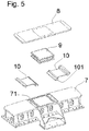
Figure 5 shows a deployment view of the connection between the structure and the frame. - As shown in the figures, the system for precision actuation and support for large mobiles structures is based on the existence of a fixed support structure (1) in which the mobile structure is secured by a series of frames (7) placed at different points, normally uniformly distributed.
- The fixed structure (1) has a central rail (3) which is guarded by lateral tracks (2) which has, on the outer surface thereof, preferably on both sides, the constitution and configuration of the stator of an electric linear motor (5), the rotor of which is located in a frame (7) and located in correspondence with the same, maintaining the air gap at a low and constant value. The fixed structure (1) has tracks (2) located on a plane parallel to that which defines the surface of the rail (3) on which a series of hydrostatic feet (4) present on the support face of the frame (7) slide, guaranteeing a correct and very close positioning of the stator/rotor of the actuating linear motor (5).
- In turn, each of the frames (7) in which the mobile structure is supported by the fixed structure (1) comprises:
- The rotor of an electric linear motor (5) arranged longitudinally, in correspondence with the rail (3) present on the fixed support structure (1).
- A series of hydrostatic feet (4) arranged along the face by which said frame (7) is supported by the track (2) of the fixed structure (1); which operate with a 60-70-micron layer of typical oil, thereby guaranteeing an approximation between the stator and the rotor of the linear motor which define an air gap less than 1 mm.
- Each frame (7) defines a connection mechanism in the driving mobile structure, via a flexible kinematic connection that permits relative movements between both (frame and structure), such that the mechanism is only affected in its operation through the small-scale deformations of the track via which same circulates, and not through the large-scale deformations of the structure. This mechanism comprises rigid connections (10) which open in opposite directions toward the directions of the movements of the mobile structure, supporting thereon a rigid plate (8), parallel to and above the frame (7), while between both elements (frame (7) and plate (8)) an elastomer (9) is placed, which occupies the central area of the connection means and is suitable for making a rigid connection in a vertical direction, but flexible at moments which enable relative rotation, without the appearance of secondary moments, which compensates for possible errors in the track.
- The fixed support structure (1) has a disc (11) on a plane parallel to the tracks (2) and the rail (3) on which the hydraulic brakes (6) act, incorporated by each of the frames (7).
Claims (6)
- An integrated system for precision actuation and support for large mobile structures, structures which slide over and are supported by a support structure (1) through a series of frames (7) which secure the mobile structure to said fixed support structure (1), characterized in that the support structure (1) comprises:- a rail (3) guarded by at least one lateral track (2), the outer surface of which constitutes the stator of an electric linear motor (5), the rotor of which is located in a frame (7) and located in correspondence with the same, maintaining the air gap at a low and constant value.- at least one track (2), located on a plane parallel to that which defines the surface of the rail (3) on which a series of hydrostatic feet (4) present on the support face of the frame (7) slide, which guarantee a correct and very close positioning of the stator/rotor of the actuating linear motor (5);while, in turn, each of the frames (7) in which the mobile structure is supported by the fixed structure (1) comprises:- the rotor of an electric linear motor (5), arranged longitudinally, in correspondence with the rail (3) present on the fixed support structure (1).- a series of hydrostatic feet (4) arranged along the face by which said frame is supported by the track (2) of the fixed structure (1);- a connection means between this frame (7) and the driving structure, via a kinematically compatible (flexible) connection that permits relative movements between both (frame and structure), such that the mechanism is only affected in its operation through the small-scale deformations of the track via which it circulates, and not through the large-scale deformations of the structure.
- The system, according to claim 1, characterized in that there are two tracks (2) on which the hydrostatic feet (4) fixed to the frame (7) are supported, and they are located parallel and on each side of the rail (3) which defines the stator of the linear motor (5).
- The system according to the preceding claims, characterized in that the connection means between the frame (7) and the structure comprise rigid connections (10) which open in opposite directions towards the directions of movement of the mobile structure, supporting thereon a rigid plate (8), parallel to and above the frame (7), while between both elements (frame (7) and plate (8)) an elastomer (9) is placed, which occupies the central area of the connection means, which is suitable for making a rigid connection in a vertical direction, but flexible at moments which enable relative rotation.
- The system according to the preceding claims, characterized in that the fixed support structure (1) has a disc (11) on a plane parallel to the tracks (2) and the rail (3) on which the hydraulic brakes (6) act, mounted on the frame (7).
- The system according to the preceding claims, characterized in that the hydrostatic feet operate with a 60-70-micron layer of typical oil.
- The system according to the preceding claims, characterized in that the air gap between the rail (3) which forms the stator of the linear motor and the rotor fixed in the frame (7), is less than 1 mm.
Applications Claiming Priority (1)
| Application Number | Priority Date | Filing Date | Title |
|---|---|---|---|
| PCT/ES2015/070058 WO2016120501A1 (en) | 2015-01-29 | 2015-01-29 | Integrated system for precision actuation and support for large mobile structures |
Publications (4)
| Publication Number | Publication Date |
|---|---|
| EP3252521A1 true EP3252521A1 (en) | 2017-12-06 |
| EP3252521A4 EP3252521A4 (en) | 2018-10-17 |
| EP3252521C0 EP3252521C0 (en) | 2025-11-19 |
| EP3252521B1 EP3252521B1 (en) | 2025-11-19 |
Family
ID=56542491
Family Applications (1)
| Application Number | Title | Priority Date | Filing Date |
|---|---|---|---|
| EP15879768.8A Active EP3252521B1 (en) | 2015-01-29 | 2015-01-29 | Integrated system for precision actuation and support for large mobile structures |
Country Status (5)
| Country | Link |
|---|---|
| US (1) | US10473158B2 (en) |
| EP (1) | EP3252521B1 (en) |
| CA (1) | CA2974764C (en) |
| ES (1) | ES3062957T3 (en) |
| WO (1) | WO2016120501A1 (en) |
Families Citing this family (3)
| Publication number | Priority date | Publication date | Assignee | Title |
|---|---|---|---|---|
| US10696777B2 (en) | 2015-06-16 | 2020-06-30 | Evonik Operations Gmbh | Aldehyde scavengers mixtures for polyurethane foams |
| CH718301B1 (en) * | 2019-12-07 | 2024-07-15 | Akribis Systems Pte Ltd | Ultra-low profile aerostatic bearing and method for its manufacture. |
| CN112068275B (en) * | 2020-09-08 | 2022-05-13 | 西安应用光学研究所 | Flexible supporting structure for back of optical element |
Family Cites Families (10)
| Publication number | Priority date | Publication date | Assignee | Title |
|---|---|---|---|---|
| FR2728695B1 (en) * | 1994-12-22 | 1997-03-28 | Aerospatiale | HIGH PRECISION ROTATION CONTROL DEVICE, ESPECIALLY FOR A TELESCOPE |
| US6196515B1 (en) | 1999-09-07 | 2001-03-06 | Lockheed Martin Corporation | Load equalization support system |
| DE19958567A1 (en) * | 1999-12-04 | 2001-06-07 | Zeiss Carl Jena Gmbh | Heavy duty precision bearing for an optical instrument |
| EP1637277A1 (en) * | 2004-09-17 | 2006-03-22 | CSEM Centre Suisse d'Electronique et de Microtechnique SA | Parallel kinematics machine with elastic joints |
| JP2007103657A (en) * | 2005-10-04 | 2007-04-19 | Canon Inc | Optical element holding apparatus, exposure apparatus, and device manufacturing method |
| ITVR20090093A1 (en) | 2009-06-25 | 2010-12-26 | Raffaele Tomelleri | HYDROSTATIC LATERAL DRIVING SYSTEM OF THE LIFTING STRUCTURE OF A LARGE TELESCOPE. |
| ITVR20090092A1 (en) | 2009-06-25 | 2010-12-26 | Raffaele Tomelleri | HYDROSTATIC SUPPORT FOR LARGE STRUCTURES AND IN PARTICULAR FOR LARGE TELESCOPES. |
| JP5480597B2 (en) * | 2009-11-04 | 2014-04-23 | ヤマハ発動機株式会社 | Linear conveyor |
| CN102436054B (en) * | 2011-12-29 | 2013-08-21 | 中国科学院长春光学精密机械与物理研究所 | Composite primary reflector supporting device for large telescope |
| ES2618014B2 (en) * | 2014-04-10 | 2018-02-15 | Aktiebolaget Skf | Hydrostatic bearing to support a telescope |
-
2015
- 2015-01-29 US US15/546,104 patent/US10473158B2/en active Active
- 2015-01-29 ES ES15879768T patent/ES3062957T3/en active Active
- 2015-01-29 EP EP15879768.8A patent/EP3252521B1/en active Active
- 2015-01-29 CA CA2974764A patent/CA2974764C/en active Active
- 2015-01-29 WO PCT/ES2015/070058 patent/WO2016120501A1/en not_active Ceased
Also Published As
| Publication number | Publication date |
|---|---|
| EP3252521C0 (en) | 2025-11-19 |
| US20180017106A1 (en) | 2018-01-18 |
| EP3252521B1 (en) | 2025-11-19 |
| CA2974764C (en) | 2023-07-04 |
| CA2974764A1 (en) | 2016-08-04 |
| ES3062957T3 (en) | 2026-04-14 |
| US10473158B2 (en) | 2019-11-12 |
| EP3252521A4 (en) | 2018-10-17 |
| WO2016120501A1 (en) | 2016-08-04 |
Similar Documents
| Publication | Publication Date | Title |
|---|---|---|
| CA2974764C (en) | Integrated system for precision actuation and support for large mobile structures | |
| US9976694B2 (en) | Two-axis mounting base | |
| US9174391B2 (en) | Device for producing three-dimensional models | |
| CN103197397B (en) | Whole four-dimensional high-precision adjusting device for grating splicing | |
| Cayrel | E-ELT optomechanics: overview | |
| RU2430874C2 (en) | Electromechanical lifting device | |
| DE102013201506A1 (en) | Optical component | |
| DE102013201509A1 (en) | Optical component | |
| EP2906834B1 (en) | Actuator | |
| CN116238724B (en) | Micro-low gravity simulation system for complex multi-body targets | |
| CN105817776B (en) | Laser processing machine with gravity compensation device | |
| DE202014008041U1 (en) | Surveyor with traveling wave drive | |
| JP2015075769A (en) | Active space telescope with suspended reflector | |
| US5822116A (en) | High-accuracy rotation control device, in particular for telescopes | |
| ES2624870T3 (en) | Transfer center for machining with chip removal of at least one workpiece, with a position compensation system. | |
| DE202007005801U1 (en) | Device for the active horizontal stabilization of carrier systems of optical or radio devices | |
| ES2306211T3 (en) | LASER PUNCHING MACHINE. | |
| CN107942503A (en) | Extremely large telescope height shafting supports and driving hydraulic pressure whiffletree control mobile systems | |
| US7336408B2 (en) | Reflecting mirror supporting mechanism | |
| CN108594423B (en) | A flexible airborne system for azimuth shafting support and precision drive for very large telescopes | |
| JP4459142B2 (en) | Spacecraft motion simulator | |
| DE102012217485B4 (en) | Gravity compensation device and method | |
| DE202006020745U1 (en) | telescope mount | |
| Pirnay et al. | Thirty meter telescope: preliminary design of the M2 support system and positioner | |
| CN105552554B (en) | A kind of Three Degree Of Freedom posture adjusting device and attitude-adjusting method suitable for radar antenna side block |
Legal Events
| Date | Code | Title | Description |
|---|---|---|---|
| STAA | Information on the status of an ep patent application or granted ep patent |
Free format text: STATUS: THE INTERNATIONAL PUBLICATION HAS BEEN MADE |
|
| PUAI | Public reference made under article 153(3) epc to a published international application that has entered the european phase |
Free format text: ORIGINAL CODE: 0009012 |
|
| STAA | Information on the status of an ep patent application or granted ep patent |
Free format text: STATUS: REQUEST FOR EXAMINATION WAS MADE |
|
| 17P | Request for examination filed |
Effective date: 20170720 |
|
| AK | Designated contracting states |
Kind code of ref document: A1 Designated state(s): AL AT BE BG CH CY CZ DE DK EE ES FI FR GB GR HR HU IE IS IT LI LT LU LV MC MK MT NL NO PL PT RO RS SE SI SK SM TR |
|
| AX | Request for extension of the european patent |
Extension state: BA ME |
|
| DAX | Request for extension of the european patent (deleted) | ||
| A4 | Supplementary search report drawn up and despatched |
Effective date: 20180914 |
|
| RIC1 | Information provided on ipc code assigned before grant |
Ipc: G02B 7/183 20060101ALI20180911BHEP Ipc: G02B 7/198 20060101ALI20180911BHEP Ipc: F16C 29/02 20060101ALI20180911BHEP Ipc: G02B 23/16 20060101AFI20180911BHEP Ipc: F16C 32/06 20060101ALI20180911BHEP |
|
| STAA | Information on the status of an ep patent application or granted ep patent |
Free format text: STATUS: EXAMINATION IS IN PROGRESS |
|
| 17Q | First examination report despatched |
Effective date: 20201001 |
|
| 17Q | First examination report despatched |
Effective date: 20201028 |
|
| RIC1 | Information provided on ipc code assigned before grant |
Ipc: F16F 15/08 20060101ALI20250512BHEP Ipc: F16C 32/06 20060101ALI20250512BHEP Ipc: F16C 29/02 20060101ALI20250512BHEP Ipc: G02B 7/198 20060101ALI20250512BHEP Ipc: G02B 7/183 20060101ALI20250512BHEP Ipc: G02B 23/16 20060101AFI20250512BHEP |
|
| GRAP | Despatch of communication of intention to grant a patent |
Free format text: ORIGINAL CODE: EPIDOSNIGR1 |
|
| STAA | Information on the status of an ep patent application or granted ep patent |
Free format text: STATUS: GRANT OF PATENT IS INTENDED |
|
| INTG | Intention to grant announced |
Effective date: 20250707 |
|
| GRAS | Grant fee paid |
Free format text: ORIGINAL CODE: EPIDOSNIGR3 |
|
| GRAA | (expected) grant |
Free format text: ORIGINAL CODE: 0009210 |
|
| STAA | Information on the status of an ep patent application or granted ep patent |
Free format text: STATUS: THE PATENT HAS BEEN GRANTED |
|
| AK | Designated contracting states |
Kind code of ref document: B1 Designated state(s): AL AT BE BG CH CY CZ DE DK EE ES FI FR GB GR HR HU IE IS IT LI LT LU LV MC MK MT NL NO PL PT RO RS SE SI SK SM TR |
|
| REG | Reference to a national code |
Ref country code: CH Ref legal event code: F10 Free format text: ST27 STATUS EVENT CODE: U-0-0-F10-F00 (AS PROVIDED BY THE NATIONAL OFFICE) Effective date: 20251119 Ref country code: GB Ref legal event code: FG4D |
|
| REG | Reference to a national code |
Ref country code: DE Ref legal event code: R096 Ref document number: 602015092694 Country of ref document: DE |
|
| REG | Reference to a national code |
Ref country code: IE Ref legal event code: FG4D |
|
| U01 | Request for unitary effect filed |
Effective date: 20251218 |
|
| U07 | Unitary effect registered |
Designated state(s): AT BE BG DE DK EE FI FR IT LT LU LV MT NL PT RO SE SI Effective date: 20260102 |
|
| U20 | Renewal fee for the european patent with unitary effect paid |
Year of fee payment: 12 Effective date: 20260127 |
|
| PGFP | Annual fee paid to national office [announced via postgrant information from national office to epo] |
Ref country code: ES Payment date: 20260217 Year of fee payment: 12 |
|
| PG25 | Lapsed in a contracting state [announced via postgrant information from national office to epo] |
Ref country code: NO Free format text: LAPSE BECAUSE OF FAILURE TO SUBMIT A TRANSLATION OF THE DESCRIPTION OR TO PAY THE FEE WITHIN THE PRESCRIBED TIME-LIMIT Effective date: 20260219 |
|
| PG25 | Lapsed in a contracting state [announced via postgrant information from national office to epo] |
Ref country code: HR Free format text: LAPSE BECAUSE OF FAILURE TO SUBMIT A TRANSLATION OF THE DESCRIPTION OR TO PAY THE FEE WITHIN THE PRESCRIBED TIME-LIMIT Effective date: 20251119 |
|
| REG | Reference to a national code |
Ref country code: ES Ref legal event code: FG2A Ref document number: 3062957 Country of ref document: ES Kind code of ref document: T3 Effective date: 20260414 |
|
| PG25 | Lapsed in a contracting state [announced via postgrant information from national office to epo] |
Ref country code: RS Free format text: LAPSE BECAUSE OF FAILURE TO SUBMIT A TRANSLATION OF THE DESCRIPTION OR TO PAY THE FEE WITHIN THE PRESCRIBED TIME-LIMIT Effective date: 20260219 |
|
| PG25 | Lapsed in a contracting state [announced via postgrant information from national office to epo] |
Ref country code: IS Free format text: LAPSE BECAUSE OF FAILURE TO SUBMIT A TRANSLATION OF THE DESCRIPTION OR TO PAY THE FEE WITHIN THE PRESCRIBED TIME-LIMIT Effective date: 20260319 |
|
| PG25 | Lapsed in a contracting state [announced via postgrant information from national office to epo] |
Ref country code: PL Free format text: LAPSE BECAUSE OF FAILURE TO SUBMIT A TRANSLATION OF THE DESCRIPTION OR TO PAY THE FEE WITHIN THE PRESCRIBED TIME-LIMIT Effective date: 20251119 |
|
| PG25 | Lapsed in a contracting state [announced via postgrant information from national office to epo] |
Ref country code: SM Free format text: LAPSE BECAUSE OF FAILURE TO SUBMIT A TRANSLATION OF THE DESCRIPTION OR TO PAY THE FEE WITHIN THE PRESCRIBED TIME-LIMIT Effective date: 20251119 |
|
| PGFP | Annual fee paid to national office [announced via postgrant information from national office to epo] |
Ref country code: GB Payment date: 20260421 Year of fee payment: 12 |
|
| PG25 | Lapsed in a contracting state [announced via postgrant information from national office to epo] |
Ref country code: CZ Free format text: LAPSE BECAUSE OF FAILURE TO SUBMIT A TRANSLATION OF THE DESCRIPTION OR TO PAY THE FEE WITHIN THE PRESCRIBED TIME-LIMIT Effective date: 20251119 |
|
| PG25 | Lapsed in a contracting state [announced via postgrant information from national office to epo] |
Ref country code: SK Free format text: LAPSE BECAUSE OF FAILURE TO SUBMIT A TRANSLATION OF THE DESCRIPTION OR TO PAY THE FEE WITHIN THE PRESCRIBED TIME-LIMIT Effective date: 20251119 |