EP3252448A1 - Cable attachment device, connection assembly and method for measuring cable temperature - Google Patents
Cable attachment device, connection assembly and method for measuring cable temperature Download PDFInfo
- Publication number
- EP3252448A1 EP3252448A1 EP17172302.6A EP17172302A EP3252448A1 EP 3252448 A1 EP3252448 A1 EP 3252448A1 EP 17172302 A EP17172302 A EP 17172302A EP 3252448 A1 EP3252448 A1 EP 3252448A1
- Authority
- EP
- European Patent Office
- Prior art keywords
- cables
- attachment device
- cable
- probe
- harnesses
- Prior art date
- Legal status (The legal status is an assumption and is not a legal conclusion. Google has not performed a legal analysis and makes no representation as to the accuracy of the status listed.)
- Granted
Links
Images

Classifications
-
- B—PERFORMING OPERATIONS; TRANSPORTING
- B60—VEHICLES IN GENERAL
- B60R—VEHICLES, VEHICLE FITTINGS, OR VEHICLE PARTS, NOT OTHERWISE PROVIDED FOR
- B60R16/00—Electric or fluid circuits specially adapted for vehicles and not otherwise provided for; Arrangement of elements of electric or fluid circuits specially adapted for vehicles and not otherwise provided for
- B60R16/02—Electric or fluid circuits specially adapted for vehicles and not otherwise provided for; Arrangement of elements of electric or fluid circuits specially adapted for vehicles and not otherwise provided for electric constitutive elements
- B60R16/0207—Wire harnesses
- B60R16/0215—Protecting, fastening and routing means therefor
-
- H—ELECTRICITY
- H01—ELECTRIC ELEMENTS
- H01R—ELECTRICALLY-CONDUCTIVE CONNECTIONS; STRUCTURAL ASSOCIATIONS OF A PLURALITY OF MUTUALLY-INSULATED ELECTRICAL CONNECTING ELEMENTS; COUPLING DEVICES; CURRENT COLLECTORS
- H01R13/00—Details of coupling devices of the kinds covered by groups H01R12/70 or H01R24/00 - H01R33/00
- H01R13/66—Structural association with built-in electrical component
- H01R13/665—Structural association with built-in electrical component with built-in electronic circuit
- H01R13/6683—Structural association with built-in electrical component with built-in electronic circuit with built-in sensor
-
- H—ELECTRICITY
- H01—ELECTRIC ELEMENTS
- H01R—ELECTRICALLY-CONDUCTIVE CONNECTIONS; STRUCTURAL ASSOCIATIONS OF A PLURALITY OF MUTUALLY-INSULATED ELECTRICAL CONNECTING ELEMENTS; COUPLING DEVICES; CURRENT COLLECTORS
- H01R13/00—Details of coupling devices of the kinds covered by groups H01R12/70 or H01R24/00 - H01R33/00
- H01R13/46—Bases; Cases
- H01R13/516—Means for holding or embracing insulating body, e.g. casing, hoods
-
- G—PHYSICS
- G01—MEASURING; TESTING
- G01K—MEASURING TEMPERATURE; MEASURING QUANTITY OF HEAT; THERMALLY-SENSITIVE ELEMENTS NOT OTHERWISE PROVIDED FOR
- G01K1/00—Details of thermometers not specially adapted for particular types of thermometer
- G01K1/14—Supports; Fastening devices; Arrangements for mounting thermometers in particular locations
-
- G—PHYSICS
- G01—MEASURING; TESTING
- G01K—MEASURING TEMPERATURE; MEASURING QUANTITY OF HEAT; THERMALLY-SENSITIVE ELEMENTS NOT OTHERWISE PROVIDED FOR
- G01K1/00—Details of thermometers not specially adapted for particular types of thermometer
- G01K1/14—Supports; Fastening devices; Arrangements for mounting thermometers in particular locations
- G01K1/143—Supports; Fastening devices; Arrangements for mounting thermometers in particular locations for measuring surface temperatures
-
- H—ELECTRICITY
- H01—ELECTRIC ELEMENTS
- H01B—CABLES; CONDUCTORS; INSULATORS; SELECTION OF MATERIALS FOR THEIR CONDUCTIVE, INSULATING OR DIELECTRIC PROPERTIES
- H01B7/00—Insulated conductors or cables characterised by their form
- H01B7/0045—Cable-harnesses
-
- H—ELECTRICITY
- H01—ELECTRIC ELEMENTS
- H01B—CABLES; CONDUCTORS; INSULATORS; SELECTION OF MATERIALS FOR THEIR CONDUCTIVE, INSULATING OR DIELECTRIC PROPERTIES
- H01B7/00—Insulated conductors or cables characterised by their form
- H01B7/40—Insulated conductors or cables characterised by their form with arrangements for facilitating mounting or securing
-
- H—ELECTRICITY
- H01—ELECTRIC ELEMENTS
- H01R—ELECTRICALLY-CONDUCTIVE CONNECTIONS; STRUCTURAL ASSOCIATIONS OF A PLURALITY OF MUTUALLY-INSULATED ELECTRICAL CONNECTING ELEMENTS; COUPLING DEVICES; CURRENT COLLECTORS
- H01R13/00—Details of coupling devices of the kinds covered by groups H01R12/70 or H01R24/00 - H01R33/00
- H01R13/72—Means for accommodating flexible lead within the holder
-
- H—ELECTRICITY
- H02—GENERATION; CONVERSION OR DISTRIBUTION OF ELECTRIC POWER
- H02G—INSTALLATION OF ELECTRIC CABLES OR LINES, OR OF COMBINED OPTICAL AND ELECTRIC CABLES OR LINES
- H02G3/00—Installations of electric cables or lines or protective tubing therefor in or on buildings, equivalent structures or vehicles
- H02G3/02—Details
- H02G3/04—Protective tubing or conduits, e.g. cable ladders or cable troughs
- H02G3/0437—Channels
-
- F—MECHANICAL ENGINEERING; LIGHTING; HEATING; WEAPONS; BLASTING
- F16—ENGINEERING ELEMENTS AND UNITS; GENERAL MEASURES FOR PRODUCING AND MAINTAINING EFFECTIVE FUNCTIONING OF MACHINES OR INSTALLATIONS; THERMAL INSULATION IN GENERAL
- F16L—PIPES; JOINTS OR FITTINGS FOR PIPES; SUPPORTS FOR PIPES, CABLES OR PROTECTIVE TUBING; MEANS FOR THERMAL INSULATION IN GENERAL
- F16L3/00—Supports for pipes, cables or protective tubing, e.g. hangers, holders, clamps, cleats, clips, brackets
- F16L3/08—Supports for pipes, cables or protective tubing, e.g. hangers, holders, clamps, cleats, clips, brackets substantially surrounding the pipe, cable or protective tubing
- F16L3/12—Supports for pipes, cables or protective tubing, e.g. hangers, holders, clamps, cleats, clips, brackets substantially surrounding the pipe, cable or protective tubing comprising a member substantially surrounding the pipe, cable or protective tubing
-
- H—ELECTRICITY
- H01—ELECTRIC ELEMENTS
- H01R—ELECTRICALLY-CONDUCTIVE CONNECTIONS; STRUCTURAL ASSOCIATIONS OF A PLURALITY OF MUTUALLY-INSULATED ELECTRICAL CONNECTING ELEMENTS; COUPLING DEVICES; CURRENT COLLECTORS
- H01R2201/00—Connectors or connections adapted for particular applications
- H01R2201/26—Connectors or connections adapted for particular applications for vehicles
Definitions
- the invention relates to the field of automobile vehicles and notably, but not exclusively, to the fields of electrical cabling for motor vehicles and of electrical connectors for motor vehicles.
- the idea is to measure the temperature of each cable by means of a temperature probe (or sensor), respectively placed in the vicinity of the latter on a fixed support on a connection receptacle.
- One aim of the invention is to overcome at least one of these drawbacks.
- a cable attachment device made of plastic material comprising at least two harnesses, each for receiving a respective cable.
- the attachment device comprises, for example, as many harnesses as cables to be attached together.
- the attachment device comprises a single accommodation, in between these cables, for accommodating a single temperature probe.
- This accommodation comprises a wall in contact with which, on one side, the probe is placed, and on the other side a cable.
- the probe is for example situated in the middle, in the centre, of the assembly of cables attached together by the attachment device, and all in contact with the wall of an accommodation within which the probe is placed.
- This attachment device could comprise one and/or the other of the following features considered independently from one another or in combination with one or more others:
- the invention relates to an electrical connection assembly comprising a connector, at least two cables and an attachment device holding these cables together.
- This attachment device then comprises at least two harnesses within each of which a cable can be placed.
- the attachment device furthermore comprises a single accommodation between these cables for accommodating a single temperature probe, this accommodation comprising a wall in contact with which, on one side, the probe is placed, and on the other side a cable.
- This assembly could comprise one and/or the other of the following features considered independently from one another or in combination with one or more others:
- the invention relates to a method for measuring the temperature of electrical cables of a motor vehicle, in which are provided at least two cables, a cable attachment device made of plastic material comprising at least two harnesses, each for respectively receiving a cable, and a temperature probe, characterized in that a single temperature probe is accommodated within the attachment device and in that the temperature of the cables is measured by means of this single probe placed in contact with a wall, itself in contact with a cable.
- a first exemplary embodiment of an attachment device 1 according to the invention is described herein below with reference to Figures 1 and 2 .
- the attachment device 1 is designed to be mounted in a connection assembly comprising a connector 2 for a charging point of an electric vehicle (see Figure 2 ).
- a connection assembly comprising a connector 2 for a charging point of an electric vehicle (see Figure 2 ).
- the currents flowing through the cables 4, 6, 8, 10, 12 connected to this connector 2 may for example reach 125 A.
- the cross-section of these cables is therefore large. It is for example 16mm 2 for three phase cables 4, 6, 8 and the ground cable 10.
- the cables 4, 6, 8, 10 are therefore relatively rigid and the attachment device 1 needs to be robust in order to hold the whole assembly without breaking or deforming.
- the attachment device 1 comprises harnesses 14, 16, 18, 20, 22 (at least one harness per cable whose temperature it is desired to monitor - see Figure 1 ) forming a "C" in transverse cross-section whose free ends must be able to be parted in order to insert a cable 4, 6, 8, 10 or 12 into it.
- the attachment device 1 must therefore exhibit certain flexibility.
- the attachment device 1 is a single block made of moulded plastic material.
- the plastic material and the dimensioning of the attachment device are chosen so that, as indicated hereinabove, the attachment device 1 is sufficiently robust, while at the same time conserving the possibility of elastically deforming it.
- the plastic material is chosen in such a manner that the attachment device renders the connection assembly lighter than the solutions of the prior art: taping up, filling of a cavity comprising a temperature probe (or "potting" according to the terminology of the art), etc.
- the plastic material is for example chosen from within the list comprising polyamide (PA) and Polybutylene Terephthalate (PBT).
- the attachment device 1 comprises five harnesses 14, 16, 18, 20, 22.
- Four 14, 16, 18, 20 of these harnesses are divided into two symmetrical pairs (14, 16 and 18, 20) on either side of a rectangular cavity 24 forming an accommodation designed to receive a temperature probe 28 (see Figure 2 ).
- Each harness 14, 16, 18, 20 or 22 forms a claw enclosing a cable 4, 6, 8, 10 or 12 so as to retain the attachment device 1 on this cable.
- the attachment device 1 thus holds all of the cables 4, 6, 8, 10, 12 together.
- the rectangular cavity 24 forms a cavity which extends along a longitudinal axis L with an essentially rectangular cross-section (generally speaking, the cavity - or accommodation - 24 is not necessarily rectangular and may for example have any given cylindrical shape, of revolution or otherwise).
- the transverse cross-section of this rectangular cavity 24, perpendicular to the longitudinal axis L, comprises two small sides 30, 32 and two large sides 34, 36.
- the wall 25 of the rectangular cavity 24 has a thickness at the apices of the rectangle of the transverse cross-section for example close to, or equal to, 1mm.
- Each cable 4, 6, 8, 10, 12 is thus positioned equidistant from the temperature probe 28, in contact with the wall 25, whereas the probe 28 is placed on the other side of the wall 25, also in contact with the latter.
- a partition 38 separates the two harnesses (14, 16 or 18, 20) of each pair of harnesses.
- This partition 38 is essentially perpendicular to the large sides 34, 36 of the rectangular cavity 24.
- a flexible gutter 40 forming a hook essentially extends from one edge of the rectangular cavity 24 (in other words, from the apex of the rectangle of the transverse cross-section) and returns towards its free end towards the plane of a partition 38.
- Each partition 38 and a gutter 40 thus form a harness 14, 16, 18, 20 in which a cable 4, 6, 8, 10 of large diameter (in other words one of the three phase cables or the ground cable) can be clamped and retained.
- the free edge of each gutter comprises a ledge 42 so as to form a flare on the opening of each harness 14, 16, 18, 20 in order to facilitate the insertion of a cable into the latter.
- a fifth harness 22 is formed between two pairs of harnesses, on one of the small sides 30, 32 of the rectangular cavity 24.
- This fifth harness 22 is intended to receive and hold the cable of the neutral 12.
- the latter has a smaller cross-section that the four preceding ones 4, 6, 8, 10, which is for example 4mm 2 .
- the free edge of this fifth harness 22 comprises, on either side, a ledge 44 forming a flare facilitating the insertion of a cable 12 into the latter.
- the small face of the rectangular cavity 24, opposite to that on which the fifth harness 22 is formed, comprises a reinforcement 46 endowing the attachment device 1 with a greater robustness.
- the attachment device 1 is shown with the cables 4, 6, 8, 10, 12 inserted into the harnesses 14, 16, 18, 20, 22, together with the probe 28 inserted into its accommodation formed from the rectangular cavity 24.
- the attachment device 1 is presented with the longitudinal axis L of the rectangular cavity 24 parallel to that of the cables 4, 6, 8, 10, 12 over their portion inserted into the harnesses 14, 16, 18, 20, 22, and parallel to the longitudinal axes of the contacts (not visible in the figures) accommodated within the receptacle 46 of the connector 2.
- Each gutter 40 receiving a cable 4, 6, 8 or 10 of large cross-section forms means for applying pressure in order to hold and press this cable 4, 6, 8 or 10 against the wall 25 of the rectangular cavity 24 receiving the probe 28.
- Figure 6 shows an electrical connection assembly comprising a connector 2, cables 4, 6, 8, 10, 12 and an attachment device 1 holding these cables 4, 6, 8, 10, 12 together.
- the cables 4, 6, 8, 10, 12 extend away from the receptacle 46 in a direction substantially parallel to the plane of the receptacle 46 (this plane is essentially perpendicular to the axis of the eyelets 50 for fixing the receptacle 46 onto a support).
- the cover 48 comprises an opening 52 for the passage of the cables.
- the attachment device 1 is mounted on the cables between the opening 52 of the cover 48 and the receptacle 46 (hence with the longitudinal axis L of the rectangular cavity 24 more or less parallel to the plane of the receptacle 46 in contrast to what is shown in Figure 2 .
- FIG 3 shows a second embodiment of an attachment device 1 according to the invention.
- the attachment device 1 is shown in a transverse cross-section halfway along its length (i.e. its dimension parallel to the longitudinal axis L).
- This embodiment differs from the preceding one essentially by the shape of the harnesses 14, 16, 18, 20, 22.
- the cables with a wider cross-section 4, 6, 8, 10 are no longer clamped between a partition and a flexible gutter. Each of them is enclosed within a tubular cavity enclosed by a strap 54.
- the straps 54 avoid having to make use of less productive methods such as wrapping with an adhesive tape.
- the rectangular cavity 24 is designed to receive a temperature probe 28 (see Figure 5 ).
- the rectangular cavity 24 has essentially the same shape as in the preceding embodiment.
- Each strap 54 is connected to the central block 56 comprising the rectangular cavity 24 with an articulation 58 essentially parallel to the longitudinal axis L of the rectangular cavity 24.
- Each strap 54 also comprises gutters 40 similar to those of the central block 56.
- the free end of each strap 54, on the side opposite to the articulation 58, is equipped with a hook 60 allowing each strap 54 to be closed over a pair of cables of large cross-section.
- One of the hooks 60 also closes over a harness 22 receiving a cable 12 with a smaller cross-section.
- one strap 54 is closed. It is observed that the gutters 40 of the central block 56 and those of a strap 54 form tubular cavities whose wall is almost closed. Each tubular cavity extends longitudinally parallel to the longitudinal axis L of the rectangular cavity 24. As shown in Figure 5 , when the straps 54 are closed over these tubular cavities and the latter receive a cable 4, 6, 8, 10 or 12, the straps 54 form means for applying pressure in order to hold and press each cable against the wall 25 of the rectangular cavity 24 receiving the probe 28.
- the attachment device 1 is mounted on the cables 4, 6, 8, 10, 12 between the opening of the cover 48 and the receptacle 46.
- the attachment device 1 is retained on the cables 4, 6, 8, 10, 12 but is not rigidly attached to the receptacle 46.
- the attachment device 1 is self-supported by the cables 4, 6, 8, 10, 12.
- the attachment device 1 also plays a support role, notably during the phases for assembly of the connector 2, since it holds all the cables 4, 6, 8, 10, 12 of the connector 2, together with the probe 28. This facilitates the cabling operations and operations for mounting of the connector 2.
- an attachment device 1 for example such as that of the first or of the second embodiment described hereinabove
- harnesses 14, 16, 18, 20 peripheral to a single central cavity 24, in which a temperature probe 28 is placed.
- the cables 4, 6, 8, 10 whose temperature it is desired to measure are placed in the harnesses 14, 16, 18, 20. Their temperature is measured through the wall 25 of the cavity 24 in contact with which they are elastically pressed.
Landscapes
- Physics & Mathematics (AREA)
- General Physics & Mathematics (AREA)
- Engineering & Computer Science (AREA)
- Microelectronics & Electronic Packaging (AREA)
- Architecture (AREA)
- Civil Engineering (AREA)
- Structural Engineering (AREA)
- Mechanical Engineering (AREA)
- Details Of Connecting Devices For Male And Female Coupling (AREA)
- Connector Housings Or Holding Contact Members (AREA)
- Measuring Temperature Or Quantity Of Heat (AREA)
- Installation Of Indoor Wiring (AREA)
Abstract
Description
- The invention relates to the field of automobile vehicles and notably, but not exclusively, to the fields of electrical cabling for motor vehicles and of electrical connectors for motor vehicles.
- In the field of motor vehicles and notably of electric or hybrid vehicles, it is necessary to detect abnormal heating events in electrical cables in order to prevent any damage, or even fire, to the vehicles. This aspect is particularly important during operations for recharging batteries, which may be carried out with current intensities that can go up to 63 A, 97 A, or even 125 A.
- For this purpose, as disclosed for example in the document
JP5422479 - However, this type of device of the prior art notably exhibits the following drawbacks:
- the support is designed and fabricated for a particular model of receptacle; changing a model of receptacle may require a new support to be designed;
- its size is relatively bulky;
- the overall cost of this function "measurement of temperature of the cables" is also relatively high.
- One aim of the invention is to overcome at least one of these drawbacks.
- This aim is at least partially achieved by virtue of a cable attachment device made of plastic material comprising at least two harnesses, each for receiving a respective cable. The attachment device comprises, for example, as many harnesses as cables to be attached together. On the other hand, the attachment device comprises a single accommodation, in between these cables, for accommodating a single temperature probe. This accommodation comprises a wall in contact with which, on one side, the probe is placed, and on the other side a cable. The probe is for example situated in the middle, in the centre, of the assembly of cables attached together by the attachment device, and all in contact with the wall of an accommodation within which the probe is placed.
- Thus, using an attachment device fixed onto the cables themselves avoids having to be dependent on a particular model of receptacle. Furthermore, using a single probe, instead of one probe per cable, allows both the cost of and the space occupied by the device for measuring the temperature of the cables to be reduced.
- This attachment device could comprise one and/or the other of the following features considered independently from one another or in combination with one or more others:
- the attachment device is constructed from a single block;
- the accommodation is essentially equidistant from the cables whose temperature it is desired to measure;
- the attachment device comprises means for applying pressure in order to maintain the cables placed in the harnesses in contact with a wall of the accommodation designed to receive the probe; for example, the means for applying pressure comprise straps, or clamps, for respectively enclosing each cable within a harness.
- According to another aspect, the invention relates to an electrical connection assembly comprising a connector, at least two cables and an attachment device holding these cables together. This attachment device then comprises at least two harnesses within each of which a cable can be placed. The attachment device furthermore comprises a single accommodation between these cables for accommodating a single temperature probe, this accommodation comprising a wall in contact with which, on one side, the probe is placed, and on the other side a cable.
- This assembly could comprise one and/or the other of the following features considered independently from one another or in combination with one or more others:
- the attachment device is self-supported by the cables; in other words it is not mounted on any other element except for one or more cables; in particular, the attachment device is not supported by a connector receptacle;
- the accommodation is essentially equidistant from each of the cables;
- the assembly comprises a receptacle in which contacts connected to the cables are accommodated and a cover for at least partially enclosing the receptacle; the cover comprises an opening for the passage of the cables and the attachment device is mounted on the cables between the opening of the cover and the receptacle;
- at least two harnesses form clips for retaining the attachment device respectively on each of the cables placed in one of these two harnesses and for holding these cables together.
- According to another aspect, the invention relates to a method for measuring the temperature of electrical cables of a motor vehicle, in which are provided at least two cables, a cable attachment device made of plastic material comprising at least two harnesses, each for respectively receiving a cable, and a temperature probe, characterized in that a single temperature probe is accommodated within the attachment device and in that the temperature of the cables is measured by means of this single probe placed in contact with a wall, itself in contact with a cable.
- Other features and advantages of the invention will become apparent upon reading the detailed description that follows and also on the appended drawings. In these drawings:
-
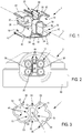
Figure 1 shows schematically in perspective a first exemplary embodiment of an attachment device according to the invention; -
Figure 2 shows schematically in elevation one example of a connection assembly comprising the attachment device inFigure 1 : -
Figure 3 shows schematically in a transverse cross-section a second exemplary embodiment of an attachment device according to the invention; -
Figure 4 shows schematically in perspective the attachment device inFigure 3 , with a closed strap; -
Figure 5 shows schematically in elevation another example of a connection assembly comprising the attachment device inFigures 3 and4 : -
Figure 6 shows schematically in perspective a connection assembly such as that inFigures 2 and5 , with a cover. - In the figures, the same references denote identical or similar elements.
- A first exemplary embodiment of an
attachment device 1 according to the invention is described herein below with reference toFigures 1 and 2 . - According to this example, the
attachment device 1 is designed to be mounted in a connection assembly comprising aconnector 2 for a charging point of an electric vehicle (seeFigure 2 ). During charging, the currents flowing through thecables connector 2 may for example reach 125 A. The cross-section of these cables is therefore large. It is for example 16mm2 for threephase cables ground cable 10. Thecables attachment device 1 needs to be robust in order to hold the whole assembly without breaking or deforming. Furthermore, theattachment device 1 comprisesharnesses Figure 1 ) forming a "C" in transverse cross-section whose free ends must be able to be parted in order to insert acable attachment device 1 must therefore exhibit certain flexibility. - The
attachment device 1 is a single block made of moulded plastic material. The plastic material and the dimensioning of the attachment device are chosen so that, as indicated hereinabove, theattachment device 1 is sufficiently robust, while at the same time conserving the possibility of elastically deforming it. Furthermore, the plastic material is chosen in such a manner that the attachment device renders the connection assembly lighter than the solutions of the prior art: taping up, filling of a cavity comprising a temperature probe (or "potting" according to the terminology of the art), etc. The plastic material is for example chosen from within the list comprising polyamide (PA) and Polybutylene Terephthalate (PBT). - In the example shown in
Figure 1 , theattachment device 1 comprises fiveharnesses rectangular cavity 24 forming an accommodation designed to receive a temperature probe 28 (seeFigure 2 ). Eachharness cable attachment device 1 on this cable. Theattachment device 1 thus holds all of thecables - The
rectangular cavity 24 forms a cavity which extends along a longitudinal axis L with an essentially rectangular cross-section (generally speaking, the cavity - or accommodation - 24 is not necessarily rectangular and may for example have any given cylindrical shape, of revolution or otherwise). The transverse cross-section of thisrectangular cavity 24, perpendicular to the longitudinal axis L, comprises twosmall sides large sides wall 25 of therectangular cavity 24 has a thickness at the apices of the rectangle of the transverse cross-section for example close to, or equal to, 1mm. Eachcable temperature probe 28, in contact with thewall 25, whereas theprobe 28 is placed on the other side of thewall 25, also in contact with the latter. - A
partition 38 separates the two harnesses (14, 16 or 18, 20) of each pair of harnesses. Thispartition 38 is essentially perpendicular to thelarge sides rectangular cavity 24. Aflexible gutter 40 forming a hook essentially extends from one edge of the rectangular cavity 24 (in other words, from the apex of the rectangle of the transverse cross-section) and returns towards its free end towards the plane of apartition 38. Eachpartition 38 and agutter 40 thus form aharness cable ledge 42 so as to form a flare on the opening of eachharness - A
fifth harness 22 is formed between two pairs of harnesses, on one of thesmall sides rectangular cavity 24. Thisfifth harness 22 is intended to receive and hold the cable of the neutral 12. The latter has a smaller cross-section that the four precedingones fifth harness 22 comprises, on either side, aledge 44 forming a flare facilitating the insertion of acable 12 into the latter. - The small face of the
rectangular cavity 24, opposite to that on which thefifth harness 22 is formed, comprises areinforcement 46 endowing theattachment device 1 with a greater robustness. - In
Figure 2 , theattachment device 1 is shown with thecables harnesses probe 28 inserted into its accommodation formed from therectangular cavity 24. Theattachment device 1 is presented with the longitudinal axis L of therectangular cavity 24 parallel to that of thecables harnesses receptacle 46 of theconnector 2. Eachgutter 40 receiving acable cable wall 25 of therectangular cavity 24 receiving theprobe 28. -
Figure 6 shows an electrical connection assembly comprising aconnector 2,cables attachment device 1 holding thesecables - In this
Figure 6 , it can be seen that, when thereceptacle 46 is closed by acover 48, thecables receptacle 46 in a direction substantially parallel to the plane of the receptacle 46 (this plane is essentially perpendicular to the axis of theeyelets 50 for fixing thereceptacle 46 onto a support). Thecover 48 comprises anopening 52 for the passage of the cables. Theattachment device 1 is mounted on the cables between the opening 52 of thecover 48 and the receptacle 46 (hence with the longitudinal axis L of therectangular cavity 24 more or less parallel to the plane of thereceptacle 46 in contrast to what is shown inFigure 2 . -
Figure 3 shows a second embodiment of anattachment device 1 according to the invention. In this Figure, theattachment device 1 is shown in a transverse cross-section halfway along its length (i.e. its dimension parallel to the longitudinal axis L). - This embodiment differs from the preceding one essentially by the shape of the
harnesses wider cross-section strap 54. Thestraps 54 avoid having to make use of less productive methods such as wrapping with an adhesive tape. - As in the preceding embodiment, four harnesses 14, 16, 18, 20 are divided into two
symmetrical pairs rectangular cavity 24. Therectangular cavity 24 is designed to receive a temperature probe 28 (seeFigure 5 ). Therectangular cavity 24 has essentially the same shape as in the preceding embodiment. - Each
strap 54 is connected to thecentral block 56 comprising therectangular cavity 24 with anarticulation 58 essentially parallel to the longitudinal axis L of therectangular cavity 24. Eachstrap 54 also comprisesgutters 40 similar to those of thecentral block 56. The free end of eachstrap 54, on the side opposite to thearticulation 58, is equipped with ahook 60 allowing eachstrap 54 to be closed over a pair of cables of large cross-section. One of thehooks 60 also closes over aharness 22 receiving acable 12 with a smaller cross-section. - In
Figure 4 , onestrap 54 is closed. It is observed that thegutters 40 of thecentral block 56 and those of astrap 54 form tubular cavities whose wall is almost closed. Each tubular cavity extends longitudinally parallel to the longitudinal axis L of therectangular cavity 24. As shown inFigure 5 , when thestraps 54 are closed over these tubular cavities and the latter receive acable straps 54 form means for applying pressure in order to hold and press each cable against thewall 25 of therectangular cavity 24 receiving theprobe 28. - As for the preceding embodiment, when the
receptacle 46 is closed by acover 48, theattachment device 1 is mounted on thecables cover 48 and thereceptacle 46. - In the two preceding embodiments, the
attachment device 1 is retained on thecables receptacle 46. Theattachment device 1 is self-supported by thecables attachment device 1 also plays a support role, notably during the phases for assembly of theconnector 2, since it holds all thecables connector 2, together with theprobe 28. This facilitates the cabling operations and operations for mounting of theconnector 2. - According to the method for measuring the temperature according to the invention, an attachment device 1 (for example such as that of the first or of the second embodiment described hereinabove) is used comprising
harnesses central cavity 24, in which atemperature probe 28 is placed. Thecables harnesses wall 25 of thecavity 24 in contact with which they are elastically pressed. - It will be noted that the invention offers the following advantages:
- the central position of the
probe 28 allows the variations in temperature of any of thecables - the
attachment device 1 can have relatively standardized dimensions, independent of the dimensions of theconnector 2; a fact which allows simplification of the logistics (only one reference to manage) and of the assembly, and is particularly cost-effective; - by virtue of the proximity between the cables and the probe, the detection of an abnormal heat build-up is faster than when the temperature probe is placed in the
receptacle 46 of theconnector 2; similarly, the measurement is particularly reliable owing to the position of theprobe 28 under acover 48.
Claims (10)
- Attachment device (1) for cables (4, 6, 8, 10) made of plastic material comprising at least two harnesses (14, 16, 18, 20), each for receiving a respective cable (4, 6, 8, 10), characterized in that it comprises a single accommodation (24) between these cables (4, 6, 8, 10) for accommodating a single temperature probe (28), this accommodation (24) comprising a wall (25) in contact with which, on one side, the probe (28) is placed, and on the other side a cable (4, 6, 8 or 10).
- Attachment device according to claim 2, in which the attachment device (1) is constructed from a single block.
- Attachment device according to one of the preceding claims, comprising means for applying pressure (40, 54) in order to maintain the cables (4, 6, 8, 10) placed in the harnesses (14, 16, 18, 20) in contact with the wall (25) of the accommodation designed to receive the probe (28).
- Attachment device according to claim 3, in which the means for applying pressure (54) comprise straps (54) each for enclosing a respective cable (4, 6, 8, 10) within a harness (14, 16, 18, 20).
- Electrical connection assembly comprising a connector (2), at least two cables (4, 6, 8, 10) and an attachment device (1), in particular according to one of the claims 1-4, holding these cables (4, 6, 8, 10) together, this attachment device (1) comprising at least two harnesses (14, 16, 18, 20) within each of which a cable (4, 6, 8, 10) can be placed,
characterized in that the attachment device (1) comprises a single accommodation (24) between these cables (4, 6, 8, 10) for accommodating a single temperature probe (28), this accommodation (24) comprising a wall (25) in contact with which, on one side, the probe (28) is placed and, on the other side a cable (4, 6, 8, 10). - Assembly according to claim 5, in which the attachment device (1) is self-supported by the cables (4, 6, 8, 10).
- Assembly according to either of claims 5 and 6, in which the accommodation (24) is essentially equidistant from the cables (4, 6, 8, 10).
- Assembly according to one of claims 5 to 7, comprising a receptacle (46) in which contacts connected to the cables (4, 6, 8, 10) are accommodated and a cover (48) for at least partially enclosing the receptacle (46), the cover (48) comprising an opening (52) for the passage of the cables (4, 6, 8, 10) and the attachment device (1) being mounted on the cables (4, 6, 8, 10) between the opening (52) of the cover (48) and the receptacle (46).
- Assembly according to one of claims 5 to 8, in which at least two harnesses (14, 16, 18, 20) form jaws for retaining the attachment device (1) on each of the respective cables (4, 6, 8, 10) placed in one of these two harnesses (14, 16, 18, 20) and for holding these cables (4, 6, 8, 10) together.
- Method for measuring the temperature of electrical cables of a motor vehicle, in which are provided at least two cables (4, 6, 8, 10), a cable attachment device (1) made of plastic material comprising at least two harnesses (14, 16, 18, 20), each for receiving a respective cable (4, 6, 8, 10), and a temperature probe (28), characterized in that a single temperature probe (28) is accommodated within the attachment device (1) and that the temperature of the cables (4, 6, 8, 10) is measured by means of this single probe (28) placed in contact with a wall (25) itself in contact with a cable (4, 6, 8, 10).
Applications Claiming Priority (1)
| Application Number | Priority Date | Filing Date | Title |
|---|---|---|---|
| FR1654701A FR3051903B1 (en) | 2016-05-25 | 2016-05-25 | CABLE CLIP, CONNECTION ASSEMBLY, AND CABLE TEMPERATURE MEASUREMENT METHOD |
Publications (2)
| Publication Number | Publication Date |
|---|---|
| EP3252448A1 true EP3252448A1 (en) | 2017-12-06 |
| EP3252448B1 EP3252448B1 (en) | 2019-05-01 |
Family
ID=56802609
Family Applications (1)
| Application Number | Title | Priority Date | Filing Date |
|---|---|---|---|
| EP17172302.6A Active EP3252448B1 (en) | 2016-05-25 | 2017-05-22 | Cable attachment device, connection assembly and method for measuring cable temperature |
Country Status (5)
| Country | Link |
|---|---|
| US (1) | US10109960B2 (en) |
| EP (1) | EP3252448B1 (en) |
| KR (1) | KR102383529B1 (en) |
| CN (1) | CN107453111B (en) |
| FR (1) | FR3051903B1 (en) |
Families Citing this family (9)
| Publication number | Priority date | Publication date | Assignee | Title |
|---|---|---|---|---|
| CN109387738A (en) * | 2018-12-14 | 2019-02-26 | 大连科技学院 | A kind of subway train debugging apparatus |
| CN109932610A (en) * | 2019-03-18 | 2019-06-25 | 广州供电局有限公司 | Detection device and auxiliary positioning mechanism for cable intermediate joint detection |
| CN110428928B (en) * | 2019-08-08 | 2020-12-15 | 浙江智晟科技有限公司 | Cable device convenient for video monitoring line wiring and use method thereof |
| JP7068360B2 (en) * | 2020-02-04 | 2022-05-16 | 矢崎総業株式会社 | connector |
| EP4314920A1 (en) | 2021-03-31 | 2024-02-07 | AFL Telecommunications LLC | Cable mounting clamps |
| DE102021116111A1 (en) * | 2021-06-22 | 2022-12-22 | Tdk Electronics Ag | Measurement setup and holder |
| DE102021213784A1 (en) | 2021-12-03 | 2023-06-07 | Zf Friedrichshafen Ag | Sensor device for a vehicle, vehicle and method for detecting a temperature of a high-voltage line |
| EP4283206B1 (en) * | 2021-12-09 | 2025-08-06 | Guangdong Meizhi Precision-Manufacturing Co., Ltd. | Shell assembly, compressor, and air conditioner |
| CN116008613A (en) * | 2023-01-10 | 2023-04-25 | 西安热工研究院有限公司 | Cable monitoring device and method |
Citations (4)
| Publication number | Priority date | Publication date | Assignee | Title |
|---|---|---|---|---|
| JPS5422479B1 (en) | 1971-06-14 | 1979-08-07 | ||
| CN102872556A (en) * | 2012-10-11 | 2013-01-16 | 国电联合动力技术有限公司 | Cable fire prevention device and method of wind generating set |
| CN103367939A (en) * | 2013-07-02 | 2013-10-23 | 广州番禺电缆集团有限公司 | Cable clip with electric remote transmission cable contact state monitoring device |
| CN204332535U (en) * | 2014-12-09 | 2015-05-13 | 上海快鹿电气技术开发有限公司 | A kind of flexible mineral fireproofing photoelectric composite rope |
Family Cites Families (21)
| Publication number | Priority date | Publication date | Assignee | Title |
|---|---|---|---|---|
| US3357455A (en) * | 1966-06-13 | 1967-12-12 | Walter A Plummer | Multiple channel jacketing with attached mounting strip |
| US4244542A (en) * | 1978-06-04 | 1981-01-13 | Mathews Lyle H | Conduit spacer system |
| US4410379A (en) * | 1980-10-29 | 1983-10-18 | N.V. Raychem S.A. | Method of making a branch-off system |
| DE3225921C2 (en) * | 1982-07-10 | 1985-10-24 | Barlian, Reinhold, Dipl.-Ing.(FH), 6990 Bad Mergentheim | Monitoring device |
| CA1238756A (en) * | 1984-01-10 | 1988-07-05 | Amandus L.E. Pieck | Branch-off technique |
| US4804020A (en) * | 1987-05-27 | 1989-02-14 | Proprietary Technology, Inc. | Conduit liner assembly and method for installation |
| AT411640B (en) * | 2001-11-20 | 2004-03-25 | Wien Kanal Abwassertech Gmbh | ASSEMBLY AND COVER DEVICE FOR CABLES AND METHOD FOR THEIR ASSEMBLY |
| US6899304B2 (en) * | 2002-04-11 | 2005-05-31 | Ligon Brothers Manufacturing | Method for forming a fastener |
| DE10347696A1 (en) * | 2003-10-14 | 2005-05-12 | Harting Electric Gmbh & Co Kg | Connector housing with improved cable seal |
| US7473850B2 (en) * | 2005-04-25 | 2009-01-06 | Cable Components Group | High performance, multi-media cable support-separator facilitating insertion and removal of conductive media |
| US7465879B2 (en) * | 2005-04-25 | 2008-12-16 | Cable Components Group | Concentric-eccentric high performance, multi-media communications cables and cable support-separators utilizing roll-up designs |
| US7309256B2 (en) * | 2006-01-11 | 2007-12-18 | 3M Innovative Properties Company | Flat flexible cable assembly with integrally-formed sealing members |
| US7642451B2 (en) * | 2008-01-23 | 2010-01-05 | Vivant Medical, Inc. | Thermally tuned coaxial cable for microwave antennas |
| US20090272576A1 (en) * | 2008-04-30 | 2009-11-05 | Ise Corporation | Vehicle High Power Cable Fastening System and Method |
| SE0801643L (en) * | 2008-07-08 | 2009-05-19 | Mora Contract Mfg Ab | System for holding cables, hoses, pipes or the like |
| DE102010027911A1 (en) * | 2010-04-19 | 2011-11-03 | Endress + Hauser Wetzer Gmbh + Co. Kg | Terminal Block |
| JP5422479B2 (en) | 2010-05-07 | 2014-02-19 | 矢崎総業株式会社 | Sensor fixing tool and sensor fixing structure using the same |
| JP5532523B2 (en) * | 2012-01-27 | 2014-06-25 | 株式会社デンソー | Temperature sensor support device |
| EP2910413A1 (en) * | 2014-02-25 | 2015-08-26 | Sensirion AG | Seat assembly with temperature or humidity sensor |
| KR101693406B1 (en) * | 2014-12-02 | 2017-01-05 | 엘지전자 주식회사 | Temperature sensing apparatus for heat exchanger |
| US9853434B2 (en) * | 2015-03-27 | 2017-12-26 | Commscope Technologies Llc | Hanger for mounting multiple cables |
-
2016
- 2016-05-25 FR FR1654701A patent/FR3051903B1/en active Active
-
2017
- 2017-05-10 US US15/591,731 patent/US10109960B2/en active Active
- 2017-05-22 EP EP17172302.6A patent/EP3252448B1/en active Active
- 2017-05-25 CN CN201710376090.8A patent/CN107453111B/en active Active
- 2017-05-25 KR KR1020170064533A patent/KR102383529B1/en active Active
Patent Citations (4)
| Publication number | Priority date | Publication date | Assignee | Title |
|---|---|---|---|---|
| JPS5422479B1 (en) | 1971-06-14 | 1979-08-07 | ||
| CN102872556A (en) * | 2012-10-11 | 2013-01-16 | 国电联合动力技术有限公司 | Cable fire prevention device and method of wind generating set |
| CN103367939A (en) * | 2013-07-02 | 2013-10-23 | 广州番禺电缆集团有限公司 | Cable clip with electric remote transmission cable contact state monitoring device |
| CN204332535U (en) * | 2014-12-09 | 2015-05-13 | 上海快鹿电气技术开发有限公司 | A kind of flexible mineral fireproofing photoelectric composite rope |
Also Published As
| Publication number | Publication date |
|---|---|
| CN107453111A (en) | 2017-12-08 |
| CN107453111B (en) | 2019-05-31 |
| FR3051903B1 (en) | 2020-02-14 |
| EP3252448B1 (en) | 2019-05-01 |
| US20170346241A1 (en) | 2017-11-30 |
| KR102383529B1 (en) | 2022-04-06 |
| US10109960B2 (en) | 2018-10-23 |
| KR20170133279A (en) | 2017-12-05 |
| FR3051903A1 (en) | 2017-12-01 |
Similar Documents
| Publication | Publication Date | Title |
|---|---|---|
| EP3252448B1 (en) | Cable attachment device, connection assembly and method for measuring cable temperature | |
| KR102729697B1 (en) | Cable conduit device for connecting cables of an airbag module, wiring system, airbag module, and steering wheel or vehicle including the cable conduit device of said type | |
| CN102810702B (en) | Conduit system for connecting voltage tapping points and/or temperature measuring points to a monitoring unit | |
| US7604507B1 (en) | Battery interface assembly | |
| CN106797010B (en) | Wiring module and method for manufacturing wiring module | |
| US20150258905A1 (en) | Charging inlet device | |
| EP2876704A1 (en) | Bus bar module | |
| KR20090013691A (en) | Cable Terminations and Methods | |
| US11117531B2 (en) | Wire harness module | |
| CN110366789A (en) | wiring module | |
| CN111566845A (en) | Battery contacts for energy storage modules | |
| EP3269011B1 (en) | Low profile terminal assembly | |
| EP2905846A1 (en) | Terminal spacer | |
| US20180006288A1 (en) | Connection module | |
| US9246248B2 (en) | Motor vehicle power conductor having a metallic flat conductor enclosed by an insulation and a bent jump-start connection point | |
| EP3613068B1 (en) | Fuse assembly | |
| US10295575B2 (en) | Current sensor and battery current monitoring system | |
| CN107251340A (en) | Electrical power distribution apparatus | |
| EP2571094A1 (en) | Arrangement for current measurement on a HV battery | |
| US20170034938A1 (en) | Wiring module | |
| CN110733359A (en) | Battery chargers for electric or hybrid vehicles | |
| CN111937251A (en) | Modular contact carrier for industrial plug connectors | |
| CN107112094B (en) | Wire harness assembly method and wire harness module | |
| CN110854770A (en) | Power supply terminal structure, electrical connection box and wire harness | |
| JP6426918B2 (en) | Wire harness wiring structure |
Legal Events
| Date | Code | Title | Description |
|---|---|---|---|
| PUAI | Public reference made under article 153(3) epc to a published international application that has entered the european phase |
Free format text: ORIGINAL CODE: 0009012 |
|
| STAA | Information on the status of an ep patent application or granted ep patent |
Free format text: STATUS: THE APPLICATION HAS BEEN PUBLISHED |
|
| AK | Designated contracting states |
Kind code of ref document: A1 Designated state(s): AL AT BE BG CH CY CZ DE DK EE ES FI FR GB GR HR HU IE IS IT LI LT LU LV MC MK MT NL NO PL PT RO RS SE SI SK SM TR |
|
| AX | Request for extension of the european patent |
Extension state: BA ME |
|
| STAA | Information on the status of an ep patent application or granted ep patent |
Free format text: STATUS: REQUEST FOR EXAMINATION WAS MADE |
|
| 17P | Request for examination filed |
Effective date: 20180606 |
|
| RBV | Designated contracting states (corrected) |
Designated state(s): AL AT BE BG CH CY CZ DE DK EE ES FI FR GB GR HR HU IE IS IT LI LT LU LV MC MK MT NL NO PL PT RO RS SE SI SK SM TR |
|
| REG | Reference to a national code |
Ref country code: DE Ref legal event code: R079 Ref document number: 602017003590 Country of ref document: DE Free format text: PREVIOUS MAIN CLASS: G01K0001140000 Ipc: F16L0003120000 |
|
| GRAP | Despatch of communication of intention to grant a patent |
Free format text: ORIGINAL CODE: EPIDOSNIGR1 |
|
| STAA | Information on the status of an ep patent application or granted ep patent |
Free format text: STATUS: GRANT OF PATENT IS INTENDED |
|
| RIC1 | Information provided on ipc code assigned before grant |
Ipc: G01K 1/14 20060101ALI20181105BHEP Ipc: H01R 13/66 20060101ALI20181105BHEP Ipc: F16L 3/12 20060101AFI20181105BHEP Ipc: H01R 13/72 20060101ALI20181105BHEP |
|
| RAP1 | Party data changed (applicant data changed or rights of an application transferred) |
Owner name: APTIV TECHNOLOGIES LIMITED |
|
| INTG | Intention to grant announced |
Effective date: 20181206 |
|
| GRAS | Grant fee paid |
Free format text: ORIGINAL CODE: EPIDOSNIGR3 |
|
| GRAA | (expected) grant |
Free format text: ORIGINAL CODE: 0009210 |
|
| STAA | Information on the status of an ep patent application or granted ep patent |
Free format text: STATUS: THE PATENT HAS BEEN GRANTED |
|
| GRAF | Information related to payment of grant fee modified |
Free format text: ORIGINAL CODE: EPIDOSCIGR3 |
|
| AK | Designated contracting states |
Kind code of ref document: B1 Designated state(s): AL AT BE BG CH CY CZ DE DK EE ES FI FR GB GR HR HU IE IS IT LI LT LU LV MC MK MT NL NO PL PT RO RS SE SI SK SM TR |
|
| REG | Reference to a national code |
Ref country code: GB Ref legal event code: FG4D |
|
| REG | Reference to a national code |
Ref country code: CH Ref legal event code: EP Ref country code: AT Ref legal event code: REF Ref document number: 1127384 Country of ref document: AT Kind code of ref document: T Effective date: 20190515 |
|
| REG | Reference to a national code |
Ref country code: DE Ref legal event code: R096 Ref document number: 602017003590 Country of ref document: DE |
|
| REG | Reference to a national code |
Ref country code: IE Ref legal event code: FG4D |
|
| REG | Reference to a national code |
Ref country code: NL Ref legal event code: MP Effective date: 20190501 |
|
| REG | Reference to a national code |
Ref country code: LT Ref legal event code: MG4D |
|
| PG25 | Lapsed in a contracting state [announced via postgrant information from national office to epo] |
Ref country code: SE Free format text: LAPSE BECAUSE OF FAILURE TO SUBMIT A TRANSLATION OF THE DESCRIPTION OR TO PAY THE FEE WITHIN THE PRESCRIBED TIME-LIMIT Effective date: 20190501 Ref country code: HR Free format text: LAPSE BECAUSE OF FAILURE TO SUBMIT A TRANSLATION OF THE DESCRIPTION OR TO PAY THE FEE WITHIN THE PRESCRIBED TIME-LIMIT Effective date: 20190501 Ref country code: NL Free format text: LAPSE BECAUSE OF FAILURE TO SUBMIT A TRANSLATION OF THE DESCRIPTION OR TO PAY THE FEE WITHIN THE PRESCRIBED TIME-LIMIT Effective date: 20190501 Ref country code: LT Free format text: LAPSE BECAUSE OF FAILURE TO SUBMIT A TRANSLATION OF THE DESCRIPTION OR TO PAY THE FEE WITHIN THE PRESCRIBED TIME-LIMIT Effective date: 20190501 Ref country code: ES Free format text: LAPSE BECAUSE OF FAILURE TO SUBMIT A TRANSLATION OF THE DESCRIPTION OR TO PAY THE FEE WITHIN THE PRESCRIBED TIME-LIMIT Effective date: 20190501 Ref country code: NO Free format text: LAPSE BECAUSE OF FAILURE TO SUBMIT A TRANSLATION OF THE DESCRIPTION OR TO PAY THE FEE WITHIN THE PRESCRIBED TIME-LIMIT Effective date: 20190801 Ref country code: FI Free format text: LAPSE BECAUSE OF FAILURE TO SUBMIT A TRANSLATION OF THE DESCRIPTION OR TO PAY THE FEE WITHIN THE PRESCRIBED TIME-LIMIT Effective date: 20190501 Ref country code: PT Free format text: LAPSE BECAUSE OF FAILURE TO SUBMIT A TRANSLATION OF THE DESCRIPTION OR TO PAY THE FEE WITHIN THE PRESCRIBED TIME-LIMIT Effective date: 20190901 Ref country code: AL Free format text: LAPSE BECAUSE OF FAILURE TO SUBMIT A TRANSLATION OF THE DESCRIPTION OR TO PAY THE FEE WITHIN THE PRESCRIBED TIME-LIMIT Effective date: 20190501 |
|
| PG25 | Lapsed in a contracting state [announced via postgrant information from national office to epo] |
Ref country code: LV Free format text: LAPSE BECAUSE OF FAILURE TO SUBMIT A TRANSLATION OF THE DESCRIPTION OR TO PAY THE FEE WITHIN THE PRESCRIBED TIME-LIMIT Effective date: 20190501 Ref country code: GR Free format text: LAPSE BECAUSE OF FAILURE TO SUBMIT A TRANSLATION OF THE DESCRIPTION OR TO PAY THE FEE WITHIN THE PRESCRIBED TIME-LIMIT Effective date: 20190802 Ref country code: RS Free format text: LAPSE BECAUSE OF FAILURE TO SUBMIT A TRANSLATION OF THE DESCRIPTION OR TO PAY THE FEE WITHIN THE PRESCRIBED TIME-LIMIT Effective date: 20190501 Ref country code: BG Free format text: LAPSE BECAUSE OF FAILURE TO SUBMIT A TRANSLATION OF THE DESCRIPTION OR TO PAY THE FEE WITHIN THE PRESCRIBED TIME-LIMIT Effective date: 20190801 |
|
| REG | Reference to a national code |
Ref country code: AT Ref legal event code: MK05 Ref document number: 1127384 Country of ref document: AT Kind code of ref document: T Effective date: 20190501 |
|
| PG25 | Lapsed in a contracting state [announced via postgrant information from national office to epo] |
Ref country code: IS Free format text: LAPSE BECAUSE OF FAILURE TO SUBMIT A TRANSLATION OF THE DESCRIPTION OR TO PAY THE FEE WITHIN THE PRESCRIBED TIME-LIMIT Effective date: 20190901 |
|
| PG25 | Lapsed in a contracting state [announced via postgrant information from national office to epo] |
Ref country code: RO Free format text: LAPSE BECAUSE OF FAILURE TO SUBMIT A TRANSLATION OF THE DESCRIPTION OR TO PAY THE FEE WITHIN THE PRESCRIBED TIME-LIMIT Effective date: 20190501 Ref country code: CZ Free format text: LAPSE BECAUSE OF FAILURE TO SUBMIT A TRANSLATION OF THE DESCRIPTION OR TO PAY THE FEE WITHIN THE PRESCRIBED TIME-LIMIT Effective date: 20190501 Ref country code: DK Free format text: LAPSE BECAUSE OF FAILURE TO SUBMIT A TRANSLATION OF THE DESCRIPTION OR TO PAY THE FEE WITHIN THE PRESCRIBED TIME-LIMIT Effective date: 20190501 Ref country code: AT Free format text: LAPSE BECAUSE OF FAILURE TO SUBMIT A TRANSLATION OF THE DESCRIPTION OR TO PAY THE FEE WITHIN THE PRESCRIBED TIME-LIMIT Effective date: 20190501 Ref country code: EE Free format text: LAPSE BECAUSE OF FAILURE TO SUBMIT A TRANSLATION OF THE DESCRIPTION OR TO PAY THE FEE WITHIN THE PRESCRIBED TIME-LIMIT Effective date: 20190501 Ref country code: MC Free format text: LAPSE BECAUSE OF FAILURE TO SUBMIT A TRANSLATION OF THE DESCRIPTION OR TO PAY THE FEE WITHIN THE PRESCRIBED TIME-LIMIT Effective date: 20190501 Ref country code: SK Free format text: LAPSE BECAUSE OF FAILURE TO SUBMIT A TRANSLATION OF THE DESCRIPTION OR TO PAY THE FEE WITHIN THE PRESCRIBED TIME-LIMIT Effective date: 20190501 |
|
| REG | Reference to a national code |
Ref country code: DE Ref legal event code: R097 Ref document number: 602017003590 Country of ref document: DE |
|
| REG | Reference to a national code |
Ref country code: BE Ref legal event code: MM Effective date: 20190531 |
|
| PG25 | Lapsed in a contracting state [announced via postgrant information from national office to epo] |
Ref country code: IT Free format text: LAPSE BECAUSE OF FAILURE TO SUBMIT A TRANSLATION OF THE DESCRIPTION OR TO PAY THE FEE WITHIN THE PRESCRIBED TIME-LIMIT Effective date: 20190501 Ref country code: LU Free format text: LAPSE BECAUSE OF NON-PAYMENT OF DUE FEES Effective date: 20190522 Ref country code: SM Free format text: LAPSE BECAUSE OF FAILURE TO SUBMIT A TRANSLATION OF THE DESCRIPTION OR TO PAY THE FEE WITHIN THE PRESCRIBED TIME-LIMIT Effective date: 20190501 |
|
| PLBE | No opposition filed within time limit |
Free format text: ORIGINAL CODE: 0009261 |
|
| STAA | Information on the status of an ep patent application or granted ep patent |
Free format text: STATUS: NO OPPOSITION FILED WITHIN TIME LIMIT |
|
| PG25 | Lapsed in a contracting state [announced via postgrant information from national office to epo] |
Ref country code: TR Free format text: LAPSE BECAUSE OF FAILURE TO SUBMIT A TRANSLATION OF THE DESCRIPTION OR TO PAY THE FEE WITHIN THE PRESCRIBED TIME-LIMIT Effective date: 20190501 |
|
| 26N | No opposition filed |
Effective date: 20200204 |
|
| PG25 | Lapsed in a contracting state [announced via postgrant information from national office to epo] |
Ref country code: IE Free format text: LAPSE BECAUSE OF NON-PAYMENT OF DUE FEES Effective date: 20190522 Ref country code: PL Free format text: LAPSE BECAUSE OF FAILURE TO SUBMIT A TRANSLATION OF THE DESCRIPTION OR TO PAY THE FEE WITHIN THE PRESCRIBED TIME-LIMIT Effective date: 20190501 |
|
| PG25 | Lapsed in a contracting state [announced via postgrant information from national office to epo] |
Ref country code: SI Free format text: LAPSE BECAUSE OF FAILURE TO SUBMIT A TRANSLATION OF THE DESCRIPTION OR TO PAY THE FEE WITHIN THE PRESCRIBED TIME-LIMIT Effective date: 20190501 Ref country code: BE Free format text: LAPSE BECAUSE OF NON-PAYMENT OF DUE FEES Effective date: 20190531 |
|
| PG25 | Lapsed in a contracting state [announced via postgrant information from national office to epo] |
Ref country code: CH Free format text: LAPSE BECAUSE OF NON-PAYMENT OF DUE FEES Effective date: 20200531 Ref country code: LI Free format text: LAPSE BECAUSE OF NON-PAYMENT OF DUE FEES Effective date: 20200531 |
|
| PG25 | Lapsed in a contracting state [announced via postgrant information from national office to epo] |
Ref country code: CY Free format text: LAPSE BECAUSE OF FAILURE TO SUBMIT A TRANSLATION OF THE DESCRIPTION OR TO PAY THE FEE WITHIN THE PRESCRIBED TIME-LIMIT Effective date: 20190501 |
|
| PG25 | Lapsed in a contracting state [announced via postgrant information from national office to epo] |
Ref country code: MT Free format text: LAPSE BECAUSE OF FAILURE TO SUBMIT A TRANSLATION OF THE DESCRIPTION OR TO PAY THE FEE WITHIN THE PRESCRIBED TIME-LIMIT Effective date: 20190501 Ref country code: HU Free format text: LAPSE BECAUSE OF FAILURE TO SUBMIT A TRANSLATION OF THE DESCRIPTION OR TO PAY THE FEE WITHIN THE PRESCRIBED TIME-LIMIT; INVALID AB INITIO Effective date: 20170522 |
|
| PG25 | Lapsed in a contracting state [announced via postgrant information from national office to epo] |
Ref country code: MK Free format text: LAPSE BECAUSE OF FAILURE TO SUBMIT A TRANSLATION OF THE DESCRIPTION OR TO PAY THE FEE WITHIN THE PRESCRIBED TIME-LIMIT Effective date: 20190501 |
|
| P01 | Opt-out of the competence of the unified patent court (upc) registered |
Effective date: 20230420 |
|
| REG | Reference to a national code |
Ref country code: DE Ref legal event code: R081 Ref document number: 602017003590 Country of ref document: DE Owner name: APTIV TECHNOLOGIES AG, CH Free format text: FORMER OWNER: APTIV TECHNOLOGIES LIMITED, ST. MICHAEL, BB |
|
| PGFP | Annual fee paid to national office [announced via postgrant information from national office to epo] |
Ref country code: DE Payment date: 20250422 Year of fee payment: 9 |
|
| PGFP | Annual fee paid to national office [announced via postgrant information from national office to epo] |
Ref country code: FR Payment date: 20250513 Year of fee payment: 9 |
|
| PGFP | Annual fee paid to national office [announced via postgrant information from national office to epo] |
Ref country code: GB Payment date: 20260313 Year of fee payment: 10 |