EP3252420A1 - Heat exchanger with precision manufactured flow passages - Google Patents
Heat exchanger with precision manufactured flow passages Download PDFInfo
- Publication number
- EP3252420A1 EP3252420A1 EP17171560.0A EP17171560A EP3252420A1 EP 3252420 A1 EP3252420 A1 EP 3252420A1 EP 17171560 A EP17171560 A EP 17171560A EP 3252420 A1 EP3252420 A1 EP 3252420A1
- Authority
- EP
- European Patent Office
- Prior art keywords
- passages
- heat exchanger
- cross
- corner
- set forth
- Prior art date
- Legal status (The legal status is an assumption and is not a legal conclusion. Google has not performed a legal analysis and makes no representation as to the accuracy of the status listed.)
- Granted
Links
Images


Classifications
-
- F—MECHANICAL ENGINEERING; LIGHTING; HEATING; WEAPONS; BLASTING
- F01—MACHINES OR ENGINES IN GENERAL; ENGINE PLANTS IN GENERAL; STEAM ENGINES
- F01D—NON-POSITIVE DISPLACEMENT MACHINES OR ENGINES, e.g. STEAM TURBINES
- F01D5/00—Blades; Blade-carrying members; Heating, heat-insulating, cooling or antivibration means on the blades or the members
- F01D5/02—Blade-carrying members, e.g. rotors
- F01D5/08—Heating, heat-insulating or cooling means
-
- B—PERFORMING OPERATIONS; TRANSPORTING
- B23—MACHINE TOOLS; METAL-WORKING NOT OTHERWISE PROVIDED FOR
- B23P—METAL-WORKING NOT OTHERWISE PROVIDED FOR; COMBINED OPERATIONS; UNIVERSAL MACHINE TOOLS
- B23P15/00—Making specific metal objects by operations not covered by a single other subclass or a group in this subclass
- B23P15/26—Making specific metal objects by operations not covered by a single other subclass or a group in this subclass heat exchangers or the like
-
- F—MECHANICAL ENGINEERING; LIGHTING; HEATING; WEAPONS; BLASTING
- F01—MACHINES OR ENGINES IN GENERAL; ENGINE PLANTS IN GENERAL; STEAM ENGINES
- F01D—NON-POSITIVE DISPLACEMENT MACHINES OR ENGINES, e.g. STEAM TURBINES
- F01D25/00—Component parts, details, or accessories, not provided for in, or of interest apart from, other groups
- F01D25/08—Cooling; Heating; Heat-insulation
- F01D25/12—Cooling
-
- F—MECHANICAL ENGINEERING; LIGHTING; HEATING; WEAPONS; BLASTING
- F01—MACHINES OR ENGINES IN GENERAL; ENGINE PLANTS IN GENERAL; STEAM ENGINES
- F01D—NON-POSITIVE DISPLACEMENT MACHINES OR ENGINES, e.g. STEAM TURBINES
- F01D25/00—Component parts, details, or accessories, not provided for in, or of interest apart from, other groups
- F01D25/24—Casings; Casing parts, e.g. diaphragms, casing fastenings
-
- F—MECHANICAL ENGINEERING; LIGHTING; HEATING; WEAPONS; BLASTING
- F01—MACHINES OR ENGINES IN GENERAL; ENGINE PLANTS IN GENERAL; STEAM ENGINES
- F01D—NON-POSITIVE DISPLACEMENT MACHINES OR ENGINES, e.g. STEAM TURBINES
- F01D5/00—Blades; Blade-carrying members; Heating, heat-insulating, cooling or antivibration means on the blades or the members
- F01D5/02—Blade-carrying members, e.g. rotors
- F01D5/021—Blade-carrying members, e.g. rotors for flow machines or engines with only one axial stage
-
- F—MECHANICAL ENGINEERING; LIGHTING; HEATING; WEAPONS; BLASTING
- F02—COMBUSTION ENGINES; HOT-GAS OR COMBUSTION-PRODUCT ENGINE PLANTS
- F02C—GAS-TURBINE PLANTS; AIR INTAKES FOR JET-PROPULSION PLANTS; CONTROLLING FUEL SUPPLY IN AIR-BREATHING JET-PROPULSION PLANTS
- F02C7/00—Features, components parts, details or accessories, not provided for in, or of interest apart form groups F02C1/00 - F02C6/00; Air intakes for jet-propulsion plants
- F02C7/12—Cooling of plants
- F02C7/16—Cooling of plants characterised by cooling medium
- F02C7/18—Cooling of plants characterised by cooling medium the medium being gaseous, e.g. air
- F02C7/185—Cooling means for reducing the temperature of the cooling air or gas
-
- F—MECHANICAL ENGINEERING; LIGHTING; HEATING; WEAPONS; BLASTING
- F04—POSITIVE - DISPLACEMENT MACHINES FOR LIQUIDS; PUMPS FOR LIQUIDS OR ELASTIC FLUIDS
- F04D—NON-POSITIVE-DISPLACEMENT PUMPS
- F04D19/00—Axial-flow pumps
- F04D19/002—Axial flow fans
-
- F—MECHANICAL ENGINEERING; LIGHTING; HEATING; WEAPONS; BLASTING
- F28—HEAT EXCHANGE IN GENERAL
- F28D—HEAT-EXCHANGE APPARATUS, NOT PROVIDED FOR IN ANOTHER SUBCLASS, IN WHICH THE HEAT-EXCHANGE MEDIA DO NOT COME INTO DIRECT CONTACT
- F28D7/00—Heat-exchange apparatus having stationary tubular conduit assemblies for both heat-exchange media, the media being in contact with different sides of a conduit wall
- F28D7/16—Heat-exchange apparatus having stationary tubular conduit assemblies for both heat-exchange media, the media being in contact with different sides of a conduit wall the conduits being arranged in parallel spaced relation
- F28D7/1615—Heat-exchange apparatus having stationary tubular conduit assemblies for both heat-exchange media, the media being in contact with different sides of a conduit wall the conduits being arranged in parallel spaced relation the conduits being inside a casing and extending at an angle to the longitudinal axis of the casing; the conduits crossing the conduit for the other heat exchange medium
-
- F—MECHANICAL ENGINEERING; LIGHTING; HEATING; WEAPONS; BLASTING
- F28—HEAT EXCHANGE IN GENERAL
- F28D—HEAT-EXCHANGE APPARATUS, NOT PROVIDED FOR IN ANOTHER SUBCLASS, IN WHICH THE HEAT-EXCHANGE MEDIA DO NOT COME INTO DIRECT CONTACT
- F28D7/00—Heat-exchange apparatus having stationary tubular conduit assemblies for both heat-exchange media, the media being in contact with different sides of a conduit wall
- F28D7/16—Heat-exchange apparatus having stationary tubular conduit assemblies for both heat-exchange media, the media being in contact with different sides of a conduit wall the conduits being arranged in parallel spaced relation
- F28D7/163—Heat-exchange apparatus having stationary tubular conduit assemblies for both heat-exchange media, the media being in contact with different sides of a conduit wall the conduits being arranged in parallel spaced relation with conduit assemblies having a particular shape, e.g. square or annular; with assemblies of conduits having different geometrical features; with multiple groups of conduits connected in series or parallel and arranged inside common casing
-
- F—MECHANICAL ENGINEERING; LIGHTING; HEATING; WEAPONS; BLASTING
- F28—HEAT EXCHANGE IN GENERAL
- F28F—DETAILS OF HEAT-EXCHANGE AND HEAT-TRANSFER APPARATUS, OF GENERAL APPLICATION
- F28F1/00—Tubular elements; Assemblies of tubular elements
- F28F1/02—Tubular elements of cross-section which is non-circular
- F28F1/04—Tubular elements of cross-section which is non-circular polygonal, e.g. rectangular
-
- F—MECHANICAL ENGINEERING; LIGHTING; HEATING; WEAPONS; BLASTING
- F28—HEAT EXCHANGE IN GENERAL
- F28F—DETAILS OF HEAT-EXCHANGE AND HEAT-TRANSFER APPARATUS, OF GENERAL APPLICATION
- F28F13/00—Arrangements for modifying heat-transfer, e.g. increasing, decreasing
- F28F13/06—Arrangements for modifying heat-transfer, e.g. increasing, decreasing by affecting the pattern of flow of the heat-exchange media
- F28F13/08—Arrangements for modifying heat-transfer, e.g. increasing, decreasing by affecting the pattern of flow of the heat-exchange media by varying the cross-section of the flow channels
-
- F—MECHANICAL ENGINEERING; LIGHTING; HEATING; WEAPONS; BLASTING
- F28—HEAT EXCHANGE IN GENERAL
- F28F—DETAILS OF HEAT-EXCHANGE AND HEAT-TRANSFER APPARATUS, OF GENERAL APPLICATION
- F28F7/00—Elements not covered by group F28F1/00, F28F3/00 or F28F5/00
- F28F7/02—Blocks traversed by passages for heat-exchange media
-
- F—MECHANICAL ENGINEERING; LIGHTING; HEATING; WEAPONS; BLASTING
- F05—INDEXING SCHEMES RELATING TO ENGINES OR PUMPS IN VARIOUS SUBCLASSES OF CLASSES F01-F04
- F05D—INDEXING SCHEME FOR ASPECTS RELATING TO NON-POSITIVE-DISPLACEMENT MACHINES OR ENGINES, GAS-TURBINES OR JET-PROPULSION PLANTS
- F05D2220/00—Application
- F05D2220/30—Application in turbines
- F05D2220/32—Application in turbines in gas turbines
-
- F—MECHANICAL ENGINEERING; LIGHTING; HEATING; WEAPONS; BLASTING
- F05—INDEXING SCHEMES RELATING TO ENGINES OR PUMPS IN VARIOUS SUBCLASSES OF CLASSES F01-F04
- F05D—INDEXING SCHEME FOR ASPECTS RELATING TO NON-POSITIVE-DISPLACEMENT MACHINES OR ENGINES, GAS-TURBINES OR JET-PROPULSION PLANTS
- F05D2250/00—Geometry
- F05D2250/20—Three-dimensional
- F05D2250/23—Three-dimensional prismatic
- F05D2250/231—Three-dimensional prismatic cylindrical
-
- F—MECHANICAL ENGINEERING; LIGHTING; HEATING; WEAPONS; BLASTING
- F05—INDEXING SCHEMES RELATING TO ENGINES OR PUMPS IN VARIOUS SUBCLASSES OF CLASSES F01-F04
- F05D—INDEXING SCHEME FOR ASPECTS RELATING TO NON-POSITIVE-DISPLACEMENT MACHINES OR ENGINES, GAS-TURBINES OR JET-PROPULSION PLANTS
- F05D2260/00—Function
- F05D2260/20—Heat transfer, e.g. cooling
- F05D2260/213—Heat transfer, e.g. cooling by the provision of a heat exchanger within the cooling circuit
-
- F—MECHANICAL ENGINEERING; LIGHTING; HEATING; WEAPONS; BLASTING
- F28—HEAT EXCHANGE IN GENERAL
- F28D—HEAT-EXCHANGE APPARATUS, NOT PROVIDED FOR IN ANOTHER SUBCLASS, IN WHICH THE HEAT-EXCHANGE MEDIA DO NOT COME INTO DIRECT CONTACT
- F28D21/00—Heat-exchange apparatus not covered by any of the groups F28D1/00 - F28D20/00
- F28D2021/0019—Other heat exchangers for particular applications; Heat exchange systems not otherwise provided for
- F28D2021/0021—Other heat exchangers for particular applications; Heat exchange systems not otherwise provided for for aircrafts or cosmonautics
-
- F—MECHANICAL ENGINEERING; LIGHTING; HEATING; WEAPONS; BLASTING
- F28—HEAT EXCHANGE IN GENERAL
- F28D—HEAT-EXCHANGE APPARATUS, NOT PROVIDED FOR IN ANOTHER SUBCLASS, IN WHICH THE HEAT-EXCHANGE MEDIA DO NOT COME INTO DIRECT CONTACT
- F28D21/00—Heat-exchange apparatus not covered by any of the groups F28D1/00 - F28D20/00
- F28D2021/0019—Other heat exchangers for particular applications; Heat exchange systems not otherwise provided for
- F28D2021/0026—Other heat exchangers for particular applications; Heat exchange systems not otherwise provided for for combustion engines, e.g. for gas turbines or for Stirling engines
-
- F—MECHANICAL ENGINEERING; LIGHTING; HEATING; WEAPONS; BLASTING
- F28—HEAT EXCHANGE IN GENERAL
- F28F—DETAILS OF HEAT-EXCHANGE AND HEAT-TRANSFER APPARATUS, OF GENERAL APPLICATION
- F28F2210/00—Heat exchange conduits
- F28F2210/08—Assemblies of conduits having different features
-
- F—MECHANICAL ENGINEERING; LIGHTING; HEATING; WEAPONS; BLASTING
- F28—HEAT EXCHANGE IN GENERAL
- F28F—DETAILS OF HEAT-EXCHANGE AND HEAT-TRANSFER APPARATUS, OF GENERAL APPLICATION
- F28F2250/00—Arrangements for modifying the flow of the heat exchange media, e.g. flow guiding means; Particular flow patterns
- F28F2250/10—Particular pattern of flow of the heat exchange media
- F28F2250/106—Particular pattern of flow of the heat exchange media with cross flow
-
- F—MECHANICAL ENGINEERING; LIGHTING; HEATING; WEAPONS; BLASTING
- F28—HEAT EXCHANGE IN GENERAL
- F28F—DETAILS OF HEAT-EXCHANGE AND HEAT-TRANSFER APPARATUS, OF GENERAL APPLICATION
- F28F2255/00—Heat exchanger elements made of materials having special features or resulting from particular manufacturing processes
- F28F2255/14—Heat exchanger elements made of materials having special features or resulting from particular manufacturing processes molded
-
- F—MECHANICAL ENGINEERING; LIGHTING; HEATING; WEAPONS; BLASTING
- F28—HEAT EXCHANGE IN GENERAL
- F28F—DETAILS OF HEAT-EXCHANGE AND HEAT-TRANSFER APPARATUS, OF GENERAL APPLICATION
- F28F2255/00—Heat exchanger elements made of materials having special features or resulting from particular manufacturing processes
- F28F2255/18—Heat exchanger elements made of materials having special features or resulting from particular manufacturing processes sintered
-
- Y—GENERAL TAGGING OF NEW TECHNOLOGICAL DEVELOPMENTS; GENERAL TAGGING OF CROSS-SECTIONAL TECHNOLOGIES SPANNING OVER SEVERAL SECTIONS OF THE IPC; TECHNICAL SUBJECTS COVERED BY FORMER USPC CROSS-REFERENCE ART COLLECTIONS [XRACs] AND DIGESTS
- Y02—TECHNOLOGIES OR APPLICATIONS FOR MITIGATION OR ADAPTATION AGAINST CLIMATE CHANGE
- Y02T—CLIMATE CHANGE MITIGATION TECHNOLOGIES RELATED TO TRANSPORTATION
- Y02T50/00—Aeronautics or air transport
- Y02T50/60—Efficient propulsion technologies, e.g. for aircraft
Definitions
- This application relates to a heat exchanger having a unique arrangement of its flow passages.
- Heat exchangers are utilized in any number of applications and serve to cool one fluid typically by exchanging heat with a secondary fluid.
- heat exchangers have been formed of flow channels which have a relatively constant cross-section, and which also provide a relatively constant flow area per unit of total area.
- a fan delivers air into a compressor and into a bypass duct as propulsion air.
- the air from the compressor is compressed and delivered into a combustor where it is mixed with fuel and ignited. Products of this combustion pass downstream over turbine rotors, driving them to rotate.
- the turbine section becomes quite hot and, thus, it is known to provide cooling air to the turbine section.
- the cooling air being supplied to the turbine must also have a corresponding increase in pressure.
- the temperature also increases.
- the cooling air must be cooled in a heat exchanger before being delivered to the turbine section.
- Known heat exchangers face challenges in providing adequate cooling.
- a heat exchanger has a first plurality of passages extending in a first direction and to receive a first fluid and a second plurality of passages extending in a second direction, and to receive a second fluid, and the first plurality of passages being formed across a cross-sectional face of the heat exchanger, and there being distinct combined flow cross-sectional areas of the first plurality of passages in different locations across the cross-sectional face of the heat exchanger.
- the first and second directions are generally perpendicular to each other.
- a corner is defined at an upstream end of the first set of passages and the second set of passages, and the flow cross-sectional area of the first and second passages being less adjacent the corner than at locations spaced from the corner.
- a shape of the first flow passages adjacent the corner is distinct from a shape of the passages spaced from the corner.
- a cross-sectional area of the passages in the first plurality of passages adjacent to the corner is less than a cross-sectional area of the passages in the first plurality of passages spaced further from the corner.
- the passages in the first plurality of passages spaced from the corner include a polygonal shape.
- the passages in the first set of passages adjacent the corner having a cylindrical shape.
- a cross-sectional area of the passages in the first plurality of passages adjacent to the corner is less than a cross-sectional area of the passages in the first plurality of passages spaced further from the corner.
- the second plurality of passages being formed across a cross-sectional face of the heat exchanger and there also being distinct combined flow cross-sectional areas of the second plurality of passages in different locations across the cross-sectional face of the heat exchanger.
- a gas turbine engine has a compressor and a turbine section.
- a heat exchanger cools air delivered to the turbine section for cooling components in the turbine section, the heat exchanger including a first plurality of passages extending in a first direction and to receive a first fluid and a second plurality of passages extending in a second direction, and to receive a second fluid, and the first plurality of passages being formed across a cross-sectional face of the heat exchanger, and there being distinct combined flow cross-sectional areas of the first cooling passages in different locations across the cross-sectional face of the heat exchanger.
- the first and second directions are generally perpendicular to each other.
- a corner is defined at an upstream end of the first set of passages and the second set of passages, and the combined flow cross-sectional area of the first and second passages being less adjacent the corner than at locations spaced from the corner.
- a shape of the first flow passages adjacent the corner is distinct from a shape of the passages spaced from the corner.
- a cross-sectional area of the passages in the first set of passages adjacent to the corner is less than a cross-sectional area of the passages and the first set of passages spaced further from the corner.
- the passages in the first plurality of passages spaced from the corner include a polygonal shape.
- the passages in the first set of passages adjacent the corner having a cylindrical shape.
- the second plurality of passages being formed across a cross-sectional face of the heat exchanger and there being distinct combined flow cross-sectional areas of the second plurality of passages in different locations across the cross-sectional face of the heat exchanger.
- a method of forming a heat exchanger includes forming a first plurality of passages extending in a first direction and to receive a first fluid and forming a second plurality of passages extending in a second direction, and to receive a second fluid, and the first plurality of passages being formed across a cross-sectional face of the heat exchanger, and there being distinct combined flow cross-sectional areas of the first cooling passages in different locations across the cross-sectional face of the heat exchanger.
- the first and second plurality of passages are formed utilizing refractory metal cores.
- the heat exchanger is formed using an additive manufacturing process.
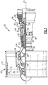
- FIG. 1 schematically illustrates a gas turbine engine 20.
- the gas turbine engine 20 is disclosed herein as a two-spool turbofan that generally incorporates a fan section 22, a compressor section 24, a combustor section 26 and a turbine section 28.
- Alternative engines might include an augmentor section (not shown) among other systems or features.
- the fan section 22 drives air along a bypass flow path B in a bypass duct defined within a nacelle 15, while the compressor section 24 drives air along a core flow path C for compression and communication into the combustor section 26 then expansion through the turbine section 28.
- the exemplary engine 20 generally includes a low speed spool 30 and a high speed spool 32 mounted for rotation about an engine central longitudinal axis A relative to an engine static structure 36 via several bearing systems 38. It should be understood that various bearing systems 38 at various locations may alternatively or additionally be provided, and the location of bearing systems 38 may be varied as appropriate to the application.
- the low speed spool 30 generally includes an inner shaft 40 that interconnects a fan 42, a first (or low) pressure compressor 44 and a first (or low) pressure turbine 46.
- the inner shaft 40 is connected to the fan 42 through a speed change mechanism, which in exemplary gas turbine engine 20 is illustrated as a geared architecture 48 to drive the fan 42 at a lower speed than the low speed spool 30.
- the high speed spool 32 includes an outer shaft 50 that interconnects a second (or high) pressure compressor 52 and a second (or high) pressure turbine 54.
- a combustor 56 is arranged in exemplary gas turbine 20 between the high pressure compressor 52 and the high pressure turbine 54.
- a mid-turbine frame 57 of the engine static structure 36 is arranged generally between the high pressure turbine 54 and the low pressure turbine 46.
- the mid-turbine frame 57 further supports bearing systems 38 in the turbine section 28.
- the inner shaft 40 and the outer shaft 50 are concentric and rotate via bearing systems 38 about the engine central longitudinal axis A which is collinear with their longitudinal axes.
- the core airflow is compressed by the low pressure compressor 44 then the high pressure compressor 52, mixed and burned with fuel in the combustor 56, then expanded over the high pressure turbine 54 and low pressure turbine 46.
- the mid-turbine frame 57 includes airfoils 59 which are in the core airflow path C.
- the turbines 46, 54 rotationally drive the respective low speed spool 30 and high speed spool 32 in response to the expansion.
- gear system 48 may be located aft of combustor section 26 or even aft of turbine section 28, and fan section 22 may be positioned forward or aft of the location of gear system 48.
- the engine 20 in one example is a high-bypass geared aircraft engine.
- the engine 20 bypass ratio is greater than about six, with an example embodiment being greater than about ten
- the geared architecture 48 is an epicyclic gear train, such as a planetary gear system or other gear system, with a gear reduction ratio of greater than about 2.3 and the low pressure turbine 46 has a pressure ratio that is greater than about five.
- the engine 20 bypass ratio is greater than about ten
- the fan diameter is significantly larger than that of the low pressure compressor 44
- the low pressure turbine 46 has a pressure ratio that is greater than about five.
- Low pressure turbine 46 pressure ratio is pressure measured prior to inlet of low pressure turbine 46 as related to the pressure at the outlet of the low pressure turbine 46 prior to an exhaust nozzle.
- the geared architecture 48 may be an epicycle gear train, such as a planetary gear system or other gear system, with a gear reduction ratio of greater than about 2.3:1. It should be understood, however, that the above parameters are only exemplary of one embodiment of a geared architecture engine and that the present invention is applicable to other gas turbine engines including direct drive turbofans.
- the fan section 22 of the engine 20 is designed for a particular flight condition -- typically cruise at about 0.8 Mach and about 35,000 feet (10,668 meters).
- the flight condition of 0.8 Mach and 35,000 ft (10,668 meters), with the engine at its best fuel consumption - also known as "bucket cruise Thrust Specific Fuel Consumption ('TSFC')" - is the industry standard parameter of lbm of fuel being burned divided by lbf of thrust the engine produces at that minimum point.
- "Low fan pressure ratio” is the pressure ratio across the fan blade alone, without a Fan Exit Guide Vane (“FEGV”) system.
- the low fan pressure ratio as disclosed herein according to one non-limiting embodiment is less than about 1.45.
- the "Low corrected fan tip speed” as disclosed herein according to one non-limiting embodiment is less than about 1150 ft / second (350.5 meters/second).
- Figure 2 schematically shows an engine 100 having a compressor 102 delivering cooling air into line 104 which passes through a heat exchanger 106, and to the turbine section 110 through a line 112.
- a combustor 108 is intermediate the compressor 102 and turbine section 110.
- the heat exchanger 106 may sit in the bypass duct, such as shown in the Figure 1 engine 20. Alternatively, the heat exchanger could be placed in other locations.
- known heat exchangers have difficulty achieving sufficient cooling.
- known heat exchangers face challenges and, in particular, with regard to stresses that are placed on particular areas of the heat exchanger through thermal gradients.
- FIG 3A shows a heat exchanger 106.
- an area 114 may be defined adjacent a most extreme portion of the heat exchanger wherein a cool inlet 116 is entering the heat exchanger and moving through passages 117 to a cooling fluid outlet 118.
- Crossing across the flow path 117 is a hot inlet 120 leading to hot air passages 122 into the outlet 124.
- it is the air in lines 104 and 112 which is entering at 120 and leaving at 124. It may be the bypass air or other cooling air which enters inlet 116 and leaves outlet 118.
- the section 114 formed at the edges or corner of the heat exchanger 106 sees the greatest difference between the high temperature of the hot inlet and the low temperature of the cool inlet 116. This is because they are both at their most upstream positions. Thus, the stresses in the area 114 are at the highest across the entire heat exchanger 106. It should be understood that the fluid flows along the entire surface faces of heat exchanger 106. However, this application focuses on section 114.
- FIG. 3B shows a prior art heat exchanger.
- the cooling passages 92 are of a relatively constant cross-section, as are the passages 94 receiving the hot air to be cooled.
- Traditional heat exchangers have been manufactured utilizing constant cross-sectional areas, sizes, and shapes.
- the cross-sectional area of the passages has been relatively constant across the entire area of the heat exchanger.
- Figure 4A shows a heat exchanger 125 and, in particular, the corner 114 as set forth in Figure 3A .
- the passages 128 and 130 are formed to be circular in cross-section.
- the passages 134 can be formed to be hexagonal or other polygonal or other shapes. As can be appreciated, there is a good deal more flow cross-sectional area in the passages 134 than in passages 128 and 130.
- the wall 136 between adjacent passages 134 and 130 is relatively small and, thus, there is a greater flow area than closer to the corner 126.
- the specific shape may be designed and tailored to maximize the efficiency of the heat exchanger.
- ends 139 of the passages 138 may extend into the cooling flow passages 117.
- the passages 117 would also include a plurality of spaced passages, and smaller passages, and a lower cross-sectional area of passages adjacent to corner 126. That is, the passages 117 might look much like the passages 128, 130, 134, and 138.
- a first plurality of passages could be said to extend in a first direction and to receive a first fluid and a second plurality of passages extending in a second direction, and to receive a second fluid.
- the first plurality of passages is formed across a cross-sectional face F 1 of the heat exchanger, and there being distinct combined flow cross-sectional areas of the first plurality of passages in different locations A/B across the cross-sectional face of the heat exchanger.
- the corner 126 is defined at an upstream end of the first set of passages and the second set of passages, and the combined flow cross-sectional areas of the first and second passages are less adjacent the corner than at locations spaced from the corner.
- a second plurality of passages 117 is formed across a cross-sectional face F 2 of the heat exchanger and there being distinct combined flow cross-sectional areas 117C / 117S of the second plurality of passages in different locations A/C across the cross-sectional face of the heat exchanger. As is clear, again closer to corner 126 there is less combined flow cross-sectional area.
- a fluid diameter of the passages in the passages adjacent to the corner is also less than a fluid diameter of the passages spaced further from the corner.
- the heat exchanger 125 may be formed by precision casting techniques.
- a casting technique known as investment casting of refractory metal core may be utilized.
- Tungsten and other refractory metals may be utilized in a so-called lost metal technique to form the internal passages.
- Figure 5 schematically shows an additive manufacturing technique wherein an intermediate portion 150 of a flow passage is being formed by an additive manufacturing tool 152.
- additive manufacturing builds up a part by placing material down in layers. Additive manufacturing is able to make very complex shapes.
- FIG. 3A The arrangement shown in Figure 3A is a so-called cross-flow heat exchanger wherein the two fluids cross each other and along generally perpendicular directions.
Landscapes
- Engineering & Computer Science (AREA)
- Mechanical Engineering (AREA)
- General Engineering & Computer Science (AREA)
- Physics & Mathematics (AREA)
- Thermal Sciences (AREA)
- Chemical & Material Sciences (AREA)
- Combustion & Propulsion (AREA)
- Geometry (AREA)
- Turbine Rotor Nozzle Sealing (AREA)
Abstract
Description
- This application relates to a heat exchanger having a unique arrangement of its flow passages.
- Heat exchangers are utilized in any number of applications and serve to cool one fluid typically by exchanging heat with a secondary fluid. Historically, heat exchangers have been formed of flow channels which have a relatively constant cross-section, and which also provide a relatively constant flow area per unit of total area.
- One application for a heat exchanger is in a gas turbine engine. In gas turbine engines, a fan delivers air into a compressor and into a bypass duct as propulsion air. The air from the compressor is compressed and delivered into a combustor where it is mixed with fuel and ignited. Products of this combustion pass downstream over turbine rotors, driving them to rotate.
- The turbine section becomes quite hot and, thus, it is known to provide cooling air to the turbine section.
- With recent advances in gas turbine engines, the turbine is exposed to hotter temperatures. Further, the turbine is exposed to higher pressures than in the past.
- Thus, the cooling air being supplied to the turbine must also have a corresponding increase in pressure. However, when a higher pressure air is tapped from the compressor, the temperature also increases.
- Thus, the cooling air must be cooled in a heat exchanger before being delivered to the turbine section. Known heat exchangers face challenges in providing adequate cooling.
- In an aspect, a heat exchanger has a first plurality of passages extending in a first direction and to receive a first fluid and a second plurality of passages extending in a second direction, and to receive a second fluid, and the first plurality of passages being formed across a cross-sectional face of the heat exchanger, and there being distinct combined flow cross-sectional areas of the first plurality of passages in different locations across the cross-sectional face of the heat exchanger.
- In an embodiment, the first and second directions are generally perpendicular to each other.
- In another embodiment according to any of the previous embodiments, a corner is defined at an upstream end of the first set of passages and the second set of passages, and the flow cross-sectional area of the first and second passages being less adjacent the corner than at locations spaced from the corner.
- In another embodiment according to any of the previous embodiments, a shape of the first flow passages adjacent the corner is distinct from a shape of the passages spaced from the corner.
- In another embodiment according to any of the previous embodiments, a cross-sectional area of the passages in the first plurality of passages adjacent to the corner is less than a cross-sectional area of the passages in the first plurality of passages spaced further from the corner.
- In another embodiment according to any of the previous embodiments, the passages in the first plurality of passages spaced from the corner include a polygonal shape.
- In another embodiment according to any of the previous embodiments, the passages in the first set of passages adjacent the corner having a cylindrical shape.
- In another embodiment according to any of the previous embodiments, a cross-sectional area of the passages in the first plurality of passages adjacent to the corner is less than a cross-sectional area of the passages in the first plurality of passages spaced further from the corner.
- In another embodiment according to any of the previous embodiments, the second plurality of passages being formed across a cross-sectional face of the heat exchanger and there also being distinct combined flow cross-sectional areas of the second plurality of passages in different locations across the cross-sectional face of the heat exchanger.
- In another aspect, a gas turbine engine has a compressor and a turbine section. A heat exchanger cools air delivered to the turbine section for cooling components in the turbine section, the heat exchanger including a first plurality of passages extending in a first direction and to receive a first fluid and a second plurality of passages extending in a second direction, and to receive a second fluid, and the first plurality of passages being formed across a cross-sectional face of the heat exchanger, and there being distinct combined flow cross-sectional areas of the first cooling passages in different locations across the cross-sectional face of the heat exchanger.
- In an embodiment, the first and second directions are generally perpendicular to each other.
- In another embodiment according to any of the previous embodiments, a corner is defined at an upstream end of the first set of passages and the second set of passages, and the combined flow cross-sectional area of the first and second passages being less adjacent the corner than at locations spaced from the corner.
- In another embodiment according to any of the previous embodiments, a shape of the first flow passages adjacent the corner is distinct from a shape of the passages spaced from the corner.
- In another embodiment according to any of the previous embodiments, a cross-sectional area of the passages in the first set of passages adjacent to the corner is less than a cross-sectional area of the passages and the first set of passages spaced further from the corner.
- In another embodiment according to any of the previous embodiments, the passages in the first plurality of passages spaced from the corner include a polygonal shape.
- In another embodiment according to any of the previous embodiments, the passages in the first set of passages adjacent the corner having a cylindrical shape.
- In another embodiment according to any of the previous embodiments, the second plurality of passages being formed across a cross-sectional face of the heat exchanger and there being distinct combined flow cross-sectional areas of the second plurality of passages in different locations across the cross-sectional face of the heat exchanger.
- In another aspect, a method of forming a heat exchanger includes forming a first plurality of passages extending in a first direction and to receive a first fluid and forming a second plurality of passages extending in a second direction, and to receive a second fluid, and the first plurality of passages being formed across a cross-sectional face of the heat exchanger, and there being distinct combined flow cross-sectional areas of the first cooling passages in different locations across the cross-sectional face of the heat exchanger.
- In an embodiment, the first and second plurality of passages are formed utilizing refractory metal cores.
- In another embodiment according to any of the previous embodiments, the heat exchanger is formed using an additive manufacturing process.
- These and other features may be best understood from the following drawings and specification.
-
-
Figure 1 schematically shows a gas turbine engine. -
Figure 2 is a highly schematic view of a cooling flow in a gas turbine engine. -
Figure 3A schematically shows a heat exchanger embodiment. -
Figure 3B shows a portion ofFigure 3A in the prior art. -
Figure 4A shows a disclosed heat exchanger at the same portion ofFigure 3B . -
Figure 4B shows another detail of the heat exchanger embodiment ofFigures 3A-3B ,4A-4B µ. -
Figure 5 shows a manufacturing step. -
Figure 1 schematically illustrates agas turbine engine 20. Thegas turbine engine 20 is disclosed herein as a two-spool turbofan that generally incorporates afan section 22, acompressor section 24, a combustor section 26 and aturbine section 28. Alternative engines might include an augmentor section (not shown) among other systems or features. Thefan section 22 drives air along a bypass flow path B in a bypass duct defined within anacelle 15, while thecompressor section 24 drives air along a core flow path C for compression and communication into the combustor section 26 then expansion through theturbine section 28. Although depicted as a two-spool turbofan gas turbine engine in the disclosed non-limiting embodiment, it should be understood that the concepts described herein are not limited to use with two-spool turbofans as the teachings may be applied to other types of turbine engines including three-spool architectures. - The
exemplary engine 20 generally includes alow speed spool 30 and ahigh speed spool 32 mounted for rotation about an engine central longitudinal axis A relative to an enginestatic structure 36 viaseveral bearing systems 38. It should be understood thatvarious bearing systems 38 at various locations may alternatively or additionally be provided, and the location ofbearing systems 38 may be varied as appropriate to the application. - The
low speed spool 30 generally includes aninner shaft 40 that interconnects afan 42, a first (or low)pressure compressor 44 and a first (or low)pressure turbine 46. Theinner shaft 40 is connected to thefan 42 through a speed change mechanism, which in exemplarygas turbine engine 20 is illustrated as a gearedarchitecture 48 to drive thefan 42 at a lower speed than thelow speed spool 30. Thehigh speed spool 32 includes anouter shaft 50 that interconnects a second (or high)pressure compressor 52 and a second (or high)pressure turbine 54. Acombustor 56 is arranged inexemplary gas turbine 20 between thehigh pressure compressor 52 and thehigh pressure turbine 54. Amid-turbine frame 57 of the enginestatic structure 36 is arranged generally between thehigh pressure turbine 54 and thelow pressure turbine 46. Themid-turbine frame 57 further supports bearingsystems 38 in theturbine section 28. Theinner shaft 40 and theouter shaft 50 are concentric and rotate viabearing systems 38 about the engine central longitudinal axis A which is collinear with their longitudinal axes. - The core airflow is compressed by the
low pressure compressor 44 then thehigh pressure compressor 52, mixed and burned with fuel in thecombustor 56, then expanded over thehigh pressure turbine 54 andlow pressure turbine 46. Themid-turbine frame 57 includesairfoils 59 which are in the core airflow path C. Theturbines low speed spool 30 andhigh speed spool 32 in response to the expansion. It will be appreciated that each of the positions of thefan section 22,compressor section 24, combustor section 26,turbine section 28, and fandrive gear system 48 may be varied. For example,gear system 48 may be located aft of combustor section 26 or even aft ofturbine section 28, andfan section 22 may be positioned forward or aft of the location ofgear system 48. - The
engine 20 in one example is a high-bypass geared aircraft engine. In a further example, theengine 20 bypass ratio is greater than about six, with an example embodiment being greater than about ten, the gearedarchitecture 48 is an epicyclic gear train, such as a planetary gear system or other gear system, with a gear reduction ratio of greater than about 2.3 and thelow pressure turbine 46 has a pressure ratio that is greater than about five. In one disclosed embodiment, theengine 20 bypass ratio is greater than about ten, the fan diameter is significantly larger than that of thelow pressure compressor 44, and thelow pressure turbine 46 has a pressure ratio that is greater than about five.Low pressure turbine 46 pressure ratio is pressure measured prior to inlet oflow pressure turbine 46 as related to the pressure at the outlet of thelow pressure turbine 46 prior to an exhaust nozzle. The gearedarchitecture 48 may be an epicycle gear train, such as a planetary gear system or other gear system, with a gear reduction ratio of greater than about 2.3:1. It should be understood, however, that the above parameters are only exemplary of one embodiment of a geared architecture engine and that the present invention is applicable to other gas turbine engines including direct drive turbofans. - A significant amount of thrust is provided by the bypass flow B due to the high bypass ratio. The
fan section 22 of theengine 20 is designed for a particular flight condition -- typically cruise at about 0.8 Mach and about 35,000 feet (10,668 meters). The flight condition of 0.8 Mach and 35,000 ft (10,668 meters), with the engine at its best fuel consumption - also known as "bucket cruise Thrust Specific Fuel Consumption ('TSFC')" - is the industry standard parameter of lbm of fuel being burned divided by lbf of thrust the engine produces at that minimum point. "Low fan pressure ratio" is the pressure ratio across the fan blade alone, without a Fan Exit Guide Vane ("FEGV") system. The low fan pressure ratio as disclosed herein according to one non-limiting embodiment is less than about 1.45. "Low corrected fan tip speed" is the actual fan tip speed in ft/sec divided by an industry standard temperature correction of [(Tram °R) / (518.7 °R)]0.5 (where °R = K x 9/5). The "Low corrected fan tip speed" as disclosed herein according to one non-limiting embodiment is less than about 1150 ft / second (350.5 meters/second). -
Figure 2 schematically shows anengine 100 having acompressor 102 delivering cooling air into line 104 which passes through aheat exchanger 106, and to theturbine section 110 through a line 112. As known, acombustor 108 is intermediate thecompressor 102 andturbine section 110. - The
heat exchanger 106 may sit in the bypass duct, such as shown in theFigure 1 engine 20. Alternatively, the heat exchanger could be placed in other locations. - As mentioned above, it is desirable to cool the compressed air being delivered to the turbine section as cooling air in the
heat exchanger 106, however, known heat exchangers have difficulty achieving sufficient cooling. In addition, known heat exchangers face challenges and, in particular, with regard to stresses that are placed on particular areas of the heat exchanger through thermal gradients. -
Figure 3A shows aheat exchanger 106. As shown, anarea 114 may be defined adjacent a most extreme portion of the heat exchanger wherein acool inlet 116 is entering the heat exchanger and moving throughpassages 117 to a coolingfluid outlet 118. Crossing across theflow path 117 is ahot inlet 120 leading tohot air passages 122 into theoutlet 124. In the arrangement shown inFigure 2 , it is the air in lines 104 and 112 which is entering at 120 and leaving at 124. It may be the bypass air or other cooling air which entersinlet 116 and leavesoutlet 118. - The
section 114 formed at the edges or corner of theheat exchanger 106 sees the greatest difference between the high temperature of the hot inlet and the low temperature of thecool inlet 116. This is because they are both at their most upstream positions. Thus, the stresses in thearea 114 are at the highest across theentire heat exchanger 106. It should be understood that the fluid flows along the entire surface faces ofheat exchanger 106. However, this application focuses onsection 114. -
Figure 3B shows a prior art heat exchanger. Thecooling passages 92 are of a relatively constant cross-section, as are thepassages 94 receiving the hot air to be cooled. Traditional heat exchangers have been manufactured utilizing constant cross-sectional areas, sizes, and shapes. In addition, the cross-sectional area of the passages has been relatively constant across the entire area of the heat exchanger. -
Figure 4A shows aheat exchanger 125 and, in particular, thecorner 114 as set forth inFigure 3A . As shown, adjacent thecorner 126 discussed above, there is a verysmall passage 128 and then a somewhatlarger passage 130. Thepassages corner 126, thepassages 134 can be formed to be hexagonal or other polygonal or other shapes. As can be appreciated, there is a good deal more flow cross-sectional area in thepassages 134 than inpassages wall 136 betweenadjacent passages corner 126. In addition, the specific shape may be designed and tailored to maximize the efficiency of the heat exchanger. - As also shown, ends 139 of the
passages 138 may extend into the coolingflow passages 117. Although not clear from this figure, thepassages 117 would also include a plurality of spaced passages, and smaller passages, and a lower cross-sectional area of passages adjacent to corner 126. That is, thepassages 117 might look much like thepassages - In the heat exchanger of
Figure 4A , a first plurality of passages could be said to extend in a first direction and to receive a first fluid and a second plurality of passages extending in a second direction, and to receive a second fluid. The first plurality of passages is formed across a cross-sectional face F1 of the heat exchanger, and there being distinct combined flow cross-sectional areas of the first plurality of passages in different locations A/B across the cross-sectional face of the heat exchanger. Thecorner 126 is defined at an upstream end of the first set of passages and the second set of passages, and the combined flow cross-sectional areas of the first and second passages are less adjacent the corner than at locations spaced from the corner. - As shown in
Figure 4B , a second plurality ofpassages 117 is formed across a cross-sectional face F2 of the heat exchanger and there being distinct combined flowcross-sectional areas 117C / 117S of the second plurality of passages in different locations A/C across the cross-sectional face of the heat exchanger. As is clear, again closer to corner 126 there is less combined flow cross-sectional area. - A fluid diameter of the passages in the passages adjacent to the corner is also less than a fluid diameter of the passages spaced further from the corner.
- The
heat exchanger 125 may be formed by precision casting techniques. As an example, a casting technique known as investment casting of refractory metal core may be utilized. Tungsten and other refractory metals may be utilized in a so-called lost metal technique to form the internal passages. - Thus, the complex shapes and inter-fitting flow passages, as disclosed above, may be achieved with this method.
- An alternative manufacturing method is shown schematically in
Figure 5. Figure 5 schematically shows an additive manufacturing technique wherein anintermediate portion 150 of a flow passage is being formed by anadditive manufacturing tool 152. As known, additive manufacturing builds up a part by placing material down in layers. Additive manufacturing is able to make very complex shapes. - Any type of additive manufacturing process may be utilized. A worker of ordinary skill in the art would be able to select an appropriate known additive manufacturing process based upon the goals of this disclosure.
- Thus, utilizing precision casting or additive manufacturing techniques, a worker of ordinary skill in the art would be able to achieve specific arrangements of inter-fitting flow passages as desired for a particular heat exchanger application.
- The arrangement shown in
Figure 3A is a so-called cross-flow heat exchanger wherein the two fluids cross each other and along generally perpendicular directions. - Although an embodiment of this invention has been disclosed, a worker of ordinary skill in this art would recognize that certain modifications would come within the scope of this invention. For that reason, the following claims should be studied to determine the true scope and content of this invention.
Claims (12)
- A heat exchanger (106) comprising:a first plurality of passages (128, 130, 134, 138) extending in a first direction and to receive a first fluid and a second plurality of passages (117) extending in a second direction, and to receive a second fluid, said first plurality of passages (128... 138) being formed across a first cross-sectional face (F1) of the heat exchanger (106), and there being distinct combined flow cross-sectional areas of said first plurality of passages (128...138) in different locations across said first cross-sectional face (F1) of said heat exchanger (106).
- The heat exchanger (106) as set forth in claim 1, wherein said first and second directions are generally perpendicular to each other.
- The heat exchanger (106) as set forth in claim 1 or 2, wherein a corner (126) is defined at an upstream end of said first plurality of passages (128...138) and said second plurality of passages (117), and a flow cross-sectional area of said first and second pluralities of passages being less adjacent said corner (126) than at locations spaced from said corner.
- The heat exchanger (106) as set forth in claim 3, wherein a shape of passages (128, 130) in said plurality of first flow passages adjacent said corner (126) is distinct from a shape of passages (134, 138) in said first flow passages spaced from said corner (126).
- The heat exchanger (106) as set forth in claim 3 or 4, wherein a cross-sectional area of passages (128, 130) in said first plurality of passages adjacent to said corner (126) is less than a cross-sectional area of said passages (134, 138) in said first plurality of passages spaced further from said corner (126).
- The heat exchanger (106) as set forth in claim 3, 4 or 5, wherein said passages (134, 138) in said first plurality of passages spaced from said corner (126) include a polygonal shape.
- The heat exchanger (106) as set forth in any of claims 3 to 6, wherein said passages (128, 130) in said first plurality of passages adjacent said corner (126) have a cylindrical shape.
- The heat exchanger (106) as set forth in any preceding claim, wherein said second plurality of passages (117) are formed across a second cross-sectional face (F2) of the heat exchanger (106) and there also being distinct combined flow cross-sectional areas of said second plurality of passages (117) in different locations across said second cross-sectional face (F2) of said heat exchanger (106).
- A gas turbine engine (20) comprising:a compressor (24) and a turbine section (28); andthe heat exchanger (106) of any preceding claim, configured to cool air being delivered to said turbine section (28) for cooling components in said turbine section (28).
- A method of forming a heat exchanger (106) comprising:forming a first plurality of passages (128, 130, 134, 138) extending in a first direction and to receive a first fluid and forming a second plurality of passages (117) extending in a second direction, and to receive a second fluid, and said first plurality of passages (128...138) being formed across a first cross-sectional face (F1) of the heat exchanger (106), and there being distinct combined flow cross-sectional areas of said first cooling passages (128...138) in different locations across said first cross-sectional face (F1) of said heat exchanger (106).
- The method as set forth in claim 10, wherein said first and second plurality of passages are formed utilizing refractory metal cores.
- The method as set forth in claim 10, wherein said heat exchanger (106) is formed using an additive manufacturing process.
Applications Claiming Priority (1)
| Application Number | Priority Date | Filing Date | Title |
|---|---|---|---|
| US15/156,367 US10378359B2 (en) | 2016-05-17 | 2016-05-17 | Heat exchanger with precision manufactured flow passages |
Publications (2)
| Publication Number | Publication Date |
|---|---|
| EP3252420A1 true EP3252420A1 (en) | 2017-12-06 |
| EP3252420B1 EP3252420B1 (en) | 2020-08-19 |
Family
ID=58715059
Family Applications (1)
| Application Number | Title | Priority Date | Filing Date |
|---|---|---|---|
| EP17171560.0A Active EP3252420B1 (en) | 2016-05-17 | 2017-05-17 | Heat exchanger with precision manufactured flow passages |
Country Status (2)
| Country | Link |
|---|---|
| US (1) | US10378359B2 (en) |
| EP (1) | EP3252420B1 (en) |
Families Citing this family (6)
| Publication number | Priority date | Publication date | Assignee | Title |
|---|---|---|---|---|
| WO2018045327A1 (en) * | 2016-09-01 | 2018-03-08 | Additive Rocket Corporation | Structural heat exchanger |
| US11879691B2 (en) * | 2017-06-12 | 2024-01-23 | General Electric Company | Counter-flow heat exchanger |
| US11213923B2 (en) | 2018-07-13 | 2022-01-04 | General Electric Company | Heat exchangers having a three-dimensional lattice structure with a rounded unit cell entrance and methods of forming rounded unit cell entrances in a three-dimensional lattice structure of a heat exchanger |
| US10955200B2 (en) | 2018-07-13 | 2021-03-23 | General Electric Company | Heat exchangers having a three-dimensional lattice structure with baffle cells and methods of forming baffles in a three-dimensional lattice structure of a heat exchanger |
| US11333452B2 (en) | 2019-12-16 | 2022-05-17 | Hamilton Sundstrand Corporation | Conformal heat exchanger passage features for improved flow distribution |
| US11555659B2 (en) | 2020-12-18 | 2023-01-17 | Hamilton Sundstrand Corporation | Multi-scale heat exchanger core |
Citations (4)
| Publication number | Priority date | Publication date | Assignee | Title |
|---|---|---|---|---|
| US20030235494A1 (en) * | 2002-06-19 | 2003-12-25 | Draper Samuel David | Linked, manufacturable, non-plugging microcircuits |
| US20040035562A1 (en) * | 2002-07-12 | 2004-02-26 | Haruyuki Nishijima | Heat exchanger for cooling air |
| US20140140829A1 (en) * | 2012-11-16 | 2014-05-22 | United Technologies Corporation | Turbine engine cooling system with an open loop circuit |
| EP2871433A1 (en) * | 2013-11-06 | 2015-05-13 | BAE Systems PLC | Heat exchangers and the production thereof |
Family Cites Families (9)
| Publication number | Priority date | Publication date | Assignee | Title |
|---|---|---|---|---|
| US3863451A (en) * | 1972-10-06 | 1975-02-04 | Maschf Augsburg Nuernberg Ag | Heater apparatus of a hot gas external combustion piston engine |
| US7203064B2 (en) | 2003-12-12 | 2007-04-10 | Intel Corporation | Heat exchanger with cooling channels having varying geometry |
| US7814966B2 (en) | 2007-02-05 | 2010-10-19 | Gm Global Technology Operations, Inc. | Variable flow heat exchanger system and method |
| WO2008150806A1 (en) * | 2007-05-31 | 2008-12-11 | Amerifab, Inc. | Adjustable heat exchange apparatus and method of use |
| WO2011115883A2 (en) * | 2010-03-15 | 2011-09-22 | The Trustees Of Dartmouth College | Geometry of heat exchanger with high efficiency |
| US9010130B2 (en) | 2011-12-16 | 2015-04-21 | Linde Aktiengesellschaft | Variable surface area heat exchanger |
| JP6040633B2 (en) * | 2012-08-23 | 2016-12-07 | ダイキン工業株式会社 | Air conditioner heat exchanger |
| US10018052B2 (en) * | 2012-12-28 | 2018-07-10 | United Technologies Corporation | Gas turbine engine component having engineered vascular structure |
| JP2015014397A (en) * | 2013-07-04 | 2015-01-22 | パナソニック株式会社 | Heat exchanger |
-
2016
- 2016-05-17 US US15/156,367 patent/US10378359B2/en active Active
-
2017
- 2017-05-17 EP EP17171560.0A patent/EP3252420B1/en active Active
Patent Citations (4)
| Publication number | Priority date | Publication date | Assignee | Title |
|---|---|---|---|---|
| US20030235494A1 (en) * | 2002-06-19 | 2003-12-25 | Draper Samuel David | Linked, manufacturable, non-plugging microcircuits |
| US20040035562A1 (en) * | 2002-07-12 | 2004-02-26 | Haruyuki Nishijima | Heat exchanger for cooling air |
| US20140140829A1 (en) * | 2012-11-16 | 2014-05-22 | United Technologies Corporation | Turbine engine cooling system with an open loop circuit |
| EP2871433A1 (en) * | 2013-11-06 | 2015-05-13 | BAE Systems PLC | Heat exchangers and the production thereof |
Also Published As
| Publication number | Publication date |
|---|---|
| US10378359B2 (en) | 2019-08-13 |
| EP3252420B1 (en) | 2020-08-19 |
| US20170335689A1 (en) | 2017-11-23 |
Similar Documents
| Publication | Publication Date | Title |
|---|---|---|
| US11421598B2 (en) | Staggered heat exchanger array with side curtains | |
| EP3252420B1 (en) | Heat exchanger with precision manufactured flow passages | |
| EP2975217B1 (en) | Using inserts to balance heat transfer and stress in high temperature alloys | |
| EP3889535B1 (en) | Duct mounted heat exchanger | |
| EP2935833B1 (en) | Gas turbine engine including a pre-diffuser heat exchanger | |
| EP2977555B1 (en) | Airfoil platform with cooling channels | |
| US10526916B2 (en) | Heat exchanger with heat resistant center body | |
| US10465542B2 (en) | Gas turbine engine turbine vane baffle and serpentine cooling passage | |
| EP3249340B1 (en) | Heat exchanger with decreased core cross-sectional area | |
| EP2985417A1 (en) | Gas turbine engine component and wall | |
| EP3078807B2 (en) | Cooling passages for a gas turbine engine component | |
| EP3805527B1 (en) | Cooled cooling air for blade air seal through outer chamber | |
| EP3112596A1 (en) | Gas turbine engine airfoil with bi-axial skin cooling passage and corresponding gas turbine engine | |
| EP3650648B1 (en) | Cooled gas turbine engine article | |
| US10968746B2 (en) | Serpentine turn cover for gas turbine stator vane assembly | |
| US10914178B2 (en) | Airfoils having tapered tip flag cavity and cores for forming the same | |
| US10815794B2 (en) | Baffle for components of gas turbine engines | |
| EP3418495B1 (en) | Gaspath component including minicore plenums |
Legal Events
| Date | Code | Title | Description |
|---|---|---|---|
| PUAI | Public reference made under article 153(3) epc to a published international application that has entered the european phase |
Free format text: ORIGINAL CODE: 0009012 |
|
| STAA | Information on the status of an ep patent application or granted ep patent |
Free format text: STATUS: THE APPLICATION HAS BEEN PUBLISHED |
|
| AK | Designated contracting states |
Kind code of ref document: A1 Designated state(s): AL AT BE BG CH CY CZ DE DK EE ES FI FR GB GR HR HU IE IS IT LI LT LU LV MC MK MT NL NO PL PT RO RS SE SI SK SM TR |
|
| AX | Request for extension of the european patent |
Extension state: BA ME |
|
| STAA | Information on the status of an ep patent application or granted ep patent |
Free format text: STATUS: REQUEST FOR EXAMINATION WAS MADE |
|
| 17P | Request for examination filed |
Effective date: 20180606 |
|
| RBV | Designated contracting states (corrected) |
Designated state(s): AL AT BE BG CH CY CZ DE DK EE ES FI FR GB GR HR HU IE IS IT LI LT LU LV MC MK MT NL NO PL PT RO RS SE SI SK SM TR |
|
| STAA | Information on the status of an ep patent application or granted ep patent |
Free format text: STATUS: EXAMINATION IS IN PROGRESS |
|
| 17Q | First examination report despatched |
Effective date: 20181023 |
|
| GRAP | Despatch of communication of intention to grant a patent |
Free format text: ORIGINAL CODE: EPIDOSNIGR1 |
|
| STAA | Information on the status of an ep patent application or granted ep patent |
Free format text: STATUS: GRANT OF PATENT IS INTENDED |
|
| INTG | Intention to grant announced |
Effective date: 20200228 |
|
| RIC1 | Information provided on ipc code assigned before grant |
Ipc: F28D 7/00 20060101ALI20200218BHEP Ipc: F28F 13/08 20060101ALI20200218BHEP Ipc: F28D 21/00 20060101ALN20200218BHEP Ipc: F28F 1/04 20060101ALN20200218BHEP Ipc: F28F 7/02 20060101AFI20200218BHEP |
|
| GRAS | Grant fee paid |
Free format text: ORIGINAL CODE: EPIDOSNIGR3 |
|
| GRAA | (expected) grant |
Free format text: ORIGINAL CODE: 0009210 |
|
| STAA | Information on the status of an ep patent application or granted ep patent |
Free format text: STATUS: THE PATENT HAS BEEN GRANTED |
|
| AK | Designated contracting states |
Kind code of ref document: B1 Designated state(s): AL AT BE BG CH CY CZ DE DK EE ES FI FR GB GR HR HU IE IS IT LI LT LU LV MC MK MT NL NO PL PT RO RS SE SI SK SM TR |
|
| REG | Reference to a national code |
Ref country code: CH Ref legal event code: EP |
|
| REG | Reference to a national code |
Ref country code: DE Ref legal event code: R096 Ref document number: 602017021785 Country of ref document: DE |
|
| REG | Reference to a national code |
Ref country code: AT Ref legal event code: REF Ref document number: 1304416 Country of ref document: AT Kind code of ref document: T Effective date: 20200915 |
|
| REG | Reference to a national code |
Ref country code: IE Ref legal event code: FG4D |
|
| REG | Reference to a national code |
Ref country code: LT Ref legal event code: MG4D |
|
| REG | Reference to a national code |
Ref country code: NL Ref legal event code: MP Effective date: 20200819 |
|
| PG25 | Lapsed in a contracting state [announced via postgrant information from national office to epo] |
Ref country code: GR Free format text: LAPSE BECAUSE OF FAILURE TO SUBMIT A TRANSLATION OF THE DESCRIPTION OR TO PAY THE FEE WITHIN THE PRESCRIBED TIME-LIMIT Effective date: 20201120 Ref country code: LT Free format text: LAPSE BECAUSE OF FAILURE TO SUBMIT A TRANSLATION OF THE DESCRIPTION OR TO PAY THE FEE WITHIN THE PRESCRIBED TIME-LIMIT Effective date: 20200819 Ref country code: SE Free format text: LAPSE BECAUSE OF FAILURE TO SUBMIT A TRANSLATION OF THE DESCRIPTION OR TO PAY THE FEE WITHIN THE PRESCRIBED TIME-LIMIT Effective date: 20200819 Ref country code: BG Free format text: LAPSE BECAUSE OF FAILURE TO SUBMIT A TRANSLATION OF THE DESCRIPTION OR TO PAY THE FEE WITHIN THE PRESCRIBED TIME-LIMIT Effective date: 20201119 Ref country code: HR Free format text: LAPSE BECAUSE OF FAILURE TO SUBMIT A TRANSLATION OF THE DESCRIPTION OR TO PAY THE FEE WITHIN THE PRESCRIBED TIME-LIMIT Effective date: 20200819 Ref country code: NO Free format text: LAPSE BECAUSE OF FAILURE TO SUBMIT A TRANSLATION OF THE DESCRIPTION OR TO PAY THE FEE WITHIN THE PRESCRIBED TIME-LIMIT Effective date: 20201119 Ref country code: PT Free format text: LAPSE BECAUSE OF FAILURE TO SUBMIT A TRANSLATION OF THE DESCRIPTION OR TO PAY THE FEE WITHIN THE PRESCRIBED TIME-LIMIT Effective date: 20201221 Ref country code: FI Free format text: LAPSE BECAUSE OF FAILURE TO SUBMIT A TRANSLATION OF THE DESCRIPTION OR TO PAY THE FEE WITHIN THE PRESCRIBED TIME-LIMIT Effective date: 20200819 |
|
| REG | Reference to a national code |
Ref country code: AT Ref legal event code: MK05 Ref document number: 1304416 Country of ref document: AT Kind code of ref document: T Effective date: 20200819 |
|
| PG25 | Lapsed in a contracting state [announced via postgrant information from national office to epo] |
Ref country code: RS Free format text: LAPSE BECAUSE OF FAILURE TO SUBMIT A TRANSLATION OF THE DESCRIPTION OR TO PAY THE FEE WITHIN THE PRESCRIBED TIME-LIMIT Effective date: 20200819 Ref country code: LV Free format text: LAPSE BECAUSE OF FAILURE TO SUBMIT A TRANSLATION OF THE DESCRIPTION OR TO PAY THE FEE WITHIN THE PRESCRIBED TIME-LIMIT Effective date: 20200819 Ref country code: NL Free format text: LAPSE BECAUSE OF FAILURE TO SUBMIT A TRANSLATION OF THE DESCRIPTION OR TO PAY THE FEE WITHIN THE PRESCRIBED TIME-LIMIT Effective date: 20200819 Ref country code: PL Free format text: LAPSE BECAUSE OF FAILURE TO SUBMIT A TRANSLATION OF THE DESCRIPTION OR TO PAY THE FEE WITHIN THE PRESCRIBED TIME-LIMIT Effective date: 20200819 Ref country code: IS Free format text: LAPSE BECAUSE OF FAILURE TO SUBMIT A TRANSLATION OF THE DESCRIPTION OR TO PAY THE FEE WITHIN THE PRESCRIBED TIME-LIMIT Effective date: 20201219 |
|
| RAP2 | Party data changed (patent owner data changed or rights of a patent transferred) |
Owner name: RAYTHEON TECHNOLOGIES CORPORATION |
|
| PG25 | Lapsed in a contracting state [announced via postgrant information from national office to epo] |
Ref country code: RO Free format text: LAPSE BECAUSE OF FAILURE TO SUBMIT A TRANSLATION OF THE DESCRIPTION OR TO PAY THE FEE WITHIN THE PRESCRIBED TIME-LIMIT Effective date: 20200819 Ref country code: DK Free format text: LAPSE BECAUSE OF FAILURE TO SUBMIT A TRANSLATION OF THE DESCRIPTION OR TO PAY THE FEE WITHIN THE PRESCRIBED TIME-LIMIT Effective date: 20200819 Ref country code: CZ Free format text: LAPSE BECAUSE OF FAILURE TO SUBMIT A TRANSLATION OF THE DESCRIPTION OR TO PAY THE FEE WITHIN THE PRESCRIBED TIME-LIMIT Effective date: 20200819 Ref country code: EE Free format text: LAPSE BECAUSE OF FAILURE TO SUBMIT A TRANSLATION OF THE DESCRIPTION OR TO PAY THE FEE WITHIN THE PRESCRIBED TIME-LIMIT Effective date: 20200819 Ref country code: SM Free format text: LAPSE BECAUSE OF FAILURE TO SUBMIT A TRANSLATION OF THE DESCRIPTION OR TO PAY THE FEE WITHIN THE PRESCRIBED TIME-LIMIT Effective date: 20200819 |
|
| REG | Reference to a national code |
Ref country code: DE Ref legal event code: R097 Ref document number: 602017021785 Country of ref document: DE |
|
| PG25 | Lapsed in a contracting state [announced via postgrant information from national office to epo] |
Ref country code: AL Free format text: LAPSE BECAUSE OF FAILURE TO SUBMIT A TRANSLATION OF THE DESCRIPTION OR TO PAY THE FEE WITHIN THE PRESCRIBED TIME-LIMIT Effective date: 20200819 Ref country code: AT Free format text: LAPSE BECAUSE OF FAILURE TO SUBMIT A TRANSLATION OF THE DESCRIPTION OR TO PAY THE FEE WITHIN THE PRESCRIBED TIME-LIMIT Effective date: 20200819 Ref country code: ES Free format text: LAPSE BECAUSE OF FAILURE TO SUBMIT A TRANSLATION OF THE DESCRIPTION OR TO PAY THE FEE WITHIN THE PRESCRIBED TIME-LIMIT Effective date: 20200819 |
|
| PLBE | No opposition filed within time limit |
Free format text: ORIGINAL CODE: 0009261 |
|
| STAA | Information on the status of an ep patent application or granted ep patent |
Free format text: STATUS: NO OPPOSITION FILED WITHIN TIME LIMIT |
|
| PG25 | Lapsed in a contracting state [announced via postgrant information from national office to epo] |
Ref country code: SK Free format text: LAPSE BECAUSE OF FAILURE TO SUBMIT A TRANSLATION OF THE DESCRIPTION OR TO PAY THE FEE WITHIN THE PRESCRIBED TIME-LIMIT Effective date: 20200819 |
|
| 26N | No opposition filed |
Effective date: 20210520 |
|
| PG25 | Lapsed in a contracting state [announced via postgrant information from national office to epo] |
Ref country code: IT Free format text: LAPSE BECAUSE OF FAILURE TO SUBMIT A TRANSLATION OF THE DESCRIPTION OR TO PAY THE FEE WITHIN THE PRESCRIBED TIME-LIMIT Effective date: 20200819 |
|
| PG25 | Lapsed in a contracting state [announced via postgrant information from national office to epo] |
Ref country code: SI Free format text: LAPSE BECAUSE OF FAILURE TO SUBMIT A TRANSLATION OF THE DESCRIPTION OR TO PAY THE FEE WITHIN THE PRESCRIBED TIME-LIMIT Effective date: 20200819 |
|
| REG | Reference to a national code |
Ref country code: CH Ref legal event code: PL |
|
| PG25 | Lapsed in a contracting state [announced via postgrant information from national office to epo] |
Ref country code: LI Free format text: LAPSE BECAUSE OF NON-PAYMENT OF DUE FEES Effective date: 20210531 Ref country code: LU Free format text: LAPSE BECAUSE OF NON-PAYMENT OF DUE FEES Effective date: 20210517 Ref country code: MC Free format text: LAPSE BECAUSE OF FAILURE TO SUBMIT A TRANSLATION OF THE DESCRIPTION OR TO PAY THE FEE WITHIN THE PRESCRIBED TIME-LIMIT Effective date: 20200819 Ref country code: CH Free format text: LAPSE BECAUSE OF NON-PAYMENT OF DUE FEES Effective date: 20210531 |
|
| REG | Reference to a national code |
Ref country code: BE Ref legal event code: MM Effective date: 20210531 |
|
| PG25 | Lapsed in a contracting state [announced via postgrant information from national office to epo] |
Ref country code: IE Free format text: LAPSE BECAUSE OF NON-PAYMENT OF DUE FEES Effective date: 20210517 |
|
| PG25 | Lapsed in a contracting state [announced via postgrant information from national office to epo] |
Ref country code: BE Free format text: LAPSE BECAUSE OF NON-PAYMENT OF DUE FEES Effective date: 20210531 |
|
| PG25 | Lapsed in a contracting state [announced via postgrant information from national office to epo] |
Ref country code: HU Free format text: LAPSE BECAUSE OF FAILURE TO SUBMIT A TRANSLATION OF THE DESCRIPTION OR TO PAY THE FEE WITHIN THE PRESCRIBED TIME-LIMIT; INVALID AB INITIO Effective date: 20170517 |
|
| P01 | Opt-out of the competence of the unified patent court (upc) registered |
Effective date: 20230520 |
|
| PG25 | Lapsed in a contracting state [announced via postgrant information from national office to epo] |
Ref country code: CY Free format text: LAPSE BECAUSE OF FAILURE TO SUBMIT A TRANSLATION OF THE DESCRIPTION OR TO PAY THE FEE WITHIN THE PRESCRIBED TIME-LIMIT Effective date: 20200819 |
|
| PG25 | Lapsed in a contracting state [announced via postgrant information from national office to epo] |
Ref country code: MK Free format text: LAPSE BECAUSE OF FAILURE TO SUBMIT A TRANSLATION OF THE DESCRIPTION OR TO PAY THE FEE WITHIN THE PRESCRIBED TIME-LIMIT Effective date: 20200819 |
|
| PG25 | Lapsed in a contracting state [announced via postgrant information from national office to epo] |
Ref country code: TR Free format text: LAPSE BECAUSE OF FAILURE TO SUBMIT A TRANSLATION OF THE DESCRIPTION OR TO PAY THE FEE WITHIN THE PRESCRIBED TIME-LIMIT Effective date: 20200819 |
|
| PG25 | Lapsed in a contracting state [announced via postgrant information from national office to epo] |
Ref country code: MT Free format text: LAPSE BECAUSE OF FAILURE TO SUBMIT A TRANSLATION OF THE DESCRIPTION OR TO PAY THE FEE WITHIN THE PRESCRIBED TIME-LIMIT Effective date: 20200819 |
|
| PGFP | Annual fee paid to national office [announced via postgrant information from national office to epo] |
Ref country code: DE Payment date: 20250423 Year of fee payment: 9 |
|
| PGFP | Annual fee paid to national office [announced via postgrant information from national office to epo] |
Ref country code: GB Payment date: 20250423 Year of fee payment: 9 |
|
| PGFP | Annual fee paid to national office [announced via postgrant information from national office to epo] |
Ref country code: FR Payment date: 20250424 Year of fee payment: 9 |
|
| REG | Reference to a national code |
Ref country code: DE Ref legal event code: R081 Ref document number: 602017021785 Country of ref document: DE Owner name: RTX CORPORATION (N.D.GES.D. STAATES DELAWARE),, US Free format text: FORMER OWNER: UNITED TECHNOLOGIES CORPORATION, FARMINGTON, CONN., US |