EP3252293A1 - Secondary systems and methods of control for variable area fan nozzles - Google Patents
Secondary systems and methods of control for variable area fan nozzles Download PDFInfo
- Publication number
- EP3252293A1 EP3252293A1 EP17157241.5A EP17157241A EP3252293A1 EP 3252293 A1 EP3252293 A1 EP 3252293A1 EP 17157241 A EP17157241 A EP 17157241A EP 3252293 A1 EP3252293 A1 EP 3252293A1
- Authority
- EP
- European Patent Office
- Prior art keywords
- nozzle
- gas turbine
- turbine engine
- vafn
- engine
- Prior art date
- Legal status (The legal status is an assumption and is not a legal conclusion. Google has not performed a legal analysis and makes no representation as to the accuracy of the status listed.)
- Granted
Links
Images





Classifications
-
- F—MECHANICAL ENGINEERING; LIGHTING; HEATING; WEAPONS; BLASTING
- F02—COMBUSTION ENGINES; HOT-GAS OR COMBUSTION-PRODUCT ENGINE PLANTS
- F02K—JET-PROPULSION PLANTS
- F02K1/00—Plants characterised by the form or arrangement of the jet pipe or nozzle; Jet pipes or nozzles peculiar thereto
- F02K1/06—Varying effective area of jet pipe or nozzle
- F02K1/15—Control or regulation
- F02K1/18—Control or regulation automatic
-
- F—MECHANICAL ENGINEERING; LIGHTING; HEATING; WEAPONS; BLASTING
- F02—COMBUSTION ENGINES; HOT-GAS OR COMBUSTION-PRODUCT ENGINE PLANTS
- F02C—GAS-TURBINE PLANTS; AIR INTAKES FOR JET-PROPULSION PLANTS; CONTROLLING FUEL SUPPLY IN AIR-BREATHING JET-PROPULSION PLANTS
- F02C9/00—Controlling gas-turbine plants; Controlling fuel supply in air- breathing jet-propulsion plants
- F02C9/16—Control of working fluid flow
-
- F—MECHANICAL ENGINEERING; LIGHTING; HEATING; WEAPONS; BLASTING
- F04—POSITIVE - DISPLACEMENT MACHINES FOR LIQUIDS; PUMPS FOR LIQUIDS OR ELASTIC FLUIDS
- F04D—NON-POSITIVE-DISPLACEMENT PUMPS
- F04D29/00—Details, component parts, or accessories
- F04D29/40—Casings; Connections of working fluid
- F04D29/52—Casings; Connections of working fluid for axial pumps
- F04D29/54—Fluid-guiding means, e.g. diffusers
- F04D29/56—Fluid-guiding means, e.g. diffusers adjustable
- F04D29/563—Fluid-guiding means, e.g. diffusers adjustable specially adapted for elastic fluid pumps
-
- B—PERFORMING OPERATIONS; TRANSPORTING
- B64—AIRCRAFT; AVIATION; COSMONAUTICS
- B64D—EQUIPMENT FOR FITTING IN OR TO AIRCRAFT; FLIGHT SUITS; PARACHUTES; ARRANGEMENT OR MOUNTING OF POWER PLANTS OR PROPULSION TRANSMISSIONS IN AIRCRAFT
- B64D27/00—Arrangement or mounting of power plants in aircraft; Aircraft characterised by the type or position of power plants
- B64D27/02—Aircraft characterised by the type or position of power plants
- B64D27/10—Aircraft characterised by the type or position of power plants of gas-turbine type
-
- B—PERFORMING OPERATIONS; TRANSPORTING
- B64—AIRCRAFT; AVIATION; COSMONAUTICS
- B64D—EQUIPMENT FOR FITTING IN OR TO AIRCRAFT; FLIGHT SUITS; PARACHUTES; ARRANGEMENT OR MOUNTING OF POWER PLANTS OR PROPULSION TRANSMISSIONS IN AIRCRAFT
- B64D45/00—Aircraft indicators or protectors not otherwise provided for
-
- F—MECHANICAL ENGINEERING; LIGHTING; HEATING; WEAPONS; BLASTING
- F01—MACHINES OR ENGINES IN GENERAL; ENGINE PLANTS IN GENERAL; STEAM ENGINES
- F01D—NON-POSITIVE DISPLACEMENT MACHINES OR ENGINES, e.g. STEAM TURBINES
- F01D21/00—Shutting-down of machines or engines, e.g. in emergency; Regulating, controlling, or safety means not otherwise provided for
- F01D21/003—Arrangements for testing or measuring
-
- F—MECHANICAL ENGINEERING; LIGHTING; HEATING; WEAPONS; BLASTING
- F01—MACHINES OR ENGINES IN GENERAL; ENGINE PLANTS IN GENERAL; STEAM ENGINES
- F01D—NON-POSITIVE DISPLACEMENT MACHINES OR ENGINES, e.g. STEAM TURBINES
- F01D25/00—Component parts, details, or accessories, not provided for in, or of interest apart from, other groups
- F01D25/24—Casings; Casing parts, e.g. diaphragms, casing fastenings
-
- F—MECHANICAL ENGINEERING; LIGHTING; HEATING; WEAPONS; BLASTING
- F02—COMBUSTION ENGINES; HOT-GAS OR COMBUSTION-PRODUCT ENGINE PLANTS
- F02C—GAS-TURBINE PLANTS; AIR INTAKES FOR JET-PROPULSION PLANTS; CONTROLLING FUEL SUPPLY IN AIR-BREATHING JET-PROPULSION PLANTS
- F02C9/00—Controlling gas-turbine plants; Controlling fuel supply in air- breathing jet-propulsion plants
- F02C9/16—Control of working fluid flow
- F02C9/20—Control of working fluid flow by throttling; by adjusting vanes
-
- F—MECHANICAL ENGINEERING; LIGHTING; HEATING; WEAPONS; BLASTING
- F02—COMBUSTION ENGINES; HOT-GAS OR COMBUSTION-PRODUCT ENGINE PLANTS
- F02K—JET-PROPULSION PLANTS
- F02K1/00—Plants characterised by the form or arrangement of the jet pipe or nozzle; Jet pipes or nozzles peculiar thereto
- F02K1/06—Varying effective area of jet pipe or nozzle
- F02K1/12—Varying effective area of jet pipe or nozzle by means of pivoted flaps
-
- F—MECHANICAL ENGINEERING; LIGHTING; HEATING; WEAPONS; BLASTING
- F02—COMBUSTION ENGINES; HOT-GAS OR COMBUSTION-PRODUCT ENGINE PLANTS
- F02K—JET-PROPULSION PLANTS
- F02K1/00—Plants characterised by the form or arrangement of the jet pipe or nozzle; Jet pipes or nozzles peculiar thereto
- F02K1/06—Varying effective area of jet pipe or nozzle
- F02K1/15—Control or regulation
-
- F—MECHANICAL ENGINEERING; LIGHTING; HEATING; WEAPONS; BLASTING
- F02—COMBUSTION ENGINES; HOT-GAS OR COMBUSTION-PRODUCT ENGINE PLANTS
- F02K—JET-PROPULSION PLANTS
- F02K3/00—Plants including a gas turbine driving a compressor or a ducted fan
- F02K3/02—Plants including a gas turbine driving a compressor or a ducted fan in which part of the working fluid by-passes the turbine and combustion chamber
- F02K3/04—Plants including a gas turbine driving a compressor or a ducted fan in which part of the working fluid by-passes the turbine and combustion chamber the plant including ducted fans, i.e. fans with high volume, low pressure outputs, for augmenting the jet thrust, e.g. of double-flow type
-
- F—MECHANICAL ENGINEERING; LIGHTING; HEATING; WEAPONS; BLASTING
- F04—POSITIVE - DISPLACEMENT MACHINES FOR LIQUIDS; PUMPS FOR LIQUIDS OR ELASTIC FLUIDS
- F04D—NON-POSITIVE-DISPLACEMENT PUMPS
- F04D27/00—Control, e.g. regulation, of pumps, pumping installations or pumping systems specially adapted for elastic fluids
- F04D27/002—Control, e.g. regulation, of pumps, pumping installations or pumping systems specially adapted for elastic fluids by varying geometry within the pumps, e.g. by adjusting vanes
-
- F—MECHANICAL ENGINEERING; LIGHTING; HEATING; WEAPONS; BLASTING
- F04—POSITIVE - DISPLACEMENT MACHINES FOR LIQUIDS; PUMPS FOR LIQUIDS OR ELASTIC FLUIDS
- F04D—NON-POSITIVE-DISPLACEMENT PUMPS
- F04D29/00—Details, component parts, or accessories
- F04D29/40—Casings; Connections of working fluid
- F04D29/52—Casings; Connections of working fluid for axial pumps
- F04D29/54—Fluid-guiding means, e.g. diffusers
- F04D29/541—Specially adapted for elastic fluid pumps
- F04D29/542—Bladed diffusers
-
- F—MECHANICAL ENGINEERING; LIGHTING; HEATING; WEAPONS; BLASTING
- F05—INDEXING SCHEMES RELATING TO ENGINES OR PUMPS IN VARIOUS SUBCLASSES OF CLASSES F01-F04
- F05D—INDEXING SCHEME FOR ASPECTS RELATING TO NON-POSITIVE-DISPLACEMENT MACHINES OR ENGINES, GAS-TURBINES OR JET-PROPULSION PLANTS
- F05D2220/00—Application
- F05D2220/30—Application in turbines
- F05D2220/32—Application in turbines in gas turbines
-
- F—MECHANICAL ENGINEERING; LIGHTING; HEATING; WEAPONS; BLASTING
- F05—INDEXING SCHEMES RELATING TO ENGINES OR PUMPS IN VARIOUS SUBCLASSES OF CLASSES F01-F04
- F05D—INDEXING SCHEME FOR ASPECTS RELATING TO NON-POSITIVE-DISPLACEMENT MACHINES OR ENGINES, GAS-TURBINES OR JET-PROPULSION PLANTS
- F05D2220/00—Application
- F05D2220/30—Application in turbines
- F05D2220/36—Application in turbines specially adapted for the fan of turbofan engines
-
- F—MECHANICAL ENGINEERING; LIGHTING; HEATING; WEAPONS; BLASTING
- F05—INDEXING SCHEMES RELATING TO ENGINES OR PUMPS IN VARIOUS SUBCLASSES OF CLASSES F01-F04
- F05D—INDEXING SCHEME FOR ASPECTS RELATING TO NON-POSITIVE-DISPLACEMENT MACHINES OR ENGINES, GAS-TURBINES OR JET-PROPULSION PLANTS
- F05D2240/00—Components
- F05D2240/10—Stators
- F05D2240/12—Fluid guiding means, e.g. vanes
- F05D2240/128—Nozzles
-
- F—MECHANICAL ENGINEERING; LIGHTING; HEATING; WEAPONS; BLASTING
- F05—INDEXING SCHEMES RELATING TO ENGINES OR PUMPS IN VARIOUS SUBCLASSES OF CLASSES F01-F04
- F05D—INDEXING SCHEME FOR ASPECTS RELATING TO NON-POSITIVE-DISPLACEMENT MACHINES OR ENGINES, GAS-TURBINES OR JET-PROPULSION PLANTS
- F05D2270/00—Control
- F05D2270/30—Control parameters, e.g. input parameters
- F05D2270/301—Pressure
-
- F—MECHANICAL ENGINEERING; LIGHTING; HEATING; WEAPONS; BLASTING
- F05—INDEXING SCHEMES RELATING TO ENGINES OR PUMPS IN VARIOUS SUBCLASSES OF CLASSES F01-F04
- F05D—INDEXING SCHEME FOR ASPECTS RELATING TO NON-POSITIVE-DISPLACEMENT MACHINES OR ENGINES, GAS-TURBINES OR JET-PROPULSION PLANTS
- F05D2270/00—Control
- F05D2270/30—Control parameters, e.g. input parameters
- F05D2270/301—Pressure
- F05D2270/3013—Outlet pressure
-
- F—MECHANICAL ENGINEERING; LIGHTING; HEATING; WEAPONS; BLASTING
- F05—INDEXING SCHEMES RELATING TO ENGINES OR PUMPS IN VARIOUS SUBCLASSES OF CLASSES F01-F04
- F05D—INDEXING SCHEME FOR ASPECTS RELATING TO NON-POSITIVE-DISPLACEMENT MACHINES OR ENGINES, GAS-TURBINES OR JET-PROPULSION PLANTS
- F05D2270/00—Control
- F05D2270/30—Control parameters, e.g. input parameters
- F05D2270/332—Maximum loads or fatigue criteria
-
- F—MECHANICAL ENGINEERING; LIGHTING; HEATING; WEAPONS; BLASTING
- F05—INDEXING SCHEMES RELATING TO ENGINES OR PUMPS IN VARIOUS SUBCLASSES OF CLASSES F01-F04
- F05D—INDEXING SCHEME FOR ASPECTS RELATING TO NON-POSITIVE-DISPLACEMENT MACHINES OR ENGINES, GAS-TURBINES OR JET-PROPULSION PLANTS
- F05D2270/00—Control
- F05D2270/30—Control parameters, e.g. input parameters
- F05D2270/334—Vibration measurements
-
- F—MECHANICAL ENGINEERING; LIGHTING; HEATING; WEAPONS; BLASTING
- F05—INDEXING SCHEMES RELATING TO ENGINES OR PUMPS IN VARIOUS SUBCLASSES OF CLASSES F01-F04
- F05D—INDEXING SCHEME FOR ASPECTS RELATING TO NON-POSITIVE-DISPLACEMENT MACHINES OR ENGINES, GAS-TURBINES OR JET-PROPULSION PLANTS
- F05D2270/00—Control
- F05D2270/60—Control system actuates means
- F05D2270/62—Electrical actuators
-
- F—MECHANICAL ENGINEERING; LIGHTING; HEATING; WEAPONS; BLASTING
- F05—INDEXING SCHEMES RELATING TO ENGINES OR PUMPS IN VARIOUS SUBCLASSES OF CLASSES F01-F04
- F05D—INDEXING SCHEME FOR ASPECTS RELATING TO NON-POSITIVE-DISPLACEMENT MACHINES OR ENGINES, GAS-TURBINES OR JET-PROPULSION PLANTS
- F05D2270/00—Control
- F05D2270/70—Type of control algorithm
- F05D2270/708—Type of control algorithm with comparison tables
-
- F—MECHANICAL ENGINEERING; LIGHTING; HEATING; WEAPONS; BLASTING
- F05—INDEXING SCHEMES RELATING TO ENGINES OR PUMPS IN VARIOUS SUBCLASSES OF CLASSES F01-F04
- F05D—INDEXING SCHEME FOR ASPECTS RELATING TO NON-POSITIVE-DISPLACEMENT MACHINES OR ENGINES, GAS-TURBINES OR JET-PROPULSION PLANTS
- F05D2270/00—Control
- F05D2270/70—Type of control algorithm
- F05D2270/709—Type of control algorithm with neural networks
-
- F—MECHANICAL ENGINEERING; LIGHTING; HEATING; WEAPONS; BLASTING
- F05—INDEXING SCHEMES RELATING TO ENGINES OR PUMPS IN VARIOUS SUBCLASSES OF CLASSES F01-F04
- F05D—INDEXING SCHEME FOR ASPECTS RELATING TO NON-POSITIVE-DISPLACEMENT MACHINES OR ENGINES, GAS-TURBINES OR JET-PROPULSION PLANTS
- F05D2270/00—Control
- F05D2270/70—Type of control algorithm
- F05D2270/71—Type of control algorithm synthesized, i.e. parameter computed by a mathematical model
-
- G—PHYSICS
- G01—MEASURING; TESTING
- G01H—MEASUREMENT OF MECHANICAL VIBRATIONS OR ULTRASONIC, SONIC OR INFRASONIC WAVES
- G01H9/00—Measuring mechanical vibrations or ultrasonic, sonic or infrasonic waves by using radiation-sensitive means, e.g. optical means
Definitions
- the present disclosure relates generally to variable area fan nozzles and, more particularly, to controlling nozzle areas of variable area fan nozzles.
- Bypass turbofan engines produce two exhaust flows, a core engine flow and a fan flow.
- the core engine flow is discharged from a core flow nozzle after passing through a core engine.
- the fan flow passes through an annular passageway formed by a nacelle surrounding the core engine and fan duct.
- the cross-sectional areas through which these two flows pass may be optimized for specific operating conditions, such as take-off, climb, cruise, etc.
- Variable area fan nozzles that include movable petals are used to enlarge or reduce the nozzle area of the fan flow, and thereby, decrease or increase the exhaust velocity, respectively.
- a control system for a variable area fan nozzle may have a plurality of petals and may be for use with a gas turbine engine.
- the control system may include a primary system configured to acquire primary data indicative of an operating condition of the VAFN, a secondary system configured to acquire secondary data indicative of a current operating condition of the gas turbine engine, and a control module in operative communication with the primary system and the secondary system.
- the control module may be configured to: determine a nozzle area of the VAFN based at least in part on the primary data, adjust the determined nozzle area based on the secondary data, and position the plurality of petals according to the adjusted nozzle area.
- the secondary data may include data indicative of a backpressure of the gas turbine engine.
- the secondary system may include at least one pressure sensor configured to determine the backpressure of the gas turbine engine.
- the at least one pressure sensor may be disposed proximate an aft end of a core engine nacelle of the gas turbine engine.
- the secondary data may include data indicative of a fan blade strain of the gas turbine engine.
- the secondary system may include at least one strain sensor configured to determine the fan blade strain of the gas turbine engine.
- the at least one strain sensor may include a fiber optic strain sensor disposed on a fan blade of the gas turbine engine.
- control module may be further configured to determine an operational transient of the gas turbine engine based on the secondary data.
- control module may be further configured to send a signal to alert aircraft crew members of the operational transient.
- control module may be further configured to move the plurality of petals to a failsafe position when the secondary data indicates the operational transient.
- an aircraft may include a gas turbine engine, a variable area fan nozzle (VAFN) mounted to a downstream end of the gas turbine engine, the VAFN including a plurality of petals and at least one actuator configured to move the plurality of petals, and a control system in operative communication with the gas turbine engine and the VAFN.
- the control system may include at least one pressure sensor configured to determine a backpressure of the gas turbine engine, at least one strain sensor configured to determine a fan blade strain of the gas turbine engine, and a control module in operative communication with the at least one pressure sensor, the at least one strain sensor, and a primary system configured to configured to acquire primary data indicative of an operating condition of the VAFN.
- control module may be configured to: calculate a real-time nozzle area of the VAFN based at least in part on the primary data, generate an actuator command based at least in part on the real-time nozzle area and a predetermined table of nozzle areas preprogrammed into a memory of the control module, modify the actuator command based on at least one of the determined backpressure and the determined fan blade strain, and send the modified actuator command to the at least one actuator of the VAFN to adjust the plurality of petals.
- the at least one pressure sensor may include one of a LIDAR based pressure sensor or a pitot tube.
- control module may be implemented via an engine electronic control and a VAFN control unit.
- control module may include a model based controller configured to estimate a nozzle area of the VAFN when primary data is unavailable.
- the model based controller may include a learning algorithm for estimating the nozzle area based on inputs into the engine electronic control.
- control module may be further configured to determine an operational transient of the gas turbine engine if the estimated nozzle area from the model based controller is outside a predetermined margin of a calculated nozzle area determined by the VAFN control unit.
- a method for controlling a nozzle area of a variable area fan nozzle is disclosed.
- the VAFN may have a plurality of petals and may be for use with a gas turbine engine.
- the method may include acquiring primary data indicative of an operating condition of the VAFN; acquiring secondary data indicative of a backpressure and a fan blade strain of the gas turbine engine; calculating the nozzle area of the VAFN based on the primary data; generating a desired nozzle area based at least in part on a predetermined table of nozzle areas; producing an actuator command based on a difference between the calculated nozzle area and the desired nozzle area; adjusting the actuator command based on the secondary data; and sending the adjusted actuator command to the VAFN to move the plurality of petals, the calculating, generating, producing, adjusting, and sending being performed by a control module associated with the VAFN and the gas turbine engine.
- the method may further include learning a nozzle area of the VAFN based on inputs into an engine electronic control of the gas turbine engine, the learning being performed by a model based controller of the control system.
- the method may further include using the secondary data to determine an operational transient of the gas turbine engine.
- the method may further include alerting aircraft crew members of the operational transient and moving the plurality of petals of the VAFN to a failsafe position when the operational transient is determined.
- an engine 20 is shown, in accordance with certain embodiments of the present disclosure.
- the engine 20 is illustrated as a gas turbine engine, the engine may be of any other type. It is to be understood that the engine 20 is shown primarily for illustrative purposes to assist in disclosing features of various embodiments, and that FIG. 1 does not depict all of the components of an engine.
- the engine 20 is included in an aircraft and used for generating thrust. However, the engine 20 may also be included in land, marine, or aircraft applications for generating power as well.
- the engine 20 includes a core flow nozzle 22 and variable area fan nozzle (VAFN) 24.
- the core flow nozzle 22 forms a downstream end of a core engine nacelle that surrounds the core engine (not shown).
- the VAFN 24 is mounted to a downstream end 26 or lip area of a thrust reverser sleeve 28.
- the downstream end 26 defines a downstream end of the engine 20.
- the sleeve 28 overlaps at least a portion of the core engine nacelle.
- the engine 20 provides thrust from both a core flow of engine exhaust exiting the core flow nozzle 22 and a fan flow exiting from the VAFN 24.
- the core flow typically has a higher velocity than the fan flow.
- the VAFN 24 includes a plurality of petals 30 configured to alter the fan flow passing through a fan duct 32 of the engine 20.
- the petals 30 may be elastically deformable petals or pivotable rigid petals.
- each of the plurality of petals 30 is generally trapezoidal in shape, although the petals 30 may have any other shape.
- Each of the petals 30 include a first side 34 and an opposite second side 36 that extend in a generally longitudinal direction from a supported end 38 to a free end 40.
- the petals 30 may be disposed side by side along a circumference of the fan duct 32, with the supported ends 38 of the petals 30 mounted to the downstream end 26 of the thrust reverser sleeve 28.
- the free ends 40 of the petals 30 form a nozzle opening 42 or circumference, which is associated with a nozzle area of the VAFN 24.
- the petals 30 are configured to alter the nozzle area in order to change the fan flow passing through the fan duct 32.
- the petals 30 may be moved inward or outward using actuators 44, 46 connected to a flex rod 48.
- the flex rod 48 may press on the petals 30 disposed between actuators 44, 46.
- the actuators 44, 46 may be hydraulically actuated via electrohydraulic servo valves configured to control supply of hydraulic fluid to the actuators 44, 46.
- other configurations for actuation of the plurality of petals 30 may be used.
- the VAFN 24 includes two sets of petals 30 arranged on opposite sides of an engine pylon 50, although only one set of petals 30 is visible in this view.
- the flex rod 48 comprises a cable that extends between the actuators 44, 46. The flex rod 48 contacts all the petals in the respective set, and ends of the flex rod 48 are attached to the actuators 44, 46, such as via arms mounted to shafts.
- adjacent petals 30 in each set may be separated by a gap occupied by an elastomeric seal 52.
- seals 52 are used to prevent leakage of air from inside to outside the VAFN 24. Seals 52 return from a stretched condition to a nominal condition during inward actuation of the petals 30.
- Other configurations for the VAFN 24 can be used. Furthermore, aspects of this disclosure may apply to other types of VAFN 24.
- the engine 20 further includes a control system 60 for the VAFN 24.
- the control system 60 comprises a primary system 62, a secondary system 64, and a control module 66 in operative communication with the primary system 62 and the secondary system 64.
- Each of the primary system 62 and the secondary system 64 comprises a sensing system.
- the primary system 62 is configured to acquire primary data indicative of a current operating condition of the VAFN 24 in real-time
- the secondary system 64 is configured to acquire secondary data indicative of a current operating condition of the engine 20 in real-time.
- the primary data from the primary system 62 is used to determine a current nozzle area of the VAFN 24.
- the secondary data from the secondary system 64 is used to optimize or adjust the nozzle area of the VAFN 24. In so doing, an optimal position of the petals 30 may be found based on current performance of the engine 20 and the VAFN 24.
- the primary system 62 includes one or more fiber optic shape sensors, photogrammetry components, circumferential sensors, linear variable differential transformers (LVDT), and the like.
- sensing technologies provide primary data for the VAFN 24, such as strain measurements on the petals 30, three dimensional coordinates of the petals 30, positions of the actuators 44, 46, and the like.
- other types of sensing technologies such as hall effect sensors and/or LIDAR sensors, may be used as well in order to acquire primary data indicative of current operating conditions of the VAFN 24 in real-time.
- the secondary system 64 includes one or more pressure sensors 68, shown in FIG. 3 , and/or one or more fan blade strain sensors 70, shown in FIG. 4 .
- Such sensing technologies provide secondary data for the engine 20, such as data indicative of a backpressure of the engine 20 and data indicative of a fan blade strain of the engine 20.
- other sensing technologies may be used, in addition to or instead of the pressure sensors 68 and the fan blade strain sensors 70, to acquire secondary data indicative of current operating conditions of the engine 20.
- the secondary data from the secondary system 64 is used to both detect operational transients of the engine 20 and optimize the nozzle area of the VAFN 24.
- the pressure sensors 68 are configured to determine the backpressure of the engine 20, or a pressure at an aft end of the core engine nacelle, in real-time.
- the pressure sensors 68 may comprise LIDAR based pressure sensors, pitot tubes, and the like.
- the pressure sensors 68 are disposed proximate the aft end of the core engine nacelle.
- the pressure sensors 68 are disposed on an attachment bulkhead 72 of the VAFN 24 that mounts to the core engine nacelle. Furthermore, in the example of FIG. 3 , every other petal 30 of the VAFN 24 is associated with a pressure sensor 68. However, other configurations for placement and positioning of the pressure sensors 68 may be used.
- the fan blade strain sensors 70 are configured to determine the fan blade strain of the engine 20, or a strain on a plurality of blades 74 ( FIG. 4 ) in a fan 76 ( FIG. 4 ) of the engine 20, in real-time.
- the fan blade strain sensors 70 may comprise fiber optic strain sensors, or other types of strain sensors, disposed on one or more fan blades 74 of the engine 20.
- the fan blade strain sensors 70 may be mounted to each of the fan blades 74, alternate fan blades, or any other configuration.
- the fan blade strain sensors 70 are embedded inside the fan blades 74.
- other configurations for mounting the fan blade strain sensors 70 to the fan blades 74 may be used.
- each of the fan blade strain sensors 70 extends along a span of the fan blade 74 from a base 78 of the blade 74 to a tip 80 of the blade 74.
- the fan blade strain sensors 70 may be positioned proximate a leading edge 82, a trailing edge 84, or a midpoint 86 of the fan blade 74.
- other positions for the fan blade strain sensors 70 may be used.
- control module 66 is in operative communication with the engine 20, the VAFN 24, the primary system 62, and the secondary system 64.
- the control module 66 may be implemented using one or more of a processor, a microprocessor, a microcontrol, a digital signal processor (DSP), a field-programmable gate array (FPGA), an electronic control module (ECM), an electronic control unit (ECU), and a processor-based device that may include or be associated with a non-transitory computer readable storage medium having stored thereon computer-executable instructions, or any other suitable means for electronically controlling functionality of the engine 20, the VAFN 24, and the plurality of petals 30.
- DSP digital signal processor
- FPGA field-programmable gate array
- ECM electronic control module
- ECU electronic control unit
- processor-based device may include or be associated with a non-transitory computer readable storage medium having stored thereon computer-executable instructions, or any other suitable means for electronically controlling functionality of the engine 20, the VAFN 24, and the plurality of petals 30.
- control module 66 comprises a VAFN control unit 90 and an engine electronic control 92.
- VAFN control unit 90 and the engine electronic control 92 are configured to operate according to predetermined algorithms or sets of instructions for operating the control system 60.
- Such algorithms or sets of instructions may be programmed or incorporated into a memory 94 and a memory 96 associated with or at least accessible to the VAFN control unit 90 and the engine electronic control 92, respectively.
- Each of the memories 94, 96 may comprise a non-volatile memory provided within and/or external to the VAFN control unit 90 and the engine electronic control 92, respectively. It is understood that the VAFN control unit 90, the engine electronic control 92, and the control system 60 may include other hardware, software, firmware, and combinations thereof.
- the engine electronic control 92 is configured to generate a desired nozzle area and send a corresponding signal to the VAFN control unit 90.
- the engine electronic control 92 may generate the desired nozzle area based on an engine operating condition.
- the engine electronic control 92 may include a predetermined table of optimum or desired nozzle areas for different engine operating conditions in order to achieve a desired result.
- the predetermined table of desired nozzle areas may be preprogrammed into the memory 96 associated with the engine electronic control 92.
- Examples of engine operating conditions may include take-off, climb, cruise, flight conditions, thrust conditions, and the like.
- Examples of desired results may include a lower fuel burn, a fuel flow, a thrust, and the like.
- the engine electronic control 92 retrieves from memory 96 the desired nozzle area from the predetermined table.
- the engine electronic control 92 then sends a command to the VAFN control unit 90 to achieve an appropriate opening area of the VAFN 24 for the current engine operating condition.
- the engine electronic control 92 can also determine that no optimum area can be achieved for a particular engine operating condition and may determine a non-optimum area for that particular condition.
- the VAFN control unit 90 controls the rate of movement of the petals 30 to different positions or maintains a position to achieve the desired nozzle area.
- the VAFN control unit 90 Based, at least in part, on the signal indicative of the desired nozzle area from the engine electronic control 92, the VAFN control unit 90 sends corresponding signals to the electrohydraulic servo valve in order to control hydraulic flow to the actuators 44, 46.
- the VAFN control unit 90 may send signals to the electrohydraulic servo valve to increase or decrease hydraulic flow to the actuators 44, 46 of the flex rod 48 and move the petals 30 outward or inward in order to change the shape of the nozzle opening 42 ( FIG. 1 ) and achieve the desired nozzle area.
- the VAFN control unit 90 may also send signals to the electrohydraulic servo valve to maintain a same hydraulic flow to the actuators 44, 46 in order to maintain a same nozzle area.
- control module 66 is further configured to optimize the nozzle area of the VAFN 24 based on the primary data and the secondary data from the primary system 62 and the secondary system 64, respectively. More specifically, the VAFN control unit 90 is configured to receive from the primary system 62 the primary data, such as data indicative of the strain measurements on the petals 30, the three dimensional coordinates of the petals 30, and the positions of the actuators. Based on the primary data, the VAFN control unit 90 is configured to determine a real-time nozzle area of the VAFN 24, at module 100.
- the primary data such as data indicative of the strain measurements on the petals 30, the three dimensional coordinates of the petals 30, and the positions of the actuators.
- the VAFN control unit 90 may use predetermined formulae and information, such as an installation geometry of the VAFN 24, preprogrammed into memory 94 in order to calculate the real-time nozzle area of the VAFN 24.
- the VAFN control unit 90 is also configured to receive the signal from the engine electronic control 92 indicative of the desired nozzle area.
- the VAFN control unit 90 is configured to determine a difference between the real-time nozzle area and the desired nozzle area, at module 102. Based, at least in part, on the determined difference between the calculated nozzle area and the desired nozzle area, the VAFN control unit 90 is further configured to use control laws to generate an actuator command to adjust the petals 30 of the VAFN 24, at module 104.
- the actuator command is sent to the electrohydraulic servo valves that control hydraulic flow to the actuators 44, 46 of the flex rod 48 in contact with the petals 30.
- the VAFN control unit 90 may be configured to use proportional integral differential (PID), linear quadratic regression (LQR), or bang-bang control.
- PID proportional integral differential
- LQR linear quadratic regression
- bang-bang control other types of feedback loop control and control laws may be used. More specifically, using control laws such as PID, LQR, or bang-bang control, the VAFN control unit 90 continuously applies the difference between the calculated nozzle area in real-time and the desired nozzle area as feedback in order to generate actuator commands and modify the real-time nozzle area.
- control module 66 is further configured to adjust the real-time nozzle area based on the secondary data from the secondary system 64.
- the engine electronic control 92 is configured to receive the secondary data from the secondary system 64, such as data indicative of a real-time backpressure of the engine 20 and/or a real-time fan blade strain of the engine 20. Based on the secondary data, the engine electronic control 92 is configured to determine a difference between the secondary data and predetermined values for the same, at module 106.
- the predetermined values for the backpressure and the fan blade strain are preprogrammed into the memory 96 associated with the engine electronic control 92.
- the predetermined values for the backpressure and the fan blade strain comprise expected values for the backpressure and the fan blade strain, respectively, based on a flight condition, an engine speed, a Mach number, an altitude, and the like.
- the predetermined values for the backpressure and the fan blade strain are determined from prior analysis, such as computer simulation, model-based analysis, ground test results, in-flight test results, and the like.
- a difference between the real-time backpressure and the predetermined backpressure is determined by the engine electronic control 92, as well as a difference between the real-time fan blade strain and the predetermined fan blade strain.
- the engine electronic control 92 is further configured to use control laws to generate an actuator command to send to the VAFN control unit 90, at module 110.
- the engine electronic control 92 may be configured to use proportional integral differential (PID), linear quadratic regression (LQR), or bang-bang control, although other types of feedback loop control and control laws may be used.
- PID proportional integral differential
- LQR linear quadratic regression
- bang-bang control although other types of feedback loop control and control laws may be used.
- the engine electronic control 92 uses the control laws to continuously apply the difference between the secondary data and the predetermined values in order to generate actuator commands and modify the real-time nozzle area.
- control module 66 includes an adder 112 configured to combine the actuator command from the engine electronic control 92 with the control laws, at module 104, in the VAFN control unit 90 in order to generate the actuator command to the VAFN 24 to adjust the petals 30.
- the adder 112 incorporates the secondary data with the primary data to optimize the nozzle area of the VAFN 24. In so doing, the control module 66 uses both sensor feedback from the engine 20 and sensor feedback from the VAFN 24 in order to accurately position the petals 30, thereby achieving enhanced performance for fuel burn, operability, and/or thrust at different flight conditions.
- the secondary data is used in a performance seeking control that performs a sweep of the nozzle area in slight increments and selects an optimum or desired position for the petals 30 of the VAFN 24 from the sweep for the flight condition, at module 120.
- the control module 66 is configured to move the actuators 44, 46 of the VAFN 24 within a predetermined tolerance and select an actuator position that provides an optimum or desired backpressure result and/or an optimum or desired fan blade strain result.
- the predetermined tolerance can be set to one percent (1%) of a nominal nozzle area based on a cruise flight condition. However, other values for the predetermined tolerance may be used.
- the control module 66 sends signals to increase or decrease hydraulic flow to the actuators 44, 46 of the flex rod 48 and move the petals 30 outward or inward about a current position of the petals 30. With each slight increment the actuators 44, 46 are moved, the nozzle area of the VAFN 24 is changed, and the real-time backpressure and the real-time fan blade strain from the secondary system 64 are monitored.
- the optimum or desired position for the petals 30 is selected based on the actuator position that provides the optimum or desired backpressure result and/or the optimum or desired fan blade strain result. For example, to obtain the optimum or desired results, the control module 66 may be configured to determine a minimum or a maximum of a cost function based on the real-time backpressure and the real-time fan blade strain.
- control module 66 is configured to use the optimum or desired results from the sweep of the performance seeking control in order to adjust the desired nozzle area from the engine electronic control 92.
- the control module 66 may include a first adder 122 to bias the desired nozzle area based on the optimum or desired results from the sweep of the performance seeking control.
- the control module 66 may include a second adder 124 that combines the biased desired nozzle area from the first adder 122 with the primary data from the primary system 62 in order to obtain an adjusted nozzle area.
- control laws such as PID, LQR, or bang-bang control, are used by the control module 66 to generate and send actuator commands to the VAFN 24 in order to achieve the adjusted nozzle area.
- FIG. 7 shows an implementation of the control theory diagram of FIG. 6 .
- the control module 66 implements performance seeking control via the VAFN control unit 90. More specifically, at module 130, the VAFN control unit 90 is configured to perform the sweep to obtain the actuator position that provides the optimum or desired backpressure result and/or the optimum or desired fan blade strain result.
- the VAFN control unit 90 is further configured to use control laws, such as PID, LQR, or bang-bang control, on the actuator position obtained by the sweep to generate a nozzle area bias, at module 132.
- control laws such as PID, LQR, or bang-bang control
- module 132 selects the nozzle area bias that provides the optimum or desired result from a cost function based on, for example, a maximum thrust, a minimum fuel flow, a minimum backpressure, a minimum fan blade strain, a weighted combination thereof, and the like.
- the nozzle area bias is used to adjust the desired nozzle area from the engine electronic control 92 to produce an adjusted desired nozzle area for the VAFN 24.
- a difference between the adjusted desired nozzle area and the calculated nozzle area based on the primary data, from module 100, is determined by the VAFN control unit 90.
- control laws such as PID, LQR, or bang-bang control, are applied to the difference between the adjusted desired nozzle area and the calculated nozzle area in order to generate and send actuator commands to the VAFN 24 to position the petals 30.
- module 104 drives the difference between the adjusted desired nozzle area and the calculated nozzle area to zero by changing the actuator commands sent to the VAFN 24.
- other configurations for the control module 66 may be used.
- the engine electronic control 92 is configured to determine operational transients of the engine 20. More specifically, engine electronic control 92 receives the secondary data, such as current values for the backpressure and/or the fan blade strain, and compares the secondary data to predetermined values for the same.
- the secondary data such as current values for the backpressure and/or the fan blade strain
- a difference between the real-time value and the predetermined value for each of the backpressure and the fan blade strain is calculated by the engine electronic control 92.
- the engine electronic control 92 determines if the difference between the current value and the expected value is within a predetermined range preprogrammed into the memory 96 associated with the engine electronic control 92, at module 142.
- the predetermined range for the difference includes an upper limit and a lower limit of acceptable values for the difference between the current value and the expected value for each of the backpressure and the fan blade strain.
- the upper and lower limits are selected based on a type of the engine 20 and/or the VAFN 24.
- the engine electronic control 92 determines an operational transient of the engine 20 is occurring and sends a signal to alert aircraft crew members. For example, the engine electronic control 92 may send a signal to an Engine Indication and Crew Alert System (EICAS) to generate a message alerting aircraft crew members. In addition, the engine electronic control 92 may send a signal to the VAFN control unit 90 to move the plurality of petals 30 to a failsafe position when the secondary data indicates the operational transient.
- EICAS Engine Indication and Crew Alert System
- the VAFN control unit 90 may send corresponding signals to the electrohydraulic servo valve in order to control hydraulic flow to the actuators 44, 46.
- the VAFN control unit 90 may send signals to the electrohydraulic servo valve to increase or decrease hydraulic flow to the actuators 44, 46 of the flex rod 48 and move the petals 30 outward or inward in order to achieve the failsafe position.
- the failsafe position comprises moving the petals 30 maximally outward such that the nozzle opening 42 attains a maximum nozzle area.
- the failsafe position comprises a floating condition wherein the petals 30 are floating, or moving with aerodynamic and thrust forces impinging on the petals 30.
- the failsafe position comprises moving the petals 30 maximally outward then to the floating condition if the maximum nozzle area cannot be achieved.
- other configurations for the failsafe position may be used.
- the VAFN control unit 90 is configured to determine operational transients of the engine 20.
- the determination of operational transients of the engine 20 is similar to the example of FIG. 8 , except with the determination being performed by the VAFN control unit 90 instead of the engine electronic control 92.
- the VAFN control unit 90 receives the secondary data, such as current values for the backpressure and/or the fan blade strain, and compares the secondary data to the predetermined values for the same, which are preprogrammed into the memory 94 of the VAFN control unit.
- the VAFN control unit 90 calculates the difference between the secondary data and the predetermined values, and determines whether the difference is within the predetermined range preprogrammed into the memory 94 of the VAFN control unit 90, at module 152. If the difference between the current value and the expected value for the backpressure and/or the fan blade strain is outside of the predetermined range, the VAFN control unit 90 determines an operational transient of the engine 20. The VAFN control unit 90 then sends a signal to the engine electronic control 92 to alert aircraft crew members and/or sends signals to the VAFN 24 to move the plurality of petals 30 to the failsafe position when the secondary data indicates the operational transient.
- the control module 66 may further include a model based controller 160.
- the model based controller 160 may be implemented via the VAFN control unit 90 or a separate processor-based device.
- the model based controller 160 includes a learning algorithm preprogrammed into the memory 94 associated with the VAFN control unit 90 or other processor-based device. With the learning algorithm, the model based controller 160 learns or estimates the real-time nozzle area of the VAFN 24.
- the model based controller 160 comprises a mathematical model that receives inputs from the engine electronic control 92 and the VAFN control unit 90 and continuously adapts constants in the mathematical model based on the received inputs.
- Inputs from the engine electronic control 92 may include, but not be limited to, engine speeds, engine temperatures, Mach numbers, desired nozzle areas, and the like.
- Inputs from the VAFN control unit 90 may include, but not be limited to, sensor feedback from the VAFN 24, calculated nozzle areas determined by the VAFN control unit 90, and the like.
- the mathematical model matches the nozzle area of the VAFN 24 as a function of the inputs from the engine electronic control 92 and the VAFN control unit 90.
- the model based controller 160 therefore, represents a real-time performance and life span of the engine 20.
- the model based controller 160 can function as a backup controller to estimate the real-time nozzle area of the VAFN 24 if the primary data from the primary system 62 is unavailable.
- the model based controller 160 stops adapting constants in the mathematical model and uses the inputs from the engine electronic control 92 and a final updated version of the mathematical model to estimate the real-time nozzle area of the VAFN 24. This allows for a time-limited dispatch of the engine 20 without reliance on the primary system 62.
- the model based controller 160 can provide an alternate means for detection of operational transients of the engine 20.
- the model based controller 160 is configured to compare the estimated nozzle area from the mathematical model to the calculated nozzle area determined by the VAFN control unit 90. If the estimated nozzle area from the mathematical model is unequal to the calculated nozzle area from the VAFN control unit 90, or if the estimated nozzle area is outside a predetermined margin of the calculated nozzle area from the VAFN control unit 90, then the model based controller 160 is configured to determine an operational transient of the engine 20.
- the model based controller 160 is further configured to send signals to the engine electronic control 92 in order to alert aircraft crew members of the operational transient.
- the present disclosure provides a control system for a variable area fan nozzle (VAFN) of a gas turbine engine.
- VAFN variable area fan nozzle
- the disclosed control system uses primary system sensor data from the VAFN in order to determine a real-time nozzle area, along with predetermined lookup tables preprogrammed into a memory associated with the control system to generate an actuator command for the petals of the VAFN.
- the disclosed control system uses secondary system sensor data from the engine to adjust the generated actuator command and the nozzle area of the VAFN for performance seeking control.
- the secondary system sensor data includes a backpressure of the engine and/or a fan blade strain of the engine.
- the disclosed control system also detects operational transients of the engine, alerts aircraft crew members of the operational transients, and moves the petals of the VAFN to a failsafe position when operational transients are detected.
- the disclosed control system further includes a model based controller that learns and estimates the real-time nozzle area based on inputs from the engine electronic control. In so doing, the disclosed control system provides a redundant or secondary system for fine control of the VAFN and performance monitoring of the engine.
- FIG. 11 a flowchart illustrating an example process 170 of controlling a nozzle area of a VAFN 24 is shown.
- the VAFN 24 has a plurality of petals 30 and is for use with a gas turbine engine 20.
- primary data indicative of an operating condition of the VAFN 24 is acquired from the primary system 62.
- secondary data indicative of a backpressure and a fan blade strain of the gas turbine engine 20 is acquired from the secondary system 64.
- the nozzle area of the VAFN 24 is calculated by the VAFN control unit 90 based on the primary data, at block 176.
- a desired nozzle area based at least in part on a predetermined table of nozzle areas is generated by the engine electronic control 92, at block 178.
- an actuator command is produced by the VAFN control unit 90 based on a difference between the calculated nozzle area and the desired nozzle area.
- the actuator command is adjusted by the VAFN control unit 90 based on the secondary data, at block 182.
- the desired nozzle area may be adjusted based on the secondary data, as described above in the example of FIGS. 6 and 7 .
- the adjusted actuator command is sent to the VAFN 24 to move the plurality of petals 30.
- a control module 66 including the VAFN control unit 90 and the engine electronic control 92, associated with the VAFN 24 and the gas turbine engine 20 performs the calculating, generating, producing, adjusting, and sending.
Landscapes
- Engineering & Computer Science (AREA)
- Mechanical Engineering (AREA)
- General Engineering & Computer Science (AREA)
- Chemical & Material Sciences (AREA)
- Combustion & Propulsion (AREA)
- Aviation & Aerospace Engineering (AREA)
- Physics & Mathematics (AREA)
- Fluid Mechanics (AREA)
- Geometry (AREA)
- Control Of Turbines (AREA)
- Control Of Positive-Displacement Air Blowers (AREA)
- Structures Of Non-Positive Displacement Pumps (AREA)
Abstract
Description
- The present disclosure relates generally to variable area fan nozzles and, more particularly, to controlling nozzle areas of variable area fan nozzles.
- Bypass turbofan engines produce two exhaust flows, a core engine flow and a fan flow. The core engine flow is discharged from a core flow nozzle after passing through a core engine. The fan flow passes through an annular passageway formed by a nacelle surrounding the core engine and fan duct. The cross-sectional areas through which these two flows pass may be optimized for specific operating conditions, such as take-off, climb, cruise, etc. Variable area fan nozzles that include movable petals are used to enlarge or reduce the nozzle area of the fan flow, and thereby, decrease or increase the exhaust velocity, respectively.
- In accordance with one aspect, a control system for a variable area fan nozzle (VAFN) is disclosed. The VAFN may have a plurality of petals and may be for use with a gas turbine engine. The control system may include a primary system configured to acquire primary data indicative of an operating condition of the VAFN, a secondary system configured to acquire secondary data indicative of a current operating condition of the gas turbine engine, and a control module in operative communication with the primary system and the secondary system. The control module may be configured to: determine a nozzle area of the VAFN based at least in part on the primary data, adjust the determined nozzle area based on the secondary data, and position the plurality of petals according to the adjusted nozzle area.
- In a refinement, the secondary data may include data indicative of a backpressure of the gas turbine engine.
- In another refinement, the secondary system may include at least one pressure sensor configured to determine the backpressure of the gas turbine engine.
- In another refinement, the at least one pressure sensor may be disposed proximate an aft end of a core engine nacelle of the gas turbine engine.
- In another refinement, the secondary data may include data indicative of a fan blade strain of the gas turbine engine.
- In another refinement, the secondary system may include at least one strain sensor configured to determine the fan blade strain of the gas turbine engine.
- In another refinement, the at least one strain sensor may include a fiber optic strain sensor disposed on a fan blade of the gas turbine engine.
- In another refinement, the control module may be further configured to determine an operational transient of the gas turbine engine based on the secondary data.
- In another refinement, the control module may be further configured to send a signal to alert aircraft crew members of the operational transient.
- In another refinement, the control module may be further configured to move the plurality of petals to a failsafe position when the secondary data indicates the operational transient.
- In accordance with another aspect, an aircraft is disclosed. The aircraft may include a gas turbine engine, a variable area fan nozzle (VAFN) mounted to a downstream end of the gas turbine engine, the VAFN including a plurality of petals and at least one actuator configured to move the plurality of petals, and a control system in operative communication with the gas turbine engine and the VAFN. The control system may include at least one pressure sensor configured to determine a backpressure of the gas turbine engine, at least one strain sensor configured to determine a fan blade strain of the gas turbine engine, and a control module in operative communication with the at least one pressure sensor, the at least one strain sensor, and a primary system configured to configured to acquire primary data indicative of an operating condition of the VAFN.
- In this aspect, the control module may be configured to: calculate a real-time nozzle area of the VAFN based at least in part on the primary data, generate an actuator command based at least in part on the real-time nozzle area and a predetermined table of nozzle areas preprogrammed into a memory of the control module, modify the actuator command based on at least one of the determined backpressure and the determined fan blade strain, and send the modified actuator command to the at least one actuator of the VAFN to adjust the plurality of petals.
- In a refinement, the at least one pressure sensor may include one of a LIDAR based pressure sensor or a pitot tube.
- In another refinement, the control module may be implemented via an engine electronic control and a VAFN control unit.
- In another refinement, the control module may include a model based controller configured to estimate a nozzle area of the VAFN when primary data is unavailable.
- In another refinement, the model based controller may include a learning algorithm for estimating the nozzle area based on inputs into the engine electronic control.
- In another refinement, the control module may be further configured to determine an operational transient of the gas turbine engine if the estimated nozzle area from the model based controller is outside a predetermined margin of a calculated nozzle area determined by the VAFN control unit.
- In accordance with another aspect, a method for controlling a nozzle area of a variable area fan nozzle (VAFN) is disclosed. The VAFN may have a plurality of petals and may be for use with a gas turbine engine. The method may include acquiring primary data indicative of an operating condition of the VAFN; acquiring secondary data indicative of a backpressure and a fan blade strain of the gas turbine engine; calculating the nozzle area of the VAFN based on the primary data; generating a desired nozzle area based at least in part on a predetermined table of nozzle areas; producing an actuator command based on a difference between the calculated nozzle area and the desired nozzle area; adjusting the actuator command based on the secondary data; and sending the adjusted actuator command to the VAFN to move the plurality of petals, the calculating, generating, producing, adjusting, and sending being performed by a control module associated with the VAFN and the gas turbine engine.
- In a refinement, the method may further include learning a nozzle area of the VAFN based on inputs into an engine electronic control of the gas turbine engine, the learning being performed by a model based controller of the control system.
- In another refinement, the method may further include using the secondary data to determine an operational transient of the gas turbine engine.
- In another refinement, the method may further include alerting aircraft crew members of the operational transient and moving the plurality of petals of the VAFN to a failsafe position when the operational transient is determined.
-
-
FIG. 1 is a perspective view of a gas turbine engine, in accordance with one embodiment of the present disclosure; -
FIG. 2 is a schematic representation of a control system for a variable area fan nozzle (VAFN) of the gas turbine engine ofFIG. 1 ; -
FIG. 3 is a perspective view of part of a VAFN of the gas turbine engine ofFIG. 1 from aft looking forward; -
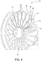
FIG. 4 is a perspective view of a fan section of the gas turbine engine ofFIG. 1 ; -
FIG. 5 is a schematic representation of a VAFN control system; -
FIG. 6 is a control theory diagram of the VAFN control system; -
FIG. 7 is a schematic representation of the VAFN control system; -
FIG. 8 is a schematic representation of the VAFN control system; -
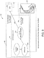
FIG. 9 is a schematic representation of the VAFN control system; -
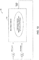
FIG. 10 is a schematic representation of a model based controller; and -
FIG. 11 is a flowchart illustrating an example process of controlling a nozzle area of a VAFN. - While the present disclosure is susceptible to various modifications and alternative constructions, certain illustrative embodiments thereof will be shown and described below in detail. The disclosure is not limited to the specific embodiments disclosed, but instead includes all modifications, alternative constructions, and equivalents thereof.
- Referring now to the drawings, and with specific reference to
FIG. 1 , anengine 20 is shown, in accordance with certain embodiments of the present disclosure. Although theengine 20 is illustrated as a gas turbine engine, the engine may be of any other type. It is to be understood that theengine 20 is shown primarily for illustrative purposes to assist in disclosing features of various embodiments, and thatFIG. 1 does not depict all of the components of an engine. Furthermore, theengine 20 is included in an aircraft and used for generating thrust. However, theengine 20 may also be included in land, marine, or aircraft applications for generating power as well. - The
engine 20 includes acore flow nozzle 22 and variable area fan nozzle (VAFN) 24. Thecore flow nozzle 22 forms a downstream end of a core engine nacelle that surrounds the core engine (not shown). The VAFN 24 is mounted to adownstream end 26 or lip area of athrust reverser sleeve 28. Thedownstream end 26 defines a downstream end of theengine 20. Thesleeve 28 overlaps at least a portion of the core engine nacelle. Theengine 20 provides thrust from both a core flow of engine exhaust exiting thecore flow nozzle 22 and a fan flow exiting from the VAFN 24. The core flow typically has a higher velocity than the fan flow. - The VAFN 24 includes a plurality of
petals 30 configured to alter the fan flow passing through a fan duct 32 of theengine 20. Thepetals 30 may be elastically deformable petals or pivotable rigid petals. In one example, each of the plurality ofpetals 30 is generally trapezoidal in shape, although thepetals 30 may have any other shape. Each of thepetals 30 include afirst side 34 and an oppositesecond side 36 that extend in a generally longitudinal direction from a supportedend 38 to afree end 40. Thepetals 30 may be disposed side by side along a circumference of the fan duct 32, with the supported ends 38 of thepetals 30 mounted to thedownstream end 26 of thethrust reverser sleeve 28. The free ends 40 of thepetals 30 form anozzle opening 42 or circumference, which is associated with a nozzle area of theVAFN 24. - The
petals 30 are configured to alter the nozzle area in order to change the fan flow passing through the fan duct 32. For instance, thepetals 30 may be moved inward or outward usingactuators flex rod 48. Theflex rod 48 may press on thepetals 30 disposed betweenactuators actuators actuators petals 30 may be used. - In the example shown in
FIG. 1 , theVAFN 24 includes two sets ofpetals 30 arranged on opposite sides of anengine pylon 50, although only one set ofpetals 30 is visible in this view. Disposed generally circumferentially, theflex rod 48 comprises a cable that extends between theactuators flex rod 48 contacts all the petals in the respective set, and ends of theflex rod 48 are attached to theactuators - In addition,
adjacent petals 30 in each set may be separated by a gap occupied by anelastomeric seal 52. Composed of silicone rubber or any other suitable material, seals 52 are used to prevent leakage of air from inside to outside theVAFN 24.Seals 52 return from a stretched condition to a nominal condition during inward actuation of thepetals 30. Other configurations for theVAFN 24 can be used. Furthermore, aspects of this disclosure may apply to other types ofVAFN 24. - Referring now to
FIG. 2 , with continued reference toFIG. 1 , theengine 20 further includes acontrol system 60 for theVAFN 24. Thecontrol system 60 comprises aprimary system 62, asecondary system 64, and acontrol module 66 in operative communication with theprimary system 62 and thesecondary system 64. Each of theprimary system 62 and thesecondary system 64 comprises a sensing system. - More specifically, the
primary system 62 is configured to acquire primary data indicative of a current operating condition of theVAFN 24 in real-time, while thesecondary system 64 is configured to acquire secondary data indicative of a current operating condition of theengine 20 in real-time. The primary data from theprimary system 62 is used to determine a current nozzle area of theVAFN 24. The secondary data from thesecondary system 64 is used to optimize or adjust the nozzle area of theVAFN 24. In so doing, an optimal position of thepetals 30 may be found based on current performance of theengine 20 and theVAFN 24. - For example, the
primary system 62 includes one or more fiber optic shape sensors, photogrammetry components, circumferential sensors, linear variable differential transformers (LVDT), and the like. Such sensing technologies provide primary data for theVAFN 24, such as strain measurements on thepetals 30, three dimensional coordinates of thepetals 30, positions of theactuators VAFN 24 in real-time. - The
secondary system 64 includes one ormore pressure sensors 68, shown inFIG. 3 , and/or one or more fanblade strain sensors 70, shown inFIG. 4 . Such sensing technologies provide secondary data for theengine 20, such as data indicative of a backpressure of theengine 20 and data indicative of a fan blade strain of theengine 20. However, other sensing technologies may be used, in addition to or instead of thepressure sensors 68 and the fanblade strain sensors 70, to acquire secondary data indicative of current operating conditions of theengine 20. The secondary data from thesecondary system 64 is used to both detect operational transients of theengine 20 and optimize the nozzle area of theVAFN 24. - More specifically, the
pressure sensors 68 are configured to determine the backpressure of theengine 20, or a pressure at an aft end of the core engine nacelle, in real-time. For example, thepressure sensors 68 may comprise LIDAR based pressure sensors, pitot tubes, and the like. Thepressure sensors 68 are disposed proximate the aft end of the core engine nacelle. - In the example shown in
FIG. 3 , thepressure sensors 68 are disposed on anattachment bulkhead 72 of theVAFN 24 that mounts to the core engine nacelle. Furthermore, in the example ofFIG. 3 , everyother petal 30 of theVAFN 24 is associated with apressure sensor 68. However, other configurations for placement and positioning of thepressure sensors 68 may be used. - The fan
blade strain sensors 70 are configured to determine the fan blade strain of theengine 20, or a strain on a plurality of blades 74 (FIG. 4 ) in a fan 76 (FIG. 4 ) of theengine 20, in real-time. The fanblade strain sensors 70 may comprise fiber optic strain sensors, or other types of strain sensors, disposed on one ormore fan blades 74 of theengine 20. For example, the fanblade strain sensors 70 may be mounted to each of thefan blades 74, alternate fan blades, or any other configuration. - In the example of
FIG. 4 , the fanblade strain sensors 70 are embedded inside thefan blades 74. For instance, within thefan blade 74, there may be a channel for receiving the fanblade strain sensor 70. However, other configurations for mounting the fanblade strain sensors 70 to thefan blades 74 may be used. - Furthermore, in the example of
FIG. 4 , each of the fanblade strain sensors 70 extends along a span of thefan blade 74 from abase 78 of theblade 74 to atip 80 of theblade 74. The fanblade strain sensors 70 may be positioned proximate aleading edge 82, a trailingedge 84, or amidpoint 86 of thefan blade 74. However, other positions for the fanblade strain sensors 70 may be used. - Referring back to
FIG. 2 , thecontrol module 66 is in operative communication with theengine 20, theVAFN 24, theprimary system 62, and thesecondary system 64. Thecontrol module 66 may be implemented using one or more of a processor, a microprocessor, a microcontrol, a digital signal processor (DSP), a field-programmable gate array (FPGA), an electronic control module (ECM), an electronic control unit (ECU), and a processor-based device that may include or be associated with a non-transitory computer readable storage medium having stored thereon computer-executable instructions, or any other suitable means for electronically controlling functionality of theengine 20, theVAFN 24, and the plurality ofpetals 30. - In the example of
FIG. 2 , thecontrol module 66 comprises aVAFN control unit 90 and an engineelectronic control 92. However, other configurations for thecontrol module 66 may be used. Each of theVAFN control unit 90 and the engineelectronic control 92 is configured to operate according to predetermined algorithms or sets of instructions for operating thecontrol system 60. - Such algorithms or sets of instructions may be programmed or incorporated into a
memory 94 and amemory 96 associated with or at least accessible to theVAFN control unit 90 and the engineelectronic control 92, respectively. Each of thememories VAFN control unit 90 and the engineelectronic control 92, respectively. It is understood that theVAFN control unit 90, the engineelectronic control 92, and thecontrol system 60 may include other hardware, software, firmware, and combinations thereof. - Furthermore, the engine
electronic control 92 is configured to generate a desired nozzle area and send a corresponding signal to theVAFN control unit 90. In one example, the engineelectronic control 92 may generate the desired nozzle area based on an engine operating condition. For instance, the engineelectronic control 92 may include a predetermined table of optimum or desired nozzle areas for different engine operating conditions in order to achieve a desired result. The predetermined table of desired nozzle areas may be preprogrammed into thememory 96 associated with the engineelectronic control 92. - Examples of engine operating conditions may include take-off, climb, cruise, flight conditions, thrust conditions, and the like. Examples of desired results may include a lower fuel burn, a fuel flow, a thrust, and the like. Based on the real-time engine operating condition, the engine
electronic control 92 retrieves frommemory 96 the desired nozzle area from the predetermined table. - The engine
electronic control 92 then sends a command to theVAFN control unit 90 to achieve an appropriate opening area of theVAFN 24 for the current engine operating condition. The engineelectronic control 92 can also determine that no optimum area can be achieved for a particular engine operating condition and may determine a non-optimum area for that particular condition. TheVAFN control unit 90 controls the rate of movement of thepetals 30 to different positions or maintains a position to achieve the desired nozzle area. - Based, at least in part, on the signal indicative of the desired nozzle area from the engine
electronic control 92, theVAFN control unit 90 sends corresponding signals to the electrohydraulic servo valve in order to control hydraulic flow to theactuators VAFN control unit 90 may send signals to the electrohydraulic servo valve to increase or decrease hydraulic flow to theactuators flex rod 48 and move thepetals 30 outward or inward in order to change the shape of the nozzle opening 42 (FIG. 1 ) and achieve the desired nozzle area. TheVAFN control unit 90 may also send signals to the electrohydraulic servo valve to maintain a same hydraulic flow to theactuators - Referring now to
FIG. 5 , with continued reference toFIGS. 1-4 , another schematic representation of thecontrol system 60 is shown. In this aspect, thecontrol module 66 is further configured to optimize the nozzle area of theVAFN 24 based on the primary data and the secondary data from theprimary system 62 and thesecondary system 64, respectively. More specifically, theVAFN control unit 90 is configured to receive from theprimary system 62 the primary data, such as data indicative of the strain measurements on thepetals 30, the three dimensional coordinates of thepetals 30, and the positions of the actuators. Based on the primary data, theVAFN control unit 90 is configured to determine a real-time nozzle area of theVAFN 24, atmodule 100. - For example, along with the primary data from the
primary system 62, theVAFN control unit 90 may use predetermined formulae and information, such as an installation geometry of theVAFN 24, preprogrammed intomemory 94 in order to calculate the real-time nozzle area of theVAFN 24. TheVAFN control unit 90 is also configured to receive the signal from the engineelectronic control 92 indicative of the desired nozzle area. Furthermore, theVAFN control unit 90 is configured to determine a difference between the real-time nozzle area and the desired nozzle area, atmodule 102. Based, at least in part, on the determined difference between the calculated nozzle area and the desired nozzle area, theVAFN control unit 90 is further configured to use control laws to generate an actuator command to adjust thepetals 30 of theVAFN 24, atmodule 104. - The actuator command is sent to the electrohydraulic servo valves that control hydraulic flow to the
actuators flex rod 48 in contact with thepetals 30. For example, theVAFN control unit 90 may be configured to use proportional integral differential (PID), linear quadratic regression (LQR), or bang-bang control. However, other types of feedback loop control and control laws may be used. More specifically, using control laws such as PID, LQR, or bang-bang control, theVAFN control unit 90 continuously applies the difference between the calculated nozzle area in real-time and the desired nozzle area as feedback in order to generate actuator commands and modify the real-time nozzle area. - In addition, the
control module 66 is further configured to adjust the real-time nozzle area based on the secondary data from thesecondary system 64. More specifically, the engineelectronic control 92 is configured to receive the secondary data from thesecondary system 64, such as data indicative of a real-time backpressure of theengine 20 and/or a real-time fan blade strain of theengine 20. Based on the secondary data, the engineelectronic control 92 is configured to determine a difference between the secondary data and predetermined values for the same, atmodule 106. - The predetermined values for the backpressure and the fan blade strain are preprogrammed into the
memory 96 associated with the engineelectronic control 92. For example, atmodule 108, the predetermined values for the backpressure and the fan blade strain comprise expected values for the backpressure and the fan blade strain, respectively, based on a flight condition, an engine speed, a Mach number, an altitude, and the like. The predetermined values for the backpressure and the fan blade strain are determined from prior analysis, such as computer simulation, model-based analysis, ground test results, in-flight test results, and the like. - A difference between the real-time backpressure and the predetermined backpressure is determined by the engine
electronic control 92, as well as a difference between the real-time fan blade strain and the predetermined fan blade strain. The engineelectronic control 92 is further configured to use control laws to generate an actuator command to send to theVAFN control unit 90, atmodule 110. For example, the engineelectronic control 92 may be configured to use proportional integral differential (PID), linear quadratic regression (LQR), or bang-bang control, although other types of feedback loop control and control laws may be used. The engineelectronic control 92 uses the control laws to continuously apply the difference between the secondary data and the predetermined values in order to generate actuator commands and modify the real-time nozzle area. - Furthermore, the
control module 66 includes anadder 112 configured to combine the actuator command from the engineelectronic control 92 with the control laws, atmodule 104, in theVAFN control unit 90 in order to generate the actuator command to theVAFN 24 to adjust thepetals 30. Theadder 112 incorporates the secondary data with the primary data to optimize the nozzle area of theVAFN 24. In so doing, thecontrol module 66 uses both sensor feedback from theengine 20 and sensor feedback from theVAFN 24 in order to accurately position thepetals 30, thereby achieving enhanced performance for fuel burn, operability, and/or thrust at different flight conditions. - Turning now to
FIG. 6 , with continued reference toFIGS. 1-5 , a control theory diagram of thecontrol system 60 is shown. In this aspect, the secondary data is used in a performance seeking control that performs a sweep of the nozzle area in slight increments and selects an optimum or desired position for thepetals 30 of theVAFN 24 from the sweep for the flight condition, atmodule 120. More specifically, thecontrol module 66 is configured to move theactuators VAFN 24 within a predetermined tolerance and select an actuator position that provides an optimum or desired backpressure result and/or an optimum or desired fan blade strain result. For example, the predetermined tolerance can be set to one percent (1%) of a nominal nozzle area based on a cruise flight condition. However, other values for the predetermined tolerance may be used. - The
control module 66 sends signals to increase or decrease hydraulic flow to theactuators flex rod 48 and move thepetals 30 outward or inward about a current position of thepetals 30. With each slight increment theactuators VAFN 24 is changed, and the real-time backpressure and the real-time fan blade strain from thesecondary system 64 are monitored. The optimum or desired position for thepetals 30 is selected based on the actuator position that provides the optimum or desired backpressure result and/or the optimum or desired fan blade strain result. For example, to obtain the optimum or desired results, thecontrol module 66 may be configured to determine a minimum or a maximum of a cost function based on the real-time backpressure and the real-time fan blade strain. - In addition, the
control module 66 is configured to use the optimum or desired results from the sweep of the performance seeking control in order to adjust the desired nozzle area from the engineelectronic control 92. For instance, thecontrol module 66 may include afirst adder 122 to bias the desired nozzle area based on the optimum or desired results from the sweep of the performance seeking control. Furthermore, thecontrol module 66 may include asecond adder 124 that combines the biased desired nozzle area from thefirst adder 122 with the primary data from theprimary system 62 in order to obtain an adjusted nozzle area. Atmodule 104, control laws, such as PID, LQR, or bang-bang control, are used by thecontrol module 66 to generate and send actuator commands to theVAFN 24 in order to achieve the adjusted nozzle area. -
FIG. 7 shows an implementation of the control theory diagram ofFIG. 6 . In this aspect, thecontrol module 66 implements performance seeking control via theVAFN control unit 90. More specifically, atmodule 130, theVAFN control unit 90 is configured to perform the sweep to obtain the actuator position that provides the optimum or desired backpressure result and/or the optimum or desired fan blade strain result. TheVAFN control unit 90 is further configured to use control laws, such as PID, LQR, or bang-bang control, on the actuator position obtained by the sweep to generate a nozzle area bias, atmodule 132. Furthermore,module 132 selects the nozzle area bias that provides the optimum or desired result from a cost function based on, for example, a maximum thrust, a minimum fuel flow, a minimum backpressure, a minimum fan blade strain, a weighted combination thereof, and the like. - At
module 134, the nozzle area bias is used to adjust the desired nozzle area from the engineelectronic control 92 to produce an adjusted desired nozzle area for theVAFN 24. Atmodule 102, a difference between the adjusted desired nozzle area and the calculated nozzle area based on the primary data, frommodule 100, is determined by theVAFN control unit 90. Atmodule 104, control laws, such as PID, LQR, or bang-bang control, are applied to the difference between the adjusted desired nozzle area and the calculated nozzle area in order to generate and send actuator commands to theVAFN 24 to position thepetals 30. For instance,module 104 drives the difference between the adjusted desired nozzle area and the calculated nozzle area to zero by changing the actuator commands sent to theVAFN 24. However, other configurations for thecontrol module 66 may be used. - Referring now to
FIG. 8 , with continued reference toFIGS. 1-7 , another schematic representation of thecontrol system 60 is shown. In the example ofFIG. 8 , the engineelectronic control 92 is configured to determine operational transients of theengine 20. More specifically, engineelectronic control 92 receives the secondary data, such as current values for the backpressure and/or the fan blade strain, and compares the secondary data to predetermined values for the same. - At
module 140, a difference between the real-time value and the predetermined value for each of the backpressure and the fan blade strain is calculated by the engineelectronic control 92. The engineelectronic control 92 determines if the difference between the current value and the expected value is within a predetermined range preprogrammed into thememory 96 associated with the engineelectronic control 92, atmodule 142. The predetermined range for the difference includes an upper limit and a lower limit of acceptable values for the difference between the current value and the expected value for each of the backpressure and the fan blade strain. The upper and lower limits are selected based on a type of theengine 20 and/or theVAFN 24. - If the difference between the current value and the expected value for the backpressure and/or the fan blade strain is outside of the predetermined range, the engine
electronic control 92 determines an operational transient of theengine 20 is occurring and sends a signal to alert aircraft crew members. For example, the engineelectronic control 92 may send a signal to an Engine Indication and Crew Alert System (EICAS) to generate a message alerting aircraft crew members. In addition, the engineelectronic control 92 may send a signal to theVAFN control unit 90 to move the plurality ofpetals 30 to a failsafe position when the secondary data indicates the operational transient. - Based on the signal from the engine
electronic control 92, theVAFN control unit 90 may send corresponding signals to the electrohydraulic servo valve in order to control hydraulic flow to theactuators VAFN control unit 90 may send signals to the electrohydraulic servo valve to increase or decrease hydraulic flow to theactuators flex rod 48 and move thepetals 30 outward or inward in order to achieve the failsafe position. In one example, the failsafe position comprises moving thepetals 30 maximally outward such that thenozzle opening 42 attains a maximum nozzle area. - In another example, the failsafe position comprises a floating condition wherein the
petals 30 are floating, or moving with aerodynamic and thrust forces impinging on thepetals 30. In yet another example, the failsafe position comprises moving thepetals 30 maximally outward then to the floating condition if the maximum nozzle area cannot be achieved. However, other configurations for the failsafe position may be used. - Referring now to
FIG. 9 , with continued reference toFIGS. 1-8 , another schematic representation of thecontrol system 60 is shown. In this example, theVAFN control unit 90 is configured to determine operational transients of theengine 20. The determination of operational transients of theengine 20 is similar to the example ofFIG. 8 , except with the determination being performed by theVAFN control unit 90 instead of the engineelectronic control 92. More specifically, theVAFN control unit 90 receives the secondary data, such as current values for the backpressure and/or the fan blade strain, and compares the secondary data to the predetermined values for the same, which are preprogrammed into thememory 94 of the VAFN control unit. - At
module 150, theVAFN control unit 90 calculates the difference between the secondary data and the predetermined values, and determines whether the difference is within the predetermined range preprogrammed into thememory 94 of theVAFN control unit 90, atmodule 152. If the difference between the current value and the expected value for the backpressure and/or the fan blade strain is outside of the predetermined range, theVAFN control unit 90 determines an operational transient of theengine 20. TheVAFN control unit 90 then sends a signal to the engineelectronic control 92 to alert aircraft crew members and/or sends signals to theVAFN 24 to move the plurality ofpetals 30 to the failsafe position when the secondary data indicates the operational transient. - Turning now to
FIG. 10 , with continued reference toFIGS. 1-9 , thecontrol module 66 may further include a model basedcontroller 160. The model basedcontroller 160 may be implemented via theVAFN control unit 90 or a separate processor-based device. Furthermore, the model basedcontroller 160 includes a learning algorithm preprogrammed into thememory 94 associated with theVAFN control unit 90 or other processor-based device. With the learning algorithm, the model basedcontroller 160 learns or estimates the real-time nozzle area of theVAFN 24. - More specifically, the model based
controller 160 comprises a mathematical model that receives inputs from the engineelectronic control 92 and theVAFN control unit 90 and continuously adapts constants in the mathematical model based on the received inputs. Inputs from the engineelectronic control 92 may include, but not be limited to, engine speeds, engine temperatures, Mach numbers, desired nozzle areas, and the like. Inputs from theVAFN control unit 90 may include, but not be limited to, sensor feedback from theVAFN 24, calculated nozzle areas determined by theVAFN control unit 90, and the like. - The mathematical model matches the nozzle area of the
VAFN 24 as a function of the inputs from the engineelectronic control 92 and theVAFN control unit 90. The model basedcontroller 160, therefore, represents a real-time performance and life span of theengine 20. In so doing, the model basedcontroller 160 can function as a backup controller to estimate the real-time nozzle area of theVAFN 24 if the primary data from theprimary system 62 is unavailable. For example, when an operational transient of theengine 20 is determined, the model basedcontroller 160 stops adapting constants in the mathematical model and uses the inputs from the engineelectronic control 92 and a final updated version of the mathematical model to estimate the real-time nozzle area of theVAFN 24. This allows for a time-limited dispatch of theengine 20 without reliance on theprimary system 62. - In addition, the model based
controller 160 can provide an alternate means for detection of operational transients of theengine 20. The model basedcontroller 160 is configured to compare the estimated nozzle area from the mathematical model to the calculated nozzle area determined by theVAFN control unit 90. If the estimated nozzle area from the mathematical model is unequal to the calculated nozzle area from theVAFN control unit 90, or if the estimated nozzle area is outside a predetermined margin of the calculated nozzle area from theVAFN control unit 90, then the model basedcontroller 160 is configured to determine an operational transient of theengine 20. The model basedcontroller 160 is further configured to send signals to the engineelectronic control 92 in order to alert aircraft crew members of the operational transient. - From the foregoing, it can be seen that the teachings of this disclosure can find industrial application, technical effects and benefits in any number of different situations, including but not limited to, engines, such as gas turbine engines. Such engines may be used, for example, on aircraft for generating thrust, or in land, marine, or aircraft applications for generating power.
- The present disclosure provides a control system for a variable area fan nozzle (VAFN) of a gas turbine engine. The disclosed control system uses primary system sensor data from the VAFN in order to determine a real-time nozzle area, along with predetermined lookup tables preprogrammed into a memory associated with the control system to generate an actuator command for the petals of the VAFN. In addition, the disclosed control system uses secondary system sensor data from the engine to adjust the generated actuator command and the nozzle area of the VAFN for performance seeking control.
- The secondary system sensor data includes a backpressure of the engine and/or a fan blade strain of the engine. With the secondary system sensor data, the disclosed control system also detects operational transients of the engine, alerts aircraft crew members of the operational transients, and moves the petals of the VAFN to a failsafe position when operational transients are detected. The disclosed control system further includes a model based controller that learns and estimates the real-time nozzle area based on inputs from the engine electronic control. In so doing, the disclosed control system provides a redundant or secondary system for fine control of the VAFN and performance monitoring of the engine.
- Referring now to
FIG. 11 , with continued reference toFIGS. 1-10 , a flowchart illustrating anexample process 170 of controlling a nozzle area of aVAFN 24 is shown. TheVAFN 24 has a plurality ofpetals 30 and is for use with agas turbine engine 20. Atblock 172, primary data indicative of an operating condition of theVAFN 24 is acquired from theprimary system 62. Atblock 174, secondary data indicative of a backpressure and a fan blade strain of thegas turbine engine 20 is acquired from thesecondary system 64. - The nozzle area of the
VAFN 24 is calculated by theVAFN control unit 90 based on the primary data, atblock 176. A desired nozzle area based at least in part on a predetermined table of nozzle areas is generated by the engineelectronic control 92, atblock 178. Atblock 180, an actuator command is produced by theVAFN control unit 90 based on a difference between the calculated nozzle area and the desired nozzle area. - The actuator command is adjusted by the
VAFN control unit 90 based on the secondary data, atblock 182. However, instead of the actuator command, the desired nozzle area may be adjusted based on the secondary data, as described above in the example ofFIGS. 6 and7 . Atblock 184, the adjusted actuator command is sent to theVAFN 24 to move the plurality ofpetals 30. Acontrol module 66, including theVAFN control unit 90 and the engineelectronic control 92, associated with theVAFN 24 and thegas turbine engine 20 performs the calculating, generating, producing, adjusting, and sending. - It is to be understood that the flowchart in
FIG. 11 is shown and described as an example only to assist in disclosing the features of the disclosed control system, and that more or less steps than that shown may be included in the processes corresponding to the various features described above for the disclosed control system without departing from the scope of the disclosure. - Further, the disclosure comprises embodiments according to the following clauses:
- Clause 1. A control system for a variable area fan nozzle (VAFN) having a plurality of petals, the VAFN for use with a gas turbine engine, the control system comprising: a primary system configured to acquire primary data indicative of an operating condition of the VAFN; a secondary system configured to acquire secondary data indicative of a current operating condition of the gas turbine engine; and a control module in operative communication with the primary system and the secondary system, the control module configured to: determine a nozzle area of the VAFN based at least in part on the primary data, adjust the determined nozzle area based on the secondary data, and position the plurality of petals according to the adjusted nozzle area.
- Clause 2. The control system of Clause 1, wherein the secondary data includes data indicative of a backpressure of the gas turbine engine.
- Clause 3. The control system of Clause 2, wherein the secondary system includes at least one pressure sensor configured to determine the backpressure of the gas turbine engine.
- Clause 4. The control system of Clause 3, wherein the at least one pressure sensor is disposed proximate an aft end of a core engine nacelle of the gas turbine engine.
- Clause 5. The control system of any one of Clauses 1 to 4, wherein the secondary data includes data indicative of a fan blade strain of the gas turbine engine.
- Clause 6. The control system of Clause 5, wherein the secondary system includes at least one strain sensor configured to determine the fan blade strain of the gas turbine engine.
- Clause 7. The control system of Clause 6, wherein the at least one strain sensor comprises a fiber optic strain sensor disposed on a fan blade of the gas turbine engine.
- Clause 8. The control system of any one of Clauses 1 to 7, wherein the control module is further configured to determine an operational transient of the gas turbine engine based on the secondary data.
- Clause 9. The control system of Clause 8, wherein the control module is further configured to send a signal to alert aircraft crew members of the operational transient.
- Clause 10. The control system of Clause 8 or 9, wherein the control module is further configured to move the plurality of petals to a failsafe position when the secondary data indicates the operational transient.
- Clause 11. An aircraft comprising: a gas turbine engine; a variable area fan nozzle (VAFN) mounted to a downstream end of the gas turbine engine, the VAFN including a plurality of petals; and the control system of Clauses 1 to 10 in operative communication with the gas turbine engine and the VAFN
- Clause 12. An aircraft comprising: a gas turbine engine; a variable area fan nozzle (VAFN) mounted to a downstream end of the gas turbine engine, the VAFN including a plurality of petals and at least one actuator configured to move the plurality of petals; and a control system in operative communication with the gas turbine engine and the VAFN, the control system including: at least one pressure sensor configured to determine a backpressure of the gas turbine engine; at least one strain sensor configured to determine a fan blade strain of the gas turbine engine; and a control module in operative communication with the at least one pressure sensor, the at least one strain sensor, and a primary system configured to configured to acquire primary data indicative of an operating condition of the VAFN, the control module configured to: calculate a real-time nozzle area of the VAFN based at least in part on the primary data, generate an actuator command based at least in part on the real-time nozzle area and a predetermined table of nozzle areas preprogrammed into a memory of the control module, modify the actuator command based on at least one of the determined backpressure and the determined fan blade strain, and send the modified actuator command to the at least one actuator of the VAFN to adjust the plurality of petals.
- Clause 13. The aircraft of Clause 12, wherein the at least one pressure sensor comprises one of a LIDAR based pressure sensor or a pitot tube.
- Clause 14. The aircraft of Clause 12 or 13, wherein the control module is implemented via an engine electronic control and a VAFN control unit.
- Clause 15. The aircraft of Clause 14, wherein the control module includes a model based controller configured to estimate a nozzle area of the VAFN when primary data is unavailable.
- Clause 16. The aircraft of Clause 15, wherein the model based controller includes a learning algorithm for estimating the nozzle area based on inputs into the engine electronic control.
- Clause 17. The aircraft of Clause 16, wherein the control module is further configured to determine an operational transient of the gas turbine engine if the estimated nozzle area from the model based controller is outside a predetermined margin of a calculated nozzle area determined by the VAFN control unit.
- Clause 18. A method for controlling a nozzle area of a variable area fan nozzle (VAFN) having a plurality of petals, the VAFN for use with a gas turbine engine, the method comprising: acquiring primary data indicative of an operating condition of the VAFN; acquiring secondary data indicative of a backpressure and a fan blade strain of the gas turbine engine; calculating the nozzle area of the VAFN based on the primary data; generating a desired nozzle area based at least in part on a predetermined table of nozzle areas; producing an actuator command based on a difference between the calculated nozzle area and the desired nozzle area; adjusting the actuator command based on the secondary data; and sending the adjusted actuator command to the VAFN to move the plurality of petals, the calculating, generating, producing, adjusting, and sending being performed by a control module associated with the VAFN and the gas turbine engine.
- Clause 19. The method of Clause 18, further comprising learning a nozzle area of the VAFN based on inputs into an engine electronic control of the gas turbine engine, the learning being performed by a model based controller of the control module.
-
Clause 20. The method of Clause 18 or 19, further comprising using the secondary data to determine an operational transient of the gas turbine engine. - Clause 21. The method of
Clause 20, further comprising alerting aircraft crew members of the operational transient and moving the plurality of petals of the VAFN to a failsafe position when the operational transient is determined. - While the foregoing detailed description has been given and provided with respect to certain specific embodiments, it is to be understood that the scope of the disclosure should not be limited to such embodiments, but that the same are provided simply for enablement and best mode purposes. The breadth and spirit of the present disclosure is broader than the embodiments specifically disclosed and encompassed within the claims appended hereto. Moreover, while some features are described in conjunction with certain specific embodiments, these features are not limited to use with only the embodiment with which they are described, but instead may be used together with or separate from, other features disclosed in conjunction with alternate embodiments.
Claims (15)
- A control system (60) for a variable area fan nozzle variable area fan nozzle (24) having a plurality of petals (30), the variable area fan nozzle for use with a gas turbine engine (20), the control system comprising:a primary system (62) configured to acquire primary data indicative of an operating condition of the variable area fan nozzle;a secondary system (64) configured to acquire secondary data indicative of a current operating condition of the gas turbine engine; anda control module (66) in operative communication with the primary system and the secondary system, the control module configured to:determine a nozzle area of the variable area fan nozzle based at least in part on the primary data,adjust the determined nozzle area based on the secondary data, andposition the plurality of petals according to the adjusted nozzle area.
- The control system (60) of claim 1, wherein the secondary data includes data indicative of a backpressure of the gas turbine engine (20), preferably wherein the secondary system (64) includes at least one pressure sensor (68) configured to determine the backpressure of the gas turbine engine.
- The control system (60) of claim 2, wherein the at least one pressure sensor (68) is disposed proximate an aft end of a core engine nacelle of the gas turbine engine (20).
- The control system (60) of any one of claims 1 to 3, wherein the secondary data includes data indicative of a fan blade strain of the gas turbine engine (20), preferably wherein the secondary system (64) includes at least one fan blade strain sensor (70) configured to determine the fan blade strain of the gas turbine engine.
- The control system (60) of claim 4, wherein the at least one fan blade strain sensor (70) comprises a fiber optic strain sensor disposed on a fan blade (74) of the gas turbine engine (20).
- The control system (60) of any one of claims 1 to 5, wherein the control module (66) is further configured to determine an operational transient of the gas turbine engine (20) based on the secondary data, preferably wherein the control module is further configured to move the plurality of petals (30) to a failsafe position when the secondary data indicates the operational transient.
- The control system (60) of claim 6, wherein the control module (66) is further configured to send a signal to alert aircraft crew members of the operational transient.
- An aircraft comprising:a gas turbine engine (20);a variable area fan nozzle (24) mounted to a downstream end (26) of the gas turbine engine, the variable area fan nozzle including a plurality of petals (30) and at least one actuator (44, 46) configured to move the plurality of petals; andthe control system (60) of any one of Claims 1 to 7 in operative communication with the gas turbine engine and the variable area fan nozzle, wherein:the secondary system (64) includes at least one pressure sensor (68) configured to determine a backpressure of the gas turbine engine and at least one fan blade strain sensor (70) configured to determine a fan blade strain of the gas turbine engine; andthe control module (66) is configured to:calculate a real-time nozzle area of the variable area fan nozzle based at least in part on the primary data,generate an actuator command based at least in part on the real-time nozzle area and a predetermined table of nozzle areas preprogrammed into a memory of the control module,modify the actuator command based on at least one of the determined backpressure and the determined fan blade strain, andsend the modified actuator command to the at least one actuator of the variable area fan nozzle to position the plurality of petals.
- The aircraft of claim 8, wherein the at least one pressure sensor (68) comprises one of a LIDAR based pressure sensor or a pitot tube.
- The aircraft of claim 8 or 9, wherein the control module (66) is implemented via an engine electronic control (92) and a variable area fan nozzle control unit (92).
- The aircraft of claim 10, wherein the control module (66) includes a model based controller (160) configured to estimate a nozzle area of the variable area fan nozzle (24) when primary data is unavailable,
preferably wherein the model based controller includes a learning algorithm for estimating the nozzle area based on inputs into the engine electronic control (92), and
preferably wherein the control module is further configured to determine an operational transient of the gas turbine engine if the estimated nozzle area from the model based controller is outside a predetermined margin of a calculated nozzle area determined by the variable area fan nozzle control unit (92). - A method (170) for controlling a nozzle area of a variable area fan nozzle (24) having a plurality of petals (30), the variable area fan nozzle for use with a gas turbine engine (20), the method comprising:acquiring (172) primary data indicative of an operating condition of the variable area fan nozzle;acquiring (174) secondary data indicative of a backpressure and a fan blade strain of the gas turbine engine;calculating (176) the nozzle area of the variable area fan nozzle based on the primary data;generating (178) a desired nozzle area based at least in part on a predetermined table of nozzle areas;producing (180) an actuator command based on a difference between the calculated nozzle area and the desired nozzle area;adjusting (182) the actuator command based on the secondary data; andsending (184) the adjusted actuator command to the variable area fan nozzle to move the plurality of petals, the calculating, generating, producing, adjusting, and sending being performed by a control module (66) associated with the variable area fan nozzle and the gas turbine engine.
- The method (170) of claim 12, further comprising learning a nozzle area of the variable area fan nozzle (24) based on inputs into an engine electronic control (92) of the gas turbine engine (20), the learning being performed by a model based controller (160) of the control module (66).
- The method (170) of claim 12 or 13, further comprising using the secondary data to determine an operational transient of the gas turbine engine (20).
- The method (170) of claim 14, further comprising alerting aircraft crew members of the operational transient and moving the plurality of petals (30) of the variable area fan nozzle (24) to a failsafe position when the operational transient is determined.
Applications Claiming Priority (1)
| Application Number | Priority Date | Filing Date | Title |
|---|---|---|---|
| US15/169,155 US9803586B1 (en) | 2016-05-31 | 2016-05-31 | Secondary systems and methods of control for variable area fan nozzles |
Publications (2)
| Publication Number | Publication Date |
|---|---|
| EP3252293A1 true EP3252293A1 (en) | 2017-12-06 |
| EP3252293B1 EP3252293B1 (en) | 2019-02-20 |
Family
ID=58185275
Family Applications (1)
| Application Number | Title | Priority Date | Filing Date |
|---|---|---|---|
| EP17157241.5A Active EP3252293B1 (en) | 2016-05-31 | 2017-02-21 | Secondary systems and methods of control for variable area fan nozzles |
Country Status (6)
| Country | Link |
|---|---|
| US (1) | US9803586B1 (en) |
| EP (1) | EP3252293B1 (en) |
| JP (1) | JP6893795B2 (en) |
| KR (1) | KR102266769B1 (en) |
| CN (1) | CN107448422B (en) |
| RU (1) | RU2726018C2 (en) |
Cited By (1)
| Publication number | Priority date | Publication date | Assignee | Title |
|---|---|---|---|---|
| FR3120604A1 (en) * | 2021-03-15 | 2022-09-16 | Safran | ASSEMBLY COMPRISING A MECHANICAL PART OF AN AIRCRAFT TURBOMACHINE AND AN AIRCRAFT TURBOMACHINE MONITORING DEVICE |
Families Citing this family (7)
| Publication number | Priority date | Publication date | Assignee | Title |
|---|---|---|---|---|
| US10422301B2 (en) * | 2015-07-13 | 2019-09-24 | The Boeing Company | Telescoping electrical cable |
| US11125157B2 (en) | 2017-09-22 | 2021-09-21 | The Boeing Company | Advanced inlet design |
| FR3094790B1 (en) * | 2019-04-05 | 2021-03-05 | Safran Aircraft Engines | System for monitoring a system for actuating a component of a turbomachine |
| BR102022003769A2 (en) | 2021-05-04 | 2022-11-16 | The Boeing Company | NACELE ENTRY STRUCTURE OF AN ENGINE ASSEMBLY |
| US11421607B1 (en) * | 2021-06-10 | 2022-08-23 | Raytheon Technologies Corporation | Fiber optic exit area sensing for gas turbine engine nozzles |
| CN114856833B (en) * | 2022-04-27 | 2023-06-23 | 中国民航大学 | A redundant control method and device for a large bypass ratio turbofan engine |
| CN116025482B (en) * | 2022-12-31 | 2025-08-19 | 中国航发沈阳发动机研究所 | Combined spray pipe cooperative control method based on master-slave and bang-bang control |
Citations (5)
| Publication number | Priority date | Publication date | Assignee | Title |
|---|---|---|---|---|
| US20060104561A1 (en) * | 2004-11-12 | 2006-05-18 | Gennadii Ivtsenkov | Fiber optic strain sensor and associated data acquisition system |
| US20120124965A1 (en) * | 2008-03-05 | 2012-05-24 | Grabowski Zbigniew M | Variable area fan nozzle fan flutter management system |
| WO2013158180A2 (en) * | 2012-01-31 | 2013-10-24 | United Technologies Corporation | Variable area fan nozzle fan flutter management system |
| US20150315976A1 (en) * | 2012-01-31 | 2015-11-05 | United Technologies Corporation | Gas turbine engine variable area fan nozzle control |
| US20160138523A1 (en) * | 2014-11-14 | 2016-05-19 | United Technologies Corporation | Optimal Thrust Control of an Aircraft Engine |
Family Cites Families (16)
| Publication number | Priority date | Publication date | Assignee | Title |
|---|---|---|---|---|
| US8157533B2 (en) * | 2005-10-17 | 2012-04-17 | Vestas Wind Systems A/S | Wind turbine blade with variable aerodynamic profile |
| US8308423B2 (en) * | 2006-10-12 | 2012-11-13 | United Technologies Corporation | Variable area fan nozzle for accommodating a foreign object strike event |
| CA2680159A1 (en) * | 2007-03-08 | 2008-09-12 | Jimmy L. Blaylock | Turbocharger with adjustable throat |
| GB0706270D0 (en) * | 2007-03-30 | 2007-05-09 | Goodrich Actuation Systems Ltd | Actuator arrangement |
| RU101736U1 (en) * | 2010-09-30 | 2011-01-27 | Федеральное государственное унитарное предприятие "Московское машиностроительное производственное предприятие "САЛЮТ" (ФГУП "ММПП "САЛЮТ") | CRITICAL AREA CONTROL SYSTEM FOR A TWO-CURRENT GAS-TURBINE ENGINE REACTIVE NOZZLE |
| US9021813B2 (en) | 2011-07-18 | 2015-05-05 | The Boeing Company | Cable-actuated variable area fan nozzle with elastomeric seals |
| US20130075494A1 (en) * | 2011-09-28 | 2013-03-28 | Honeywell International Inc. | Vafn systems with nozzle locking assemblies |
| US20130078081A1 (en) * | 2011-09-28 | 2013-03-28 | Honeywell International Inc. | Vafn systems with improved drive coupling assemblies and brakes |
| US20130145768A1 (en) * | 2011-12-08 | 2013-06-13 | Honeywell International Inc. | Case assembly with fuel or hydraulic driven vafn actuation systems |
| BR102012032396B1 (en) * | 2012-01-17 | 2021-01-05 | United Technologies Corporation | engine mast assembly, and gas turbine engine system |
| US9091230B2 (en) | 2012-05-16 | 2015-07-28 | The Boeing Company | Linked ring petal actuation for variable area fan nozzle |
| US9488130B2 (en) * | 2013-10-17 | 2016-11-08 | Honeywell International Inc. | Variable area fan nozzle systems with improved drive couplings |
| EP3068994B1 (en) * | 2013-11-15 | 2019-08-07 | United Technologies Corporation | Component with embedded sensor |
| US9869275B2 (en) * | 2014-04-24 | 2018-01-16 | Rohr, Inc. | Single actuator variable area fan nozzle system and method |
| US9856742B2 (en) * | 2015-03-13 | 2018-01-02 | Rohr, Inc. | Sealing system for variable area fan nozzle |
| US10030608B2 (en) * | 2015-05-15 | 2018-07-24 | Rohr Inc. | Variable area fan nozzle actuation system |
-
2016
- 2016-05-31 US US15/169,155 patent/US9803586B1/en active Active
-
2017
- 2017-02-15 JP JP2017025684A patent/JP6893795B2/en active Active
- 2017-02-15 RU RU2017104901A patent/RU2726018C2/en active
- 2017-02-21 EP EP17157241.5A patent/EP3252293B1/en active Active
- 2017-03-08 CN CN201710133736.XA patent/CN107448422B/en active Active
- 2017-04-20 KR KR1020170051026A patent/KR102266769B1/en active Active
Patent Citations (5)
| Publication number | Priority date | Publication date | Assignee | Title |
|---|---|---|---|---|
| US20060104561A1 (en) * | 2004-11-12 | 2006-05-18 | Gennadii Ivtsenkov | Fiber optic strain sensor and associated data acquisition system |
| US20120124965A1 (en) * | 2008-03-05 | 2012-05-24 | Grabowski Zbigniew M | Variable area fan nozzle fan flutter management system |
| WO2013158180A2 (en) * | 2012-01-31 | 2013-10-24 | United Technologies Corporation | Variable area fan nozzle fan flutter management system |
| US20150315976A1 (en) * | 2012-01-31 | 2015-11-05 | United Technologies Corporation | Gas turbine engine variable area fan nozzle control |
| US20160138523A1 (en) * | 2014-11-14 | 2016-05-19 | United Technologies Corporation | Optimal Thrust Control of an Aircraft Engine |
Cited By (1)
| Publication number | Priority date | Publication date | Assignee | Title |
|---|---|---|---|---|
| FR3120604A1 (en) * | 2021-03-15 | 2022-09-16 | Safran | ASSEMBLY COMPRISING A MECHANICAL PART OF AN AIRCRAFT TURBOMACHINE AND AN AIRCRAFT TURBOMACHINE MONITORING DEVICE |
Also Published As
| Publication number | Publication date |
|---|---|
| RU2017104901A3 (en) | 2020-04-23 |
| BR102017010208A2 (en) | 2017-12-19 |
| EP3252293B1 (en) | 2019-02-20 |
| CN107448422A (en) | 2017-12-08 |
| RU2017104901A (en) | 2018-08-15 |
| KR102266769B1 (en) | 2021-06-18 |
| RU2726018C2 (en) | 2020-07-08 |
| JP6893795B2 (en) | 2021-06-23 |
| KR20170135668A (en) | 2017-12-08 |
| CN107448422B (en) | 2020-07-31 |
| US9803586B1 (en) | 2017-10-31 |
| JP2017214918A (en) | 2017-12-07 |
Similar Documents
| Publication | Publication Date | Title |
|---|---|---|
| US9803586B1 (en) | Secondary systems and methods of control for variable area fan nozzles | |
| CA2955395C (en) | Controlling a gas turbine engine to account for airflow distortion | |
| CA2955461C (en) | Adjusting airflow distortion in gas turbine engine | |
| US10794281B2 (en) | Gas turbine engine having instrumented airflow path components | |
| CA2923376C (en) | Controlling nozzle areas of variable area fan nozzles | |
| EP4035998B1 (en) | System and method for detecting failure of a propeller feedback device | |
| JP2007247648A (en) | Continuous real-time EGT margin control method and system | |
| US10184425B2 (en) | Fiber optic sensing for variable area fan nozzles | |
| US20230150681A1 (en) | Gas turbine engine noise reduction | |
| US9630706B2 (en) | Positionable ejector member for ejector enhanced boundary layer alleviation | |
| RU2312244C1 (en) | Method of control of vectored-thrust nozzle of aircraft gas-turbine engine | |
| BR102017010208B1 (en) | CONTROL SYSTEM FOR A VARIABLE AREA FAN NOZZLE, AIRCRAFT, AND METHOD FOR CONTROLLING A NOZZLE AREA OF A VARIABLE AREA FAN NOZZLE | |
| US11835000B2 (en) | Methods and systems for a modulated bleed valve | |
| Csank et al. | Implementation of enhanced propulsion control modes for emergency flight operation | |
| US20180328215A1 (en) | Method and device for controlling blade outer air seals | |
| US20260055743A1 (en) | Jet nozzle effective area control system for gas turbine engine | |
| US10036348B2 (en) | Method for controlling a variable nozzle section of an aircraft | |
| US20260055744A1 (en) | Jet nozzle effective area control system for gas turbine engine | |
| EP4700227A1 (en) | Jet nozzle effective area control system for gas turbine engine | |
| CN120520692A (en) | Low pitch protection control system |
Legal Events
| Date | Code | Title | Description |
|---|---|---|---|
| PUAI | Public reference made under article 153(3) epc to a published international application that has entered the european phase |
Free format text: ORIGINAL CODE: 0009012 |
|
| STAA | Information on the status of an ep patent application or granted ep patent |
Free format text: STATUS: REQUEST FOR EXAMINATION WAS MADE |
|
| 17P | Request for examination filed |
Effective date: 20170221 |
|
| AK | Designated contracting states |
Kind code of ref document: A1 Designated state(s): AL AT BE BG CH CY CZ DE DK EE ES FI FR GB GR HR HU IE IS IT LI LT LU LV MC MK MT NL NO PL PT RO RS SE SI SK SM TR |
|
| AX | Request for extension of the european patent |
Extension state: BA ME |
|
| RBV | Designated contracting states (corrected) |
Designated state(s): AL AT BE BG CH CY CZ DE DK EE ES FI FR GB GR HR HU IE IS IT LI LT LU LV MC MK MT NL NO PL PT RO RS SE SI SK SM TR |
|
| GRAP | Despatch of communication of intention to grant a patent |
Free format text: ORIGINAL CODE: EPIDOSNIGR1 |
|
| STAA | Information on the status of an ep patent application or granted ep patent |
Free format text: STATUS: GRANT OF PATENT IS INTENDED |
|
| INTG | Intention to grant announced |
Effective date: 20180813 |
|
| GRAS | Grant fee paid |
Free format text: ORIGINAL CODE: EPIDOSNIGR3 |
|
| GRAA | (expected) grant |
Free format text: ORIGINAL CODE: 0009210 |
|
| STAA | Information on the status of an ep patent application or granted ep patent |
Free format text: STATUS: THE PATENT HAS BEEN GRANTED |
|
| AK | Designated contracting states |
Kind code of ref document: B1 Designated state(s): AL AT BE BG CH CY CZ DE DK EE ES FI FR GB GR HR HU IE IS IT LI LT LU LV MC MK MT NL NO PL PT RO RS SE SI SK SM TR |
|
| REG | Reference to a national code |
Ref country code: GB Ref legal event code: FG4D |
|
| REG | Reference to a national code |
Ref country code: CH Ref legal event code: EP |
|
| REG | Reference to a national code |
Ref country code: DE Ref legal event code: R096 Ref document number: 602017002148 Country of ref document: DE |
|
| REG | Reference to a national code |
Ref country code: AT Ref legal event code: REF Ref document number: 1098511 Country of ref document: AT Kind code of ref document: T Effective date: 20190315 |
|
| REG | Reference to a national code |
Ref country code: IE Ref legal event code: FG4D |
|
| REG | Reference to a national code |
Ref country code: LT Ref legal event code: MG4D Ref country code: NL Ref legal event code: MP Effective date: 20190220 |
|
| PG25 | Lapsed in a contracting state [announced via postgrant information from national office to epo] |
Ref country code: PT Free format text: LAPSE BECAUSE OF FAILURE TO SUBMIT A TRANSLATION OF THE DESCRIPTION OR TO PAY THE FEE WITHIN THE PRESCRIBED TIME-LIMIT Effective date: 20190620 Ref country code: SE Free format text: LAPSE BECAUSE OF FAILURE TO SUBMIT A TRANSLATION OF THE DESCRIPTION OR TO PAY THE FEE WITHIN THE PRESCRIBED TIME-LIMIT Effective date: 20190220 Ref country code: NO Free format text: LAPSE BECAUSE OF FAILURE TO SUBMIT A TRANSLATION OF THE DESCRIPTION OR TO PAY THE FEE WITHIN THE PRESCRIBED TIME-LIMIT Effective date: 20190520 Ref country code: LT Free format text: LAPSE BECAUSE OF FAILURE TO SUBMIT A TRANSLATION OF THE DESCRIPTION OR TO PAY THE FEE WITHIN THE PRESCRIBED TIME-LIMIT Effective date: 20190220 Ref country code: FI Free format text: LAPSE BECAUSE OF FAILURE TO SUBMIT A TRANSLATION OF THE DESCRIPTION OR TO PAY THE FEE WITHIN THE PRESCRIBED TIME-LIMIT Effective date: 20190220 |
|
| PG25 | Lapsed in a contracting state [announced via postgrant information from national office to epo] |
Ref country code: GR Free format text: LAPSE BECAUSE OF FAILURE TO SUBMIT A TRANSLATION OF THE DESCRIPTION OR TO PAY THE FEE WITHIN THE PRESCRIBED TIME-LIMIT Effective date: 20190521 Ref country code: BG Free format text: LAPSE BECAUSE OF FAILURE TO SUBMIT A TRANSLATION OF THE DESCRIPTION OR TO PAY THE FEE WITHIN THE PRESCRIBED TIME-LIMIT Effective date: 20190520 Ref country code: RS Free format text: LAPSE BECAUSE OF FAILURE TO SUBMIT A TRANSLATION OF THE DESCRIPTION OR TO PAY THE FEE WITHIN THE PRESCRIBED TIME-LIMIT Effective date: 20190220 Ref country code: NL Free format text: LAPSE BECAUSE OF FAILURE TO SUBMIT A TRANSLATION OF THE DESCRIPTION OR TO PAY THE FEE WITHIN THE PRESCRIBED TIME-LIMIT Effective date: 20190220 Ref country code: HR Free format text: LAPSE BECAUSE OF FAILURE TO SUBMIT A TRANSLATION OF THE DESCRIPTION OR TO PAY THE FEE WITHIN THE PRESCRIBED TIME-LIMIT Effective date: 20190220 Ref country code: IS Free format text: LAPSE BECAUSE OF FAILURE TO SUBMIT A TRANSLATION OF THE DESCRIPTION OR TO PAY THE FEE WITHIN THE PRESCRIBED TIME-LIMIT Effective date: 20190620 Ref country code: LV Free format text: LAPSE BECAUSE OF FAILURE TO SUBMIT A TRANSLATION OF THE DESCRIPTION OR TO PAY THE FEE WITHIN THE PRESCRIBED TIME-LIMIT Effective date: 20190220 |
|
| REG | Reference to a national code |
Ref country code: AT Ref legal event code: MK05 Ref document number: 1098511 Country of ref document: AT Kind code of ref document: T Effective date: 20190220 |
|
| PG25 | Lapsed in a contracting state [announced via postgrant information from national office to epo] |
Ref country code: SK Free format text: LAPSE BECAUSE OF FAILURE TO SUBMIT A TRANSLATION OF THE DESCRIPTION OR TO PAY THE FEE WITHIN THE PRESCRIBED TIME-LIMIT Effective date: 20190220 Ref country code: RO Free format text: LAPSE BECAUSE OF FAILURE TO SUBMIT A TRANSLATION OF THE DESCRIPTION OR TO PAY THE FEE WITHIN THE PRESCRIBED TIME-LIMIT Effective date: 20190220 Ref country code: IT Free format text: LAPSE BECAUSE OF FAILURE TO SUBMIT A TRANSLATION OF THE DESCRIPTION OR TO PAY THE FEE WITHIN THE PRESCRIBED TIME-LIMIT Effective date: 20190220 Ref country code: LU Free format text: LAPSE BECAUSE OF NON-PAYMENT OF DUE FEES Effective date: 20190221 Ref country code: EE Free format text: LAPSE BECAUSE OF FAILURE TO SUBMIT A TRANSLATION OF THE DESCRIPTION OR TO PAY THE FEE WITHIN THE PRESCRIBED TIME-LIMIT Effective date: 20190220 Ref country code: AL Free format text: LAPSE BECAUSE OF FAILURE TO SUBMIT A TRANSLATION OF THE DESCRIPTION OR TO PAY THE FEE WITHIN THE PRESCRIBED TIME-LIMIT Effective date: 20190220 Ref country code: DK Free format text: LAPSE BECAUSE OF FAILURE TO SUBMIT A TRANSLATION OF THE DESCRIPTION OR TO PAY THE FEE WITHIN THE PRESCRIBED TIME-LIMIT Effective date: 20190220 Ref country code: CZ Free format text: LAPSE BECAUSE OF FAILURE TO SUBMIT A TRANSLATION OF THE DESCRIPTION OR TO PAY THE FEE WITHIN THE PRESCRIBED TIME-LIMIT Effective date: 20190220 Ref country code: ES Free format text: LAPSE BECAUSE OF FAILURE TO SUBMIT A TRANSLATION OF THE DESCRIPTION OR TO PAY THE FEE WITHIN THE PRESCRIBED TIME-LIMIT Effective date: 20190220 |
|
| REG | Reference to a national code |
Ref country code: BE Ref legal event code: MM Effective date: 20190228 |
|
| REG | Reference to a national code |
Ref country code: DE Ref legal event code: R097 Ref document number: 602017002148 Country of ref document: DE |
|
| REG | Reference to a national code |
Ref country code: IE Ref legal event code: MM4A |
|
| PG25 | Lapsed in a contracting state [announced via postgrant information from national office to epo] |
Ref country code: SM Free format text: LAPSE BECAUSE OF FAILURE TO SUBMIT A TRANSLATION OF THE DESCRIPTION OR TO PAY THE FEE WITHIN THE PRESCRIBED TIME-LIMIT Effective date: 20190220 Ref country code: PL Free format text: LAPSE BECAUSE OF FAILURE TO SUBMIT A TRANSLATION OF THE DESCRIPTION OR TO PAY THE FEE WITHIN THE PRESCRIBED TIME-LIMIT Effective date: 20190220 |
|
| PLBE | No opposition filed within time limit |
Free format text: ORIGINAL CODE: 0009261 |
|
| STAA | Information on the status of an ep patent application or granted ep patent |
Free format text: STATUS: NO OPPOSITION FILED WITHIN TIME LIMIT |
|
| PG25 | Lapsed in a contracting state [announced via postgrant information from national office to epo] |
Ref country code: AT Free format text: LAPSE BECAUSE OF FAILURE TO SUBMIT A TRANSLATION OF THE DESCRIPTION OR TO PAY THE FEE WITHIN THE PRESCRIBED TIME-LIMIT Effective date: 20190220 Ref country code: MC Free format text: LAPSE BECAUSE OF FAILURE TO SUBMIT A TRANSLATION OF THE DESCRIPTION OR TO PAY THE FEE WITHIN THE PRESCRIBED TIME-LIMIT Effective date: 20190220 |
|
| 26N | No opposition filed |
Effective date: 20191121 |
|
| PG25 | Lapsed in a contracting state [announced via postgrant information from national office to epo] |
Ref country code: IE Free format text: LAPSE BECAUSE OF NON-PAYMENT OF DUE FEES Effective date: 20190221 |
|
| PG25 | Lapsed in a contracting state [announced via postgrant information from national office to epo] |
Ref country code: BE Free format text: LAPSE BECAUSE OF NON-PAYMENT OF DUE FEES Effective date: 20190228 Ref country code: SI Free format text: LAPSE BECAUSE OF FAILURE TO SUBMIT A TRANSLATION OF THE DESCRIPTION OR TO PAY THE FEE WITHIN THE PRESCRIBED TIME-LIMIT Effective date: 20190220 |
|
| PG25 | Lapsed in a contracting state [announced via postgrant information from national office to epo] |
Ref country code: TR Free format text: LAPSE BECAUSE OF FAILURE TO SUBMIT A TRANSLATION OF THE DESCRIPTION OR TO PAY THE FEE WITHIN THE PRESCRIBED TIME-LIMIT Effective date: 20190220 |
|
| PG25 | Lapsed in a contracting state [announced via postgrant information from national office to epo] |
Ref country code: MT Free format text: LAPSE BECAUSE OF NON-PAYMENT OF DUE FEES Effective date: 20190221 |
|
| REG | Reference to a national code |
Ref country code: CH Ref legal event code: PL |
|
| PG25 | Lapsed in a contracting state [announced via postgrant information from national office to epo] |
Ref country code: LI Free format text: LAPSE BECAUSE OF NON-PAYMENT OF DUE FEES Effective date: 20200229 Ref country code: CH Free format text: LAPSE BECAUSE OF NON-PAYMENT OF DUE FEES Effective date: 20200229 |
|
| PG25 | Lapsed in a contracting state [announced via postgrant information from national office to epo] |
Ref country code: CY Free format text: LAPSE BECAUSE OF FAILURE TO SUBMIT A TRANSLATION OF THE DESCRIPTION OR TO PAY THE FEE WITHIN THE PRESCRIBED TIME-LIMIT Effective date: 20190220 |
|
| PG25 | Lapsed in a contracting state [announced via postgrant information from national office to epo] |
Ref country code: HU Free format text: LAPSE BECAUSE OF FAILURE TO SUBMIT A TRANSLATION OF THE DESCRIPTION OR TO PAY THE FEE WITHIN THE PRESCRIBED TIME-LIMIT; INVALID AB INITIO Effective date: 20170221 |
|
| PG25 | Lapsed in a contracting state [announced via postgrant information from national office to epo] |
Ref country code: MK Free format text: LAPSE BECAUSE OF FAILURE TO SUBMIT A TRANSLATION OF THE DESCRIPTION OR TO PAY THE FEE WITHIN THE PRESCRIBED TIME-LIMIT Effective date: 20190220 |
|
| P01 | Opt-out of the competence of the unified patent court (upc) registered |
Effective date: 20230516 |
|
| PGFP | Annual fee paid to national office [announced via postgrant information from national office to epo] |
Ref country code: GB Payment date: 20260227 Year of fee payment: 10 |
|
| PGFP | Annual fee paid to national office [announced via postgrant information from national office to epo] |
Ref country code: DE Payment date: 20260227 Year of fee payment: 10 |
|
| PGFP | Annual fee paid to national office [announced via postgrant information from national office to epo] |
Ref country code: FR Payment date: 20260225 Year of fee payment: 10 |