EP3252282A1 - Water ingress preventing structure for tailpipe - Google Patents
Water ingress preventing structure for tailpipe Download PDFInfo
- Publication number
- EP3252282A1 EP3252282A1 EP16743252.5A EP16743252A EP3252282A1 EP 3252282 A1 EP3252282 A1 EP 3252282A1 EP 16743252 A EP16743252 A EP 16743252A EP 3252282 A1 EP3252282 A1 EP 3252282A1
- Authority
- EP
- European Patent Office
- Prior art keywords
- tailpipe
- curved
- exhaust gas
- outlet
- partition
- Prior art date
- Legal status (The legal status is an assumption and is not a legal conclusion. Google has not performed a legal analysis and makes no representation as to the accuracy of the status listed.)
- Granted
Links
Images




Classifications
-
- F—MECHANICAL ENGINEERING; LIGHTING; HEATING; WEAPONS; BLASTING
- F01—MACHINES OR ENGINES IN GENERAL; ENGINE PLANTS IN GENERAL; STEAM ENGINES
- F01N—GAS-FLOW SILENCERS OR EXHAUST APPARATUS FOR MACHINES OR ENGINES IN GENERAL; GAS-FLOW SILENCERS OR EXHAUST APPARATUS FOR INTERNAL-COMBUSTION ENGINES
- F01N13/00—Exhaust or silencing apparatus characterised by constructional features
- F01N13/08—Other arrangements or adaptations of exhaust conduits
- F01N13/082—Other arrangements or adaptations of exhaust conduits of tailpipe, e.g. with means for mixing air with exhaust for exhaust cooling, dilution or evacuation
-
- F—MECHANICAL ENGINEERING; LIGHTING; HEATING; WEAPONS; BLASTING
- F01—MACHINES OR ENGINES IN GENERAL; ENGINE PLANTS IN GENERAL; STEAM ENGINES
- F01N—GAS-FLOW SILENCERS OR EXHAUST APPARATUS FOR MACHINES OR ENGINES IN GENERAL; GAS-FLOW SILENCERS OR EXHAUST APPARATUS FOR INTERNAL-COMBUSTION ENGINES
- F01N13/00—Exhaust or silencing apparatus characterised by constructional features
- F01N13/008—Mounting or arrangement of exhaust sensors in or on exhaust apparatus
-
- F—MECHANICAL ENGINEERING; LIGHTING; HEATING; WEAPONS; BLASTING
- F01—MACHINES OR ENGINES IN GENERAL; ENGINE PLANTS IN GENERAL; STEAM ENGINES
- F01N—GAS-FLOW SILENCERS OR EXHAUST APPARATUS FOR MACHINES OR ENGINES IN GENERAL; GAS-FLOW SILENCERS OR EXHAUST APPARATUS FOR INTERNAL-COMBUSTION ENGINES
- F01N13/00—Exhaust or silencing apparatus characterised by constructional features
- F01N13/08—Other arrangements or adaptations of exhaust conduits
- F01N13/085—Other arrangements or adaptations of exhaust conduits having means preventing foreign matter from entering exhaust conduit
-
- F—MECHANICAL ENGINEERING; LIGHTING; HEATING; WEAPONS; BLASTING
- F01—MACHINES OR ENGINES IN GENERAL; ENGINE PLANTS IN GENERAL; STEAM ENGINES
- F01N—GAS-FLOW SILENCERS OR EXHAUST APPARATUS FOR MACHINES OR ENGINES IN GENERAL; GAS-FLOW SILENCERS OR EXHAUST APPARATUS FOR INTERNAL-COMBUSTION ENGINES
- F01N13/00—Exhaust or silencing apparatus characterised by constructional features
- F01N13/20—Exhaust or silencing apparatus characterised by constructional features having flared outlets, e.g. of fish-tail shape
-
- F—MECHANICAL ENGINEERING; LIGHTING; HEATING; WEAPONS; BLASTING
- F01—MACHINES OR ENGINES IN GENERAL; ENGINE PLANTS IN GENERAL; STEAM ENGINES
- F01N—GAS-FLOW SILENCERS OR EXHAUST APPARATUS FOR MACHINES OR ENGINES IN GENERAL; GAS-FLOW SILENCERS OR EXHAUST APPARATUS FOR INTERNAL-COMBUSTION ENGINES
- F01N2260/00—Exhaust treating devices having provisions not otherwise provided for
- F01N2260/26—Exhaust treating devices having provisions not otherwise provided for for preventing enter of dirt into the device
-
- F—MECHANICAL ENGINEERING; LIGHTING; HEATING; WEAPONS; BLASTING
- F01—MACHINES OR ENGINES IN GENERAL; ENGINE PLANTS IN GENERAL; STEAM ENGINES
- F01N—GAS-FLOW SILENCERS OR EXHAUST APPARATUS FOR MACHINES OR ENGINES IN GENERAL; GAS-FLOW SILENCERS OR EXHAUST APPARATUS FOR INTERNAL-COMBUSTION ENGINES
- F01N2270/00—Mixing air with exhaust gases
- F01N2270/08—Mixing air with exhaust gases for evacuation of exhaust gases, e.g. in tail-pipes
-
- F—MECHANICAL ENGINEERING; LIGHTING; HEATING; WEAPONS; BLASTING
- F01—MACHINES OR ENGINES IN GENERAL; ENGINE PLANTS IN GENERAL; STEAM ENGINES
- F01N—GAS-FLOW SILENCERS OR EXHAUST APPARATUS FOR MACHINES OR ENGINES IN GENERAL; GAS-FLOW SILENCERS OR EXHAUST APPARATUS FOR INTERNAL-COMBUSTION ENGINES
- F01N2470/00—Structure or shape of exhaust gas passages, pipes or tubes
- F01N2470/02—Tubes being perforated
- F01N2470/04—Tubes being perforated characterised by shape, disposition or dimensions of apertures
-
- F—MECHANICAL ENGINEERING; LIGHTING; HEATING; WEAPONS; BLASTING
- F01—MACHINES OR ENGINES IN GENERAL; ENGINE PLANTS IN GENERAL; STEAM ENGINES
- F01N—GAS-FLOW SILENCERS OR EXHAUST APPARATUS FOR MACHINES OR ENGINES IN GENERAL; GAS-FLOW SILENCERS OR EXHAUST APPARATUS FOR INTERNAL-COMBUSTION ENGINES
- F01N2470/00—Structure or shape of exhaust gas passages, pipes or tubes
- F01N2470/20—Dimensional characteristics of tubes, e.g. length, diameter
-
- F—MECHANICAL ENGINEERING; LIGHTING; HEATING; WEAPONS; BLASTING
- F01—MACHINES OR ENGINES IN GENERAL; ENGINE PLANTS IN GENERAL; STEAM ENGINES
- F01N—GAS-FLOW SILENCERS OR EXHAUST APPARATUS FOR MACHINES OR ENGINES IN GENERAL; GAS-FLOW SILENCERS OR EXHAUST APPARATUS FOR INTERNAL-COMBUSTION ENGINES
- F01N2470/00—Structure or shape of exhaust gas passages, pipes or tubes
- F01N2470/30—Tubes with restrictions, i.e. venturi or the like, e.g. for sucking air or measuring mass flow
-
- F—MECHANICAL ENGINEERING; LIGHTING; HEATING; WEAPONS; BLASTING
- F01—MACHINES OR ENGINES IN GENERAL; ENGINE PLANTS IN GENERAL; STEAM ENGINES
- F01N—GAS-FLOW SILENCERS OR EXHAUST APPARATUS FOR MACHINES OR ENGINES IN GENERAL; GAS-FLOW SILENCERS OR EXHAUST APPARATUS FOR INTERNAL-COMBUSTION ENGINES
- F01N2560/00—Exhaust systems with means for detecting or measuring exhaust gas components or characteristics
- F01N2560/05—Exhaust systems with means for detecting or measuring exhaust gas components or characteristics the means being a particulate sensor
Definitions
- the present invention relates to a water ingress preventive structure for a tailpipe.
- a particulate filter for capture of particulates in exhaust gas is incorporated in an exhaust pipe, and a selective reduction catalyst capable of selectively reacting NO x with ammonia even in the presence of oxygen is arranged downstream of the particulate filter, urea water as reducing agent being added at a position between the selective reduction catalyst and the particulate filter to thereby concurrently reduce the particulates and NO x .
- the addition of the urea water to the selective reduction catalyst is at between the particulate filter and the selective reduction catalyst.
- the particulate filter and the selective reduction catalyst in order to ensure ample reaction time for pyrolysis of the urea water added to the exhaust gas into ammonia and carbon dioxide gas, required is elongation of a distance between the urea water added position and the selective reduction catalyst.
- to arrange the particulate filter and the selective reduction catalyst in a sufficient spaced-apart relationship will extremely impair mountability on a vehicle.
- the applicant of the invention devises a compact-sized exhaust emission control device with a particulate filter and a selective reduction catalyst arranged in parallel with each other.
- a discharge end of the particulate filter is connected to an entry end of the selective reduction catalyst through an S-shaped communication passage so as to make the exhaust gas from the discharge end of the particulate filter reversely turn around into the entry end of the adjacent selective reduction catalyst.
- the particulate filter and the selective reduction catalyst are encased by a casing which serves also as muffler.
- the selective reduction catalyst arranged downstream of the particulate filter has a discharge end with a tailpipe for discharge of the depurated exhaust gas outside of a vehicle.
- an onboard diagnosis device which monitors any failure in an exhaust gas emission control device and, upon failure occurrence, turns on a warning light or the like for announcement of the failure occurrence to a driver and records details of the failure.
- a sensor 2 mounted at a deep position of this kind of tailpipe 1 is a sensor 2 for concentration-detection of particulates or particulate matter (PM) to ascertain whether the particulates are properly reduced or not.
- Patent Literature 1 showing state-of-art technology pertinent to this kind of tailpipe.
- Patent Literature 1 JP 2009-121310 A
- the senor 2 for concentration-detection of the particulates or particulate matter (PM) as mentioned in the above which is an extremely fragile precision device, may be damaged just by splash due to ingress of washing water into the tailpipe 1 upon high-pressure washing of a vehicle body.
- the sensor 2 remaining hot just after stop of an engine may be easily damaged due to drastic thermal contradiction when splashed with cold water.
- a curved shape has been employed for existing typical tailpipes 1 to prevent direct water hammer from affecting deep into the tailpipe when high-pressure washing water is sprayed from outside of the vehicle toward an outlet 4 from which exhaust gas 3 is discharged.
- it remains a fear that vigorous ingress of the washing water into the tailpipe 1 may cause the washing water to flow curvedly and reach deep along a curved portion 1a of the tailpipe 1, resulting in the sensor 2 being splashed with the washing water.
- the invention was made in view of the above and has its object to provide a water ingress preventive structure for a tailpipe which can reliably prevent ingress of washing water into a deep position of the tailpipe upon high-pressure washing of a vehicle body.
- the invention is directed to a water ingress preventive structure for a tailpipe for discharge of exhaust gas outside of a vehicle at a terminal of an exhaust passage system, a curved shape being imparted to said tailpipe, characterized by comprising a partition mounted on an inner periphery of a curved portion, outward of a curved direction, of said tailpipe so as to be gradually spaced apart from said inner periphery toward downstream in a direction of flow of the exhaust gas, whereby a dead end portion is defined by said partition and said inner periphery of the curved portion outward of the curved direction.
- the partition in the tailpipe is arranged on the inner periphery of the curved portion outward of the curved direction in the gradually spaced-part relationship therefrom toward downstream in the direction of flow of the exhaust gas, the flow of the exhaust gas can be smoothly guided without hardship in the curved direction of the curved portion, thereby preliminarily preventing excessive pressure loss in the flow of the exhaust gas.
- the curved portion is distended outward of the curved direction such that, in a condition without the partition, a flow passage cross-sectional area at a defined position of the dead end portion is larger than that upstream of the curved portion.
- This causes no excessive decrease in the flow passage cross-sectional area of the tailpipe by the addition of the partition and can ensure the dead end portion large in size for damming the ingress of the washing water.
- the flow passage cross-sectional area decreased by the partition is larger than an opening cross-sectional area of the outlet of the tailpipe, which can substantially suppress pressure loss in the flow of the exhaust gas by the addition of the partition.
- the invention is directed to a water ingress preventive structure for a tailpipe for discharge of exhaust gas outside of a vehicle at a terminal of an exhaust passage system, a curved shape being imparted to the tailpipe, characterized by comprising a drainage opening on a curved portion of the tailpipe at a position outward of a curved direction and opposite to an outlet of said tailpipe and a cover for covering, in a spaced-apart relationship, an outer periphery of said curved portion outward of the curved direction so as not to block said drainage opening, said cover extending upstream in a scroll shape from a downstream end of said drainage opening to open a drainage port upstream of said drainage opening.
- the cover extends upstream in the scroll shape from the downstream end of the drainage opening, the washing water linearly ingressed through the outlet of the tailpipe smoothly flows along the inner periphery of the tailpipe outward of the curved direction as well as the inner periphery of the cover, which are continuous surfaces without steps, and readily reach and is discharged through the drainage port without greatly losing power, thereby preliminarily preventing a situation that great splash is caused by violent impingement of the washing water against wall surfaces.
- the drainage opening on the tailpipe is covered with the cover to prevent ingress of the washing water and the splash; the drainage port defined by the cover is opened at a position substantially spaced apart upstream from the outlet of the tailpipe.
- the curved shape is preferably vertically imparted to the tailpipe such that the flow of the exhaust gas from upward to downward is curved into a horizontal direction and is directed to the outlet, so that the washing water remaining in the cover at an end of the high-pressure washing flows down due to gravity and is certainly discharged through the outlet.
- the flow passage cross-sectional area of the curved portion is gradually reduced toward the outlet of the tailpipe such that ambient air can be taken into the tailpipe through the drainage port due to an effect of reduced pressure resulting from increase in flow rate of the exhaust gas to the outlet, so that the ambient air is taken through the drainage port as the exhaust gas flows through the tailpipe; such admixing of the ambient air lowers temperature of the exhaust gas.
- the above-mentioned water ingress preventive structure for the tailpipe of the invention can exhibit various excellent effects since ingress of washing water to a deep position of the tailpipe can be prevented upon high-pressure washing of the vehicle body.
- a sensor when arranged upstream of the curved portion of the tailpipe, can be protected from the washing water. Responsiveness in detection by the sensor can be kept high without covering a sensing element of the sensor with a splash-preventive cover.
- Figs. 4-7 show an embodiment of the invention in which parts same as those in Figs. 1-3 are represented by same reference numerals.
- a curved shape is employed just like the conventional example shown in Figs. 1-3 such that direct water hammer does not affect deep upon high-pressure washing of a vehicle body.
- a partition 5 is mounted on an inner periphery of a curved portion 1a outward of a curved direction such that the partition 5 is gradually spaced apart from the inner periphery toward downstream in a direction of flow of exhaust gas 3 to thereby define a dead end portion 6 between the partition 5 and the inner periphery of the curved portion 1a outward of the curved direction.
- the curved portion 1a is distended outward of the curved direction such that, in a condition without the partition 5, a flow passage cross-sectional area at a defined position of the dead end portion 6 is larger than that upstream of the curved portion 1a.
- the partition 5 is provided in a position relationship as if it were along a contour of the curved portion 1a of the conventional tailpipe 1 (see Figs. 1-3 ) outward of the curved direction to thereby define the dead end portion 6 by the distended portion outward of the curved direction of the partition 5.
- a sensor 2 Arranged at a deep position upstream of the curved portion 1a of the tailpipe 1 is a sensor 2 for concentration-detection of particulates or particulate matter (PM) which can ascertain whether the particulates is properly reduced or not by a particulate filter (not shown) arranged further upstream.
- PM particulates or particulate matter
- the partition 5 in the tailpipe 1 is arranged to be gradually spaced apart from the inner periphery of the curved portion 1a outward of the curved direction toward downstream in the direction of flow of the exhaust gas 3 so that the flow of the exhaust gas 3 can be smoothly guided without hardship in the curved direction of the curved portion 1a, thereby preliminarily preventing excessive pressure loss in the flow of the exhaust gas 3.
- the curved portion 1a is distended outward of the curved direction such that, in the condition without the partition 5, the flow passage cross-sectional area at the defined position of the dead end portion 6 is greater than that upstream of the curved portion 1a.
- This causes no excessive decrease in the flow passage cross-sectional area of the tailpipe 1 by the addition of the partition 5 and can ensure the dead end portion 6 large in size for damming the ingress of the washing water.
- the flow passage cross-sectional area decreased by the partition 5 is larger than an opening cross-sectional area of the outlet 4 of the tailpipe 1, which can substantially suppress pressure loss in the flow of the exhaust gas 3 by the addition of the partition 5.
- the above embodiment can prevent the ingress of the washing water to the deep position in the tailpipe 1 upon high-pressure washing of the vehicle body, so that the sensor 2, when arranged upstream of the curved portion 1a of the tailpipe 1, can be protected from the washing water. Moreover, responsiveness in detection by the sensor 2 can be kept high since there is no need of a sensing element of the sensor 2 being covered with a splash-preventive cover.
- the fact that the curved portion 1a is distended outward of the curved direction such that, in the condition without the partition 5, the flow passage cross-sectional area at the defined position of the dead end portion 6 is greater than that upstream of the curved portion 1a can preliminarily prevent substantial increase in pressure loss due to excessive decrease of the flow passage cross-sectional area of the tailpipe 1 by the addition of the partition 5 and can increase in size the dead end portion 6 to dam more reliably the ingress of the washing water.
- the fact that the flow passage cross-sectional area decreased by the partition 5 is ensured to be greater than the opening cross-sectional area of the outlet 4 of the tailpipe 1 can substantially suppress pressure loss in the flow of the exhaust gas 3 by the addition of the partition 5 to maintain exhaust performance as usual despite of the addition of the partition 5.
- Figs. 8-11 shows a further embodiment of the invention.
- a curved shape is employed such that direct water hammer does not affect deep upon high-pressure washing of a vehicle body.
- a drainage opening 7 is opened at a position of a curved portion 1a outward of a curved direction and opposite to an outlet 4 of a tailpipe 1.
- a cover 9 is arranged to cover, in a spaced apart relationship, an outer periphery of the curved portion 1a outward of the curved direction so as not to block the drainage opening 7 and extends upstream in a scroll shape from a downstream end of the drainage opening 7 to provide a drainage port 8 upstream of the drainage opening 7.
- the curved shape is vertically imparted to the tailpipe 1 such that the flow of exhaust gas 3 from upward to downward is curved into a horizontal direction and is directed to the outlet 4.
- the curved portion 1a is flattened toward the outlet 4 of the tailpipe 1 to gradually decrease the flow passage cross-sectional area, whereby the ambient air can be taken through the drainage port 8 due to an effect of reduced pressure resulting from increase in flow rate of the exhaust gas 3 to the outlet 4.
- a sensor 2 Arranged at a deep position of the tailpipe 1 upstream of the curved portion 1a is a sensor 2 for concentration-detection of particulates or particulate matter (PM). Arranged further upstream is a particulate filter (not shown) which ascertains whether the particulates are properly reduced or not.
- the washing water linearly ingressed through the outlet 4 passes through the drainage opening 7 to the inner periphery of the cover 9, flows along the inner periphery of the cover 9 between the same and the outer periphery of the tailpipe 1 and is discharged outside of the tailpipe 1 through the drainage port 8 substantially away from the outlet 4, which prevents ingress of the washing water to a deep position in the tailpipe 1 upon high-pressure washing of the vehicle body.
- the cover 9 extends upstream in the scroll shape from the downstream end of the drainage opening 7, the washing water linearly ingressed through the outlet 4 of the tailpipe 1 smoothly flows along the inner periphery of the tailpipe 1 outward of the curved direction as well as the inner periphery of the cover 9, which are continuous surfaces without steps, and readily reaches and is discharged through the drainage port 8 without greatly losing power, thereby preliminarily preventing a situation that great splash is caused by violent impingement of the washing water against wall surfaces.
- the drainage opening 7 of the tailpipe 1 is covered with the cover 9 to prevent ingress of the washing water and the splash and the drainage port 8 defined by the cover 9 is opened at the position substantially spaced apart upstream from the outlet 4 of the tailpipe 1.
- the ingress to the drainage port 8 is hard to occur; even if the ingress of the washing water into the drainage port 8 is caused, there is no fear that the washing water then flows round toward upstream again through the downstream drainage opening 7.
- the curved shape is vertically imparted to the tailpipe 1 such that the flow of the exhaust gas 3 from upward to downward is curved into the horizontal direction and is directed to the outlet 4, so that the washing water remaining in the cover 9 at the end of the high-pressure washing flows down due to gravity and is certainly discharged through the outlet 4.
- the flow passage cross-sectional area of the curved portion is gradually reduced toward the outlet 4 of the tailpipe 1 such that the ambient air can be taken into the tailpipe 1 through the drainage port 8 due to the effect of reduced pressure resulting from the increase in flow rate of the exhaust gas 3 to the outlet 4, so that the ambient air is taken through the drainage port 8 as the exhaust gas 3 flows through the tailpipe 1; such admixing of the ambient air lowers a temperature of the exhaust gas 3.
- the ingress of the washing water to a deep position of the tailpipe 1 upon high-pressure washing of vehicle body can be prevented so that the sensor 2, when arranged upstream of the curved portion 1a of the tailpipe 1, can be protected from the washing water.
- a sensing element of the sensor 2 being covered with a splash-preventive cover, which can maintains high responsiveness in detection by the sensor 2.
- the washing water remaining in the cover 9 flows down due to gravity and can be reliably discharged through the outlet 4 of the tailpipe 1 so that production of rust and the like due to remaining of the washing water in the tailpipe 1 can be preliminarily prevented.
- the ambient air can be taken through the drainage port 8 into mixing with the exhaust gas 3 as the exhaust gas 3 flows through the tailpipe 1, thereby decreasing the temperature of the exhaust gas 3. This can enhance safeness against, for example, pedestrians passing by the outlet 4 of the tailpipe 1 during stop of the vehicle.
- the water ingress prevention structure for the tailpipe is not limited to the above embodiments and that various changes and modifications may be made without departing from the scope of the invention.
- the exhaust emission control device upstream of the tailpipe is not restricted to that with the particulate filter and the selective reduction catalyst arranged in parallel with each other.
- the sensor on the tailpipe is not restricted to the sensor for the particulates or particulate matter (PM).
Landscapes
- Engineering & Computer Science (AREA)
- Chemical & Material Sciences (AREA)
- Combustion & Propulsion (AREA)
- Mechanical Engineering (AREA)
- General Engineering & Computer Science (AREA)
- Analytical Chemistry (AREA)
- Exhaust Silencers (AREA)
- Cooling, Air Intake And Gas Exhaust, And Fuel Tank Arrangements In Propulsion Units (AREA)
Abstract
Description
- The present invention relates to a water ingress preventive structure for a tailpipe.
- Nowadays a particulate filter for capture of particulates in exhaust gas is incorporated in an exhaust pipe, and a selective reduction catalyst capable of selectively reacting NOx with ammonia even in the presence of oxygen is arranged downstream of the particulate filter, urea water as reducing agent being added at a position between the selective reduction catalyst and the particulate filter to thereby concurrently reduce the particulates and NOx.
- In such case, the addition of the urea water to the selective reduction catalyst is at between the particulate filter and the selective reduction catalyst. In order to ensure ample reaction time for pyrolysis of the urea water added to the exhaust gas into ammonia and carbon dioxide gas, required is elongation of a distance between the urea water added position and the selective reduction catalyst. However, to arrange the particulate filter and the selective reduction catalyst in a sufficient spaced-apart relationship will extremely impair mountability on a vehicle.
- Thus, the applicant of the invention devises a compact-sized exhaust emission control device with a particulate filter and a selective reduction catalyst arranged in parallel with each other. A discharge end of the particulate filter is connected to an entry end of the selective reduction catalyst through an S-shaped communication passage so as to make the exhaust gas from the discharge end of the particulate filter reversely turn around into the entry end of the adjacent selective reduction catalyst.
- In such exhaust emission control device, the particulate filter and the selective reduction catalyst are encased by a casing which serves also as muffler. The selective reduction catalyst arranged downstream of the particulate filter has a discharge end with a tailpipe for discharge of the depurated exhaust gas outside of a vehicle.
- Meanwhile, recently obliged in countries is equipment of an onboard diagnosis device (OBD) which monitors any failure in an exhaust gas emission control device and, upon failure occurrence, turns on a warning light or the like for announcement of the failure occurrence to a driver and records details of the failure. As shown in
Figs. 1-3 , mounted at a deep position of this kind oftailpipe 1 is asensor 2 for concentration-detection of particulates or particulate matter (PM) to ascertain whether the particulates are properly reduced or not. - There exists, for example, below-mentioned
Patent Literature 1 showing state-of-art technology pertinent to this kind of tailpipe. - Patent Literature 1:
JP 2009-121310 A - However, known is a fact that the
sensor 2 for concentration-detection of the particulates or particulate matter (PM) as mentioned in the above, which is an extremely fragile precision device, may be damaged just by splash due to ingress of washing water into thetailpipe 1 upon high-pressure washing of a vehicle body. Especially, thesensor 2 remaining hot just after stop of an engine may be easily damaged due to drastic thermal contradiction when splashed with cold water. - A curved shape has been employed for existing
typical tailpipes 1 to prevent direct water hammer from affecting deep into the tailpipe when high-pressure washing water is sprayed from outside of the vehicle toward anoutlet 4 from whichexhaust gas 3 is discharged. However, it remains a fear that vigorous ingress of the washing water into thetailpipe 1 may cause the washing water to flow curvedly and reach deep along acurved portion 1a of thetailpipe 1, resulting in thesensor 2 being splashed with the washing water. - Also proposed is protection of the
sensor 2 from splash by overlaying a punched porous splash-preventive cover on a sensing element of thesensor 2. However, in such case, it is feared that responsiveness in detection by thesensor 2 may be disturbed by the splash-preventive cover. - The invention was made in view of the above and has its object to provide a water ingress preventive structure for a tailpipe which can reliably prevent ingress of washing water into a deep position of the tailpipe upon high-pressure washing of a vehicle body.
- The invention is directed to a water ingress preventive structure for a tailpipe for discharge of exhaust gas outside of a vehicle at a terminal of an exhaust passage system, a curved shape being imparted to said tailpipe, characterized by comprising a partition mounted on an inner periphery of a curved portion, outward of a curved direction, of said tailpipe so as to be gradually spaced apart from said inner periphery toward downstream in a direction of flow of the exhaust gas, whereby a dead end portion is defined by said partition and said inner periphery of the curved portion outward of the curved direction.
- When washing water is sprayed toward an outlet of the tailpipe upon high-pressure washing of a vehicle body, owing to the above structure, the washing water linearly ingressed into the outlet flows along the inner periphery of the curved portion, outward of the curved direction, of the tailpipe and impinges on and is dammed by the dead end portion defined by the partition. Splash upon the impingement is rebounded by the partition overlying. Thus, the ingress of the washing water into a deep position of the tailpipe upon the high-pressure washing of the vehicle body can be prevented.
- Since the partition in the tailpipe is arranged on the inner periphery of the curved portion outward of the curved direction in the gradually spaced-part relationship therefrom toward downstream in the direction of flow of the exhaust gas, the flow of the exhaust gas can be smoothly guided without hardship in the curved direction of the curved portion, thereby preliminarily preventing excessive pressure loss in the flow of the exhaust gas.
- Preferably, the curved portion is distended outward of the curved direction such that, in a condition without the partition, a flow passage cross-sectional area at a defined position of the dead end portion is larger than that upstream of the curved portion. This causes no excessive decrease in the flow passage cross-sectional area of the tailpipe by the addition of the partition and can ensure the dead end portion large in size for damming the ingress of the washing water.
- Further, it is preferable to ensure that the flow passage cross-sectional area decreased by the partition is larger than an opening cross-sectional area of the outlet of the tailpipe, which can substantially suppress pressure loss in the flow of the exhaust gas by the addition of the partition.
- In a further aspect, the invention is directed to a water ingress preventive structure for a tailpipe for discharge of exhaust gas outside of a vehicle at a terminal of an exhaust passage system, a curved shape being imparted to the tailpipe, characterized by comprising a drainage opening on a curved portion of the tailpipe at a position outward of a curved direction and opposite to an outlet of said tailpipe and a cover for covering, in a spaced-apart relationship, an outer periphery of said curved portion outward of the curved direction so as not to block said drainage opening, said cover extending upstream in a scroll shape from a downstream end of said drainage opening to open a drainage port upstream of said drainage opening.
- When washing water is sprayed toward the outlet of the tailpipe upon high-pressure washing of the vehicle body, owing to the above structure, the washing water linearly ingressed into the outlet passes through the drainage opening to an inner periphery of the cover, flows along the inner periphery of the cover and between the same and an outer periphery of the tailpipe and is discharged outside of the tailpipe through the drainage port far away from the outlet. Thus, ingress of the washing water into a deep position of the tailpipe upon high-pressure washing of the vehicle body can be prevented.
- Since the cover extends upstream in the scroll shape from the downstream end of the drainage opening, the washing water linearly ingressed through the outlet of the tailpipe smoothly flows along the inner periphery of the tailpipe outward of the curved direction as well as the inner periphery of the cover, which are continuous surfaces without steps, and readily reach and is discharged through the drainage port without greatly losing power, thereby preliminarily preventing a situation that great splash is caused by violent impingement of the washing water against wall surfaces.
- The drainage opening on the tailpipe is covered with the cover to prevent ingress of the washing water and the splash; the drainage port defined by the cover is opened at a position substantially spaced apart upstream from the outlet of the tailpipe. Thus, even in the situation of the ingress of the washing water into the outlet of the tailpipe upon the high-pressure washing, the ingress to the drainage port is hard to occur; even if the ingress of the washing water into the drainage port is caused, there is no fear that the washing water then flows round toward upstream again through the downstream drainage opening.
- The curved shape is preferably vertically imparted to the tailpipe such that the flow of the exhaust gas from upward to downward is curved into a horizontal direction and is directed to the outlet, so that the washing water remaining in the cover at an end of the high-pressure washing flows down due to gravity and is certainly discharged through the outlet.
- Further, it is preferable that the flow passage cross-sectional area of the curved portion is gradually reduced toward the outlet of the tailpipe such that ambient air can be taken into the tailpipe through the drainage port due to an effect of reduced pressure resulting from increase in flow rate of the exhaust gas to the outlet, so that the ambient air is taken through the drainage port as the exhaust gas flows through the tailpipe; such admixing of the ambient air lowers temperature of the exhaust gas.
- The above-mentioned water ingress preventive structure for the tailpipe of the invention can exhibit various excellent effects since ingress of washing water to a deep position of the tailpipe can be prevented upon high-pressure washing of the vehicle body. For example, a sensor, when arranged upstream of the curved portion of the tailpipe, can be protected from the washing water. Responsiveness in detection by the sensor can be kept high without covering a sensing element of the sensor with a splash-preventive cover.
-
-
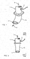
Fig. 1 is a perspective view showing a conventional example; -
Fig. 2 is a front view of the tailpipe shown inFig. 1 ; -
Fig. 3 is a view looking in a direction of arrows III inFig. 2 ; -
Fig. 4 is a perspective view showing an embodiment of the invention; -
Fig. 5 is a front view of the tailpipe shown inFig. 4 ; -
Fig. 6 is a view looking in a direction of arrows VI inFig. 5 ; -
Fig. 7 is a sectional view in a direction of arrows VII inFig. 5 ; -
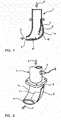
Fig. 8 is a perspective view showing a further embodiment of the invention; -
Fig. 9 is a front view of the tailpipe shown inFig. 8 ; -
Fig. 10 is a view looking in direction of arrows X inFig. 9 ; and -
Fig. 11 is a sectional view in a direction of arrows XI inFig. 9 . - Embodiments of the invention will be described in conjunction with the drawings.
-
Figs. 4-7 show an embodiment of the invention in which parts same as those inFigs. 1-3 are represented by same reference numerals. In the embodiment illustrated, a curved shape is employed just like the conventional example shown inFigs. 1-3 such that direct water hammer does not affect deep upon high-pressure washing of a vehicle body. Apartition 5 is mounted on an inner periphery of acurved portion 1a outward of a curved direction such that thepartition 5 is gradually spaced apart from the inner periphery toward downstream in a direction of flow ofexhaust gas 3 to thereby define adead end portion 6 between thepartition 5 and the inner periphery of thecurved portion 1a outward of the curved direction. - In this case, the
curved portion 1a is distended outward of the curved direction such that, in a condition without thepartition 5, a flow passage cross-sectional area at a defined position of thedead end portion 6 is larger than that upstream of thecurved portion 1a. Especially in the embodiment, thepartition 5 is provided in a position relationship as if it were along a contour of thecurved portion 1a of the conventional tailpipe 1 (seeFigs. 1-3 ) outward of the curved direction to thereby define thedead end portion 6 by the distended portion outward of the curved direction of thepartition 5. - It is ensured that the flow passage cross-sectional area decreased by the
partition 5 is larger than the opening cross-sectional area of theoutlet 4 of thetailpipe 1. Thus, in the embodiment, with thepartition 5 being added, ensured is a flow passage space substantially similar to that in the conventional example shown inFigs. 1-3 . - Arranged at a deep position upstream of the
curved portion 1a of thetailpipe 1 is asensor 2 for concentration-detection of particulates or particulate matter (PM) which can ascertain whether the particulates is properly reduced or not by a particulate filter (not shown) arranged further upstream. - Even if the washing water is sprayed toward the
outlet 4 of thetailpipe 1 as shown by arrows W inFigs. 6 and7 upon high-pressure washing of the vehicle body, owing to the structure, the washing water linearly ingressed through theoutlet 4 flows along the inner periphery of thecurved portion 1a, outward of the curved direction, of thetailpipe 1 and impinges on and is dammed by thedead end portion 6 defined by thepartition 5. Any splash upon the impingement is rebounded by thepartition 5 overlying. Thus, the ingress of the washing water into a deep position in thetailpipe 1 upon high-pressure washing of the vehicle body can be prevented. - The
partition 5 in thetailpipe 1 is arranged to be gradually spaced apart from the inner periphery of thecurved portion 1a outward of the curved direction toward downstream in the direction of flow of theexhaust gas 3 so that the flow of theexhaust gas 3 can be smoothly guided without hardship in the curved direction of thecurved portion 1a, thereby preliminarily preventing excessive pressure loss in the flow of theexhaust gas 3. - Especially, in the embodiment, the
curved portion 1a is distended outward of the curved direction such that, in the condition without thepartition 5, the flow passage cross-sectional area at the defined position of thedead end portion 6 is greater than that upstream of thecurved portion 1a. This causes no excessive decrease in the flow passage cross-sectional area of thetailpipe 1 by the addition of thepartition 5 and can ensure thedead end portion 6 large in size for damming the ingress of the washing water. Moreover, it is ensured that the flow passage cross-sectional area decreased by thepartition 5 is larger than an opening cross-sectional area of theoutlet 4 of thetailpipe 1, which can substantially suppress pressure loss in the flow of theexhaust gas 3 by the addition of thepartition 5. - Thus, the above embodiment can prevent the ingress of the washing water to the deep position in the
tailpipe 1 upon high-pressure washing of the vehicle body, so that thesensor 2, when arranged upstream of thecurved portion 1a of thetailpipe 1, can be protected from the washing water. Moreover, responsiveness in detection by thesensor 2 can be kept high since there is no need of a sensing element of thesensor 2 being covered with a splash-preventive cover. - The fact that the
curved portion 1a is distended outward of the curved direction such that, in the condition without thepartition 5, the flow passage cross-sectional area at the defined position of thedead end portion 6 is greater than that upstream of thecurved portion 1a can preliminarily prevent substantial increase in pressure loss due to excessive decrease of the flow passage cross-sectional area of thetailpipe 1 by the addition of thepartition 5 and can increase in size thedead end portion 6 to dam more reliably the ingress of the washing water. - The fact that the flow passage cross-sectional area decreased by the
partition 5 is ensured to be greater than the opening cross-sectional area of theoutlet 4 of thetailpipe 1 can substantially suppress pressure loss in the flow of theexhaust gas 3 by the addition of thepartition 5 to maintain exhaust performance as usual despite of the addition of thepartition 5. -
Figs. 8-11 shows a further embodiment of the invention. In the embodiment illustrated, just like the conventional example shown inFigs. 1-3 , a curved shape is employed such that direct water hammer does not affect deep upon high-pressure washing of a vehicle body. Adrainage opening 7 is opened at a position of acurved portion 1a outward of a curved direction and opposite to anoutlet 4 of atailpipe 1. Acover 9 is arranged to cover, in a spaced apart relationship, an outer periphery of thecurved portion 1a outward of the curved direction so as not to block thedrainage opening 7 and extends upstream in a scroll shape from a downstream end of thedrainage opening 7 to provide adrainage port 8 upstream of thedrainage opening 7. - Especially, in the embodiment, the curved shape is vertically imparted to the
tailpipe 1 such that the flow ofexhaust gas 3 from upward to downward is curved into a horizontal direction and is directed to theoutlet 4. Thecurved portion 1a is flattened toward theoutlet 4 of thetailpipe 1 to gradually decrease the flow passage cross-sectional area, whereby the ambient air can be taken through thedrainage port 8 due to an effect of reduced pressure resulting from increase in flow rate of theexhaust gas 3 to theoutlet 4. - Arranged at a deep position of the
tailpipe 1 upstream of thecurved portion 1a is asensor 2 for concentration-detection of particulates or particulate matter (PM). Arranged further upstream is a particulate filter (not shown) which ascertains whether the particulates are properly reduced or not. - Then, even if the washing water is sprayed to the
outlet 4 of thetailpipe 1 as shown by arrows W inFigs. 10 and11 upon high-pressure washing of the vehicle body, owing to the structure, the washing water linearly ingressed through theoutlet 4 passes through thedrainage opening 7 to the inner periphery of thecover 9, flows along the inner periphery of thecover 9 between the same and the outer periphery of thetailpipe 1 and is discharged outside of thetailpipe 1 through thedrainage port 8 substantially away from theoutlet 4, which prevents ingress of the washing water to a deep position in thetailpipe 1 upon high-pressure washing of the vehicle body. - In this case, since the
cover 9 extends upstream in the scroll shape from the downstream end of thedrainage opening 7, the washing water linearly ingressed through theoutlet 4 of thetailpipe 1 smoothly flows along the inner periphery of thetailpipe 1 outward of the curved direction as well as the inner periphery of thecover 9, which are continuous surfaces without steps, and readily reaches and is discharged through thedrainage port 8 without greatly losing power, thereby preliminarily preventing a situation that great splash is caused by violent impingement of the washing water against wall surfaces. - The
drainage opening 7 of thetailpipe 1 is covered with thecover 9 to prevent ingress of the washing water and the splash and thedrainage port 8 defined by thecover 9 is opened at the position substantially spaced apart upstream from theoutlet 4 of thetailpipe 1. Thus, even in the situation of the ingress of the washing water into theoutlet 4 of thetailpipe 1 upon the high-pressure washing, the ingress to thedrainage port 8 is hard to occur; even if the ingress of the washing water into thedrainage port 8 is caused, there is no fear that the washing water then flows round toward upstream again through thedownstream drainage opening 7. - Especially, in the embodiment, the curved shape is vertically imparted to the
tailpipe 1 such that the flow of theexhaust gas 3 from upward to downward is curved into the horizontal direction and is directed to theoutlet 4, so that the washing water remaining in thecover 9 at the end of the high-pressure washing flows down due to gravity and is certainly discharged through theoutlet 4. - Moreover, the flow passage cross-sectional area of the curved portion is gradually reduced toward the
outlet 4 of thetailpipe 1 such that the ambient air can be taken into thetailpipe 1 through thedrainage port 8 due to the effect of reduced pressure resulting from the increase in flow rate of theexhaust gas 3 to theoutlet 4, so that the ambient air is taken through thedrainage port 8 as theexhaust gas 3 flows through thetailpipe 1; such admixing of the ambient air lowers a temperature of theexhaust gas 3. - Thus, according to the above-mentioned embodiment, the ingress of the washing water to a deep position of the
tailpipe 1 upon high-pressure washing of vehicle body can be prevented so that thesensor 2, when arranged upstream of thecurved portion 1a of thetailpipe 1, can be protected from the washing water. Moreover, there is no need of a sensing element of thesensor 2 being covered with a splash-preventive cover, which can maintains high responsiveness in detection by thesensor 2. - At an end of the high-pressure washing, the washing water remaining in the
cover 9 flows down due to gravity and can be reliably discharged through theoutlet 4 of thetailpipe 1 so that production of rust and the like due to remaining of the washing water in thetailpipe 1 can be preliminarily prevented. Moreover, the ambient air can be taken through thedrainage port 8 into mixing with theexhaust gas 3 as theexhaust gas 3 flows through thetailpipe 1, thereby decreasing the temperature of theexhaust gas 3. This can enhance safeness against, for example, pedestrians passing by theoutlet 4 of thetailpipe 1 during stop of the vehicle. - It is to be understood that the water ingress prevention structure for the tailpipe according to the invention is not limited to the above embodiments and that various changes and modifications may be made without departing from the scope of the invention. For example, the exhaust emission control device upstream of the tailpipe is not restricted to that with the particulate filter and the selective reduction catalyst arranged in parallel with each other. The sensor on the tailpipe is not restricted to the sensor for the particulates or particulate matter (PM).
-
- 1
- tailpipe
- 1a
- curved portion
- 3
- exhaust gas
- 4
- outlet
- 5
- partition
- 6
- dead end portion
- 7
- drainage opening
- 8
- drainage port
- 9
- cover
Claims (6)
- A water ingress preventive structure for a tailpipe (1) for discharge of exhaust gas (3) outside of a vehicle at a terminal of an exhaust passage system, a curved shape being imparted to said tailpipe (1), comprising a partition (5) mounted on an inner periphery of a curved portion (1a) , outward of a curved direction, of said tailpipe (1) so as to be gradually spaced apart from said inner periphery toward downstream in a direction of flow of the exhaust gas (3), whereby a dead end portion (6) is defined by said partition (5) and said inner periphery of the curved portion (1a) outward of the curved direction.
- The water ingress preventive structure for the tailpipe (1) as claimed in claim 1, wherein said curved portion (1a) is distended outward of the curved direction such that, in a condition without the partition (5), a flow passage cross-sectional area at a defined position of the dead end portion (6) is larger than that upstream of the curved portion (1a) .
- The water ingress preventive structure for the tailpipe (1) as claimed in claim 1 or 2 wherein the flow passage cross-sectional area decreased by the partition (5) is larger than an opening cross-sectional area of an outlet (4) of the tailpipe (1).
- A water ingress preventive structure for a tailpipe (1) for discharge of exhaust gas (3) outside of a vehicle at a terminal of an exhaust passage system, a curved shape being imparted to the tailpipe (1), comprising a drainage opening (7) on a curved portion (1a) of the tailpipe (1) at a position outward of a curved direction and opposite to an outlet (4) of said tailpipe (1) and a cover (9) for covering, in a spaced-apart relationship, an outer periphery of said curved portion (1a) outward of the curved direction so as not to block said drainage opening (7), said cover (9) extending upstream in a scroll shape from a downstream end of said drainage opening (7) to open a drainage port (8) upstream of said drainage opening (7).
- The water ingress preventive structure for the tailpipe (1) as claimed in claim 4, wherein the curved shape is vertically imparted to the tailpipe (1) such that the flow of the exhaust gas (3) from upward to downward is curved into a horizontal direction and is directed to the outlet (4).
- The water ingress preventive structure for the tailpipe (1) as claimed in claim 4 or 5, wherein the flow passage cross-sectional area of the curved portion (1a) is gradually reduced toward the outlet (4) of the tailpipe (1) such that ambient air can be taken into the tailpipe (1) through the drainage port (8) due to an effect of reduced pressure resulting from increase in flow rate of the exhaust gas (3) directed to said outlet (4).
Applications Claiming Priority (3)
| Application Number | Priority Date | Filing Date | Title |
|---|---|---|---|
| JP2015012107A JP6453084B2 (en) | 2015-01-26 | 2015-01-26 | Tail pipe water entry prevention structure |
| JP2015013823A JP6453085B2 (en) | 2015-01-28 | 2015-01-28 | Tail pipe water entry prevention structure |
| PCT/JP2016/051873 WO2016121649A1 (en) | 2015-01-26 | 2016-01-22 | Water ingress preventing structure for tailpipe |
Publications (3)
| Publication Number | Publication Date |
|---|---|
| EP3252282A1 true EP3252282A1 (en) | 2017-12-06 |
| EP3252282A4 EP3252282A4 (en) | 2018-07-11 |
| EP3252282B1 EP3252282B1 (en) | 2019-06-26 |
Family
ID=56543262
Family Applications (1)
| Application Number | Title | Priority Date | Filing Date |
|---|---|---|---|
| EP16743252.5A Active EP3252282B1 (en) | 2015-01-26 | 2016-01-22 | Tailpipe with water ingress preventing structure |
Country Status (4)
| Country | Link |
|---|---|
| US (1) | US10309288B2 (en) |
| EP (1) | EP3252282B1 (en) |
| CN (1) | CN107208524B (en) |
| WO (1) | WO2016121649A1 (en) |
Families Citing this family (6)
| Publication number | Priority date | Publication date | Assignee | Title |
|---|---|---|---|---|
| US10150438B2 (en) * | 2017-05-03 | 2018-12-11 | Nissan North America, Inc. | Rear exhaust finisher assembly |
| JP6717867B2 (en) * | 2017-11-06 | 2020-07-08 | 株式会社三五 | Vehicle exhaust system |
| WO2019188801A1 (en) * | 2018-03-27 | 2019-10-03 | 本田技研工業株式会社 | Exhaust muffler |
| US10934907B2 (en) | 2019-03-20 | 2021-03-02 | Caterpillar Inc. | Outlet for exhaust gas aftertreatment module |
| CN111266208A (en) * | 2020-03-29 | 2020-06-12 | 陆建强 | Flue gas extremely-cold spray gun of hazardous waste disposal center |
| US11828215B1 (en) * | 2022-12-21 | 2023-11-28 | Thermo King Llc | Self-cleaning prime mover exhaust system and method |
Family Cites Families (18)
| Publication number | Priority date | Publication date | Assignee | Title |
|---|---|---|---|---|
| FR1238805A (en) * | 1959-07-07 | 1960-08-19 | Exhaust silencer for two-stroke engines | |
| JPS6115207Y2 (en) * | 1980-05-20 | 1986-05-12 | ||
| JPH0665847B2 (en) * | 1985-06-08 | 1994-08-24 | 三信工業株式会社 | Exhaust gas purification device for ship propulsion |
| JPH0673324U (en) * | 1993-03-29 | 1994-10-18 | 日野自動車工業株式会社 | Vertical exhaust pipe mounting structure |
| US6012285A (en) * | 1998-03-19 | 2000-01-11 | Wacker Corporation | Exhaust pipe with improved drain |
| US6478645B1 (en) * | 2001-09-06 | 2002-11-12 | Marine Power, Inc. | Moisture migration inhibitor for wet marine exhausts, and method therefore |
| JP2003314276A (en) * | 2002-04-25 | 2003-11-06 | Mitsubishi Heavy Ind Ltd | Exhaust tube and refrigerator vehicle provided therewith |
| JP4153744B2 (en) | 2002-07-29 | 2008-09-24 | ヤンマー株式会社 | Engine generator exhaust pipe structure |
| JP2009121310A (en) | 2007-11-14 | 2009-06-04 | Mitsubishi Fuso Truck & Bus Corp | Tail pipe structure of exhaust system of engine |
| US7987665B2 (en) * | 2008-09-08 | 2011-08-02 | Jafar Salamat | Exhaust evacuation apparatus |
| US8479501B2 (en) * | 2009-07-20 | 2013-07-09 | International Engine Intellectual Property Company, Llc | Exhaust cooling module for SCR catalysts |
| KR20120137150A (en) * | 2011-06-10 | 2012-12-20 | 현대자동차주식회사 | Automotive Tail Pipe Assemblies |
| KR101795373B1 (en) * | 2011-06-10 | 2017-11-09 | 현대자동차 주식회사 | Tail pipe assembly for vehicle |
| CN202391531U (en) * | 2011-12-20 | 2012-08-22 | 同济大学 | Automobile water-proof exhaust pipe |
| CN202707199U (en) * | 2012-04-28 | 2013-01-30 | 奉化市科锐汽车部件有限公司 | Anti-water flameout device of vent pipe of automobile |
| DE102014103602A1 (en) * | 2014-03-17 | 2015-09-17 | Thyssenkrupp Ag | Device for removing exhaust gases of a marine engine |
| CN103912384B (en) * | 2014-04-10 | 2016-05-25 | 杨永强 | One prevents automobile engine water inlet system |
| CN104033227A (en) * | 2014-06-11 | 2014-09-10 | 廖大涌 | Waterproof exhaust pipe |
-
2016
- 2016-01-22 US US15/521,024 patent/US10309288B2/en not_active Expired - Fee Related
- 2016-01-22 EP EP16743252.5A patent/EP3252282B1/en active Active
- 2016-01-22 WO PCT/JP2016/051873 patent/WO2016121649A1/en not_active Ceased
- 2016-01-22 CN CN201680007292.9A patent/CN107208524B/en not_active Expired - Fee Related
Also Published As
| Publication number | Publication date |
|---|---|
| US20170370270A1 (en) | 2017-12-28 |
| US10309288B2 (en) | 2019-06-04 |
| EP3252282B1 (en) | 2019-06-26 |
| CN107208524B (en) | 2019-06-25 |
| EP3252282A4 (en) | 2018-07-11 |
| CN107208524A (en) | 2017-09-26 |
| WO2016121649A1 (en) | 2016-08-04 |
Similar Documents
| Publication | Publication Date | Title |
|---|---|---|
| EP3252282B1 (en) | Tailpipe with water ingress preventing structure | |
| EP2204556B1 (en) | Exhaust emission control device | |
| EP2295756B1 (en) | Exhaust emission control device | |
| JP6453085B2 (en) | Tail pipe water entry prevention structure | |
| EP2192284B1 (en) | Exhaust emission control device | |
| EP2184455B1 (en) | Injector mounting structure | |
| EP2128398B1 (en) | Exhaust emission control device | |
| US5321215A (en) | Vertical exhaust system incorporating a water trap | |
| EP2518287A1 (en) | Exhaust purification device | |
| BRPI1003716A2 (en) | device for cooling an exhaust gas stream, and motor vehicle | |
| US6802387B1 (en) | Muffler with external water trap | |
| EP3168440A1 (en) | Mixing structure | |
| EP2549069A1 (en) | Exhaust gas purification device | |
| CA2467474A1 (en) | Automobile muffler | |
| CN113794026A (en) | New forms of energy electric motor car power battery group safety coefficient | |
| JP6453084B2 (en) | Tail pipe water entry prevention structure | |
| WO2012158022A1 (en) | Exhaust system for a diesel engine | |
| KR101797614B1 (en) | Scr reactor in ship or marin structure | |
| KR100488785B1 (en) | Apparatus for draining condensed water in an automobile muffler | |
| KR102206943B1 (en) | Exhaust gas system for improving performance and durability of SCR reactor | |
| JP2010216460A (en) | Exhaust system | |
| CN207535647U (en) | Gutter channel return-air labyrinth damping structure | |
| CN202325769U (en) | Spark blow-out silencer used for vehicle | |
| KR102693524B1 (en) | Condensate removal device for Exhaust Gas Recirculation valve | |
| KR20170006853A (en) | Structure for preventing back flow of diesel exhaust system |
Legal Events
| Date | Code | Title | Description |
|---|---|---|---|
| STAA | Information on the status of an ep patent application or granted ep patent |
Free format text: STATUS: THE INTERNATIONAL PUBLICATION HAS BEEN MADE |
|
| PUAI | Public reference made under article 153(3) epc to a published international application that has entered the european phase |
Free format text: ORIGINAL CODE: 0009012 |
|
| STAA | Information on the status of an ep patent application or granted ep patent |
Free format text: STATUS: REQUEST FOR EXAMINATION WAS MADE |
|
| 17P | Request for examination filed |
Effective date: 20170412 |
|
| AK | Designated contracting states |
Kind code of ref document: A1 Designated state(s): AL AT BE BG CH CY CZ DE DK EE ES FI FR GB GR HR HU IE IS IT LI LT LU LV MC MK MT NL NO PL PT RO RS SE SI SK SM TR |
|
| AX | Request for extension of the european patent |
Extension state: BA ME |
|
| DAV | Request for validation of the european patent (deleted) | ||
| DAX | Request for extension of the european patent (deleted) | ||
| RIC1 | Information provided on ipc code assigned before grant |
Ipc: F01N 13/00 20100101AFI20180531BHEP Ipc: F01N 13/08 20100101ALI20180531BHEP Ipc: F01N 13/20 20100101ALI20180531BHEP |
|
| A4 | Supplementary search report drawn up and despatched |
Effective date: 20180608 |
|
| STAA | Information on the status of an ep patent application or granted ep patent |
Free format text: STATUS: EXAMINATION IS IN PROGRESS |
|
| 17Q | First examination report despatched |
Effective date: 20181122 |
|
| GRAP | Despatch of communication of intention to grant a patent |
Free format text: ORIGINAL CODE: EPIDOSNIGR1 |
|
| STAA | Information on the status of an ep patent application or granted ep patent |
Free format text: STATUS: GRANT OF PATENT IS INTENDED |
|
| INTG | Intention to grant announced |
Effective date: 20190207 |
|
| GRAS | Grant fee paid |
Free format text: ORIGINAL CODE: EPIDOSNIGR3 |
|
| GRAA | (expected) grant |
Free format text: ORIGINAL CODE: 0009210 |
|
| STAA | Information on the status of an ep patent application or granted ep patent |
Free format text: STATUS: THE PATENT HAS BEEN GRANTED |
|
| AK | Designated contracting states |
Kind code of ref document: B1 Designated state(s): AL AT BE BG CH CY CZ DE DK EE ES FI FR GB GR HR HU IE IS IT LI LT LU LV MC MK MT NL NO PL PT RO RS SE SI SK SM TR |
|
| REG | Reference to a national code |
Ref country code: GB Ref legal event code: FG4D |
|
| REG | Reference to a national code |
Ref country code: CH Ref legal event code: EP |
|
| REG | Reference to a national code |
Ref country code: AT Ref legal event code: REF Ref document number: 1148533 Country of ref document: AT Kind code of ref document: T Effective date: 20190715 |
|
| REG | Reference to a national code |
Ref country code: DE Ref legal event code: R096 Ref document number: 602016015969 Country of ref document: DE |
|
| REG | Reference to a national code |
Ref country code: IE Ref legal event code: FG4D |
|
| REG | Reference to a national code |
Ref country code: NL Ref legal event code: MP Effective date: 20190626 |
|
| PG25 | Lapsed in a contracting state [announced via postgrant information from national office to epo] |
Ref country code: LT Free format text: LAPSE BECAUSE OF FAILURE TO SUBMIT A TRANSLATION OF THE DESCRIPTION OR TO PAY THE FEE WITHIN THE PRESCRIBED TIME-LIMIT Effective date: 20190626 Ref country code: HR Free format text: LAPSE BECAUSE OF FAILURE TO SUBMIT A TRANSLATION OF THE DESCRIPTION OR TO PAY THE FEE WITHIN THE PRESCRIBED TIME-LIMIT Effective date: 20190626 Ref country code: SE Free format text: LAPSE BECAUSE OF FAILURE TO SUBMIT A TRANSLATION OF THE DESCRIPTION OR TO PAY THE FEE WITHIN THE PRESCRIBED TIME-LIMIT Effective date: 20190626 Ref country code: FI Free format text: LAPSE BECAUSE OF FAILURE TO SUBMIT A TRANSLATION OF THE DESCRIPTION OR TO PAY THE FEE WITHIN THE PRESCRIBED TIME-LIMIT Effective date: 20190626 Ref country code: NO Free format text: LAPSE BECAUSE OF FAILURE TO SUBMIT A TRANSLATION OF THE DESCRIPTION OR TO PAY THE FEE WITHIN THE PRESCRIBED TIME-LIMIT Effective date: 20190926 Ref country code: AL Free format text: LAPSE BECAUSE OF FAILURE TO SUBMIT A TRANSLATION OF THE DESCRIPTION OR TO PAY THE FEE WITHIN THE PRESCRIBED TIME-LIMIT Effective date: 20190626 |
|
| REG | Reference to a national code |
Ref country code: LT Ref legal event code: MG4D |
|
| PG25 | Lapsed in a contracting state [announced via postgrant information from national office to epo] |
Ref country code: BG Free format text: LAPSE BECAUSE OF FAILURE TO SUBMIT A TRANSLATION OF THE DESCRIPTION OR TO PAY THE FEE WITHIN THE PRESCRIBED TIME-LIMIT Effective date: 20190926 Ref country code: GR Free format text: LAPSE BECAUSE OF FAILURE TO SUBMIT A TRANSLATION OF THE DESCRIPTION OR TO PAY THE FEE WITHIN THE PRESCRIBED TIME-LIMIT Effective date: 20190927 Ref country code: RS Free format text: LAPSE BECAUSE OF FAILURE TO SUBMIT A TRANSLATION OF THE DESCRIPTION OR TO PAY THE FEE WITHIN THE PRESCRIBED TIME-LIMIT Effective date: 20190626 Ref country code: LV Free format text: LAPSE BECAUSE OF FAILURE TO SUBMIT A TRANSLATION OF THE DESCRIPTION OR TO PAY THE FEE WITHIN THE PRESCRIBED TIME-LIMIT Effective date: 20190626 |
|
| REG | Reference to a national code |
Ref country code: AT Ref legal event code: MK05 Ref document number: 1148533 Country of ref document: AT Kind code of ref document: T Effective date: 20190626 |
|
| PG25 | Lapsed in a contracting state [announced via postgrant information from national office to epo] |
Ref country code: PT Free format text: LAPSE BECAUSE OF FAILURE TO SUBMIT A TRANSLATION OF THE DESCRIPTION OR TO PAY THE FEE WITHIN THE PRESCRIBED TIME-LIMIT Effective date: 20191028 Ref country code: AT Free format text: LAPSE BECAUSE OF FAILURE TO SUBMIT A TRANSLATION OF THE DESCRIPTION OR TO PAY THE FEE WITHIN THE PRESCRIBED TIME-LIMIT Effective date: 20190626 Ref country code: NL Free format text: LAPSE BECAUSE OF FAILURE TO SUBMIT A TRANSLATION OF THE DESCRIPTION OR TO PAY THE FEE WITHIN THE PRESCRIBED TIME-LIMIT Effective date: 20190626 Ref country code: EE Free format text: LAPSE BECAUSE OF FAILURE TO SUBMIT A TRANSLATION OF THE DESCRIPTION OR TO PAY THE FEE WITHIN THE PRESCRIBED TIME-LIMIT Effective date: 20190626 Ref country code: SK Free format text: LAPSE BECAUSE OF FAILURE TO SUBMIT A TRANSLATION OF THE DESCRIPTION OR TO PAY THE FEE WITHIN THE PRESCRIBED TIME-LIMIT Effective date: 20190626 Ref country code: RO Free format text: LAPSE BECAUSE OF FAILURE TO SUBMIT A TRANSLATION OF THE DESCRIPTION OR TO PAY THE FEE WITHIN THE PRESCRIBED TIME-LIMIT Effective date: 20190626 Ref country code: CZ Free format text: LAPSE BECAUSE OF FAILURE TO SUBMIT A TRANSLATION OF THE DESCRIPTION OR TO PAY THE FEE WITHIN THE PRESCRIBED TIME-LIMIT Effective date: 20190626 |
|
| PG25 | Lapsed in a contracting state [announced via postgrant information from national office to epo] |
Ref country code: ES Free format text: LAPSE BECAUSE OF FAILURE TO SUBMIT A TRANSLATION OF THE DESCRIPTION OR TO PAY THE FEE WITHIN THE PRESCRIBED TIME-LIMIT Effective date: 20190626 Ref country code: SM Free format text: LAPSE BECAUSE OF FAILURE TO SUBMIT A TRANSLATION OF THE DESCRIPTION OR TO PAY THE FEE WITHIN THE PRESCRIBED TIME-LIMIT Effective date: 20190626 Ref country code: IS Free format text: LAPSE BECAUSE OF FAILURE TO SUBMIT A TRANSLATION OF THE DESCRIPTION OR TO PAY THE FEE WITHIN THE PRESCRIBED TIME-LIMIT Effective date: 20191026 Ref country code: IT Free format text: LAPSE BECAUSE OF FAILURE TO SUBMIT A TRANSLATION OF THE DESCRIPTION OR TO PAY THE FEE WITHIN THE PRESCRIBED TIME-LIMIT Effective date: 20190626 |
|
| PG25 | Lapsed in a contracting state [announced via postgrant information from national office to epo] |
Ref country code: TR Free format text: LAPSE BECAUSE OF FAILURE TO SUBMIT A TRANSLATION OF THE DESCRIPTION OR TO PAY THE FEE WITHIN THE PRESCRIBED TIME-LIMIT Effective date: 20190626 |
|
| PG25 | Lapsed in a contracting state [announced via postgrant information from national office to epo] |
Ref country code: DK Free format text: LAPSE BECAUSE OF FAILURE TO SUBMIT A TRANSLATION OF THE DESCRIPTION OR TO PAY THE FEE WITHIN THE PRESCRIBED TIME-LIMIT Effective date: 20190626 Ref country code: PL Free format text: LAPSE BECAUSE OF FAILURE TO SUBMIT A TRANSLATION OF THE DESCRIPTION OR TO PAY THE FEE WITHIN THE PRESCRIBED TIME-LIMIT Effective date: 20190626 |
|
| PGFP | Annual fee paid to national office [announced via postgrant information from national office to epo] |
Ref country code: DE Payment date: 20191219 Year of fee payment: 5 Ref country code: GB Payment date: 20191223 Year of fee payment: 5 |
|
| PG25 | Lapsed in a contracting state [announced via postgrant information from national office to epo] |
Ref country code: IS Free format text: LAPSE BECAUSE OF FAILURE TO SUBMIT A TRANSLATION OF THE DESCRIPTION OR TO PAY THE FEE WITHIN THE PRESCRIBED TIME-LIMIT Effective date: 20200224 |
|
| REG | Reference to a national code |
Ref country code: DE Ref legal event code: R097 Ref document number: 602016015969 Country of ref document: DE |
|
| PLBE | No opposition filed within time limit |
Free format text: ORIGINAL CODE: 0009261 |
|
| STAA | Information on the status of an ep patent application or granted ep patent |
Free format text: STATUS: NO OPPOSITION FILED WITHIN TIME LIMIT |
|
| PG2D | Information on lapse in contracting state deleted |
Ref country code: IS |
|
| 26N | No opposition filed |
Effective date: 20200603 |
|
| PG25 | Lapsed in a contracting state [announced via postgrant information from national office to epo] |
Ref country code: SI Free format text: LAPSE BECAUSE OF FAILURE TO SUBMIT A TRANSLATION OF THE DESCRIPTION OR TO PAY THE FEE WITHIN THE PRESCRIBED TIME-LIMIT Effective date: 20190626 Ref country code: MC Free format text: LAPSE BECAUSE OF FAILURE TO SUBMIT A TRANSLATION OF THE DESCRIPTION OR TO PAY THE FEE WITHIN THE PRESCRIBED TIME-LIMIT Effective date: 20190626 |
|
| REG | Reference to a national code |
Ref country code: CH Ref legal event code: PL |
|
| REG | Reference to a national code |
Ref country code: BE Ref legal event code: MM Effective date: 20200131 |
|
| PG25 | Lapsed in a contracting state [announced via postgrant information from national office to epo] |
Ref country code: LU Free format text: LAPSE BECAUSE OF NON-PAYMENT OF DUE FEES Effective date: 20200122 Ref country code: FR Free format text: LAPSE BECAUSE OF NON-PAYMENT OF DUE FEES Effective date: 20200131 |
|
| PG25 | Lapsed in a contracting state [announced via postgrant information from national office to epo] |
Ref country code: BE Free format text: LAPSE BECAUSE OF NON-PAYMENT OF DUE FEES Effective date: 20200131 Ref country code: CH Free format text: LAPSE BECAUSE OF NON-PAYMENT OF DUE FEES Effective date: 20200131 Ref country code: LI Free format text: LAPSE BECAUSE OF NON-PAYMENT OF DUE FEES Effective date: 20200131 |
|
| PG25 | Lapsed in a contracting state [announced via postgrant information from national office to epo] |
Ref country code: IE Free format text: LAPSE BECAUSE OF NON-PAYMENT OF DUE FEES Effective date: 20200122 |
|
| REG | Reference to a national code |
Ref country code: DE Ref legal event code: R119 Ref document number: 602016015969 Country of ref document: DE |
|
| GBPC | Gb: european patent ceased through non-payment of renewal fee |
Effective date: 20210122 |
|
| PG25 | Lapsed in a contracting state [announced via postgrant information from national office to epo] |
Ref country code: DE Free format text: LAPSE BECAUSE OF NON-PAYMENT OF DUE FEES Effective date: 20210803 Ref country code: GB Free format text: LAPSE BECAUSE OF NON-PAYMENT OF DUE FEES Effective date: 20210122 |
|
| PG25 | Lapsed in a contracting state [announced via postgrant information from national office to epo] |
Ref country code: MT Free format text: LAPSE BECAUSE OF FAILURE TO SUBMIT A TRANSLATION OF THE DESCRIPTION OR TO PAY THE FEE WITHIN THE PRESCRIBED TIME-LIMIT Effective date: 20190626 Ref country code: CY Free format text: LAPSE BECAUSE OF FAILURE TO SUBMIT A TRANSLATION OF THE DESCRIPTION OR TO PAY THE FEE WITHIN THE PRESCRIBED TIME-LIMIT Effective date: 20190626 |
|
| PG25 | Lapsed in a contracting state [announced via postgrant information from national office to epo] |
Ref country code: MK Free format text: LAPSE BECAUSE OF FAILURE TO SUBMIT A TRANSLATION OF THE DESCRIPTION OR TO PAY THE FEE WITHIN THE PRESCRIBED TIME-LIMIT Effective date: 20190626 |