EP3251991A1 - Image forming apparatus - Google Patents
Image forming apparatus Download PDFInfo
- Publication number
- EP3251991A1 EP3251991A1 EP17161471.2A EP17161471A EP3251991A1 EP 3251991 A1 EP3251991 A1 EP 3251991A1 EP 17161471 A EP17161471 A EP 17161471A EP 3251991 A1 EP3251991 A1 EP 3251991A1
- Authority
- EP
- European Patent Office
- Prior art keywords
- roller
- receiving medium
- image receiving
- image
- forming apparatus
- Prior art date
- Legal status (The legal status is an assumption and is not a legal conclusion. Google has not performed a legal analysis and makes no representation as to the accuracy of the status listed.)
- Withdrawn
Links
Images


Classifications
-
- B—PERFORMING OPERATIONS; TRANSPORTING
- B65—CONVEYING; PACKING; STORING; HANDLING THIN OR FILAMENTARY MATERIAL
- B65H—HANDLING THIN OR FILAMENTARY MATERIAL, e.g. SHEETS, WEBS, CABLES
- B65H29/00—Delivering or advancing articles from machines; Advancing articles to or into piles
- B65H29/12—Delivering or advancing articles from machines; Advancing articles to or into piles by means of the nip between two, or between two sets of, moving tapes or bands or rollers
- B65H29/14—Delivering or advancing articles from machines; Advancing articles to or into piles by means of the nip between two, or between two sets of, moving tapes or bands or rollers and introducing into a pile
-
- G—PHYSICS
- G03—PHOTOGRAPHY; CINEMATOGRAPHY; ANALOGOUS TECHNIQUES USING WAVES OTHER THAN OPTICAL WAVES; ELECTROGRAPHY; HOLOGRAPHY
- G03G—ELECTROGRAPHY; ELECTROPHOTOGRAPHY; MAGNETOGRAPHY
- G03G15/00—Apparatus for electrographic processes using a charge pattern
- G03G15/20—Apparatus for electrographic processes using a charge pattern for fixing, e.g. by using heat
- G03G15/2003—Apparatus for electrographic processes using a charge pattern for fixing, e.g. by using heat using heat
- G03G15/2014—Apparatus for electrographic processes using a charge pattern for fixing, e.g. by using heat using heat using contact heat
- G03G15/2053—Structural details of heat elements, e.g. structure of roller or belt, eddy current, induction heating
-
- B—PERFORMING OPERATIONS; TRANSPORTING
- B65—CONVEYING; PACKING; STORING; HANDLING THIN OR FILAMENTARY MATERIAL
- B65H—HANDLING THIN OR FILAMENTARY MATERIAL, e.g. SHEETS, WEBS, CABLES
- B65H29/00—Delivering or advancing articles from machines; Advancing articles to or into piles
- B65H29/70—Article bending or stiffening arrangements
-
- G—PHYSICS
- G03—PHOTOGRAPHY; CINEMATOGRAPHY; ANALOGOUS TECHNIQUES USING WAVES OTHER THAN OPTICAL WAVES; ELECTROGRAPHY; HOLOGRAPHY
- G03G—ELECTROGRAPHY; ELECTROPHOTOGRAPHY; MAGNETOGRAPHY
- G03G15/00—Apparatus for electrographic processes using a charge pattern
- G03G15/65—Apparatus which relate to the handling of copy material
- G03G15/6555—Handling of sheet copy material taking place in a specific part of the copy material feeding path
- G03G15/6573—Feeding path after the fixing point and up to the discharge tray or the finisher, e.g. special treatment of copy material to compensate for effects from the fixing
- G03G15/6576—Decurling of sheet material
-
- B—PERFORMING OPERATIONS; TRANSPORTING
- B65—CONVEYING; PACKING; STORING; HANDLING THIN OR FILAMENTARY MATERIAL
- B65H—HANDLING THIN OR FILAMENTARY MATERIAL, e.g. SHEETS, WEBS, CABLES
- B65H2301/00—Handling processes for sheets or webs
- B65H2301/50—Auxiliary process performed during handling process
- B65H2301/51—Modifying a characteristic of handled material
- B65H2301/512—Changing form of handled material
- B65H2301/5121—Bending, buckling, curling, bringing a curvature
- B65H2301/51214—Bending, buckling, curling, bringing a curvature parallel to direction of displacement of handled material
-
- B—PERFORMING OPERATIONS; TRANSPORTING
- B65—CONVEYING; PACKING; STORING; HANDLING THIN OR FILAMENTARY MATERIAL
- B65H—HANDLING THIN OR FILAMENTARY MATERIAL, e.g. SHEETS, WEBS, CABLES
- B65H2301/00—Handling processes for sheets or webs
- B65H2301/50—Auxiliary process performed during handling process
- B65H2301/51—Modifying a characteristic of handled material
- B65H2301/512—Changing form of handled material
- B65H2301/5122—Corrugating; Stiffening
-
- B—PERFORMING OPERATIONS; TRANSPORTING
- B65—CONVEYING; PACKING; STORING; HANDLING THIN OR FILAMENTARY MATERIAL
- B65H—HANDLING THIN OR FILAMENTARY MATERIAL, e.g. SHEETS, WEBS, CABLES
- B65H2301/00—Handling processes for sheets or webs
- B65H2301/50—Auxiliary process performed during handling process
- B65H2301/51—Modifying a characteristic of handled material
- B65H2301/512—Changing form of handled material
- B65H2301/5125—Restoring form
- B65H2301/51256—Removing waviness or curl, smoothing
-
- B—PERFORMING OPERATIONS; TRANSPORTING
- B65—CONVEYING; PACKING; STORING; HANDLING THIN OR FILAMENTARY MATERIAL
- B65H—HANDLING THIN OR FILAMENTARY MATERIAL, e.g. SHEETS, WEBS, CABLES
- B65H2404/00—Parts for transporting or guiding the handled material
- B65H2404/10—Rollers
- B65H2404/13—Details of longitudinal profile
- B65H2404/131—Details of longitudinal profile shape
- B65H2404/1313—Details of longitudinal profile shape concave
-
- B—PERFORMING OPERATIONS; TRANSPORTING
- B65—CONVEYING; PACKING; STORING; HANDLING THIN OR FILAMENTARY MATERIAL
- B65H—HANDLING THIN OR FILAMENTARY MATERIAL, e.g. SHEETS, WEBS, CABLES
- B65H2801/00—Application field
- B65H2801/24—Post -processing devices
- B65H2801/27—Devices located downstream of office-type machines
-
- G—PHYSICS
- G03—PHOTOGRAPHY; CINEMATOGRAPHY; ANALOGOUS TECHNIQUES USING WAVES OTHER THAN OPTICAL WAVES; ELECTROGRAPHY; HOLOGRAPHY
- G03G—ELECTROGRAPHY; ELECTROPHOTOGRAPHY; MAGNETOGRAPHY
- G03G2215/00—Apparatus for electrophotographic processes
- G03G2215/00362—Apparatus for electrophotographic processes relating to the copy medium handling
- G03G2215/00535—Stable handling of copy medium
- G03G2215/00662—Decurling device
-
- G—PHYSICS
- G03—PHOTOGRAPHY; CINEMATOGRAPHY; ANALOGOUS TECHNIQUES USING WAVES OTHER THAN OPTICAL WAVES; ELECTROGRAPHY; HOLOGRAPHY
- G03G—ELECTROGRAPHY; ELECTROPHOTOGRAPHY; MAGNETOGRAPHY
- G03G2215/00—Apparatus for electrophotographic processes
- G03G2215/01—Apparatus for electrophotographic processes for producing multicoloured copies
- G03G2215/0103—Plural electrographic recording members
- G03G2215/0119—Linear arrangement adjacent plural transfer points
- G03G2215/0122—Linear arrangement adjacent plural transfer points primary transfer to an intermediate transfer belt
- G03G2215/0125—Linear arrangement adjacent plural transfer points primary transfer to an intermediate transfer belt the linear arrangement being horizontal or slanted
- G03G2215/0132—Linear arrangement adjacent plural transfer points primary transfer to an intermediate transfer belt the linear arrangement being horizontal or slanted vertical medium transport path at the secondary transfer
Definitions
- the present invention generally relates to the field of image forming technologies and embodiments described herein relate particularly to an image forming apparatus, a system comprising the corresponding and to reducing damage to an image receiving medium at the time of discharging a sheet.
- An image forming apparatus discharges an image receiving medium passing through a fixing device to a discharge tray via a sheet discharge roller (for example, Japanese Unexamined Patent Application Publication No. 2007-217187 ).
- the image receiving medium is easily curved in a rotation direction of the fixing device through being pressurized and heated by the fixing device. If the image receiving medium in a curled state is discharged to the discharge tray, the image receiving medium curls and the loading property of the image receiving medium deteriorates.
- a correction member for correcting the curl of the image receiving medium is arranged at a mechanism part of the sheet discharge roller for discharging the image receiving medium to the discharge tray.
- the image receiving medium is damaged, for example, streaks are generated on the image receiving medium.
- an image forming apparatus comprising:
- the image forming apparatus further comprises:
- the image forming apparatus further comprises a driven roller the outer peripheral surface of which is a flat surface in the first direction.
- the image forming apparatus further comprises:
- the image forming apparatus further comprises:
- the image forming apparatus further comprises:
- the protrusion comprises a roller.
- the protrusion is configured to bend the image receiving medium in an out-of-surface direction to suppress curling.
- the protrusion is positioned coaxial with the driven roller.
- the protrusion is positioned so not to be coaxial with the driven roller.
- the invention also relates to an image forming system, comprising:
- the invention further relates to a method of reducing curl after forming an image on an image receiving medium, comprising:
- the invention also concerns a method of reducing streaks after forming an image on an image receiving medium, comprising:
- a contact pressure at an end of the driving roller with the image receiving medium is larger than a contact pressure at a center part of the driving roller with the image receiving medium.
- an image forming apparatus comprises a conveyance path, a fixing device, a first roller, an axis, a second roller and a protrusion.
- the conveyance path conveys an image receiving medium.
- the fixing device fixes an image formed on the image receiving medium.
- the first roller is arranged at the downstream side of a conveyance direction of the image receiving medium with respect to the fixing device.
- the axis is an axis of the first roller.
- the second roller faces the first roller and an end thereof protrudes towards a central part of the conveyance path with respect to an end of the first roller at the central part of the conveyance path in a first direction substantially parallel to the axis.
- the protrusion is arranged at the second roller side to protrude towards the first roller side from the second roller side and a protruding amount is greater than that of the second roller.
- Fig. 1 is a diagram illustrating an image forming apparatus 200.
- the image forming apparatus 200 reads a document on a document tray Rt by an automatic document feeder 9 with a scanning optical system 10.
- the image forming apparatus 200 has a cassette 11.
- the image receiving medium is placed in the cassette 11.
- the image forming medium is a sheet, an envelope, an OHP image recording medium and the like.
- the image forming apparatus 200 picks up the image receiving medium from the cassette 11 with pickup rollers 31 ⁇ 34 to convey the image receiving medium to a conveyance path 13.
- the conveyance path 13 is a passage that extends from the cassette 11 side to a discharge tray 37 side to convey the image receiving medium.
- the cassette 11 side is set to an upstream side with respect to the conveyance direction of the image receiving medium
- the discharge tray 37 side is set to a downstream side with respect to the conveyance direction.
- the image forming apparatus 200 conveys the image receiving medium picked up from the cassette 11 by the pickup rollers to a secondary transfer position U by a conveyance roller and a resist roller.
- the image forming apparatus 200 forms an electrostatic latent image on photoconductive drums 2Y ⁇ 2K (2Y, 2M, 2C and 2K, and other reference numerals are the same) by a laser optical system 30 based on image data of the document.
- the image forming apparatus 200 drives developing devices 3Y ⁇ 3K to develop the electrostatic latent images on the photoconductive drums 2Y ⁇ 2K with toner of Y ⁇ K to form toner images of Y ⁇ K on the photoconductive drums 2Y ⁇ 2K.
- the image forming apparatus 200 transfers the toner images of Y ⁇ K on the photoconductive drums 2Y ⁇ 2K onto a transfer belt 35 in the order of Y, M, C and K to form one color toner image on the transfer belt 35.
- the image forming apparatus 200 transfers the toner image on the transfer belt 35 onto the image receiving medium at the secondary transfer position U.
- the image forming apparatus 200 heats the image receiving medium at a fixing device 36.
- the fixing device 36 fixes the toner image on the image receiving medium.
- the fixing device 36 has a heat source.
- the fixing device 36 has a heat roller 361 which is heated by the heat source and a pressure roller 362 which pressurizes the heat roller 361.
- the heat roller 361 is arranged at the transfer belt 35 side between two sides of the conveyance path 13 which face each other across the image receiving medium.
- the heat roller 361 heats a surface side of the image receiving medium where the toner image is formed at the time of a simplex printing.
- the type of the heat source is not limited.
- the heat source may be constituted by a lamp heater such as a halogen lamp or a resistance heating body such as a thermal head.
- the heat source may also be an IH (induction heating) type heater.
- the image discharge apparatus 200 discharges the image receiving medium after a fixing processing by the sheet discharge roller 4 to the discharge tray 37.
- Fig. 2 is a diagram illustrating the constitution of the sheet discharge roller 4.
- the sheet discharge roller 4 is a roller for conveying the image receiving medium to the discharge tray 37.
- the sheet discharge roller 4 is provided at the conveyance direction downstream side of the fixing device 36 and at the conveyance direction upstream side of the discharge tray 37.
- the sheet discharge roller 4 is provided in the vicinity of the discharge tray 37.
- the image receiving medium is discharged to the discharge tray 37 by the sheet discharge roller 4.
- the sheet discharge roller 4 has a plurality of roller pairs 5.
- the sheet discharge roller 4 has a plurality of rollers for correction 6 (protrusion).
- the sheet discharge roller 4 also has a drive axis 71 and an axis 72 as the axes of the roller pair 5.
- an axial direction of the sheet discharge roller 4 (direction substantially parallel to the drive axis 71) is set to a first direction and a direction orthogonal to the first direction is set to a second direction.
- the sheet discharge roller 4 has the function of correcting the curl of the image receiving medium. If the image receiving medium passes through the fixing device 36, since the image receiving medium receives heat and pressure from the fixing device 36, the image receiving medium sometimes curls. If the image receiving medium is discharged to the discharge tray 37 in a curled state, the loading property of the image receiving medium is impaired. Therefore, the sheet discharge roller 4 corrects the curl of the image receiving medium by bending the image receiving medium towards the second direction orthogonal to the axial direction of the sheet discharge roller 4.
- the plurality of roller pairs 5 is positioned at intervals in the first direction orthogonal to the conveyance direction of the image receiving medium.
- a first roller pair 5A includes a driving roller 51A (second roller) and a driven roller 52 (first roller).
- a second roller pair 5B includes a driving roller 51B (fourth roller) and a driven roller 52 (third roller).
- the driving rollers 51A and 51B are located at the transfer belt 35 and the heat roller 361 side between two sides of the conveyance path 13 which face each other across the image receiving medium.
- the driving rollers 51A and 51B contact the surface side of the image receiving medium on which the toner image is formed at the time of the simplex printing.
- the driving rollers 51A and 51B may be arranged at a side where there is no transfer belt 35 or the heat roller 361 between the two sides of the conveyance path 13 which face each other across the image receiving medium.
- the driving rollers 51A and 51B are on the drive axis 71 rotated by a drive source (not shown).
- the driving rollers 51A and 51B have the same diameter. Both the driving rollers 51A and 51B face the driven rollers 52 and contact the driven rollers 52 in the absence of the image receiving medium.
- the driving roller 51A is longer than the driving roller 51B in the first direction.
- the first roller pairs 5A are provided at positions corresponding to both ends of the image receiving medium with a predetermined size (for example, A4 size sheet).
- the second roller pairs 5B are sandwiched between the first roller pairs 5A.
- the first roller pair 5A is described by taking a width of the A4 size as an example.
- the driven rollers 52 of the first and the second roller pairs 5A and 5B have the same constitution.
- the driven rollers 52 are provided on the axis 72.
- the driven rollers 52 are rotatable and rotate along with the image receiving medium and the driving rollers 51A and 51B.
- the rollers for correction 6 are arranged between the driving rollers 51A and 51B on the drive axis 71.
- Fig. 3 is an enlarged view of a first and the second roller pairs 5A and 5B at the left side in Fig. 2 .
- a center side of the conveyance path 13 is described as a conveyance path center side (right side in Fig. 3 ), and an end side of the conveyance path 13 is described as a conveyance path end side (left side in Fig. 3 ).
- the driving roller 51A is longer than the driven roller 52 in the first direction.
- an end 511 of the driving roller 51A at the conveyance path center side protrudes towards the conveyance path direction center side with respect to an end 521 of the driven roller 52 at the conveyance path center side.
- an end 512 of the driving roller 51A at the conveyance path end side protrudes to the conveyance path center side with respect to an end 522 of the driven roller 52 at the conveyance path end side.
- the driving roller 51B is shorter than the driven roller 52 in the first direction. In the first direction, both ends 513 and 514 of the driving roller 51B are located between both ends 523 and 524 of the driven roller 52.
- the roller for correction 6 has a larger diameter than the driving rollers 51A and 51B. In other words, the roller for correction 6 protrudes from the driving rollers 51A and 51B side to the driven roller 52 side, and a protrusion amount thereof is greater than that of the driving rollers 51A and 51B.
- a point at the end at the driving roller 51 A side in the second direction is set to P1, and a line drawn from P1 to the first direction is set to L1.
- a point located at the driven roller 52 side in the second direction and also located at the end of the conveyance path end side is set to P2.
- a line for connecting the point P1 with P2 is set to L2.
- An angle ⁇ formed by L1 and L2 is 4.6° or more.
- Fig. 4 is an enlarged view of the first roller pair 5A.
- An outer peripheral surface of the driving roller 51A is a concave curved surface of which the central part is recessed in the first direction.
- An outer peripheral surface of the driven roller 52 is flat in the first direction.
- a distance D in the second direction between the central part of the outer peripheral surface of the driving roller 51A in the first direction and the outer peripheral surface of the driven roller 52 is set to, for example, 20 ⁇ 30 microns.
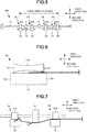
- Fig. 5 is a diagram illustrating the constitution of the sheet discharge roller 400 which may generate streaks on the image receiving medium.
- the constitution of the first roller pair 5A in the sheet discharge roller 400 is similar to that of the second roller pair 5B.
- Fig. 6 is an enlarged view illustrating the first roller pair 5A which may generate streaks on the image receiving medium.
- the outer peripheral surface of the driving roller 51A is a concave curved surface of which the central part is recessed. In the first direction, both ends 511 and 512 of the driving roller 51A are located between both ends 521 and 522 of the driven roller 52.
- the center part of the driving roller 51A contacts with the edge of the image receiving medium, and the end 511 of the driving roller 51A in the conveyance path center side contacts with the edge of the image receiving medium at the conveyance path center side.
- the outer peripheral surface of the driving roller 51A is a concave curved surface, a contact pressure at the end 511 of the driving roller 51A is larger than that at the center part.
- a force F1 is generated at the edge of the image receiving medium to pull the image receiving medium to the conveyance path center side.
- Fig. 7 is an enlarged view illustrating the first and the second roller pairs 5A and 5B of the sheet discharge roller 400 which may generate streaks on the image receiving medium.
- the image receiving medium is bent by the roller for correction 6 towards the driven roller 52 side in the second direction, and in this way, a force F2 is generated at the edge of the image receiving medium to pull the image receiving medium towards the conveyance path center side.
- a force F2 is generated at the edge of the image receiving medium to pull the image receiving medium towards the conveyance path center side.
- the edge of the image receiving medium is pulled towards the conveyance path center side from the first roller pair 5A, and there is a case in which streaks (creases) are generated on the image receiving medium.
- the end 511 of the driving roller 51A at the conveyance path center side protrudes towards the conveyance path center side with respect to the end 521 of the driven roller 52 at the conveyance path center side.
- the end 511 of the driving roller 51A at the conveyance path center side does not sandwich the edge of the image receiving medium with the driven roller 52.
- the present embodiment it is possible to suppress the generation of the force F1 for pulling the image receiving medium towards the conveyance path center side by the first roller pair 5A at the edge of the image receiving medium.
- the present embodiment as shown in Fig. 3 , only the force F2 by the roller for correction 6 is applied to the edge of the image receiving medium.
- the crease of the image receiving medium is not generated only with the force F2
- the damage to the image receiving medium at the time of discharging the sheet can be reduced.
- the roller for correction 6 rotates by receiving a drive force of a drive source in the same axis as the driving roller 51A, compared with a case of being located in the axis 72 of the driven roller 52, it is possible to act more strongly on the sheet and suppress the curl effectively.
- the present embodiment it is possible to suppress the curl in which the image receiving medium warps back in the conveying direction.
- the image receiving medium is a sheet
- moisture moves at a surface side contacting with the pressure roller 362 at low temperature.
- the evaporation amount of moisture at the surface side contacting with the pressure roller 362 of the image receiving medium is larger than that of moisture at the surface side contacting with the heat roller 361.
- the surface side contacting with the pressure roller 362 contracts and the conveyance path end side is easily curled toward the surface side contacting with the pressure roller 362.
- the roller for correction 6 presses the inner side (conveyance path center side) of the image receiving medium at the conveyance path end side toward the surface side contacting with the pressure roller 362, and thus, the curl can be suppressed effectively as compared with a case in which the inner side of the image receiving medium at the conveyance path end side is pressed towards the surface side contacting with the heat roller 361.
- the end 511 protrudes towards the conveyance path center side with respect to the end 521 of the driven roller 52.
- the occurrence of the streak can be suppressed at both edges of the image receiving medium with the predetermined size.
- the driving roller 51A is arranged to press the driven roller 52 to contact therewith, and the outer peripheral surface thereof becomes the concave curved surface.
- the end 512 as well as the center part of the driving roller 51A is also pressed to the driven roller 52 to contact therewith. Therefore, a sheet conveyance force of the first roller pair 5A in the present embodiment can be improved.
- both ends 513 and 514 of the driving roller 51B are positioned at the inner side of both ends 523 and 524 of the driven roller 52.
- both ends 523 and 524 as well as the center part are sufficiently pressed towards the driven roller 52 to contact therewith.
- the second roller pair 5B for conveying the conveyance path center side of the image receiving medium with the predetermined size, as a part where streaks are unlikely to occur is conveyed unlike the first roller pair 5A which conveys the conveyance path end side of the image receiving medium, the second roller pair 5B is constituted with emphasis on the conveyance force.
- the conveying roller 4 in the present embodiment can efficiently realize the conveyance force and the suppression of damage to the image receiving medium at the time of discharging the sheet.
- the first roller pair 5A may be located at positions corresponding to both ends of the image receiving medium with other sizes than A4 size in the first direction.
- the end 513 of the driving roller 51B at the conveyance path center side may protrude towards the conveyance path center side with respect to the end 523 of the driven roller 52 at the conveyance path center side.
- the roller for correction 6 may not be coaxial with the driving rollers 51A and 51B.
- the roller for correction 6 may be optional as long as it is located at the driven roller 52 side protruding towards the conveyance path center side or the driving rollers 51A and 51B side.
- the protrusion may not be a roller as in the present embodiment.
- the protrusion may be located at a position shifted from the driving rollers 51 A and 51B and the driven rollers 52 in the first direction.
- the protrusion is optional as long as it bends the sheet in an out-of-surface direction in order to suppress the curl due to heat of the sheet after the fixing processing.
- the protrusion may be coaxial with the driven roller 52 or may be on an axis on which there are no driving rollers 51A and 51B or the driven rollers 52.
- the protrusion may not be in the same position as the driving rollers 51A and 51B or the driven roller 52 in the sheet conveyance direction.
Landscapes
- Engineering & Computer Science (AREA)
- Mechanical Engineering (AREA)
- Physics & Mathematics (AREA)
- General Physics & Mathematics (AREA)
- Separation, Sorting, Adjustment, Or Bending Of Sheets To Be Conveyed (AREA)
- Handling Of Cut Paper (AREA)
- Paper Feeding For Electrophotography (AREA)
Abstract
a conveyance path configured to convey an image receiving medium;
a fixing device configured to fix an image formed on the image receiving medium;
a first roller arranged at the downstream side of a conveyance direction of the image receiving medium with respect to the fixing device, the first roller comprising an axis;
a second roller configured to face the first roller and an end thereof of which protrudes towards a central part of the conveyance path with respect to an end of the first roller at the central part of the conveyance path in a first direction substantially parallel to the axis; and
a protrusion arranged at the second roller side to protrude towards the first roller side from the second roller side and a protruding amount of which is greater than that of the second roller.
Description
- The present invention generally relates to the field of image forming technologies and embodiments described herein relate particularly to an image forming apparatus, a system comprising the corresponding and to reducing damage to an image receiving medium at the time of discharging a sheet.
- An image forming apparatus discharges an image receiving medium passing through a fixing device to a discharge tray via a sheet discharge roller (for example, Japanese Unexamined Patent Application Publication No.
2007-217187 - To solve such problems, there is provided an image forming apparatus, comprising:
- a conveyance path configured to convey an image receiving medium;
- a fixing device configured to fix an image formed on the image receiving medium;
- a first roller arranged at the downstream side of a conveyance direction of the image receiving medium with respect to the fixing device, the first roller comprising an axis;
- a second roller configured to face the first roller and an end thereof of which protrudes towards a central part of the conveyance path with respect to an end of the first roller at the central part of the conveyance path in a first direction substantially parallel to the axis; and
- a protrusion arranged at the second roller side to protrude towards the first roller side from the second roller side and a protruding amount of which is greater than that of the second roller.
- Preferably, the image forming apparatus further comprises:
- a drive source; wherein
- one of the first roller and the second roller comprises a driving roller driven by a drive force of the drive source, and
- an outer peripheral surface of the driving roller is a concave curved surface of which a center part is recessed in the first direction.
- Preferably still, the image forming apparatus further comprises a driven roller the outer peripheral surface of which is a flat surface in the first direction.
- Preferably yet, the image forming apparatus further comprises:
- a drive source; wherein
- the second roller is a driving roller driven by a drive force of the drive source, and
- the protrusion comprises a roller located on the same axis as the driving roller.
- Suitably, the other of the first roller and the second roller is a driven roller for rotating along with the sheet, and
- the driving roller is longer than the driven roller in the first direction.
- Suitably still, the image forming apparatus further comprises:
- a plurality of roller pairs arranged at intervals in the first direction, wherein
- the roller pairs comprise two first roller pairs corresponding to both ends of the image receiving medium with a predetermined size in the first direction and two second roller pairs between the two first roller pairs in the first direction,
- the first roller pair comprises the first roller and the second roller,
- the second roller pair comprises a third roller and a fourth roller facing the third roller and on the same axis as the second roller, and
- in the second roller pair, the fourth roller is shorter than the third roller in the first direction and both ends of the fourth roller in the first direction are located between both ends of the third roller.
- Suitably yet, the image forming apparatus further comprises:
- at least two roller pairs arranged at intervals in the first direction.
- Typically, the protrusion comprises a roller.
- Typically still, the protrusion is configured to bend the image receiving medium in an out-of-surface direction to suppress curling.
- Typically yet, the protrusion is positioned coaxial with the driven roller.
- Typically further, the protrusion is positioned so not to be coaxial with the driven roller.
- The invention also relates to an image forming system, comprising:
- a conveyance means configured to convey an image receiving medium;
- a fixing means configured to fix an image formed on the image receiving medium;
- a first roller means arranged at the downstream side of a conveyance direction of the image receiving medium with respect to the fixing means, the first roller means comprising an axis;
- a second roller means configured to face the first roller means and an end thereof of which protrudes towards a central part of the conveyance means with respect to an end of the first roller means at the central part of the conveyance means in a first direction substantially parallel to the axis; and
- a protrusion means arranged at the second roller side to protrude towards the first roller side from the second roller side and a protruding amount of which is greater than that of the second roller means.
- The invention further relates to a method of reducing curl after forming an image on an image receiving medium, comprising:
- forming the image on the image receiving medium using the image forming apparatus as defined above.
- The invention also concerns a method of reducing streaks after forming an image on an image receiving medium, comprising:
- forming the image on the image receiving medium using the image forming apparatus as defined above.
- Preferably, a contact pressure at an end of the driving roller with the image receiving medium is larger than a contact pressure at a center part of the driving roller with the image receiving medium.
- The above and other objects, features and advantages of the present invention will be made apparent from the following description of the preferred embodiments, given as non-limiting examples, with reference to the accompanying drawings, in which:
-
Fig. 1 is a diagram illustrating an image forming apparatus; -
Fig. 2 is a diagram illustrating the constitution of a sheet discharge roller; -
Fig. 3 is an enlarged view of a first and the second roller pairs at the left side inFig. 2 . -
Fig. 4 is an enlarged view of the first roller pair. -
Fig. 5 is a diagram illustrating the constitution of the sheet discharge roller which may generate streaks on the image receiving medium; -
Fig. 6 is an enlarged view illustrating the first roller pair which may generate streaks on the image receiving medium; and -
Fig. 7 is an enlarged view illustrating the first and the second roller pairs which may generate streaks on the image receiving medium. - Generally, in accordance with an embodiment, an image forming apparatus comprises a conveyance path, a fixing device, a first roller, an axis, a second roller and a protrusion. The conveyance path conveys an image receiving medium. The fixing device fixes an image formed on the image receiving medium. The first roller is arranged at the downstream side of a conveyance direction of the image receiving medium with respect to the fixing device. The axis is an axis of the first roller. The second roller faces the first roller and an end thereof protrudes towards a central part of the conveyance path with respect to an end of the first roller at the central part of the conveyance path in a first direction substantially parallel to the axis. The protrusion is arranged at the second roller side to protrude towards the first roller side from the second roller side and a protruding amount is greater than that of the second roller.
- The above embodiments can be applied mutatis mutandis to a system comprising the corresponding means.
-
Fig. 1 is a diagram illustrating animage forming apparatus 200. - The
image forming apparatus 200 reads a document on a document tray Rt by anautomatic document feeder 9 with a scanningoptical system 10. Theimage forming apparatus 200 has acassette 11. The image receiving medium is placed in thecassette 11. The image forming medium is a sheet, an envelope, an OHP image recording medium and the like. Theimage forming apparatus 200 picks up the image receiving medium from thecassette 11 with pickup rollers 31∼34 to convey the image receiving medium to aconveyance path 13. Theconveyance path 13 is a passage that extends from thecassette 11 side to adischarge tray 37 side to convey the image receiving medium. - Further, in the following description, since the image receiving medium is conveyed from the
cassette 11 to thedischarge tray 37, thecassette 11 side is set to an upstream side with respect to the conveyance direction of the image receiving medium, and thedischarge tray 37 side is set to a downstream side with respect to the conveyance direction. Theimage forming apparatus 200 conveys the image receiving medium picked up from thecassette 11 by the pickup rollers to a secondary transfer position U by a conveyance roller and a resist roller. - The
image forming apparatus 200 forms an electrostatic latent image onphotoconductive drums 2Y∼2K (2Y, 2M, 2C and 2K, and other reference numerals are the same) by a laser optical system 30 based on image data of the document. Theimage forming apparatus 200drives developing devices 3Y∼3K to develop the electrostatic latent images on thephotoconductive drums 2Y∼2K with toner of Y∼K to form toner images of Y∼K on thephotoconductive drums 2Y∼2K. - The
image forming apparatus 200 transfers the toner images of Y∼K on thephotoconductive drums 2Y∼2K onto atransfer belt 35 in the order of Y, M, C and K to form one color toner image on thetransfer belt 35. Theimage forming apparatus 200 transfers the toner image on thetransfer belt 35 onto the image receiving medium at the secondary transfer position U. - The
image forming apparatus 200 heats the image receiving medium at a fixingdevice 36. The fixingdevice 36 fixes the toner image on the image receiving medium. The fixingdevice 36 has a heat source. The fixingdevice 36 has aheat roller 361 which is heated by the heat source and apressure roller 362 which pressurizes theheat roller 361. Theheat roller 361 is arranged at thetransfer belt 35 side between two sides of theconveyance path 13 which face each other across the image receiving medium. Theheat roller 361 heats a surface side of the image receiving medium where the toner image is formed at the time of a simplex printing. The type of the heat source is not limited. The heat source may be constituted by a lamp heater such as a halogen lamp or a resistance heating body such as a thermal head. The heat source may also be an IH (induction heating) type heater. Theimage discharge apparatus 200 discharges the image receiving medium after a fixing processing by thesheet discharge roller 4 to thedischarge tray 37. -
Fig. 2 is a diagram illustrating the constitution of thesheet discharge roller 4. - The
sheet discharge roller 4 is a roller for conveying the image receiving medium to thedischarge tray 37. Thesheet discharge roller 4 is provided at the conveyance direction downstream side of the fixingdevice 36 and at the conveyance direction upstream side of thedischarge tray 37. - The
sheet discharge roller 4 is provided in the vicinity of thedischarge tray 37. The image receiving medium is discharged to thedischarge tray 37 by thesheet discharge roller 4. Thesheet discharge roller 4 has a plurality of roller pairs 5. Thesheet discharge roller 4 has a plurality of rollers for correction 6 (protrusion). Thesheet discharge roller 4 also has adrive axis 71 and anaxis 72 as the axes of theroller pair 5. Herein, an axial direction of the sheet discharge roller 4 (direction substantially parallel to the drive axis 71) is set to a first direction and a direction orthogonal to the first direction is set to a second direction. - The
sheet discharge roller 4 has the function of correcting the curl of the image receiving medium. If the image receiving medium passes through the fixingdevice 36, since the image receiving medium receives heat and pressure from the fixingdevice 36, the image receiving medium sometimes curls. If the image receiving medium is discharged to thedischarge tray 37 in a curled state, the loading property of the image receiving medium is impaired. Therefore, thesheet discharge roller 4 corrects the curl of the image receiving medium by bending the image receiving medium towards the second direction orthogonal to the axial direction of thesheet discharge roller 4. - The plurality of roller pairs 5 is positioned at intervals in the first direction orthogonal to the conveyance direction of the image receiving medium.
- A
first roller pair 5A includes a drivingroller 51A (second roller) and a driven roller 52 (first roller). Asecond roller pair 5B includes a drivingroller 51B (fourth roller) and a driven roller 52 (third roller). The drivingrollers transfer belt 35 and theheat roller 361 side between two sides of theconveyance path 13 which face each other across the image receiving medium. The drivingrollers rollers transfer belt 35 or theheat roller 361 between the two sides of theconveyance path 13 which face each other across the image receiving medium. - The driving
rollers drive axis 71 rotated by a drive source (not shown). The drivingrollers rollers rollers 52 and contact the drivenrollers 52 in the absence of the image receiving medium. The drivingroller 51A is longer than the drivingroller 51B in the first direction. - The first roller pairs 5A are provided at positions corresponding to both ends of the image receiving medium with a predetermined size (for example, A4 size sheet). The second roller pairs 5B are sandwiched between the first roller pairs 5A. Hereinafter, the
first roller pair 5A is described by taking a width of the A4 size as an example. - The driven
rollers 52 of the first and the second roller pairs 5A and 5B have the same constitution. The drivenrollers 52 are provided on theaxis 72. The drivenrollers 52 are rotatable and rotate along with the image receiving medium and the drivingrollers - The rollers for
correction 6 are arranged between the drivingrollers drive axis 71. -
Fig. 3 is an enlarged view of a first and the second roller pairs 5A and 5B at the left side inFig. 2 . Hereinafter, in the first direction, a center side of theconveyance path 13 is described as a conveyance path center side (right side inFig. 3 ), and an end side of theconveyance path 13 is described as a conveyance path end side (left side inFig. 3 ). - In the
first roller pair 5A, the drivingroller 51A is longer than the drivenroller 52 in the first direction. In the first direction, anend 511 of the drivingroller 51A at the conveyance path center side protrudes towards the conveyance path direction center side with respect to anend 521 of the drivenroller 52 at the conveyance path center side. In the first direction, anend 512 of the drivingroller 51A at the conveyance path end side protrudes to the conveyance path center side with respect to anend 522 of the drivenroller 52 at the conveyance path end side. - In the
second roller pair 5B, the drivingroller 51B is shorter than the drivenroller 52 in the first direction. In the first direction, both ends 513 and 514 of the drivingroller 51B are located between both ends 523 and 524 of the drivenroller 52. - The roller for
correction 6 has a larger diameter than the drivingrollers correction 6 protrudes from the drivingrollers roller 52 side, and a protrusion amount thereof is greater than that of the drivingrollers - At the
end 521 of the drivenroller 52, a point at the end at the drivingroller 51 A side in the second direction is set to P1, and a line drawn from P1 to the first direction is set to L1. In the roller forcorrection 6, a point located at the drivenroller 52 side in the second direction and also located at the end of the conveyance path end side is set to P2. A line for connecting the point P1 with P2 is set to L2. An angle θ formed by L1 and L2 is 4.6° or more. -
Fig. 4 is an enlarged view of thefirst roller pair 5A. - An outer peripheral surface of the driving
roller 51A is a concave curved surface of which the central part is recessed in the first direction. - An outer peripheral surface of the driven
roller 52 is flat in the first direction. - A distance D in the second direction between the central part of the outer peripheral surface of the driving
roller 51A in the first direction and the outer peripheral surface of the drivenroller 52 is set to, for example, 20∼30 microns. - Hereinafter, first, the constitution of a
sheet discharge roller 400 which may generate streaks on the image receiving medium and a function of thesheet discharge roller 400 on the image receiving medium are described. Next, the function of thesheet discharge roller 4 of the present embodiment on the image receiving medium is described. In the following description, each element of thesheet discharge roller 400 is donated with the same reference numeral as each element of the present embodiment. -
Fig. 5 is a diagram illustrating the constitution of thesheet discharge roller 400 which may generate streaks on the image receiving medium. - The constitution of the
first roller pair 5A in thesheet discharge roller 400 is similar to that of thesecond roller pair 5B. -
Fig. 6 is an enlarged view illustrating thefirst roller pair 5A which may generate streaks on the image receiving medium. - In the
first roller pair 5A, the outer peripheral surface of the drivingroller 51A is a concave curved surface of which the central part is recessed. In the first direction, both ends 511 and 512 of the drivingroller 51A are located between both ends 521 and 522 of the drivenroller 52. - In the
sheet discharge roller 400, in a case in which an edge of the image receiving medium is located at the center of thefirst roller pair 5A, the center part of the drivingroller 51A contacts with the edge of the image receiving medium, and theend 511 of the drivingroller 51A in the conveyance path center side contacts with the edge of the image receiving medium at the conveyance path center side. As the outer peripheral surface of the drivingroller 51A is a concave curved surface, a contact pressure at theend 511 of the drivingroller 51A is larger than that at the center part. Thus, a force F1 is generated at the edge of the image receiving medium to pull the image receiving medium to the conveyance path center side. -
Fig. 7 is an enlarged view illustrating the first and the second roller pairs 5A and 5B of thesheet discharge roller 400 which may generate streaks on the image receiving medium. - The image receiving medium is bent by the roller for
correction 6 towards the drivenroller 52 side in the second direction, and in this way, a force F2 is generated at the edge of the image receiving medium to pull the image receiving medium towards the conveyance path center side. In the constitution of thesheet discharge roller 400, by these forces F1 and F2, the edge of the image receiving medium is pulled towards the conveyance path center side from thefirst roller pair 5A, and there is a case in which streaks (creases) are generated on the image receiving medium. - Return to
Fig. 4 , in the present embodiment, theend 511 of the drivingroller 51A at the conveyance path center side protrudes towards the conveyance path center side with respect to theend 521 of the drivenroller 52 at the conveyance path center side. Thus, in the present embodiment, in a case in which the edge of the image receiving medium is positioned at the center of thefirst roller pair 5A, theend 511 of the drivingroller 51A at the conveyance path center side does not sandwich the edge of the image receiving medium with the drivenroller 52. - In this way, in the present embodiment, it is possible to suppress the generation of the force F1 for pulling the image receiving medium towards the conveyance path center side by the
first roller pair 5A at the edge of the image receiving medium. Thus, in the present embodiment, as shown inFig. 3 , only the force F2 by the roller forcorrection 6 is applied to the edge of the image receiving medium. As the crease of the image receiving medium is not generated only with the force F2, in the present embodiment, it is possible to suppress the generation of streaks on the image receiving medium due to thefirst roller pair 5A. Thus, in the present embodiment, the damage to the image receiving medium at the time of discharging the sheet can be reduced. - In the present embodiment, as the roller for
correction 6 rotates by receiving a drive force of a drive source in the same axis as the drivingroller 51A, compared with a case of being located in theaxis 72 of the drivenroller 52, it is possible to act more strongly on the sheet and suppress the curl effectively. - In the present embodiment, it is possible to suppress the curl in which the image receiving medium warps back in the conveying direction. For example, in a case in which the image receiving medium is a sheet, at the time of fixing, in the image receiving medium, moisture moves at a surface side contacting with the
pressure roller 362 at low temperature. Thus, the evaporation amount of moisture at the surface side contacting with thepressure roller 362 of the image receiving medium is larger than that of moisture at the surface side contacting with theheat roller 361. Thus, in the image receiving medium, the surface side contacting with thepressure roller 362 contracts and the conveyance path end side is easily curled toward the surface side contacting with thepressure roller 362. In the present embodiment, the roller forcorrection 6 presses the inner side (conveyance path center side) of the image receiving medium at the conveyance path end side toward the surface side contacting with thepressure roller 362, and thus, the curl can be suppressed effectively as compared with a case in which the inner side of the image receiving medium at the conveyance path end side is pressed towards the surface side contacting with theheat roller 361. - In the present embodiment, in the first roller pairs 5A corresponding to both ends of the image receiving medium with the predetermined size (for example, A4 size sheet), the
end 511 protrudes towards the conveyance path center side with respect to theend 521 of the drivenroller 52. Thus, the occurrence of the streak can be suppressed at both edges of the image receiving medium with the predetermined size. - In the
first roller pair 5A for conveying the conveyance path end side of the image receiving medium with the predetermined size, the drivingroller 51A is arranged to press the drivenroller 52 to contact therewith, and the outer peripheral surface thereof becomes the concave curved surface. Thus, theend 512 as well as the center part of the drivingroller 51A is also pressed to the drivenroller 52 to contact therewith. Therefore, a sheet conveyance force of thefirst roller pair 5A in the present embodiment can be improved. - In the
second roller pair 5B for conveying the conveyance path center side of the image receiving medium with the predetermined size, both ends 513 and 514 of the drivingroller 51B are positioned at the inner side of both ends 523 and 524 of the drivenroller 52. As the outer peripheral surface of the drivingroller 51B becomes the concave curved surface, both ends 523 and 524 as well as the center part are sufficiently pressed towards the drivenroller 52 to contact therewith. In this way, in thesecond roller pair 5B for conveying the conveyance path center side of the image receiving medium with the predetermined size, as a part where streaks are unlikely to occur is conveyed unlike thefirst roller pair 5A which conveys the conveyance path end side of the image receiving medium, thesecond roller pair 5B is constituted with emphasis on the conveyance force. Thus, the conveyingroller 4 in the present embodiment can efficiently realize the conveyance force and the suppression of damage to the image receiving medium at the time of discharging the sheet. - The
first roller pair 5A may be located at positions corresponding to both ends of the image receiving medium with other sizes than A4 size in the first direction. - Even in the
second roller pair 5B, theend 513 of the drivingroller 51B at the conveyance path center side may protrude towards the conveyance path center side with respect to theend 523 of the drivenroller 52 at the conveyance path center side. - The roller for
correction 6 may not be coaxial with the drivingrollers correction 6 may be optional as long as it is located at the drivenroller 52 side protruding towards the conveyance path center side or the drivingrollers - The protrusion may not be a roller as in the present embodiment. The protrusion may be located at a position shifted from the driving
rollers rollers 52 in the first direction. The protrusion is optional as long as it bends the sheet in an out-of-surface direction in order to suppress the curl due to heat of the sheet after the fixing processing. The protrusion may be coaxial with the drivenroller 52 or may be on an axis on which there are no drivingrollers rollers 52. The protrusion may not be in the same position as the drivingrollers roller 52 in the sheet conveyance direction.
Claims (15)
- An image forming apparatus, comprising:a conveyance path configured to convey an image receiving medium;a fixing device configured to fix an image formed on the image receiving medium;a first roller arranged at the downstream side of a conveyance direction of the image receiving medium with respect to the fixing device, the first roller comprising an axis;a second roller configured to face the first roller and an end thereof of which protrudes towards a central part of the conveyance path with respect to an end of the first roller at the central part of the conveyance path in a first direction substantially parallel to the axis; anda protrusion arranged at the second roller side to protrude towards the first roller side from the second roller side and a protruding amount of which is greater than that of the second roller.
- The image forming apparatus according to claim 1, further comprising:a drive source; whereinone of the first roller and the second roller comprises a driving roller driven by a drive force of the drive source, andan outer peripheral surface of the driving roller is a concave curved surface of which a center part is recessed in the first direction.
- The image forming apparatus according to claim 1 or 2, further comprising a driven roller the outer peripheral surface of which is a flat surface in the first direction.
- The image forming apparatus according to any one of claims 1 to 3, further comprising:a drive source; whereinthe second roller is a driving roller driven by a drive force of the drive source, andthe protrusion comprises a roller located on the same axis as the driving roller.
- The image forming apparatus according to any one of claims 2 to 4, wherein
the other of the first roller and the second roller is a driven roller for rotating along with the sheet, and
the driving roller is longer than the driven roller in the first direction. - The image forming apparatus according to any one of claims 1 to 5, further comprising:a plurality of roller pairs arranged at intervals in the first direction, whereinthe roller pairs comprise two first roller pairs corresponding to both ends of the image receiving medium with a predetermined size in the first direction and two second roller pairs between the two first roller pairs in the first direction,the first roller pair comprises the first roller and the second roller,the second roller pair comprises a third roller and a fourth roller facing the third roller and on the same axis as the second roller, andin the second roller pair, the fourth roller is shorter than the third roller in the first direction and both ends of the fourth roller in the first direction are located between both ends of the third roller.
- The image forming apparatus according to any one of claims 1 to 6, further comprising:at least two roller pairs arranged at intervals in the first direction.
- The image forming apparatus according to any one of claims 1 to 7, wherein
the protrusion comprises a roller. - The image forming apparatus according to any one of claims 1 to 8, wherein
the protrusion is configured to bend the image receiving medium in an out-of-surface direction to suppress curling. - The image forming apparatus according to any one of claims 2 to 9, wherein
the protrusion is positioned coaxial with the driven roller. - The image forming apparatus according to any one of claims 2 to 9, wherein
the protrusion is positioned so not to be coaxial with the driven roller. - An image forming system, comprising:a conveyance means configured to convey an image receiving medium;a fixing means configured to fix an image formed on the image receiving medium;a first roller means arranged at the downstream side of a conveyance direction of the image receiving medium with respect to the fixing means, the first roller means comprising an axis;a second roller means configured to face the first roller means and an end thereof of which protrudes towards a central part of the conveyance means with respect to an end of the first roller means at the central part of the conveyance means in a first direction substantially parallel to the axis; anda protrusion means arranged at the second roller side to protrude towards the first roller side from the second roller side and a protruding amount of which is greater than that of the second roller means.
- A method of reducing curl after forming an image on an image receiving medium, comprising:forming the image on the image receiving medium using the image forming apparatus according to claim 1.
- A method of reducing streaks after forming an image on an image receiving medium, comprising:forming the image on the image receiving medium using the image forming apparatus according to claim 2.
- The method of reducing streaks according to claim 14, wherein
a contact pressure at an end of the driving roller with the image receiving medium is larger than a contact pressure at a center part of the driving roller with the image receiving medium.
Applications Claiming Priority (1)
| Application Number | Priority Date | Filing Date | Title |
|---|---|---|---|
| JP2016108326A JP2017215420A (en) | 2016-05-31 | 2016-05-31 | Image forming apparatus |
Publications (1)
| Publication Number | Publication Date |
|---|---|
| EP3251991A1 true EP3251991A1 (en) | 2017-12-06 |
Family
ID=58387674
Family Applications (1)
| Application Number | Title | Priority Date | Filing Date |
|---|---|---|---|
| EP17161471.2A Withdrawn EP3251991A1 (en) | 2016-05-31 | 2017-03-17 | Image forming apparatus |
Country Status (3)
| Country | Link |
|---|---|
| US (1) | US20170343934A1 (en) |
| EP (1) | EP3251991A1 (en) |
| JP (1) | JP2017215420A (en) |
Families Citing this family (1)
| Publication number | Priority date | Publication date | Assignee | Title |
|---|---|---|---|---|
| JP7268391B2 (en) * | 2019-02-20 | 2023-05-08 | セイコーエプソン株式会社 | Conveyor and recording device |
Citations (6)
| Publication number | Priority date | Publication date | Assignee | Title |
|---|---|---|---|---|
| JP2000351512A (en) * | 1999-06-14 | 2000-12-19 | Seiko Epson Corp | Paper ejection device |
| JP2001106412A (en) * | 1999-10-06 | 2001-04-17 | Fuji Xerox Co Ltd | Paper discharging device |
| JP2002003052A (en) * | 2000-06-23 | 2002-01-09 | Canon Inc | Image forming device |
| JP2007217187A (en) | 2006-01-17 | 2007-08-30 | Ricoh Co Ltd | Image forming apparatus |
| US20090243212A1 (en) * | 2008-03-31 | 2009-10-01 | Canon Kabushiki Kaisha | Sheet conveying apparatus and image forming apparatus |
| EP2374744A1 (en) * | 2010-04-07 | 2011-10-12 | Ricoh Company, Ltd. | Sheet conveying device, sheet post-processing apparatus, and image forming apparatus |
Family Cites Families (4)
| Publication number | Priority date | Publication date | Assignee | Title |
|---|---|---|---|---|
| US5153663A (en) * | 1991-05-31 | 1992-10-06 | Xerox Corporation | Printing apparatus employing a compliant sheet corrugating device |
| US6190070B1 (en) * | 1998-10-13 | 2001-02-20 | Xerox Corporation | Printer with media corrugation at media output |
| JP4846651B2 (en) * | 2007-05-01 | 2011-12-28 | 株式会社リコー | Paper discharge device and image forming apparatus |
| US7992863B2 (en) * | 2009-04-01 | 2011-08-09 | Xerox Corporation | Apparatus and method for temporarily increasing the beam strength of a media sheet in a printer |
-
2016
- 2016-05-31 JP JP2016108326A patent/JP2017215420A/en active Pending
-
2017
- 2017-02-22 US US15/438,984 patent/US20170343934A1/en not_active Abandoned
- 2017-03-17 EP EP17161471.2A patent/EP3251991A1/en not_active Withdrawn
Patent Citations (6)
| Publication number | Priority date | Publication date | Assignee | Title |
|---|---|---|---|---|
| JP2000351512A (en) * | 1999-06-14 | 2000-12-19 | Seiko Epson Corp | Paper ejection device |
| JP2001106412A (en) * | 1999-10-06 | 2001-04-17 | Fuji Xerox Co Ltd | Paper discharging device |
| JP2002003052A (en) * | 2000-06-23 | 2002-01-09 | Canon Inc | Image forming device |
| JP2007217187A (en) | 2006-01-17 | 2007-08-30 | Ricoh Co Ltd | Image forming apparatus |
| US20090243212A1 (en) * | 2008-03-31 | 2009-10-01 | Canon Kabushiki Kaisha | Sheet conveying apparatus and image forming apparatus |
| EP2374744A1 (en) * | 2010-04-07 | 2011-10-12 | Ricoh Company, Ltd. | Sheet conveying device, sheet post-processing apparatus, and image forming apparatus |
Also Published As
| Publication number | Publication date |
|---|---|
| US20170343934A1 (en) | 2017-11-30 |
| JP2017215420A (en) | 2017-12-07 |
Similar Documents
| Publication | Publication Date | Title |
|---|---|---|
| US11447350B2 (en) | Sheet conveyance apparatus | |
| US11199801B2 (en) | Sheet discharging apparatus having electrostatic charge removal and image forming apparatus | |
| US20150097333A1 (en) | Image forming system, image forming apparatus, sheet feed apparatus, and image forming method | |
| CN104656396B (en) | Image processing system | |
| CN104252113B (en) | Medium outlet tube and image forming apparatus | |
| US9751708B2 (en) | Sheet transport device and image forming apparatus | |
| US10882708B2 (en) | Sheet conveyance device, image forming apparatus, method, and storage medium | |
| US20170343934A1 (en) | Image forming apparatus | |
| JP2000095411A (en) | Sheet conveying device and image forming device | |
| US20100329718A1 (en) | Image forming apparatus | |
| JP2001048399A (en) | Image forming device | |
| US20190092594A1 (en) | Sheet conveying apparatus and image forming apparatus | |
| JP5962557B2 (en) | Image forming system | |
| JP6727969B2 (en) | Image forming device | |
| JP2016060606A (en) | Image forming apparatus | |
| US11613440B2 (en) | Sheet conveyance device and image forming apparatus | |
| JP4534746B2 (en) | Paper curl correction device, image forming device | |
| US20190086857A1 (en) | Image forming apparatus and image forming method | |
| US9090420B2 (en) | Image forming system and relay apparatus | |
| JP5004862B2 (en) | Curl correction device and image forming apparatus | |
| JP2014163998A (en) | Fixing apparatus and image forming apparatus | |
| JP2017114636A (en) | Sheet curl correction device and image formation apparatus having the same | |
| JP3815533B2 (en) | Image forming apparatus | |
| JP2002287554A (en) | Fixing device | |
| JP2002293449A (en) | Guide, fixing device, and image forming device |
Legal Events
| Date | Code | Title | Description |
|---|---|---|---|
| PUAI | Public reference made under article 153(3) epc to a published international application that has entered the european phase |
Free format text: ORIGINAL CODE: 0009012 |
|
| AK | Designated contracting states |
Kind code of ref document: A1 Designated state(s): AL AT BE BG CH CY CZ DE DK EE ES FI FR GB GR HR HU IE IS IT LI LT LU LV MC MK MT NL NO PL PT RO RS SE SI SK SM TR |
|
| AX | Request for extension of the european patent |
Extension state: BA ME |
|
| 17P | Request for examination filed |
Effective date: 20180606 |
|
| RBV | Designated contracting states (corrected) |
Designated state(s): AL AT BE BG CH CY CZ DE DK EE ES FI FR GB GR HR HU IE IS IT LI LT LU LV MC MK MT NL NO PL PT RO RS SE SI SK SM TR |
|
| STAA | Information on the status of an ep patent application or granted ep patent |
Free format text: STATUS: THE APPLICATION HAS BEEN WITHDRAWN |
|
| 18W | Application withdrawn |
Effective date: 20190307 |