EP3251792A2 - A vibropeening system and a method of using the same - Google Patents
A vibropeening system and a method of using the same Download PDFInfo
- Publication number
- EP3251792A2 EP3251792A2 EP17173804.0A EP17173804A EP3251792A2 EP 3251792 A2 EP3251792 A2 EP 3251792A2 EP 17173804 A EP17173804 A EP 17173804A EP 3251792 A2 EP3251792 A2 EP 3251792A2
- Authority
- EP
- European Patent Office
- Prior art keywords
- enclosure
- vibropeening
- article
- main frame
- bed
- Prior art date
- Legal status (The legal status is an assumption and is not a legal conclusion. Google has not performed a legal analysis and makes no representation as to the accuracy of the status listed.)
- Withdrawn
Links
Images


Classifications
-
- B—PERFORMING OPERATIONS; TRANSPORTING
- B23—MACHINE TOOLS; METAL-WORKING NOT OTHERWISE PROVIDED FOR
- B23P—METAL-WORKING NOT OTHERWISE PROVIDED FOR; COMBINED OPERATIONS; UNIVERSAL MACHINE TOOLS
- B23P9/00—Treating or finishing surfaces mechanically, with or without calibrating, primarily to resist wear or impact, e.g. smoothing or roughening turbine blades or bearings; Features of such surfaces not otherwise provided for, their treatment being unspecified
-
- B—PERFORMING OPERATIONS; TRANSPORTING
- B24—GRINDING; POLISHING
- B24B—MACHINES, DEVICES, OR PROCESSES FOR GRINDING OR POLISHING; DRESSING OR CONDITIONING OF ABRADING SURFACES; FEEDING OF GRINDING, POLISHING, OR LAPPING AGENTS
- B24B19/00—Single-purpose machines or devices for particular grinding operations not covered by any other main group
- B24B19/14—Single-purpose machines or devices for particular grinding operations not covered by any other main group for grinding turbine blades, propeller blades or the like
-
- B—PERFORMING OPERATIONS; TRANSPORTING
- B21—MECHANICAL METAL-WORKING WITHOUT ESSENTIALLY REMOVING MATERIAL; PUNCHING METAL
- B21D—WORKING OR PROCESSING OF SHEET METAL OR METAL TUBES, RODS OR PROFILES WITHOUT ESSENTIALLY REMOVING MATERIAL; PUNCHING METAL
- B21D31/00—Other methods for working sheet metal, metal tubes, metal profiles
- B21D31/06—Deforming sheet metal, tubes or profiles by sequential impacts, e.g. hammering, beating, peen forming
-
- B—PERFORMING OPERATIONS; TRANSPORTING
- B23—MACHINE TOOLS; METAL-WORKING NOT OTHERWISE PROVIDED FOR
- B23P—METAL-WORKING NOT OTHERWISE PROVIDED FOR; COMBINED OPERATIONS; UNIVERSAL MACHINE TOOLS
- B23P15/00—Making specific metal objects by operations not covered by a single other subclass or a group in this subclass
- B23P15/02—Making specific metal objects by operations not covered by a single other subclass or a group in this subclass turbine or like blades from one piece
-
- B—PERFORMING OPERATIONS; TRANSPORTING
- B24—GRINDING; POLISHING
- B24B—MACHINES, DEVICES, OR PROCESSES FOR GRINDING OR POLISHING; DRESSING OR CONDITIONING OF ABRADING SURFACES; FEEDING OF GRINDING, POLISHING, OR LAPPING AGENTS
- B24B31/00—Machines or devices designed for polishing or abrading surfaces on work by means of tumbling apparatus or other apparatus in which the work and/or the abrasive material is loose; Accessories therefor
- B24B31/003—Machines or devices designed for polishing or abrading surfaces on work by means of tumbling apparatus or other apparatus in which the work and/or the abrasive material is loose; Accessories therefor whereby the workpieces are mounted on a holder and are immersed in the abrasive material
-
- B—PERFORMING OPERATIONS; TRANSPORTING
- B24—GRINDING; POLISHING
- B24B—MACHINES, DEVICES, OR PROCESSES FOR GRINDING OR POLISHING; DRESSING OR CONDITIONING OF ABRADING SURFACES; FEEDING OF GRINDING, POLISHING, OR LAPPING AGENTS
- B24B31/00—Machines or devices designed for polishing or abrading surfaces on work by means of tumbling apparatus or other apparatus in which the work and/or the abrasive material is loose; Accessories therefor
- B24B31/06—Machines or devices designed for polishing or abrading surfaces on work by means of tumbling apparatus or other apparatus in which the work and/or the abrasive material is loose; Accessories therefor involving oscillating or vibrating containers
- B24B31/062—Machines or devices designed for polishing or abrading surfaces on work by means of tumbling apparatus or other apparatus in which the work and/or the abrasive material is loose; Accessories therefor involving oscillating or vibrating containers the workpieces travelling through the containers
-
- C—CHEMISTRY; METALLURGY
- C21—METALLURGY OF IRON
- C21D—MODIFYING THE PHYSICAL STRUCTURE OF FERROUS METALS; GENERAL DEVICES FOR HEAT TREATMENT OF FERROUS OR NON-FERROUS METALS OR ALLOYS; MAKING METAL MALLEABLE, e.g. BY DECARBURISATION OR TEMPERING
- C21D7/00—Modifying the physical properties of iron or steel by deformation
- C21D7/02—Modifying the physical properties of iron or steel by deformation by cold working
- C21D7/04—Modifying the physical properties of iron or steel by deformation by cold working of the surface
- C21D7/06—Modifying the physical properties of iron or steel by deformation by cold working of the surface by shot-peening or the like
Definitions
- the present disclosure relates to a method and apparatus for vibropeening metallic components and particularly, but not exclusively, to a method and apparatus for vibropeening metallic components for a gas turbine engine.
- Shot peening involves directing a stream of steel, ceramic or glass peening media at the surface of the article.
- the impact of the peening media on the surface introduces compressive residual stresses into the surface layer of the article. These compressive residual stresses improve the high cycle fatigue strength of the article.
- Vibrofinishing involves immersing the article in a container together with a polishing mixture.
- the polishing mixture is typically made from polishing chips (usually plastic or ceramic), an abrasive paste and water. Vibration of the container causes the polishing mixture to flow around the article, resulting in removal of material from the surface of the article.
- the vibrofinishing process typically employed to reduce the surface roughness of an article, for example to improve aerodynamic performance of a turbine or compressor blade.
- Shot peening and vibrofinishing processes are often applied to the same article in sequence. This can be time consuming.
- Vibropeening is a surface finishing technique that combines the improvement in residual compressive stress provided by shot peening, with the reduction in surface roughness provided by vibrofinishing. This combination makes the vibropeening process quicker and more cost effective than the prior art combination of shot peening and vibrofinishing.
- the article to be processed is immersed in a trough, which is filled up with a stainless steel media, and vibrational energy is provided to the trough. Additionally, the article may be rotated within the trough to further increase the level of interaction between the media and the surface of the article.
- FIG. 1 illustrates a typical vibropeening apparatus 10 according to the prior art.
- the vibropeening apparatus 10 comprises a housing 20 within which is located a mounting frame 30 having a motor drive 40.
- the housing 20 accommodates a vibropeening bed 50 with the article 60 to be vibropeened being attached to the mounting frame 30 and suspended within the vibropeening bed 50.
- the motor drive 40 rotates the article 60 within the vibropeening bed 50.
- the vibropeening process may result in the component having low peening intensity, irregular peening treatment across the surface of the article, and, in worst cases, high distortion.
- a vibropeening apparatus comprising:
- the enclosure is accommodated within the main frame.
- the internal volume of the enclosure is less than the corresponding volume of the main frame. This makes the volume of the vibropeening bed accommodated within the enclosure smaller than the volume of a vibropeening bed accommodated within the main frame. This makes the vibropeening apparatus of the present invention more cost effective than the prior art equivalent.
- a predetermined clearance is defined between the article and the enclosure.
- the vibropeening bed By providing a predetermined clearance between the article and the enclosure, the vibropeening bed will provide a vibropeening effect uniformly over the entire surface of the article. This makes the apparatus of the present invention more efficient than the prior art equivalent.
- the predetermined clearance between the article and the enclosure reduces the volume of the vibropeening bed over the prior art equivalent in which the vibropeening bed fills the main frame. This reduces the cost of the vibropeening apparatus because there is less vibropeening media.
- the predetermined clearance between the article and the enclosure reduces the energy consumption of the vibropeening apparatus because there is a smaller distance over which the vibratory excitation energy can be dissipated, i.e. the smaller distance between the article and the enclosure. This makes the apparatus of the present invention more efficient than the prior art and therefore more convenient for a user.
- the vibropeening bed comprises a plurality of media particles, the media particles having a mean media particle size.
- the media particles will comprise spherical stainless steel particles with a mean media particle size of 5mm.
- the mean media particle size is the diameter of the spherical particles.
- the media particles may take an alternative geometry such as, for example, ovoid or cylindrical.
- the mean media particle size is a dimension that is characteristic of the particle geometry.
- the mean media particle size may be the cylindrical length.
- the predetermined clearance is approximately between five (5) and ten (10) times the mean media particle size.
- the mean media particle size is 5mm
- the predetermined clearance between the article and the casing is 40mm, which makes the predetermined clearance eight (8) times the mean media particle size.
- the predetermined clearance may be between five and ten times the mean media particle size.
- the enclosure is removably mounted within the main frame.
- the enclosure can readily be prepared outwith the vibropeening apparatus and simply installed in main frame when required for use. This makes the vibropeening apparatus of the present invention more convenient for a user than the prior art equivalent.
- the enclosure comprises a feed aperture, the feed aperture allowing for the ingress and egress of media particles.
- the feed aperture provides a user with the facility to load the enclosure with the vibropeening media particles . This makes the vibropeening apparatus of the present invention more convenient for a user than the prior art equivalent.
- the enclosure comprises an inner surface, the inner surface being formed from a thermoplastic polymeric material.
- the vibropeening bed is enclosed by a surface formed from a rubber material.
- This rubber material absorbs some of the vibratory energy provided to the vibropeening bed, which reduces the energy efficiency of such prior art arrangements.
- the enclosure further comprises a first end and an opposite second end, and an axis of rotation extending between the first end and the second end, and the article is removably secured to an internal surface of the first end of the enclosure.
- the article is secured to an internal surface of one of the axial internal ends of the enclosure. In this way, the article extends axially into the enclosure, and is rotated about this axis.
- the orientation of the article within the enclosure may be chosen on the basis of the geometry of the article itself.
- an article having an elongate geometry may be secured to the enclosure with the elongate axis aligned with the axis of rotation of the enclosure. This enables the vibropeening apparatus of the present invention to readily accommodate articles having elongate geometries.
- the enclosure further comprises a window allowing a visual inspection of the vibropeening bed.
- the window in the enclosure enables a user to visualise the media flow within the enclosure. This provides a measure of diagnostic capability to the user in the event of the vibropeening bed not operating correctly, which makes the apparatus of the present invention more convenient to a user than the prior art equivalent.
- the rotary motion is a unidirectional rotary motion.
- the rotary motion is an oscillatory rotary motion.
- Providing the enclosure with oscillatory rotary motion may enable the vibropeening of articles having a convoluted geometry to be completed more quickly than with a unidirectional rotary motion.
- a vibropeening apparatus comprising a main frame, an enclosure receivable within the main frame, and a rotary drive mechanism configured to rotate the enclosure, the method comprising the steps of:
- the enclosure is accommodated within the main frame.
- the internal volume of the enclosure is less than the corresponding volume of the main frame. This makes the volume of the vibropeening bed accommodated within the enclosure, smaller than the volume of a vibropeening bed accommodated within the main frame. This makes the vibropeening apparatus of the present invention more cost effective than that of the prior art equivalent.
- the step of positioning an article to be vibropeened within the enclosure comprises the step of:
- the vibropeening bed By providing a predetermined clearance between the article and the enclosure, the vibropeening bed will provide a vibropeening effect uniformly over the entire surface of the article. This makes the apparatus of the present invention more efficient than the prior art equivalent.
- the predetermined clearance between the article and the enclosure reduces the volume of the vibropeening bed over the prior art equivalent in which the vibropeening bed fills the main frame. This reduces the cost of the vibropeening apparatus because there is less vibropeening media.
- the predetermined clearance between the article and the enclosure reduces the energy consumption of the vibropeening apparatus because there is a smaller distance over which the vibratory excitation energy can be dissipated, i.e. the smaller distance between the article and the enclosure. This makes the apparatus of the present invention more efficient than the prior art and therefore more convenient for a user.
- the step of positioning an article to be vibropeened within the enclosure comprises the additional following step of:
- the article is secured to an internal surface of one of the axial internal ends of the enclosure. In this way, the article extends axially into the enclosure, and is rotated about this axis.
- the orientation of the article within the enclosure may be chosen on the basis of the geometry of the article itself.
- an article having an elongate geometry may be secured to the enclosure with the elongate axis aligned with the axis of rotation of the enclosure. This enables the vibropeening apparatus of the present invention to readily accommodate articles having elongate geometries.
- the step of rotating the enclosure comprises the step of:
- the step of rotating the enclosure comprises the step of:
- Providing the enclosure with oscillatory rotary motion may enable the vibropeening of articles having a convoluted or asymmetric geometry to be completed more quickly than with a unidirectional rotary motion.
- aspects of the disclosure provide devices, methods and systems which include and/or implement some or all of the actions described herein.
- the illustrative aspects of the disclosure are designed to solve one or more of the problems herein described and/or one or more other problems not discussed.
- a vibropeening apparatus according to an embodiment of the disclosure is designated generally by the reference numeral 100.
- the vibropeening apparatus 100 has a main frame 110, an enclosure 120 receivable within the main frame 110, a rotary drive mechanism 170 and an article 180 to be vibropeened.
- the article 180 is a fan blade for a turbofan gas turbine engine.
- the main frame 110 takes the form of a rectangular enclosure.
- the main frame 110 is formed as a steel fabrication.
- the main frame 110 may be formed from another metal, such as an aluminium alloy, or from a composite material, such as carbon fibre reinforced composite.
- the enclosure 120 is positioned within the main frame 110 such that it is fully enclosed by the main frame 110, but has sufficient clearance around it that it is able to be rotated around an axis of rotation 125 of the enclosure 120.
- the enclosure 120 is arranged to be removable from the main frame 110.
- the enclosure 120 may be mounted as an integral part of the main frame.
- the enclosure 120 has a first end 122 and an opposite second end 124.
- the enclosure 120 has an axis of rotation 125 that extends between the first end 122 and the second end 124.
- the enclosure 120 rotates about the axis of rotation 125 when the enclosure 120 is mounted within the main frame 110.
- the rotary drive mechanism 170 is arranged to provide rotary motion to the enclosure 120 within the main frame 110.
- the rotary drive mechanism 170 comprises an electric motor 172 having a driving portion 174.
- the driving portion 174 is connected via a transmission belt 176 to the driven portion 178.
- the driven portion 178 is connected to the enclosure 120 at the first end 122 of the enclosure 120.
- the rotary drive mechanism 170 may comprise any suitable source of rotary motion such as, for example, direct electric drive of the enclosure 120, hydraulic motor drive, hydrostatic motor drive, etc.
- the enclosure 120 comprises a first enclosure half 130 and a cooperating second enclosure half 132.
- a first enclosure half 130 Within the first enclosure half 130 is located a first enclosure lining half 134.
- a second enclosure lining half 136 Within the second enclosure half 132 is located a second enclosure lining half 136.
- Each of the first enclosure half 132 and the second enclosure half 134 is formed from a polymeric material.
- the first enclosure half 132 and the second enclosure half 134 may be formed from an alternative material such as, for example, a sheet metal or a fibre reinforced composite material.
- Each of the first enclosure lining half 134 and the second enclosure lining half 136 is formed from a polyurethane material.
- the first enclosure lining half 134 and the second enclosure lining half 136 may be formed from another thermoplastic material.
- This internal volume 126 has the same geometry as the article 180 to be vibropeened.
- the internal volume 126 is sized such that when the article 180 to be vibropeened is positioned in the internal volume 126, a predetermined clearance 128 is defined between the article 180 and the enclosure 120. This predetermined clearance 128 is defined over the entire extent of the article 180.
- the article 180 to be vibropeened is attached to the first end 122 of the enclosure 120.
- the internal volume 126 accommodates a vibropeening bed 160 within which is also located the article 180 to be vibropeened.
- the vibropeening bed 160 comprises a plurality of media particles 162.
- the media particles 162 are stainless steel balls having a mean media particle size 164, in this case a diameter, of 5mm.
- the media particles 164 may take the form of a vibropeening media having alternative particle geometry.
- the media particles may be spherical with a diameter larger or smaller than 5mm.
- the media particle geometry may be cubic, oblate spheroid, pyramidal, or a mixture thereof.
- the enclosure 120 comprises a feed aperture 138 in an external surface.
- the feed aperture 138 allows for the ingress and egress of media particles 162 from the internal volume 126.
- the enclosure 120 further comprises a window 140 in an external surface.
- the window 140 allows a user to visually inspect the vibropeening bed 160 located in the internal volume 126.
- the article 180 to be vibropeened is attached to the first end 122 of the enclosure 120.
- the first enclosure lining half 134 and the first enclosure half 130 are assembled over one side of the article 180.
- the second enclosure lining half 136 and the second enclosure half 132 are assembled over the opposite side of the article 180.
- the assembled enclosure 120 defines an internal volume 126 between the first enclosure lining half 134 and the second enclosure lining half 136, with the article 180 being positioned centrally within the internal volume 126.
- the vibropeening media particles 162 may then be poured into the internal volume 126 through the feed aperture 138.
- the rotary drive mechanism 170 provides rotary motion to the enclosure 120.
- this rotary motion is a unidirectional rotary motion.
- the enclosure 120 always rotates in the same rotational direction.
- the rotary motion is approximately 1 to 2 rpm.
- the rotary drive mechanism 170 provides an oscillatory rotary motion to the enclosure 110.
- the vibropeening media particles 162 may be drained from the internal volume 126 within the enclosure 120 via the feed aperture 138. The enclosure 120 may then be removed from the main frame 110.
- Disassembly of the enclosure 110 is the reverse of the assembly process described above.
Landscapes
- Engineering & Computer Science (AREA)
- Mechanical Engineering (AREA)
- Chemical & Material Sciences (AREA)
- Crystallography & Structural Chemistry (AREA)
- Materials Engineering (AREA)
- Metallurgy (AREA)
- Organic Chemistry (AREA)
- Structures Of Non-Positive Displacement Pumps (AREA)
- Finish Polishing, Edge Sharpening, And Grinding By Specific Grinding Devices (AREA)
- Percussion Or Vibration Massage (AREA)
Abstract
Description
- The present disclosure relates to a method and apparatus for vibropeening metallic components and particularly, but not exclusively, to a method and apparatus for vibropeening metallic components for a gas turbine engine.
- It is well known to employ surface finishing techniques to improve the surface finish and fatigue cycle life of metallic articles. Examples of such surface finishing techniques include shot peening and vibrofinishing.
- Shot peening involves directing a stream of steel, ceramic or glass peening media at the surface of the article. The impact of the peening media on the surface introduces compressive residual stresses into the surface layer of the article. These compressive residual stresses improve the high cycle fatigue strength of the article.
- Vibrofinishing, on the other hand, involves immersing the article in a container together with a polishing mixture. The polishing mixture is typically made from polishing chips (usually plastic or ceramic), an abrasive paste and water. Vibration of the container causes the polishing mixture to flow around the article, resulting in removal of material from the surface of the article. The vibrofinishing process typically employed to reduce the surface roughness of an article, for example to improve aerodynamic performance of a turbine or compressor blade.
- Shot peening and vibrofinishing processes are often applied to the same article in sequence. This can be time consuming.
- Vibropeening is a surface finishing technique that combines the improvement in residual compressive stress provided by shot peening, with the reduction in surface roughness provided by vibrofinishing. This combination makes the vibropeening process quicker and more cost effective than the prior art combination of shot peening and vibrofinishing.
- In the vibropeening process, the article to be processed is immersed in a trough, which is filled up with a stainless steel media, and vibrational energy is provided to the trough. Additionally, the article may be rotated within the trough to further increase the level of interaction between the media and the surface of the article.
-
Figure 1 illustrates atypical vibropeening apparatus 10 according to the prior art. Thevibropeening apparatus 10 comprises ahousing 20 within which is located a mountingframe 30 having amotor drive 40. Thehousing 20 accommodates avibropeening bed 50 with thearticle 60 to be vibropeened being attached to the mountingframe 30 and suspended within thevibropeening bed 50. Themotor drive 40 rotates thearticle 60 within thevibropeening bed 50. - However, a problem occurs with the vibropeening process when the article that is being processed has a large and particularly irregular geometry. In such situations, the vibropeening process may result in the component having low peening intensity, irregular peening treatment across the surface of the article, and, in worst cases, high distortion.
- According to an aspect of the present disclosure there is provided a vibropeening apparatus comprising:
- a main frame;
- an enclosure receivable within the main frame:
- a rotary drive mechanism; and
- an article to be vibropeened,
- The enclosure is accommodated within the main frame. The internal volume of the enclosure is less than the corresponding volume of the main frame. This makes the volume of the vibropeening bed accommodated within the enclosure smaller than the volume of a vibropeening bed accommodated within the main frame. This makes the vibropeening apparatus of the present invention more cost effective than the prior art equivalent.
- Optionally, when the article is positioned within the internal volume, a predetermined clearance is defined between the article and the enclosure.
- By providing a predetermined clearance between the article and the enclosure, the vibropeening bed will provide a vibropeening effect uniformly over the entire surface of the article. This makes the apparatus of the present invention more efficient than the prior art equivalent.
- The predetermined clearance between the article and the enclosure reduces the volume of the vibropeening bed over the prior art equivalent in which the vibropeening bed fills the main frame. This reduces the cost of the vibropeening apparatus because there is less vibropeening media.
- In addition, the predetermined clearance between the article and the enclosure reduces the energy consumption of the vibropeening apparatus because there is a smaller distance over which the vibratory excitation energy can be dissipated, i.e. the smaller distance between the article and the enclosure. This makes the apparatus of the present invention more efficient than the prior art and therefore more convenient for a user.
- Optionally, the vibropeening bed comprises a plurality of media particles, the media particles having a mean media particle size.
- Typically, the media particles will comprise spherical stainless steel particles with a mean media particle size of 5mm. In this case, the mean media particle size is the diameter of the spherical particles.
- In an alternative arrangement, the media particles may take an alternative geometry such as, for example, ovoid or cylindrical. In such cases, the mean media particle size is a dimension that is characteristic of the particle geometry. For example, for a cylindrical particle geometry, the mean media particle size may be the cylindrical length.
- Optionally, the predetermined clearance is approximately between five (5) and ten (10) times the mean media particle size.
- In one arrangement, the mean media particle size is 5mm, and the predetermined clearance between the article and the casing is 40mm, which makes the predetermined clearance eight (8) times the mean media particle size.
- In other arrangements, the predetermined clearance may be between five and ten times the mean media particle size.
- Optionally, the enclosure is removably mounted within the main frame.
- By being removable, the enclosure can readily be prepared outwith the vibropeening apparatus and simply installed in main frame when required for use. This makes the vibropeening apparatus of the present invention more convenient for a user than the prior art equivalent.
- Optionally, the enclosure comprises a feed aperture, the feed aperture allowing for the ingress and egress of media particles.
- Once an article has been mounted in the enclosure, it is necessary to fill the enclosure with the vibropeening media particles to create the vibropeening bed. The feed aperture provides a user with the facility to load the enclosure with the vibropeening media particles . This makes the vibropeening apparatus of the present invention more convenient for a user than the prior art equivalent.
- Optionally, the enclosure comprises an inner surface, the inner surface being formed from a thermoplastic polymeric material.
- Conventionally, the vibropeening bed is enclosed by a surface formed from a rubber material. This rubber material absorbs some of the vibratory energy provided to the vibropeening bed, which reduces the energy efficiency of such prior art arrangements.
- By forming the inner surface of the enclosure from a thermoplastic there is a smaller loss of vibratory energy within the vibropeening bed. This makes the vibropeening apparatus of the present invention more efficient than the prior art equivalent, and hence more convenient for a user.
- Optionally, the enclosure further comprises a first end and an opposite second end, and an axis of rotation extending between the first end and the second end, and the article is removably secured to an internal surface of the first end of the enclosure.
- In one arrangement, the article is secured to an internal surface of one of the axial internal ends of the enclosure. In this way, the article extends axially into the enclosure, and is rotated about this axis.
- The orientation of the article within the enclosure may be chosen on the basis of the geometry of the article itself. For example, an article having an elongate geometry may be secured to the enclosure with the elongate axis aligned with the axis of rotation of the enclosure. This enables the vibropeening apparatus of the present invention to readily accommodate articles having elongate geometries.
- Optionally, the enclosure further comprises a window allowing a visual inspection of the vibropeening bed.
- The window in the enclosure enables a user to visualise the media flow within the enclosure. This provides a measure of diagnostic capability to the user in the event of the vibropeening bed not operating correctly, which makes the apparatus of the present invention more convenient to a user than the prior art equivalent.
- Optionally, the rotary motion is a unidirectional rotary motion.
- Providing unidirectional rotary motion to the enclosure makes the apparatus of the present invention and its control simple and cost effective for a user.
- Optionally, the rotary motion is an oscillatory rotary motion.
- Providing the enclosure with oscillatory rotary motion may enable the vibropeening of articles having a convoluted geometry to be completed more quickly than with a unidirectional rotary motion.
- According to a second aspect of the present disclosure there is provided a method of using a vibropeening apparatus, the apparatus comprising a main frame, an enclosure receivable within the main frame, and a rotary drive mechanism configured to rotate the enclosure, the method comprising the steps of:
- providing a vibropeening bed within the enclosure;
- positioning an article to be vibropeened within the vibropeening bed;
- actuating the vibropeening bed; and
- rotating the enclosure within the main frame.
- The enclosure is accommodated within the main frame. The internal volume of the enclosure is less than the corresponding volume of the main frame. This makes the volume of the vibropeening bed accommodated within the enclosure, smaller than the volume of a vibropeening bed accommodated within the main frame. This makes the vibropeening apparatus of the present invention more cost effective than that of the prior art equivalent.
- Optionally, the step of positioning an article to be vibropeened within the enclosure, comprises the step of:
- positioning an article to be vibropeened within the enclosure such that a predetermined clearance is defined between the article and the casing
- By providing a predetermined clearance between the article and the enclosure, the vibropeening bed will provide a vibropeening effect uniformly over the entire surface of the article. This makes the apparatus of the present invention more efficient than the prior art equivalent.
- The predetermined clearance between the article and the enclosure reduces the volume of the vibropeening bed over the prior art equivalent in which the vibropeening bed fills the main frame. This reduces the cost of the vibropeening apparatus because there is less vibropeening media.
- In addition, the predetermined clearance between the article and the enclosure reduces the energy consumption of the vibropeening apparatus because there is a smaller distance over which the vibratory excitation energy can be dissipated, i.e. the smaller distance between the article and the enclosure. This makes the apparatus of the present invention more efficient than the prior art and therefore more convenient for a user.
- Optionally, the step of positioning an article to be vibropeened within the enclosure, comprises the additional following step of:
- attaching the article to one end of the enclosure.
- In one arrangement, the article is secured to an internal surface of one of the axial internal ends of the enclosure. In this way, the article extends axially into the enclosure, and is rotated about this axis.
- The orientation of the article within the enclosure may be chosen on the basis of the geometry of the article itself. For example, an article having an elongate geometry may be secured to the enclosure with the elongate axis aligned with the axis of rotation of the enclosure. This enables the vibropeening apparatus of the present invention to readily accommodate articles having elongate geometries.
- Optionally, the step of rotating the enclosure comprises the step of:
- rotating the enclosure in a unidirectional manner.
- Providing unidirectional rotary motion to the enclosure makes the apparatus of the present invention and its control simple and cost effective for a user.
- Optionally, the step of rotating the enclosure comprises the step of:
- rotating the enclosure in an oscillatory manner.
- Providing the enclosure with oscillatory rotary motion may enable the vibropeening of articles having a convoluted or asymmetric geometry to be completed more quickly than with a unidirectional rotary motion.
- Other aspects of the disclosure provide devices, methods and systems which include and/or implement some or all of the actions described herein. The illustrative aspects of the disclosure are designed to solve one or more of the problems herein described and/or one or more other problems not discussed.
- There now follows a description of an embodiment of the disclosure, by way of nonlimiting example, with reference being made to the accompanying drawings in which:
-
Figure 1 shows a perspective, part-sectional view of a vibropeening apparatus according to the prior art; -
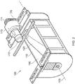
Figure 2 shows a perspective view of a vibropeening apparatus according to an embodiment of the disclosure; -
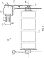
Figure 3 shows an elevational view of the vibropeening apparatus ofFigure 2 ; -
Figure 4 shows a perspective exploded view of the main frame and enclosure of the vibropeening apparatus ofFigure 2 ; and -
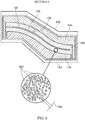
Figure 5 shows a sectional view of the assembled enclosure of the vibropeening apparatus ofFigure 2 . - It is noted that the drawings may not be to scale. The drawings are intended to depict only typical aspects of the disclosure, and therefore should not be considered as limiting the scope of the disclosure. In the drawings, like numbering represents like elements between the drawings.
- Referring to
Figures 2 to 5 , a vibropeening apparatus according to an embodiment of the disclosure is designated generally by thereference numeral 100. - The
vibropeening apparatus 100 has amain frame 110, anenclosure 120 receivable within themain frame 110, arotary drive mechanism 170 and anarticle 180 to be vibropeened. In the present example, thearticle 180 is a fan blade for a turbofan gas turbine engine. - The
main frame 110 takes the form of a rectangular enclosure. In the present arrangement, themain frame 110 is formed as a steel fabrication. However, in alternative arrangements, themain frame 110 may be formed from another metal, such as an aluminium alloy, or from a composite material, such as carbon fibre reinforced composite. - The
enclosure 120 is positioned within themain frame 110 such that it is fully enclosed by themain frame 110, but has sufficient clearance around it that it is able to be rotated around an axis ofrotation 125 of theenclosure 120. In the present arrangement, theenclosure 120 is arranged to be removable from themain frame 110. In other arrangements, theenclosure 120 may be mounted as an integral part of the main frame. - The
enclosure 120 has afirst end 122 and an oppositesecond end 124. Theenclosure 120 has an axis ofrotation 125 that extends between thefirst end 122 and thesecond end 124. Theenclosure 120 rotates about the axis ofrotation 125 when theenclosure 120 is mounted within themain frame 110. - The
rotary drive mechanism 170 is arranged to provide rotary motion to theenclosure 120 within themain frame 110. In the present arrangement, therotary drive mechanism 170 comprises anelectric motor 172 having a drivingportion 174. The drivingportion 174 is connected via atransmission belt 176 to the drivenportion 178. The drivenportion 178 is connected to theenclosure 120 at thefirst end 122 of theenclosure 120. In other arrangements, therotary drive mechanism 170 may comprise any suitable source of rotary motion such as, for example, direct electric drive of theenclosure 120, hydraulic motor drive, hydrostatic motor drive, etc. - As illustrated in
Figure 5 , theenclosure 120 comprises afirst enclosure half 130 and a cooperatingsecond enclosure half 132. Within thefirst enclosure half 130 is located a firstenclosure lining half 134. Within thesecond enclosure half 132 is located a secondenclosure lining half 136. - Each of the
first enclosure half 132 and thesecond enclosure half 134 is formed from a polymeric material. In an alternative arrangement, thefirst enclosure half 132 and thesecond enclosure half 134 may be formed from an alternative material such as, for example, a sheet metal or a fibre reinforced composite material. - Each of the first
enclosure lining half 134 and the secondenclosure lining half 136 is formed from a polyurethane material. In an alternative arrangement, the firstenclosure lining half 134 and the secondenclosure lining half 136 may be formed from another thermoplastic material. - When the
first enclosure half 132 and thesecond enclosure half 134 are assembled together, the firstenclosure lining half 134 and the secondenclosure lining half 136 cooperate to define therebetween aninternal volume 126. Thisinternal volume 126 has the same geometry as thearticle 180 to be vibropeened. - The
internal volume 126 is sized such that when thearticle 180 to be vibropeened is positioned in theinternal volume 126, apredetermined clearance 128 is defined between thearticle 180 and theenclosure 120. Thispredetermined clearance 128 is defined over the entire extent of thearticle 180. - The
article 180 to be vibropeened is attached to thefirst end 122 of theenclosure 120. - The
internal volume 126 accommodates avibropeening bed 160 within which is also located thearticle 180 to be vibropeened. Thevibropeening bed 160 comprises a plurality ofmedia particles 162. In the present arrangement, themedia particles 162 are stainless steel balls having a meanmedia particle size 164, in this case a diameter, of 5mm. - In other arrangements, the
media particles 164 may take the form of a vibropeening media having alternative particle geometry. For example, the media particles may be spherical with a diameter larger or smaller than 5mm. In a further alternative arrangement, the media particle geometry may be cubic, oblate spheroid, pyramidal, or a mixture thereof. - The
enclosure 120 comprises afeed aperture 138 in an external surface. Thefeed aperture 138 allows for the ingress and egress ofmedia particles 162 from theinternal volume 126. - The
enclosure 120 further comprises awindow 140 in an external surface. Thewindow 140 allows a user to visually inspect thevibropeening bed 160 located in theinternal volume 126. - In use, the
article 180 to be vibropeened is attached to thefirst end 122 of theenclosure 120. The firstenclosure lining half 134 and thefirst enclosure half 130 are assembled over one side of thearticle 180. The secondenclosure lining half 136 and thesecond enclosure half 132 are assembled over the opposite side of thearticle 180. - The assembled
enclosure 120 defines aninternal volume 126 between the firstenclosure lining half 134 and the secondenclosure lining half 136, with thearticle 180 being positioned centrally within theinternal volume 126. - The
vibropeening media particles 162 may then be poured into theinternal volume 126 through thefeed aperture 138. - The
rotary drive mechanism 170 provides rotary motion to theenclosure 120. In one arrangement, this rotary motion is a unidirectional rotary motion. In other words, theenclosure 120 always rotates in the same rotational direction. In this arrangement, the rotary motion is approximately 1 to 2 rpm. - In an alternative arrangement, the
rotary drive mechanism 170 provides an oscillatory rotary motion to theenclosure 110. - Upon completion of the vibropeening process, the
vibropeening media particles 162 may be drained from theinternal volume 126 within theenclosure 120 via thefeed aperture 138. Theenclosure 120 may then be removed from themain frame 110. - Disassembly of the
enclosure 110 is the reverse of the assembly process described above. - While the embodiment described relates to the vibropeening of a fan blade for a turbofan gas turbine engine, it is to be understood that the apparatus and method of the present invention are equally applicable to other metallic components requiring vibropeening surface treatment.
- Except where mutually exclusive, any of the features may be employed separately or in combination with any other features and the disclosure extends to and includes all combinations and sub-combinations of one or more features described herein.
- The foregoing description of various aspects of the disclosure has been presented for purposes of illustration and description. It is not intended to be exhaustive or to limit the disclosure to the precise form disclosed, and obviously, many modifications and variations are possible. Such modifications and variations that may be apparent to a person of skill in the art are included within the scope of the disclosure as defined by the accompanying claims.
Claims (15)
- A vibropeening apparatus (100) comprising:a main frame (110);an enclosure (120) receivable within the main frame (110):wherein the enclosure (120) defines an internal volume (126), the internal volume (126) accommodating a vibropeening bed (160), the article (180) being positioned within the internal volume (126), and the rotary drive mechanism (170) being configured to impart a rotary motion to the enclosure (120) within the main frame (110).a rotary drive mechanism (170); andan article (180) to be vibropeened,
- The apparatus (100) as claimed in Claim 1, wherein when the article (180) is positioned within the internal volume (126), a predetermined clearance (128) is defined between the article (180) and the enclosure (120).
- The apparatus (100) as claimed in Claim 1 or Claim 2, wherein the vibropeening bed (160) comprises a plurality of media particles (162), the media particles (162) having a mean media particle size (164).
- The apparatus (100) as claimed in Claim 3, wherein the predetermined clearance (128) is approximately between five (5) and ten (10) times the mean media particle size (164).
- The apparatus (100) as claimed in any one of Claims 1 to 4, wherein the enclosure (120) is removably mounted within the main frame (110).
- The apparatus (100) as claimed in any one of Claims 1 to 5, wherein the enclosure (120) comprises a feed aperture (138), the feed aperture (138) allowing for the ingress and egress of media particles (162).
- The apparatus (100) as claimed in any one of Claims 1 to 6, wherein the enclosure (120) comprises an inner surface, the inner surface being formed from a thermoplastic polymeric material.
- The apparatus (100) as claimed in any one of Claims 1 to 7, the enclosure (120) further comprising a first end (122) and an opposite second end (124), and an axis of rotation (125) extending between the first end (122) and the second end (124), and wherein the article (180) is removably secured to an internal surface of the first end (122) of the enclosure (120).
- The apparatus (100) as claimed in any one of Claims 1 to 7, wherein the enclosure (120) further comprises a window (140) allowing a visual inspection of the vibropeening bed (160).
- The apparatus (100) as claimed in any one of Claims 1 to 9, wherein the rotary motion is a unidirectional rotary motion.
- The apparatus (100) as claimed in any one of Claims 1 to 9, wherein the rotary motion is an oscillatory rotary motion.
- A method of using a vibropeening apparatus (100), the apparatus (100) comprising a main frame (110), an enclosure (120) receivable within the main frame (110), and a rotary drive mechanism (170) configured to rotate the enclosure (120), the method comprising the steps of:providing a vibropeening bed (160) within the enclosure (120);positioning an article (180) to be vibropeened within the vibropeening bed (160);actuating the vibropeening bed (160); androtating the enclosure (120) within the main frame (110).
- The method as claimed in Claim 12, wherein the step of positioning an article (180) to be vibropeened within the enclosure (120), comprises the step of:positioning an article (180) to be vibropeened within the enclosure (120) such that a predetermined clearance (128) is defined between the article (180) and the enclosure (120).
- The method as claimed in Claim 12 or Claim 13, wherein the step of positioning an article (180) to be vibropeened within the enclosure (120), comprises the additional following step of:attaching the article (180) to one end of the enclosure (120).
- The method as claimed in any one of Claims 12 to 14, wherein the step of rotating the enclosure (120) comprises the step of:rotating the enclosure (120) in a unidirectional manner.
Applications Claiming Priority (1)
| Application Number | Priority Date | Filing Date | Title |
|---|---|---|---|
| GBGB1609621.6A GB201609621D0 (en) | 2016-06-02 | 2016-06-02 | A vibropeening system and a method of using the same |
Publications (2)
| Publication Number | Publication Date |
|---|---|
| EP3251792A2 true EP3251792A2 (en) | 2017-12-06 |
| EP3251792A3 EP3251792A3 (en) | 2018-05-16 |
Family
ID=56507949
Family Applications (1)
| Application Number | Title | Priority Date | Filing Date |
|---|---|---|---|
| EP17173804.0A Withdrawn EP3251792A3 (en) | 2016-06-02 | 2017-05-31 | A vibropeening system and a method of using the same |
Country Status (3)
| Country | Link |
|---|---|
| US (1) | US9969034B2 (en) |
| EP (1) | EP3251792A3 (en) |
| GB (1) | GB201609621D0 (en) |
Cited By (1)
| Publication number | Priority date | Publication date | Assignee | Title |
|---|---|---|---|---|
| CN110238747A (en) * | 2019-06-21 | 2019-09-17 | 中国航空制造技术研究院 | Process and frock clamp for complex profile blade surface light decorations |
Families Citing this family (2)
| Publication number | Priority date | Publication date | Assignee | Title |
|---|---|---|---|---|
| TWI797922B (en) * | 2021-12-28 | 2023-04-01 | 國家中山科學研究院 | Adjustable Fluid Grinding Fixture |
| GB202217181D0 (en) * | 2022-11-17 | 2023-01-04 | Rolls Royce Plc | System and method for controlling a treatment process |
Family Cites Families (10)
| Publication number | Priority date | Publication date | Assignee | Title |
|---|---|---|---|---|
| US2734316A (en) * | 1954-11-22 | 1956-02-14 | dawson | |
| US2809473A (en) | 1955-02-15 | 1957-10-15 | Concrete Grinding Corp | Apparatus for smoothing the surfaces of articles |
| US4263797A (en) * | 1979-01-23 | 1981-04-28 | Cooper Roger H | Method of reclaiming used railroad spikes |
| SU984832A1 (en) * | 1981-02-26 | 1982-12-30 | Предприятие П/Я А-3438 | Vibration working method |
| FR2505710A1 (en) * | 1981-05-18 | 1982-11-19 | Gornometallurgichesky Inst | Vibratory component surface treat unit - has individual cells contg. abrasive at periphery of drum rotating in and vibrating with housing |
| US5018312A (en) * | 1987-07-09 | 1991-05-28 | Al Steckis | Deflashing apparatus |
| RU2009848C1 (en) | 1991-10-15 | 1994-03-30 | Раид Минулович Халимулин | Vibration machine |
| US5950470A (en) * | 1998-09-09 | 1999-09-14 | United Technologies Corporation | Method and apparatus for peening the internal surface of a non-ferromagnetic hollow part |
| MX2016016933A (en) * | 2014-07-22 | 2017-04-25 | Sintokogio Ltd | Shot peening device. |
| WO2016062856A1 (en) | 2014-10-24 | 2016-04-28 | Tecnolook S.R.L. | Barrel finishing device |
-
2016
- 2016-06-02 GB GBGB1609621.6A patent/GB201609621D0/en not_active Ceased
-
2017
- 2017-05-31 US US15/610,042 patent/US9969034B2/en not_active Expired - Fee Related
- 2017-05-31 EP EP17173804.0A patent/EP3251792A3/en not_active Withdrawn
Cited By (1)
| Publication number | Priority date | Publication date | Assignee | Title |
|---|---|---|---|---|
| CN110238747A (en) * | 2019-06-21 | 2019-09-17 | 中国航空制造技术研究院 | Process and frock clamp for complex profile blade surface light decorations |
Also Published As
| Publication number | Publication date |
|---|---|
| US20170348809A1 (en) | 2017-12-07 |
| GB201609621D0 (en) | 2016-07-20 |
| EP3251792A3 (en) | 2018-05-16 |
| US9969034B2 (en) | 2018-05-15 |
Similar Documents
| Publication | Publication Date | Title |
|---|---|---|
| US9969034B2 (en) | Vibropeening system and a method of using the same | |
| EP3053731B1 (en) | Methods of manufacturing and cleaning | |
| US8657647B2 (en) | Method of polishing bladed disks for a turbomachine and polishing device | |
| CN106413989B (en) | Airfoil mechanical component polishing method | |
| US20110179843A1 (en) | Method for hardening the surface of a component in a wind turbine | |
| CA2709474C (en) | Peen finishing | |
| EP3659721A1 (en) | Finishing a surface of a component made by additive manufacturing | |
| EP3513903B1 (en) | Fan blade of a gas turbine engine | |
| JPH0547177B2 (en) | ||
| JP2016536007A (en) | Animal skin separator | |
| WO2012164322A1 (en) | Cavitation equipment to produce heated liquids, and procedure for the operation thereof | |
| CN210255755U (en) | A high-frequency pulse current-assisted surface shot peening processing device | |
| CN110678299A (en) | Dust cleaning device for cooling air cleaning of electric tools | |
| US11466702B2 (en) | Pump assembly | |
| EP3251793B1 (en) | Vibratory treatment apparatus and method of vibratory treatment | |
| EP3856458B1 (en) | Operating head with electro spindles | |
| CN220296744U (en) | Dysmorphism reinforcing bar welded mesh grinding device | |
| US2734316A (en) | dawson | |
| CN115106922A (en) | Drum grinding device and drum grinding method | |
| GB2545956A (en) | Vibro-Polishing Arrangement | |
| JP6379682B2 (en) | Centrifuge | |
| CN213647180U (en) | A sand blasting equipment for auto-parts | |
| EP2436487A1 (en) | Method and system for the peening and vibratory finishing of gears | |
| CN115485399A (en) | Method for treating the surface of a metal part of a turbomachine | |
| CN203853891U (en) | Shot blasting machine |
Legal Events
| Date | Code | Title | Description |
|---|---|---|---|
| PUAI | Public reference made under article 153(3) epc to a published international application that has entered the european phase |
Free format text: ORIGINAL CODE: 0009012 |
|
| STAA | Information on the status of an ep patent application or granted ep patent |
Free format text: STATUS: THE APPLICATION HAS BEEN PUBLISHED |
|
| AK | Designated contracting states |
Kind code of ref document: A2 Designated state(s): AL AT BE BG CH CY CZ DE DK EE ES FI FR GB GR HR HU IE IS IT LI LT LU LV MC MK MT NL NO PL PT RO RS SE SI SK SM TR |
|
| AX | Request for extension of the european patent |
Extension state: BA ME |
|
| PUAL | Search report despatched |
Free format text: ORIGINAL CODE: 0009013 |
|
| AK | Designated contracting states |
Kind code of ref document: A3 Designated state(s): AL AT BE BG CH CY CZ DE DK EE ES FI FR GB GR HR HU IE IS IT LI LT LU LV MC MK MT NL NO PL PT RO RS SE SI SK SM TR |
|
| AX | Request for extension of the european patent |
Extension state: BA ME |
|
| RIC1 | Information provided on ipc code assigned before grant |
Ipc: B24B 31/00 20060101AFI20180411BHEP Ipc: B24B 19/14 20060101ALI20180411BHEP |
|
| STAA | Information on the status of an ep patent application or granted ep patent |
Free format text: STATUS: REQUEST FOR EXAMINATION WAS MADE |
|
| 17P | Request for examination filed |
Effective date: 20181109 |
|
| RBV | Designated contracting states (corrected) |
Designated state(s): AL AT BE BG CH CY CZ DE DK EE ES FI FR GB GR HR HU IE IS IT LI LT LU LV MC MK MT NL NO PL PT RO RS SE SI SK SM TR |
|
| STAA | Information on the status of an ep patent application or granted ep patent |
Free format text: STATUS: EXAMINATION IS IN PROGRESS |
|
| 17Q | First examination report despatched |
Effective date: 20190329 |
|
| RAP1 | Party data changed (applicant data changed or rights of an application transferred) |
Owner name: ROLLS-ROYCE DEUTSCHLAND LTD & CO KG Owner name: ROLLS-ROYCE PLC |
|
| STAA | Information on the status of an ep patent application or granted ep patent |
Free format text: STATUS: THE APPLICATION IS DEEMED TO BE WITHDRAWN |
|
| 18D | Application deemed to be withdrawn |
Effective date: 20201201 |