EP3251573B1 - Two-stage dust-air separation structure and dust cup comprising same - Google Patents
Two-stage dust-air separation structure and dust cup comprising same Download PDFInfo
- Publication number
- EP3251573B1 EP3251573B1 EP15879701.9A EP15879701A EP3251573B1 EP 3251573 B1 EP3251573 B1 EP 3251573B1 EP 15879701 A EP15879701 A EP 15879701A EP 3251573 B1 EP3251573 B1 EP 3251573B1
- Authority
- EP
- European Patent Office
- Prior art keywords
- dust
- stage
- air
- barrel
- cyclone
- Prior art date
- Legal status (The legal status is an assumption and is not a legal conclusion. Google has not performed a legal analysis and makes no representation as to the accuracy of the status listed.)
- Active
Links
Images




Classifications
-
- B—PERFORMING OPERATIONS; TRANSPORTING
- B04—CENTRIFUGAL APPARATUS OR MACHINES FOR CARRYING-OUT PHYSICAL OR CHEMICAL PROCESSES
- B04C—APPARATUS USING FREE VORTEX FLOW, e.g. CYCLONES
- B04C5/00—Apparatus in which the axial direction of the vortex is reversed
- B04C5/24—Multiple arrangement thereof
- B04C5/26—Multiple arrangement thereof for series flow
-
- A—HUMAN NECESSITIES
- A47—FURNITURE; DOMESTIC ARTICLES OR APPLIANCES; COFFEE MILLS; SPICE MILLS; SUCTION CLEANERS IN GENERAL
- A47L—DOMESTIC WASHING OR CLEANING; SUCTION CLEANERS IN GENERAL
- A47L9/00—Details or accessories of suction cleaners, e.g. mechanical means for controlling the suction or for effecting pulsating action; Storing devices specially adapted to suction cleaners or parts thereof; Carrying-vehicles specially adapted for suction cleaners
- A47L9/10—Filters; Dust separators; Dust removal; Automatic exchange of filters
- A47L9/12—Dry filters
- A47L9/127—Dry filters tube- or sleeve-shaped
-
- A—HUMAN NECESSITIES
- A47—FURNITURE; DOMESTIC ARTICLES OR APPLIANCES; COFFEE MILLS; SPICE MILLS; SUCTION CLEANERS IN GENERAL
- A47L—DOMESTIC WASHING OR CLEANING; SUCTION CLEANERS IN GENERAL
- A47L9/00—Details or accessories of suction cleaners, e.g. mechanical means for controlling the suction or for effecting pulsating action; Storing devices specially adapted to suction cleaners or parts thereof; Carrying-vehicles specially adapted for suction cleaners
- A47L9/10—Filters; Dust separators; Dust removal; Automatic exchange of filters
- A47L9/12—Dry filters
- A47L9/122—Dry filters flat
-
- A—HUMAN NECESSITIES
- A47—FURNITURE; DOMESTIC ARTICLES OR APPLIANCES; COFFEE MILLS; SPICE MILLS; SUCTION CLEANERS IN GENERAL
- A47L—DOMESTIC WASHING OR CLEANING; SUCTION CLEANERS IN GENERAL
- A47L9/00—Details or accessories of suction cleaners, e.g. mechanical means for controlling the suction or for effecting pulsating action; Storing devices specially adapted to suction cleaners or parts thereof; Carrying-vehicles specially adapted for suction cleaners
- A47L9/10—Filters; Dust separators; Dust removal; Automatic exchange of filters
- A47L9/16—Arrangement or disposition of cyclones or other devices with centrifugal action
- A47L9/1608—Cyclonic chamber constructions
-
- A—HUMAN NECESSITIES
- A47—FURNITURE; DOMESTIC ARTICLES OR APPLIANCES; COFFEE MILLS; SPICE MILLS; SUCTION CLEANERS IN GENERAL
- A47L—DOMESTIC WASHING OR CLEANING; SUCTION CLEANERS IN GENERAL
- A47L9/00—Details or accessories of suction cleaners, e.g. mechanical means for controlling the suction or for effecting pulsating action; Storing devices specially adapted to suction cleaners or parts thereof; Carrying-vehicles specially adapted for suction cleaners
- A47L9/10—Filters; Dust separators; Dust removal; Automatic exchange of filters
- A47L9/16—Arrangement or disposition of cyclones or other devices with centrifugal action
- A47L9/165—Construction of inlets
-
- A—HUMAN NECESSITIES
- A47—FURNITURE; DOMESTIC ARTICLES OR APPLIANCES; COFFEE MILLS; SPICE MILLS; SUCTION CLEANERS IN GENERAL
- A47L—DOMESTIC WASHING OR CLEANING; SUCTION CLEANERS IN GENERAL
- A47L9/00—Details or accessories of suction cleaners, e.g. mechanical means for controlling the suction or for effecting pulsating action; Storing devices specially adapted to suction cleaners or parts thereof; Carrying-vehicles specially adapted for suction cleaners
- A47L9/10—Filters; Dust separators; Dust removal; Automatic exchange of filters
- A47L9/16—Arrangement or disposition of cyclones or other devices with centrifugal action
- A47L9/1683—Dust collecting chambers; Dust collecting receptacles
-
- B—PERFORMING OPERATIONS; TRANSPORTING
- B01—PHYSICAL OR CHEMICAL PROCESSES OR APPARATUS IN GENERAL
- B01D—SEPARATION
- B01D45/00—Separating dispersed particles from gases or vapours by gravity, inertia, or centrifugal forces
- B01D45/04—Separating dispersed particles from gases or vapours by gravity, inertia, or centrifugal forces by utilising inertia
- B01D45/06—Separating dispersed particles from gases or vapours by gravity, inertia, or centrifugal forces by utilising inertia by reversal of direction of flow
-
- B—PERFORMING OPERATIONS; TRANSPORTING
- B01—PHYSICAL OR CHEMICAL PROCESSES OR APPARATUS IN GENERAL
- B01D—SEPARATION
- B01D45/00—Separating dispersed particles from gases or vapours by gravity, inertia, or centrifugal forces
- B01D45/12—Separating dispersed particles from gases or vapours by gravity, inertia, or centrifugal forces by centrifugal forces
- B01D45/14—Separating dispersed particles from gases or vapours by gravity, inertia, or centrifugal forces by centrifugal forces generated by rotating vanes, discs, drums or brushes
-
- B—PERFORMING OPERATIONS; TRANSPORTING
- B01—PHYSICAL OR CHEMICAL PROCESSES OR APPARATUS IN GENERAL
- B01D—SEPARATION
- B01D45/00—Separating dispersed particles from gases or vapours by gravity, inertia, or centrifugal forces
- B01D45/12—Separating dispersed particles from gases or vapours by gravity, inertia, or centrifugal forces by centrifugal forces
- B01D45/16—Separating dispersed particles from gases or vapours by gravity, inertia, or centrifugal forces by centrifugal forces generated by the winding course of the gas stream, the centrifugal forces being generated solely or partly by mechanical means, e.g. fixed swirl vanes
-
- B—PERFORMING OPERATIONS; TRANSPORTING
- B01—PHYSICAL OR CHEMICAL PROCESSES OR APPARATUS IN GENERAL
- B01D—SEPARATION
- B01D46/00—Filters or filtering processes specially modified for separating dispersed particles from gases or vapours
- B01D46/56—Filters or filtering processes specially modified for separating dispersed particles from gases or vapours with multiple filtering elements, characterised by their mutual disposition
- B01D46/62—Filters or filtering processes specially modified for separating dispersed particles from gases or vapours with multiple filtering elements, characterised by their mutual disposition connected in series
-
- B—PERFORMING OPERATIONS; TRANSPORTING
- B01—PHYSICAL OR CHEMICAL PROCESSES OR APPARATUS IN GENERAL
- B01D—SEPARATION
- B01D50/00—Combinations of methods or devices for separating particles from gases or vapours
- B01D50/20—Combinations of devices covered by groups B01D45/00 and B01D46/00
-
- B—PERFORMING OPERATIONS; TRANSPORTING
- B04—CENTRIFUGAL APPARATUS OR MACHINES FOR CARRYING-OUT PHYSICAL OR CHEMICAL PROCESSES
- B04C—APPARATUS USING FREE VORTEX FLOW, e.g. CYCLONES
- B04C9/00—Combinations with other devices, e.g. fans, expansion chambers, diffusors, water locks
-
- B—PERFORMING OPERATIONS; TRANSPORTING
- B04—CENTRIFUGAL APPARATUS OR MACHINES FOR CARRYING-OUT PHYSICAL OR CHEMICAL PROCESSES
- B04C—APPARATUS USING FREE VORTEX FLOW, e.g. CYCLONES
- B04C3/00—Apparatus in which the axial direction of the vortex flow following a screw-thread type line remains unchanged ; Devices in which one of the two discharge ducts returns centrally through the vortex chamber, a reverse-flow vortex being prevented by bulkheads in the central discharge duct
- B04C2003/006—Construction of elements by which the vortex flow is generated or degenerated
-
- B—PERFORMING OPERATIONS; TRANSPORTING
- B04—CENTRIFUGAL APPARATUS OR MACHINES FOR CARRYING-OUT PHYSICAL OR CHEMICAL PROCESSES
- B04C—APPARATUS USING FREE VORTEX FLOW, e.g. CYCLONES
- B04C9/00—Combinations with other devices, e.g. fans, expansion chambers, diffusors, water locks
- B04C2009/004—Combinations with other devices, e.g. fans, expansion chambers, diffusors, water locks with internal filters, in the cyclone chamber or in the vortex finder
-
- B—PERFORMING OPERATIONS; TRANSPORTING
- B04—CENTRIFUGAL APPARATUS OR MACHINES FOR CARRYING-OUT PHYSICAL OR CHEMICAL PROCESSES
- B04C—APPARATUS USING FREE VORTEX FLOW, e.g. CYCLONES
- B04C3/00—Apparatus in which the axial direction of the vortex flow following a screw-thread type line remains unchanged ; Devices in which one of the two discharge ducts returns centrally through the vortex chamber, a reverse-flow vortex being prevented by bulkheads in the central discharge duct
- B04C3/04—Multiple arrangement thereof
-
- B—PERFORMING OPERATIONS; TRANSPORTING
- B04—CENTRIFUGAL APPARATUS OR MACHINES FOR CARRYING-OUT PHYSICAL OR CHEMICAL PROCESSES
- B04C—APPARATUS USING FREE VORTEX FLOW, e.g. CYCLONES
- B04C3/00—Apparatus in which the axial direction of the vortex flow following a screw-thread type line remains unchanged ; Devices in which one of the two discharge ducts returns centrally through the vortex chamber, a reverse-flow vortex being prevented by bulkheads in the central discharge duct
- B04C3/06—Construction of inlets or outlets to the vortex chamber
Definitions
- the present application relates to the field of manufacturing technology of dust collectors, and in particular to a two-stage dust-air separation structure and a dust cup having the structure.
- a dust collector is a cleaning appliance which utilizes a motor to drive vanes to rotate at a high speed to generate an air negative pressure in a sealed housing, so as to suction dust into a dust collecting device and discharge the filtered air out of a fan at an extremely high speed.
- the dust collectors are classified into dry type dust collectors and wet-dry type dust collectors according their functions.
- the dry type dust collectors generally include a dust-bag type dust collector and a dust-cup type dust collector.
- a conventional dust-cup type dust collector generally includes a two-stage dust-air separation structure.
- a first-stage structure is used to filter large size dirt in air, and a second-stage structure is used to separate and collect small size debris such as dust particles.
- a two-stage cyclone is generally generated by the cooperation between a cover plate of a dust cup filter and a cyclone body having multiple cyclone openings, and this structure requires a lot of components, which also requires many and complicated molds and assembly processes. Further, the sealing of each link is difficult to control, and air leakage and dust leakage phenomena are apt to occur, which adversely affects the comprehensive performance of the whole machine.
- a conventional two-stage dust-air separation type dust cup structure is arranged axially, in which multiple layers of cone bodies and a cyclone partition plate are axially stacked to achieve an object of separating dust from the gas, thus its filter structure occupies a large proportion of space of the dust cup and occupies too much of the dust-collecting volume of the dust cup, and a dust storage space is limited.
- this two-stage dust-air separation type dust cup structure requires the dust cup to have a relatively high size and a relatively large volume, and is not applicable to a mini dust collector and a portable dust collector, and the application scope thereof is limited.
- air leakage and dust leakage phenomena are apt to occur, which adversely affects the comprehensive performance of the whole machine.
- Prior art EP 2508265A1 discloses a dust collecting apparatus, which comprises: a filter assembly arranged in an upper portion of the second cyclone unit, and including a filter member which separates fine dust from the air discharged from the second cyclone unit; and a dust-removing unit to separate dust accumulated in the filter member, wherein the dust separated from the filter member is collected into the second centrifugal separation chamber through the second cyclone discharge pipe.
- a dust collecting apparatus which comprises: a filter assembly arranged in an upper portion of the second cyclone unit, and including a filter member which separates fine dust from the air discharged from the second cyclone unit; and a dust-removing unit to separate dust accumulated in the filter member, wherein the dust separated from the filter member is collected into the second centrifugal separation chamber through the second cyclone discharge pipe.
- a a dust cup is provided according to the present application, to reduce the number of the components, simplify the assembly process, improve the comprehensive performance of the whole machine, and also effectively reduce the space of the dust cup that is occupied by a two-stage dust-air separation structure, to realize the maximum dust storage volume and improve the dust collecting efficiency, thereby allowing the two-stage dust-air separation structure to be applicable to dust collectors of various types and sizes.
- a dust cup comprising a cup body and a two-stage dust-air separation structure arranged inside the cup body, an air inlet and an air outlet are arranged in a sidewall of the cup body, wherein,
- the spiral impeller has a plurality of downward-inclined vanes, and the vanes are configured to constrain the dusty air to flow obliquely downwards.
- the spiral dust-air separation device further includes an inner ring arranged on an inner periphery of the spiral impeller, a plurality of guidance tangent planes are arranged on a side wall, corresponding to an air outlet of the spiral impeller, of the inner ring, to constrain the dusty air to flow to an outer periphery of the spiral impeller to begin to form a rotating state.
- a wall of the inner ring of the spiral impeller extends downwards to form a wind shielding plate.
- a lower part of the second-stage cyclone barrel extends obliquely to a center of the barrel bottom of the second-stage cyclone barrel to form a conical hole.
- a gap is provided between a bottom of the dust retaining barrel and the conical hole, and the bottom of the dust retaining barrel and the conical hole are fixedly connected by a plurality of strip ribs to allow the dust to stop rotating at the strip ribs, a space between the gap and the strip ribs forms a second-stage dust inlet.
- the second-stage dust collecting space is configured as a second-stage dust collecting barrel arranged below the second-stage cyclone barrel, the conical hole extends to the second-stage dust collecting barrel and partially extends into an inside of the second-stage dust collecting barrel to form a dust retaining flange of the second-stage dust collecting barrel.
- an overall air-intake area of the spiral impeller is less than an air-outgoing area of the dust cup, to allow a centrifugal force generated by rotation to be sufficient to resist a suction of the negative pressure.
- a central part of the return-air dust guard protrudes upward to form an air guiding cone for guiding return air.
- the dust cup according to the present application has the following advantages.
- the structure includes a cyclone separator and a spiral dust-air separation device.
- a first stage separation of dust from air is realized by a cyclone housing, and by arranging a second-stage cyclone barrel inside the cyclone housing and arranging the spiral dust-air separation device at a barrel opening of the second-stage cyclone barrel, the dusty air, after going through the first stage separation, is guided by the spiral dust-air separation device to form, on an inner wall of the second-stage cyclone barrel, an airflow rotating towards the barrel bottom, and the dust in the airflow is driven by a centrifugal force to rotate downwardly to the barrel bottom and be collected in a second-stage dust collecting space, and the air in the rotating airflow is extracted by a negative pressure, thereby realizing a second stage separation of dust from air.
- the two-stage dust-air separation structure only includes the cyclone housing, the second-stage cyclone and the spiral dust-air separation device, hence, the number of components is effectively reduced, and the assembly process is simplified, which facilitates the improvement of the comprehensive performance of the whole machine.
- the structure has a small volume, thus can effectively reduce the space of the dust cup that is occupied by the two separation structure, realize the maximum dust storage volume and improve the dust collecting efficiency, and is applicable to dust collectors of various types and sizes.
- a conventional two-stage dust-air separation structure requires a lot of components, and relatively many and complicated molds and assembly processes, and the sealing of each of link is difficult to control, thus air leakage and dust leakage phenomena are apt to occur, which adversely affects the comprehensive performance of the whole machine.
- a conventional two-stage dust-air separation type dust cup structure is axially arranged, and its filter structure occupies a large portion of the space of the dust cup and occupies too much of the dust collecting volume of the dust cup, and a dust storage space is limited.
- this two-stage dust-air separation dust cup structure requires the dust cup to have a relatively high size and a relatively large volume, thus is not applicable to a mini dust collector and a portable dust collector, and the application scope thereof is limited.
- a two-stage dust-air separation structure and a dust cup having the structure are provided according to the present application, to reduce the number of the components, simplify the assembly process, improve the comprehensive performance of the whole machine, and also effectively reduce the space of the dust cup that is occupied by the two-stage separation structure, to realize the maximum dust storage volume and improve the dust collecting efficiency, thereby allowing the two-stage dust-air separation structure to be applicable to dust collectors of various types and sizes.
- a two-stage dust-air separation structure which includes a cyclone separator 210 and a spiral dust-air separation device 220.
- the cyclone separator 210 includes a cyclone housing 211 for a first stage dust-air separation and a second-stage cyclone barrel 212 arranged inside the cyclone housing 211.
- a gap is provided between the second-stage cyclone barrel and an inner wall of the cyclone housing, and the gap is configured to form an air-intake duct 213 for introducing the gas after being separated in the first stage dust-air separation.
- Filter holes 230 are arranged in the cyclone housing, and after entering from an air inlet, the dusty air firstly passes through the filter holes 230 to allow large sized debris to be removed and collected in a first stage collecting barrel 110, and the air after going through the first stage separation enters the air-intake duct 213.
- a spiral groove 232 is arranged in an inner side of an upper end of the cyclone housing, such that airflow rotates there and generates a centrifugal force to facilitate airflow's rotating downwards and entering the spiral dust-air separation device.
- the spiral dust-air separation device 220 is arranged at a barrel opening of the second-stage cyclone barrel 212, and an opening connected to a second-stage dust collecting space is further provided at a barrel bottom of the second-stage cyclone barrel 212, and the second-stage dust collecting space is a second-stage dust collecting barrel 214.
- the dusty air After the dusty air has gone through the first stage dust-air separation performed by the cyclone housing 211, at least part of the dusty air is guided to the spiral dust-air separation device 220 through the air-intake duct 213, and is guided by the spiral dust-air separation device to form, on an inner wall of the second-stage cyclone barrel 212, an airflow rotating towards the barrel bottom, the dust in the airflow is driven by the centrifugal force to rotate downwardly to the barrel bottom and be collected in the second-stage dust collecting barrel 214, and the air in the rotating airflow is extracted by a negative pressure, thereby realizing the second stage dust-air separation.
- the spiral dust-air separation device 220 includes a spiral impeller 221 configured to generate a second-stage cyclone.
- the spiral impeller 221 has multiple downward-inclined vanes, and the vanes can constrain the dusty air to flow obliquely downwards to form a spiral airflow.
- the spiral dust-air separation device 220 further includes an inner ring 222 arranged on an inner periphery of the spiral impeller 221.
- Several guidance tangent planes are arranged on a side wall, corresponding to an air outlet of the spiral impeller 221, of the inner ring 22.
- the guidance tangent planes can constrain the dusty air to flow to an outer periphery of the spiral impeller to begin to form a rotating state.
- An outer ring is arranged at an outer periphery of the spiral impeller. The airflow is guided by the inner ring and the outer ring, which improves the structural strength and stability of the spiral impeller.
- a wall of the inner ring of the spiral impeller may extend downwards to form a wind shielding plate 225.
- the cyclone separator 210 further includes an inverted dust retaining barrel 215 arranged inside the second-stage cyclone barrel 212, a gap is provided between the dust retaining barrel and the second-stage cyclone barrel, and the gap is configured to form a second-stage dust-air separation duct 216.
- the dusty air rotates spirally in the second-stage dust-air separation duct to generate a centrifugal force, to enable the dust to fall down along the inner wall of the second-stage cyclone barrel.
- An inner side wall of the dust retaining barrel is configured to constrain the dusty air to rotate in the dust retaining barrel to generate a centrifugal force to resist suction of the negative pressure, thereby realizing an effective separation of dust from air.
- a lower part of the second-stage cyclone barrel extends obliquely to the center of the bottom to form a conical hole 217, to enable the dust to fall into the second-stage dust collecting barrel under the guidance of the conical hole.
- a gap is provided between a bottom of the dust retaining barrel 215 and the conical hole 217, and the bottom of the dust retaining barrel 215 and the conical hole are fixedly connected by multiple strip ribs 218 to enable the dust to stop rotating at the strip ribs, and facilitate the dust's falling down.
- the space between the gap and the strip ribs forms a second-stage dust inlet 231, and the dust after going through the second stage dust-air separation falls into the second-stage dust collecting space via the second-stage dust inlet.
- the number of the strip ribs uniformly arranged surrounding the dust retaining barrel may be one, two, three or more, and the specific number is not limited.
- the conical hole 217 extends to the second-stage dust collecting barrel 214 and partially extends into the inside of the second-stage dust collecting barrel to form a dust retaining flange 219 of the second-stage dust collecting barrel, to prevent the dust from flowing back.
- the dust retaining flange may generally be designed to extend to a position within an inner side of a projection of the dust retaining barrel, to ensure the effectiveness of dust retaining, and the specific extended position is not limited.
- the cyclone separator and the spiral dust-air separation device may both have an integrally formed structure. After being formed, the spiral dust-air separation device is directly mounted at the center of the cyclone separator and the assembly is just completed.
- the specific forming manner is not limited.
- the two-stage dust-air separation structure may also be integrally formed, and the specific forming and assembling manner is not limited.
- a dust cup which includes a cup body 100 and a two-stage dust-air separation structure 200 arranged inside the cup body 100.
- a space between the cup body and the two-stage dust-air separation structure forms a first-stage dust collecting barrel 110 for collecting large sized debris.
- An air inlet 120 and an air outlet 130 are arranged in a sidewall of the cup body, dusty air is guided by the air inlet to the cyclone separator of the two-stage dust-air separation structure, and after the dusty air has gone through a first stage dust-air separation performed by a cyclone housing 211, at least part of the dusty air enters the second-stage cyclone barrel 212 through the cyclone housing, to proceed to a second stage dust-air separation.
- An overall air-intake area of the spiral impeller is less than an air-outgoing area of the dust cup, to enable the dusty air to have a higher rotation speed in the case that the volume of air is constant, to resist the suction of the negative pressure.
- a partition plate 140 is arranged inside the cup body, a center of the partition plate extends downward to form an opening 150.
- a return-air dust guard 160 is provided on the opening and above the spiral impeller, the return-air dust guard is fixedly connected to an edge of the opening by several cyclone ribs 170 arranged on a periphery of the return-air dust guard, and the air gone through the second stage dust-air separation is extracted by a negative pressure through gaps between the cyclone ribs.
- the partition plate By providing the partition plate to shield an upper end of the cyclone housing, the dusty air after being filtered by the cyclone housing may be guided from an upper end of the air-intake duct into the spiral dust-air separation device, to realize guidance to the ingoing air.
- a central part of the partition plate has a downward-inclined curved structure, to facilitate guiding the movement of the dusty air.
- a central part of the return-air dust guard 160 protrudes upward to form an air guiding cone 180 to realize guidance to the return air.
- the dusty air gone through the second stage separation still keeps a high-speed rotating state when passing through the return-air dust guard.
- a bottom of the return-air dust guard has a crimping to achieve quick assembling of the return-air dust guard with the dust retaining barrel and realize effective centering.
- a two-stage dust-air separation structure and a dust cup having the structure are provided according to the present application, and the structure includes a cyclone separator and a spiral dust-air separation device.
- a first stage separation of dust from air is realized by a cyclone housing, and by arranging a second-stage cyclone barrel inside the cyclone housing and arranging the spiral dust-air separation device at a barrel opening of the second-stage cyclone barrel, the dusty air, after going through the first stage separation, is guided by the spiral dust-air separation device to form, on an inner wall of the second-stage cyclone barrel, an airflow rotating towards the barrel bottom, and the dust in the airflow is driven by a centrifugal force to rotate downwardly to the barrel bottom and be collected in a second-stage dust collecting space, and the air in the rotating airflow is extracted by the negative pressure, thereby realizing a second stage separation of dust from air.
- the two-stage dust-air separation structure only includes the cyclone housing, the second-stage cyclone and the spiral dust-air separation device, hence, the number of components is effectively reduced, and the assembly process is simplified, which facilitates the improvement of the comprehensive performance of the whole machine.
- the structure has a small volume, thus can effectively reduce the space of the dust cup that is occupied by the two separation structure, realize the maximum dust storage volume and improve the dust collecting efficiency, and is applicable to dust collectors of various types and sizes.
Landscapes
- Engineering & Computer Science (AREA)
- Mechanical Engineering (AREA)
- Chemical & Material Sciences (AREA)
- Chemical Kinetics & Catalysis (AREA)
- Filters For Electric Vacuum Cleaners (AREA)
- Cyclones (AREA)
- Filtering Of Dispersed Particles In Gases (AREA)
Description
- This application claims the benefit of priority to
Chinese Patent Application No. 201510044589.X, titled "TWO-STAGE DUST-GAS SEPARATION STRUCTURE AND DUST CUP HAVING SAME", filed with the State Intellectual Property Office of People's Republic of China on January 28, 2015 - The present application relates to the field of manufacturing technology of dust collectors, and in particular to a two-stage dust-air separation structure and a dust cup having the structure.
- A dust collector is a cleaning appliance which utilizes a motor to drive vanes to rotate at a high speed to generate an air negative pressure in a sealed housing, so as to suction dust into a dust collecting device and discharge the filtered air out of a fan at an extremely high speed. The dust collectors are classified into dry type dust collectors and wet-dry type dust collectors according their functions. The dry type dust collectors generally include a dust-bag type dust collector and a dust-cup type dust collector.
- A conventional dust-cup type dust collector generally includes a two-stage dust-air separation structure. A first-stage structure is used to filter large size dirt in air, and a second-stage structure is used to separate and collect small size debris such as dust particles. In a conventional two-stage dust-air separation structure, a two-stage cyclone is generally generated by the cooperation between a cover plate of a dust cup filter and a cyclone body having multiple cyclone openings, and this structure requires a lot of components, which also requires many and complicated molds and assembly processes. Further, the sealing of each link is difficult to control, and air leakage and dust leakage phenomena are apt to occur, which adversely affects the comprehensive performance of the whole machine.
- A conventional two-stage dust-air separation type dust cup structure is arranged axially, in which multiple layers of cone bodies and a cyclone partition plate are axially stacked to achieve an object of separating dust from the gas, thus its filter structure occupies a large proportion of space of the dust cup and occupies too much of the dust-collecting volume of the dust cup, and a dust storage space is limited. Moreover, this two-stage dust-air separation type dust cup structure requires the dust cup to have a relatively high size and a relatively large volume, and is not applicable to a mini dust collector and a portable dust collector, and the application scope thereof is limited. In addition, in conventional technology, air leakage and dust leakage phenomena are apt to occur, which adversely affects the comprehensive performance of the whole machine.
- Prior art
EP 2508265A1 discloses a dust collecting apparatus, which comprises: a filter assembly arranged in an upper portion of the second cyclone unit, and including a filter member which separates fine dust from the air discharged from the second cyclone unit; and a dust-removing unit to separate dust accumulated in the filter member, wherein the dust separated from the filter member is collected into the second centrifugal separation chamber through the second cyclone discharge pipe. However, when the dust is removed from the filter member, it inevitably causes dust to escape from the air discharge pipe. - In view of the above issues, it is necessary to provide a novel two-stage dust-air separation structure to reduce the number of the components, simplify the assembly process, improve the comprehensive performance of the whole machine, and also effectively reduce the space of the dust cup that is occupied by the two-stage dust-air separation structure, to realize the maximum dust storage volume and improve the dust collecting efficiency, thereby allowing the two-stage dust-air separation structure to be applicable to dust collectors of various types and sizes.
- In view of this, a a dust cup is provided according to the present application, to reduce the number of the components, simplify the assembly process, improve the comprehensive performance of the whole machine, and also effectively reduce the space of the dust cup that is occupied by a two-stage dust-air separation structure, to realize the maximum dust storage volume and improve the dust collecting efficiency, thereby allowing the two-stage dust-air separation structure to be applicable to dust collectors of various types and sizes.
- A dust cup, comprising a cup body and a two-stage dust-air separation structure arranged inside the cup body, an air inlet and an air outlet are arranged in a sidewall of the cup body, wherein,
- the two-stage dust-air separation structure comprises a cyclone separator and a spiral dust-air separation device, wherein the cyclone separator comprises a cyclone housing for a first stage dust-air separation and a second-stage cyclone barrel arranged inside the cyclone housing, a space between the cup body and the cyclone housing of the two-stage dust-air separation structure forms a first-stage dust collecting barrel, a gap is provided between the second-stage cyclone barrel and an inner wall of the cyclone housing, and the gap is configured to form an air-intake duct for introducing dusty air after going through the first stage dust-air separation; the spiral dust-air separation device is arranged at a barrel opening of the second-stage cyclone barrel and comprises a spiral impeller configured to generate a second-stage cyclone, an opening connected to a second-stage dust collecting space is further provided at a barrel bottom of the second-stage cyclone barrel;
- a partition plat is arranged inside the cup body, a center of the partition plate extends downward to form an opening, a return-air dust guard is arranged on the extended opening and above the spiral impeller, the return-air dust guard is fixedly connected to an edge of the opening by a plurality of cyclone ribs arranged on a periphery of the return-air dust guar, such that the air after going through the second stage dust-air separation is extracted by the negative pressure via gaps between the cyclone ribs, to realize a second stage dust-air separation;
- wherein, the cyclone separator further comprises:
an inverted dust retaining barrel arranged inside the second-stage cyclone barrel, a gap is provided between the dust retaining barrel and the second-stage cyclone barrel, and the gap is configured to form a second-stage dust-air separation duct. - Preferably, the spiral impeller has a plurality of downward-inclined vanes, and the vanes are configured to constrain the dusty air to flow obliquely downwards.
- Preferably, the spiral dust-air separation device further includes an inner ring arranged on an inner periphery of the spiral impeller, a plurality of guidance tangent planes are arranged on a side wall, corresponding to an air outlet of the spiral impeller, of the inner ring, to constrain the dusty air to flow to an outer periphery of the spiral impeller to begin to form a rotating state.
- Preferably, a wall of the inner ring of the spiral impeller extends downwards to form a wind shielding plate.
- Preferably, a lower part of the second-stage cyclone barrel extends obliquely to a center of the barrel bottom of the second-stage cyclone barrel to form a conical hole.
- Preferably, a gap is provided between a bottom of the dust retaining barrel and the conical hole, and the bottom of the dust retaining barrel and the conical hole are fixedly connected by a plurality of strip ribs to allow the dust to stop rotating at the strip ribs, a space between the gap and the strip ribs forms a second-stage dust inlet.
- Preferably, the second-stage dust collecting space is configured as a second-stage dust collecting barrel arranged below the second-stage cyclone barrel, the conical hole extends to the second-stage dust collecting barrel and partially extends into an inside of the second-stage dust collecting barrel to form a dust retaining flange of the second-stage dust collecting barrel.
- Preferably, an overall air-intake area of the spiral impeller is less than an air-outgoing area of the dust cup, to allow a centrifugal force generated by rotation to be sufficient to resist a suction of the negative pressure.
- Preferably, a central part of the return-air dust guard protrudes upward to form an air guiding cone for guiding return air.
- Compared with the conventional technology, the dust cup according to the present application has the following advantages.
- The structure includes a cyclone separator and a spiral dust-air separation device. A first stage separation of dust from air is realized by a cyclone housing, and by arranging a second-stage cyclone barrel inside the cyclone housing and arranging the spiral dust-air separation device at a barrel opening of the second-stage cyclone barrel, the dusty air, after going through the first stage separation, is guided by the spiral dust-air separation device to form, on an inner wall of the second-stage cyclone barrel, an airflow rotating towards the barrel bottom, and the dust in the airflow is driven by a centrifugal force to rotate downwardly to the barrel bottom and be collected in a second-stage dust collecting space, and the air in the rotating airflow is extracted by a negative pressure, thereby realizing a second stage separation of dust from air. The two-stage dust-air separation structure only includes the cyclone housing, the second-stage cyclone and the spiral dust-air separation device, hence, the number of components is effectively reduced, and the assembly process is simplified, which facilitates the improvement of the comprehensive performance of the whole machine. Moreover, the structure has a small volume, thus can effectively reduce the space of the dust cup that is occupied by the two separation structure, realize the maximum dust storage volume and improve the dust collecting efficiency, and is applicable to dust collectors of various types and sizes.
- For more clearly illustrating embodiments of the present application or the technical solutions in the conventional technology, drawings referred to describe the embodiments or the conventional technology will be briefly described hereinafter. Apparently, the drawings in the following description are only some examples of the present application, and for the person skilled in the art, other drawings may be obtained based on these drawings without any creative efforts.
-
Figure 1 is a perspective view of a dust cup. -
Figure 2 is a view showing an internal structure of the dust cup. -
Figure 3 is a first schematic view showing the structure of a cyclone separator. -
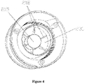
Figure 4 is a second schematic view showing the structure of the cyclone separator. -
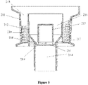
Figure 5 is a sectional view of the cyclone separator. -
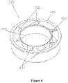
Figure 6 is a schematic view showing the structure of a spiral dust-air separation device. -
Figure 7 is a schematic view showing flowing directions of airflow of the spiral dust-air separation device. -
Figure 8 is a schematic view showing a two-stage dust-air separation. -
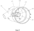
Figure 9 is a schematic view of a cup body. -
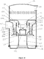
Figure 10 is a sectional view of the dust cup. -
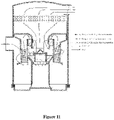
Figure 11 is a view showing flowing directions of airflow in the dust cup. -
Figure 12 is an exploded view of the dust cup. - The names of corresponding components denoted by the reference numerals or letters in the drawings:
100 cup body, 200 two-stage dust-air separation structure, 300 upper cover, 400 sealing ring, 500 base, 110 first-stage dust collecting barrel, 120 air inlet, 130 air outlet, 140 partition plate, 150 opening, 160 return-air dust guard, 170 cyclone rib, 180 air guiding cone, 190 crimping, 111 filter cotton, 210 cyclone separator, 220 spiral dust-air separation device, 211 cyclone housing, 212 second-stage cyclone barrel, 213 air-intake duct, 214 second-stage dust collecting barrel, 215 dust retaining barrel, 216 second-stage dust-air separation duct, 217 conical hole, 218 strip rib, 219 dust retaining flange, 230 filter hole, 231 second-stage dust inlet, 232 spiral groove, 221 spiral impeller, 222 inner ring, 223 outer ring, 224 guidance tangent plane, 225 wind shielding plate. - A conventional two-stage dust-air separation structure requires a lot of components, and relatively many and complicated molds and assembly processes, and the sealing of each of link is difficult to control, thus air leakage and dust leakage phenomena are apt to occur, which adversely affects the comprehensive performance of the whole machine. In addition, a conventional two-stage dust-air separation type dust cup structure is axially arranged, and its filter structure occupies a large portion of the space of the dust cup and occupies too much of the dust collecting volume of the dust cup, and a dust storage space is limited. Moreover, this two-stage dust-air separation dust cup structure requires the dust cup to have a relatively high size and a relatively large volume, thus is not applicable to a mini dust collector and a portable dust collector, and the application scope thereof is limited.
- In view of the deficiencies in the conventional technology, a two-stage dust-air separation structure and a dust cup having the structure are provided according to the present application, to reduce the number of the components, simplify the assembly process, improve the comprehensive performance of the whole machine, and also effectively reduce the space of the dust cup that is occupied by the two-stage separation structure, to realize the maximum dust storage volume and improve the dust collecting efficiency, thereby allowing the two-stage dust-air separation structure to be applicable to dust collectors of various types and sizes.
- Technical solutions of the present application are described clearly and completely with reference to embodiments hereinafter. Apparently, the described embodiments are only a few rather than all of the embodiments of the present application. Other embodiments obtained by the person skilled in the art without any creative efforts based on the embodiments of the present application fall into the scope of the present application.
- Referring to
Figures 3 to 8 , a two-stage dust-air separation structure is provided, which includes acyclone separator 210 and a spiral dust-air separation device 220. Thecyclone separator 210 includes acyclone housing 211 for a first stage dust-air separation and a second-stage cyclone barrel 212 arranged inside thecyclone housing 211. A gap is provided between the second-stage cyclone barrel and an inner wall of the cyclone housing, and the gap is configured to form an air-intake duct 213 for introducing the gas after being separated in the first stage dust-air separation.Filter holes 230 are arranged in the cyclone housing, and after entering from an air inlet, the dusty air firstly passes through thefilter holes 230 to allow large sized debris to be removed and collected in a firststage collecting barrel 110, and the air after going through the first stage separation enters the air-intake duct 213. - A
spiral groove 232 is arranged in an inner side of an upper end of the cyclone housing, such that airflow rotates there and generates a centrifugal force to facilitate airflow's rotating downwards and entering the spiral dust-air separation device. - The spiral dust-
air separation device 220 is arranged at a barrel opening of the second-stage cyclone barrel 212, and an opening connected to a second-stage dust collecting space is further provided at a barrel bottom of the second-stage cyclone barrel 212, and the second-stage dust collecting space is a second-stagedust collecting barrel 214. After the dusty air has gone through the first stage dust-air separation performed by thecyclone housing 211, at least part of the dusty air is guided to the spiral dust-air separation device 220 through the air-intake duct 213, and is guided by the spiral dust-air separation device to form, on an inner wall of the second-stage cyclone barrel 212, an airflow rotating towards the barrel bottom, the dust in the airflow is driven by the centrifugal force to rotate downwardly to the barrel bottom and be collected in the second-stagedust collecting barrel 214, and the air in the rotating airflow is extracted by a negative pressure, thereby realizing the second stage dust-air separation. - The spiral dust-
air separation device 220 includes aspiral impeller 221 configured to generate a second-stage cyclone. Thespiral impeller 221 has multiple downward-inclined vanes, and the vanes can constrain the dusty air to flow obliquely downwards to form a spiral airflow. - The spiral dust-
air separation device 220 further includes aninner ring 222 arranged on an inner periphery of thespiral impeller 221. Several guidance tangent planes are arranged on a side wall, corresponding to an air outlet of thespiral impeller 221, of the inner ring 22. The guidance tangent planes can constrain the dusty air to flow to an outer periphery of the spiral impeller to begin to form a rotating state. An outer ring is arranged at an outer periphery of the spiral impeller. The airflow is guided by the inner ring and the outer ring, which improves the structural strength and stability of the spiral impeller. A wall of the inner ring of the spiral impeller may extend downwards to form awind shielding plate 225. - The
cyclone separator 210 further includes an inverteddust retaining barrel 215 arranged inside the second-stage cyclone barrel 212, a gap is provided between the dust retaining barrel and the second-stage cyclone barrel, and the gap is configured to form a second-stage dust-air separation duct 216. The dusty air rotates spirally in the second-stage dust-air separation duct to generate a centrifugal force, to enable the dust to fall down along the inner wall of the second-stage cyclone barrel. An inner side wall of the dust retaining barrel is configured to constrain the dusty air to rotate in the dust retaining barrel to generate a centrifugal force to resist suction of the negative pressure, thereby realizing an effective separation of dust from air. - A lower part of the second-stage cyclone barrel extends obliquely to the center of the bottom to form a
conical hole 217, to enable the dust to fall into the second-stage dust collecting barrel under the guidance of the conical hole. - A gap is provided between a bottom of the
dust retaining barrel 215 and theconical hole 217, and the bottom of thedust retaining barrel 215 and the conical hole are fixedly connected bymultiple strip ribs 218 to enable the dust to stop rotating at the strip ribs, and facilitate the dust's falling down. The space between the gap and the strip ribs forms a second-stage dust inlet 231, and the dust after going through the second stage dust-air separation falls into the second-stage dust collecting space via the second-stage dust inlet. The number of the strip ribs uniformly arranged surrounding the dust retaining barrel may be one, two, three or more, and the specific number is not limited. - The
conical hole 217 extends to the second-stagedust collecting barrel 214 and partially extends into the inside of the second-stage dust collecting barrel to form adust retaining flange 219 of the second-stage dust collecting barrel, to prevent the dust from flowing back. The dust retaining flange may generally be designed to extend to a position within an inner side of a projection of the dust retaining barrel, to ensure the effectiveness of dust retaining, and the specific extended position is not limited. - The cyclone separator and the spiral dust-air separation device may both have an integrally formed structure. After being formed, the spiral dust-air separation device is directly mounted at the center of the cyclone separator and the assembly is just completed. The specific forming manner is not limited.
- In addition, the two-stage dust-air separation structure may also be integrally formed, and the specific forming and assembling manner is not limited.
- Referring to
Figures 1 and2 andFigures 9 to 12 , a dust cup is provided, which includes acup body 100 and a two-stage dust-air separation structure 200 arranged inside thecup body 100. A space between the cup body and the two-stage dust-air separation structure forms a first-stagedust collecting barrel 110 for collecting large sized debris. Anair inlet 120 and anair outlet 130 are arranged in a sidewall of the cup body, dusty air is guided by the air inlet to the cyclone separator of the two-stage dust-air separation structure, and after the dusty air has gone through a first stage dust-air separation performed by acyclone housing 211, at least part of the dusty air enters the second-stage cyclone barrel 212 through the cyclone housing, to proceed to a second stage dust-air separation. - An overall air-intake area of the spiral impeller is less than an air-outgoing area of the dust cup, to enable the dusty air to have a higher rotation speed in the case that the volume of air is constant, to resist the suction of the negative pressure.
- A
partition plate 140 is arranged inside the cup body, a center of the partition plate extends downward to form anopening 150. A return-air dust guard 160 is provided on the opening and above the spiral impeller, the return-air dust guard is fixedly connected to an edge of the opening byseveral cyclone ribs 170 arranged on a periphery of the return-air dust guard, and the air gone through the second stage dust-air separation is extracted by a negative pressure through gaps between the cyclone ribs. By providing the partition plate to shield an upper end of the cyclone housing, the dusty air after being filtered by the cyclone housing may be guided from an upper end of the air-intake duct into the spiral dust-air separation device, to realize guidance to the ingoing air. A central part of the partition plate has a downward-inclined curved structure, to facilitate guiding the movement of the dusty air. - A central part of the return-
air dust guard 160 protrudes upward to form anair guiding cone 180 to realize guidance to the return air. With the cooperation between the cyclone ribs and the air guiding cone, the dusty air gone through the second stage separation still keeps a high-speed rotating state when passing through the return-air dust guard. - A bottom of the return-air dust guard has a crimping to achieve quick assembling of the return-air dust guard with the dust retaining barrel and realize effective centering.
- A two-stage dust-air separation structure and a dust cup having the structure are provided according to the present application, and the structure includes a cyclone separator and a spiral dust-air separation device. A first stage separation of dust from air is realized by a cyclone housing, and by arranging a second-stage cyclone barrel inside the cyclone housing and arranging the spiral dust-air separation device at a barrel opening of the second-stage cyclone barrel, the dusty air, after going through the first stage separation, is guided by the spiral dust-air separation device to form, on an inner wall of the second-stage cyclone barrel, an airflow rotating towards the barrel bottom, and the dust in the airflow is driven by a centrifugal force to rotate downwardly to the barrel bottom and be collected in a second-stage dust collecting space, and the air in the rotating airflow is extracted by the negative pressure, thereby realizing a second stage separation of dust from air. The two-stage dust-air separation structure only includes the cyclone housing, the second-stage cyclone and the spiral dust-air separation device, hence, the number of components is effectively reduced, and the assembly process is simplified, which facilitates the improvement of the comprehensive performance of the whole machine. Moreover, the structure has a small volume, thus can effectively reduce the space of the dust cup that is occupied by the two separation structure, realize the maximum dust storage volume and improve the dust collecting efficiency, and is applicable to dust collectors of various types and sizes.
- The description of the embodiments herein enables the person skilled in the art to implement or use the present application. Various modifications to the embodiments are apparent to the person skilled in the art, and the general principle defined herein can be implemented in other embodiments without departing from the scope of the present application. Therefore, the present application is not limited to the embodiments described herein, but within the scope of the appended claims.
Claims (9)
- A dust cup, comprising a cup body (100) and a two-stage dust-air separation structure (200) arranged inside the cup body (100), an air inlet (120) and an air outlet (130) are arranged in a sidewall of the cup body (100), wherein,the two-stage dust-air separation structure (200) comprises a cyclone separator (210) and a spiral dust-air separation device (220), wherein the cyclone separator (210) comprises a cyclone housing (211) for a first stage dust-air separation and a second-stage cyclone barrel (212) arranged inside the cyclone housing (211), a space between the cup body (100) and the cyclone housing (211) of the two-stage dust-air separation structure (200) forms a first-stage dust collecting barrel (110), a gap is provided between the second-stage cyclone barrel (212) and an inner wall of the cyclone housing (211), and the gap is configured to form an air-intake duct (213) for introducing dusty air after going through the first stage dust-air separation; the spiral dust-air separation device (220) is arranged at a barrel opening of the second-stage cyclone barrel (212) and comprises a spiral impeller (221) configured to generate a second-stage cyclone, an opening connected to a second-stage dust collecting space is further provided at a barrel bottom of the second-stage cyclone barrel (212);a partition plate (140) is arranged inside the cup body (100), a center of the partition plate (140) extends downward to form an opening (150), a return-air dust guard (160) is arranged on the extended opening (150) and above the spiral impeller (221), the return-air dust guard (160) is fixedly connected to an edge of the opening (150) by a plurality of cyclone ribs (170) arranged on a periphery of the return-air dust guard (160), such that the air after going through the second stage dust-air separation is extracted by the negative pressure via gaps between the cyclone ribs (170), to realize a second stage dust-air separation;wherein, the cyclone separator (210) further comprises:
an inverted dust retaining barrel (215) arranged inside the second-stage cyclone barrel (212), a gap is provided between the dust retaining barrel (215) and the second-stage cyclone barrel (212), and the gap is configured to form a second-stage dust-air separation duct (216). - The dust cup according to claim 1, wherein the spiral impeller (221) has a plurality of downward-inclined vanes, and the vanes are configured to constrain the dusty air to flow obliquely downwards.
- The dust cup according to claim 2, wherein the spiral dust-air separation device (220) further comprises an inner ring (222) arranged on an inner periphery of the spiral impeller (221), a plurality of guidance tangent planes are arranged on a side wall, corresponding to an air outlet of the spiral impeller (221), of the inner ring (222), to constrain the dusty air to flow to an outer periphery of the spiral impeller to begin to form a rotating state.
- The dust cup according to claim 2, wherein a wall of the inner ring (222) of the spiral impeller (221) extends downwards to form a wind shielding plate (225).
- The dust cup according to claim 1, wherein a lower part of the second-stage cyclone barrel extends obliquely to a center of the barrel bottom of the second-stage cyclone barrel to form a conical hole (217).
- The dust cup according to claim 5, wherein a gap is provided between a bottom of the dust retaining barrel (215) and the conical hole (217), and the bottom of the dust retaining barrel (215) and the conical hole (217) are fixedly connected by a plurality of strip ribs (218) to allow the dust to stop rotating at the strip ribs (218), a space between the gap and the strip ribs (218) forms a second-stage dust inlet (231).
- The dust cup according to claim 5, wherein the second-stage dust collecting space is configured as a second-stage dust collecting barrel (214) arranged below the second-stage cyclone barrel (212), the conical hole (217) extends to the second-stage dust collecting barrel (214) and partially extends into an inside of the second-stage dust collecting barrel (214) to form a dust retaining flange of the second-stage dust collecting barrel (214).
- The dust cup according to claim 1, wherein an overall air-intake area of the spiral impeller (221) is less than an air-outgoing area of the dust cup (100), to allow a centrifugal force generated by rotation to be sufficient to resist a suction of the negative pressure.
- The dust cup according to claim 1, wherein a central part of the return-air dust guard (160) protrudes upward to form an air guiding cone (180) for guiding return air.
Applications Claiming Priority (2)
| Application Number | Priority Date | Filing Date | Title |
|---|---|---|---|
| CN201510044589.XA CN104545695B (en) | 2015-01-28 | 2015-01-28 | A kind of two grades of dust and gas isolating constructions and comprise the dirt cup of this structure |
| PCT/CN2015/094096 WO2016119503A1 (en) | 2015-01-28 | 2015-11-09 | Two-stage dust-air separation structure and dust cup comprising same |
Publications (3)
| Publication Number | Publication Date |
|---|---|
| EP3251573A1 EP3251573A1 (en) | 2017-12-06 |
| EP3251573A4 EP3251573A4 (en) | 2018-11-07 |
| EP3251573B1 true EP3251573B1 (en) | 2022-05-04 |
Family
ID=53063574
Family Applications (1)
| Application Number | Title | Priority Date | Filing Date |
|---|---|---|---|
| EP15879701.9A Active EP3251573B1 (en) | 2015-01-28 | 2015-11-09 | Two-stage dust-air separation structure and dust cup comprising same |
Country Status (5)
| Country | Link |
|---|---|
| US (1) | US10406535B2 (en) |
| EP (1) | EP3251573B1 (en) |
| CN (1) | CN104545695B (en) |
| AU (1) | AU2015379894B2 (en) |
| WO (1) | WO2016119503A1 (en) |
Families Citing this family (62)
| Publication number | Priority date | Publication date | Assignee | Title |
|---|---|---|---|---|
| US20140237768A1 (en) | 2013-02-28 | 2014-08-28 | G.B.D. Corp. | Surface cleaning apparatus |
| CN104545695B (en) | 2015-01-28 | 2016-08-31 | 莱克电气股份有限公司 | A kind of two grades of dust and gas isolating constructions and comprise the dirt cup of this structure |
| CN104840152A (en) * | 2015-06-09 | 2015-08-19 | 莱克电气股份有限公司 | Handheld dust collector with spiral two-level tornado dust-air separation structure |
| CN105266718B (en) * | 2015-11-03 | 2018-01-30 | 莱克电气股份有限公司 | A multi-stage tornado cyclone mechanism and dust cup structure |
| CN105249891B (en) | 2015-11-03 | 2018-01-30 | 莱克电气股份有限公司 | A kind of three-level cyclone dirt cup filtration system and the dust catcher comprising the system |
| KR102560970B1 (en) | 2016-03-31 | 2023-07-31 | 엘지전자 주식회사 | Cleaner |
| CN112021988A (en) | 2016-03-31 | 2020-12-04 | Lg电子株式会社 | Vacuum cleaner |
| US11166607B2 (en) | 2016-03-31 | 2021-11-09 | Lg Electronics Inc. | Cleaner |
| USD857071S1 (en) * | 2017-01-24 | 2019-08-20 | Superior Industries, Inc. | Hydrocyclone inlet head |
| USD828422S1 (en) * | 2017-01-24 | 2018-09-11 | Superior Industries, Inc. | Hydrocyclone inlet head |
| CN106422536A (en) * | 2016-11-16 | 2017-02-22 | 上海核工程研究设计院 | Steam-water separator for steam generator |
| CN106861929A (en) * | 2017-02-27 | 2017-06-20 | 潘景良 | External force drives rotation cyclone separator |
| GB2563695B (en) * | 2017-06-19 | 2020-03-11 | Tti Macao Commercial Offshore Ltd | A surface cleaning apparatus |
| CN107755106A (en) * | 2017-09-25 | 2018-03-06 | 浙江德清华丝纺织有限公司 | A kind of air processor for spinning and weaving workshop |
| CN107595204B (en) | 2017-10-31 | 2022-10-25 | 卓力电器集团有限公司 | Two-stage dust-air separation cyclone type dust cup capable of absorbing water and dust collector thereof |
| CN107890321B (en) * | 2017-11-12 | 2023-05-30 | 苏州市凯丽保姆电器有限公司 | Dust collector |
| CN107837036A (en) * | 2017-11-30 | 2018-03-27 | 莱克电气股份有限公司 | Stick vacuums dirt cup filtration system and the stick vacuums using the filtration system |
| US11007541B2 (en) * | 2018-04-23 | 2021-05-18 | X'pole Precision Tools Inc. | Dust collecting device using multi-cyclone dust filtration |
| CN108402991A (en) * | 2018-05-14 | 2018-08-17 | 宁波春仁电器有限公司 | Wet-dry hand held cleaner |
| EP4180111B1 (en) * | 2018-05-18 | 2024-11-13 | Donaldson Company, Inc. | Precleaner arrangement for use in air filtration |
| CN108852172B (en) * | 2018-07-31 | 2023-09-22 | 珠海格力电器股份有限公司 | Spiral dust-gas separation device and gas purification device |
| CN108903802B (en) * | 2018-08-06 | 2023-11-24 | 珠海格力电器股份有限公司 | Cyclone separation device and gas purification device |
| CN109157159A (en) * | 2018-08-29 | 2019-01-08 | 宁波富佳实业有限公司 | Dust catcher with dust separation structure |
| CN108836186A (en) * | 2018-09-11 | 2018-11-20 | 小狗电器互联网科技(北京)股份有限公司 | Dirt cup structure and horizontal dust collector |
| CN109330483B (en) * | 2018-11-16 | 2021-07-16 | 江苏美的清洁电器股份有限公司 | Dust and gas separation components of vacuum cleaners and vacuum cleaners |
| US11351492B2 (en) * | 2019-02-20 | 2022-06-07 | B/E Aerospace, Inc. | Inline vortex demister |
| CN109720879A (en) * | 2019-02-28 | 2019-05-07 | 马鞍山市中天机械制造安装有限公司 | A kind of twin screws formula deashing device |
| CN210810786U (en) * | 2019-04-29 | 2020-06-23 | 拓浦精工智能制造(邵阳)有限公司 | Gas-dust separation device and vacuum cleaner |
| CN110102111B (en) * | 2019-05-08 | 2024-07-16 | 佛山市东山瑞泽环保机器有限公司 | Shrink gas ring type gas-liquid separator |
| CN110037615B (en) * | 2019-05-15 | 2024-08-13 | 宁波普净环保科技有限公司 | A vacuum cleaner with a multi-stage cyclone separation structure and a working method thereof |
| CN110811427B (en) * | 2019-12-09 | 2025-11-28 | 珠海格力电器股份有限公司 | Air duct structure, cleaning equipment and dust collector |
| US11419467B2 (en) * | 2020-01-23 | 2022-08-23 | Oneida Air Systems, Inc. | Bucket lid for auxiliary cyclone dust collector |
| CN112034956A (en) * | 2020-08-26 | 2020-12-04 | 杭州郜灵科技有限公司 | Utilize cyclone centrifugal separation's computer radiator |
| CN114191891B (en) * | 2020-09-02 | 2025-08-22 | 博世电动工具(中国)有限公司 | Power tool and cyclone separation unit thereof |
| CN112220414A (en) * | 2020-10-10 | 2021-01-15 | 深圳市杉川机器人有限公司 | Double-vortex air dust box structure and sweeping robot |
| CN114631752B (en) * | 2020-12-15 | 2023-10-13 | 莱克电气股份有限公司 | Guide parts, dust and gas separation mechanisms and cleaning equipment |
| CN112755708A (en) * | 2020-12-29 | 2021-05-07 | 江苏鹰游纺机有限公司 | Combined type water spraying, cooling and impurity removing device and method |
| CN112890663B (en) * | 2021-02-04 | 2022-04-22 | 广州市亿康环保设备有限公司 | Dust collector |
| CN112933840A (en) * | 2021-02-07 | 2021-06-11 | 华南理工大学 | Self-filming cyclone plate dust and mist eliminator |
| CN112931237A (en) * | 2021-04-14 | 2021-06-11 | 惠康智创环境科技有限公司 | Air conditioner for pigsty |
| CN113634050B (en) * | 2021-08-26 | 2023-04-07 | 广东新氧器净化科技有限公司 | Cyclone collision dust removal pretreatment device |
| CN115721205B (en) * | 2021-08-31 | 2025-08-19 | 莱克电气股份有限公司 | Dust-gas separation piece, gas-liquid separator and cleaning equipment |
| CN114177731B (en) * | 2021-11-10 | 2023-06-30 | 北京城建集团有限责任公司 | Dust collector for building construction |
| CN113893635B (en) * | 2021-11-16 | 2023-07-21 | 江苏精亚环境科技有限公司 | Method and equipment for separating secondary dust and velvet dust of dust filtering unit |
| CN114432795B (en) * | 2021-12-14 | 2022-11-15 | 中氢新能技术有限公司 | Gas-liquid separator for methanol fuel cell tail gas |
| CN114794969A (en) * | 2022-04-11 | 2022-07-29 | 苏州市春菊电器有限公司 | Gradual change structure of dust cup cyclone system and dust collector |
| CN115005709B (en) * | 2022-04-29 | 2024-05-07 | 苏州普沃达智能科技有限公司 | Water-dust separating device for dust collector |
| CN115228225B (en) * | 2022-05-23 | 2023-12-08 | 江苏精亚环境科技有限公司 | Centralized collection and treatment system for textile dust |
| CN115276374B (en) * | 2022-06-30 | 2024-06-28 | 南京鼎恩电子信息有限公司 | Converter of direct current remote power supply |
| CN115970921B (en) * | 2022-12-09 | 2025-07-25 | 济宁盛唐能源有限公司 | Clean thermoelectric cyclone separator |
| CN116037331B (en) * | 2023-03-06 | 2023-06-23 | 常州长登焊材股份有限公司 | Drawing oil circulation system for high-speed winding and drawing machine |
| KR20240156823A (en) * | 2023-04-24 | 2024-10-31 | 엘지전자 주식회사 | Cleaner |
| CN117483123A (en) * | 2023-10-26 | 2024-02-02 | 广东石油化工学院 | A kind of spiral dust removal channel with flow surface contraction based on the principle of cyclone separation |
| CN117548350B (en) * | 2023-11-28 | 2025-12-05 | 江苏威拉里新材料股份有限公司 | A blockage monitoring and alarm device for an air classifier |
| KR20250088256A (en) * | 2023-12-08 | 2025-06-17 | 삼성전자주식회사 | Cleaner |
| WO2025185228A1 (en) | 2024-03-04 | 2025-09-12 | Sharkninja Operating Llc | Handheld surface cleaner |
| DE102024203008A1 (en) * | 2024-03-28 | 2025-10-02 | BSH Hausgeräte GmbH | Separation unit for a suction device with an inclined flow deflection |
| CN118341188B (en) * | 2024-04-08 | 2024-09-20 | 江苏航宇环境科技有限公司 | High-efficient ambient air dust pelletizing system |
| CN118122071B (en) * | 2024-05-08 | 2024-07-05 | 江苏琳杰环境科技有限公司 | Rotary kiln smoke exhausting and filtering device for continuous pre-carbonization of lithium battery anode material |
| CN119290508B (en) * | 2024-12-13 | 2025-03-07 | 中原工学院 | A fire prevention gas concentration detection device for coal mine goaf |
| CN119909460B (en) * | 2025-02-18 | 2025-10-31 | 上海宝嘉净化工程技术有限公司 | A circulating air duct filter and a medium-efficiency air filter |
| CN120346620B (en) * | 2025-06-23 | 2025-08-26 | 宁津禾洁生物科技有限公司 | Furfural gas-slag separation device and separation method thereof |
Family Cites Families (40)
| Publication number | Priority date | Publication date | Assignee | Title |
|---|---|---|---|---|
| US2654351A (en) * | 1949-02-01 | 1953-10-06 | Babcock & Wilcox Co | Fluid separator |
| US2936043A (en) * | 1957-01-09 | 1960-05-10 | Cottrell Res Inc | Cyclonic dust collector |
| US3349548A (en) * | 1964-01-22 | 1967-10-31 | C C Ind | Cyclone separator for separating steam from water |
| US3425192A (en) * | 1966-12-12 | 1969-02-04 | Mitchell Co John E | Vacuum cleaning system |
| US3788282A (en) * | 1968-06-27 | 1974-01-29 | Babcock & Wilcox Co | Vapor-liquid separator |
| US3590558A (en) * | 1968-11-15 | 1971-07-06 | Combustion Eng | Particle-from-fluid separator |
| DE2051310A1 (en) * | 1970-10-20 | 1972-04-27 | Siemens Ag | Device for steam drying in steam generators of nuclear power plants |
| US4486207A (en) * | 1981-06-22 | 1984-12-04 | Atlantic Richfield Company | Apparatus for reducing attrition of particulate matter in a chemical conversion process |
| FR2662619B1 (en) * | 1990-06-05 | 1993-02-05 | Inst Francais Du Petrole | CO-CURRENT CYCLONIC MIXER-SEPARATOR AND ITS APPLICATIONS. |
| US5229014A (en) * | 1991-12-18 | 1993-07-20 | Vortech International, Inc. | High efficiency centrifugal separation apparatus and method using impeller |
| US6440197B1 (en) * | 1999-07-27 | 2002-08-27 | G.B.D. Corp. | Apparatus and method separating particles from a cyclonic fluid flow including an apertured particle separation member within a cyclonic flow region |
| US6228151B1 (en) * | 1999-08-18 | 2001-05-08 | G.B.D. Corp. | Apparatus and method for separating particles from a cyclonic fluid flow |
| NO315788B1 (en) * | 2001-10-18 | 2003-10-27 | Consept As | Vertically oriented separator for removing liquid droplets from a gas stream |
| CN2768901Y (en) * | 2005-03-03 | 2006-04-05 | 泰怡凯电器(苏州)有限公司 | Cyclone separator |
| KR100662635B1 (en) * | 2005-06-14 | 2007-01-02 | 삼성광주전자 주식회사 | Cyclone Dust Collector of Vacuum Cleaner |
| US7935159B2 (en) * | 2005-08-17 | 2011-05-03 | Lg Electronics Inc. | Dust collecting device for vacuum cleaner |
| US7892305B2 (en) * | 2005-08-17 | 2011-02-22 | Lg Electronics Inc. | Dust collecting device for vacuum cleaner |
| DE112006003479T5 (en) * | 2005-12-22 | 2008-12-18 | Royal Appliance Mfg. Co., Glenwillow | Dual stage cyclone vacuum cleaner |
| US7811345B2 (en) * | 2006-03-10 | 2010-10-12 | G.B.D. Corp. | Vacuum cleaner with a removable cyclone array |
| US8142545B2 (en) * | 2006-05-15 | 2012-03-27 | Federal Signal Corporation | Dust separation system for use with mobile equipment |
| AU2007278711A1 (en) * | 2006-07-21 | 2008-01-31 | Wang, Yuedan | The secondary cyclonic dust separating cup of vacuum cleaner |
| US7842113B2 (en) * | 2006-09-20 | 2010-11-30 | Babcock & Wilcox Power Generation Group, Inc. | Extended water level range steam/water conical cyclone separator |
| EP2031078A1 (en) * | 2007-08-29 | 2009-03-04 | Paul Wurth S.A. | Dust catcher for blast furnace gas |
| CN201219871Y (en) * | 2008-06-26 | 2009-04-15 | 罗建元 | Dust separation cup of vacuum cleaner |
| CN201211161Y (en) * | 2008-06-26 | 2009-03-25 | 胡海荣 | Dust cup of dust collector |
| CN201365881Y (en) * | 2009-03-12 | 2009-12-23 | 罗建元 | Second-level dust-separation device of dust-separation cup of dust collector |
| CN201453152U (en) * | 2009-05-14 | 2010-05-12 | 罗建元 | Secondary dust separation device of dust collector |
| KR20110060385A (en) * | 2009-11-30 | 2011-06-08 | 삼성전자주식회사 | Dust collector with vibration damping unit |
| SE536286C2 (en) * | 2011-10-06 | 2013-07-30 | Husqvarna Ab | Dust separator with constant suction power |
| AU2012384559B2 (en) * | 2012-07-06 | 2018-04-19 | Practical Analyzer Solutions Pte. Ltd. | Centrifugal cyclone separator |
| CN103622642A (en) * | 2012-08-28 | 2014-03-12 | 莱克电气股份有限公司 | Dust collector dust cup without suction loss |
| US9273646B2 (en) * | 2012-09-14 | 2016-03-01 | Mann+ Hummel Gmbh | Cyclone separation device |
| CN203263296U (en) * | 2013-05-08 | 2013-11-06 | 江苏美的春花电器股份有限公司 | Cyclone separator, cyclone separating device adopting cyclone separator, and dust collector adopting cyclone separating device |
| KR102054419B1 (en) * | 2013-05-20 | 2020-01-22 | 주식회사 일렉파워전자 | Cyclone vaccum cleaner |
| DE102013015052B4 (en) * | 2013-09-12 | 2015-10-15 | Mann + Hummel Gmbh | Cyclone filter device |
| CN104644057B (en) * | 2013-11-15 | 2018-08-07 | 创科地板护理技术有限公司 | Cyclone type vacuum cleaner and dust separator |
| US9468348B2 (en) * | 2014-03-19 | 2016-10-18 | X'pole Precision Tools Inc. | Cyclone vacuum cleaner and cyclone separation device thereof |
| US9409189B2 (en) * | 2014-03-26 | 2016-08-09 | Yu-Pei Ho | Modular cyclonic separator for separating solid impurities from an airflow |
| CN204427938U (en) * | 2015-01-28 | 2015-07-01 | 莱克电气股份有限公司 | A kind of secondary dirt gas separation structure and comprise the dirt cup of this structure |
| CN104545695B (en) | 2015-01-28 | 2016-08-31 | 莱克电气股份有限公司 | A kind of two grades of dust and gas isolating constructions and comprise the dirt cup of this structure |
-
2015
- 2015-01-28 CN CN201510044589.XA patent/CN104545695B/en active Active
- 2015-11-09 US US15/544,196 patent/US10406535B2/en active Active
- 2015-11-09 AU AU2015379894A patent/AU2015379894B2/en active Active
- 2015-11-09 EP EP15879701.9A patent/EP3251573B1/en active Active
- 2015-11-09 WO PCT/CN2015/094096 patent/WO2016119503A1/en not_active Ceased
Also Published As
| Publication number | Publication date |
|---|---|
| AU2015379894B2 (en) | 2018-08-23 |
| WO2016119503A1 (en) | 2016-08-04 |
| AU2015379894A1 (en) | 2017-07-13 |
| CN104545695B (en) | 2016-08-31 |
| CN104545695A (en) | 2015-04-29 |
| US20170361338A1 (en) | 2017-12-21 |
| EP3251573A4 (en) | 2018-11-07 |
| US10406535B2 (en) | 2019-09-10 |
| EP3251573A1 (en) | 2017-12-06 |
Similar Documents
| Publication | Publication Date | Title |
|---|---|---|
| US10406535B2 (en) | Two-stage dust-air separation structure and dust cup comprising same | |
| US10568479B2 (en) | Handheld dust collector having spiral two-stage tornado dust-air separation structure | |
| CN106388698B (en) | A kind of dirt cup filter and the dust catcher equipped with the filter | |
| EP3372137B1 (en) | Three-tier cyclone dust bin filtration system and vacuum cleaner comprising the system | |
| JP4934702B2 (en) | Dust cup of head type cyclone vacuum cleaner | |
| CN204427938U (en) | A kind of secondary dirt gas separation structure and comprise the dirt cup of this structure | |
| US7815702B2 (en) | Multi cyclone collector | |
| EP2044875A1 (en) | The secondary cyclonic dust separating cup of vacuum cleaner | |
| SG185349A1 (en) | Collecting device and vacuum cleaner having the same | |
| CN204698456U (en) | A kind of hand held cleaner with spiral secondary spout travel fatigue gas separation structure | |
| CN105266718A (en) | A multi-stage tornado cyclone mechanism and dust cup structure | |
| CN112021995A (en) | Dust separator of dust collector | |
| CN109691934B (en) | Cyclone separation device and sweeping robot | |
| CN206543157U (en) | A kind of dirt cup filter and the dust catcher provided with the filter | |
| CN110664318A (en) | Vacuum cleaner, dust cup device and its separation cone | |
| CN105413369A (en) | Filtering device and dedusting equipment with same | |
| CN210749012U (en) | Dust separator of dust collector | |
| CN105996891A (en) | Main machine of dust collector and dust collector | |
| CN212204749U (en) | Cyclone separation device and air conditioner | |
| CN206044523U (en) | The main frame of vacuum cleaner and vacuum cleaner | |
| CN211487018U (en) | Dust separator | |
| CN217852728U (en) | Double-cyclone dust-gas separation system and dust collector | |
| CN105266719A (en) | Multi-stage cyclone vacuum cleaner dust cup structure | |
| CN215605401U (en) | Dust-gas separation assembly and dust collector with same | |
| CN211187049U (en) | Dust separator of dust collector |
Legal Events
| Date | Code | Title | Description |
|---|---|---|---|
| STAA | Information on the status of an ep patent application or granted ep patent |
Free format text: STATUS: THE INTERNATIONAL PUBLICATION HAS BEEN MADE |
|
| PUAI | Public reference made under article 153(3) epc to a published international application that has entered the european phase |
Free format text: ORIGINAL CODE: 0009012 |
|
| STAA | Information on the status of an ep patent application or granted ep patent |
Free format text: STATUS: REQUEST FOR EXAMINATION WAS MADE |
|
| 17P | Request for examination filed |
Effective date: 20170713 |
|
| AK | Designated contracting states |
Kind code of ref document: A1 Designated state(s): AL AT BE BG CH CY CZ DE DK EE ES FI FR GB GR HR HU IE IS IT LI LT LU LV MC MK MT NL NO PL PT RO RS SE SI SK SM TR |
|
| AX | Request for extension of the european patent |
Extension state: BA ME |
|
| DAV | Request for validation of the european patent (deleted) | ||
| DAX | Request for extension of the european patent (deleted) | ||
| A4 | Supplementary search report drawn up and despatched |
Effective date: 20181010 |
|
| RIC1 | Information provided on ipc code assigned before grant |
Ipc: A47L 9/16 20060101AFI20181004BHEP |
|
| GRAP | Despatch of communication of intention to grant a patent |
Free format text: ORIGINAL CODE: EPIDOSNIGR1 |
|
| STAA | Information on the status of an ep patent application or granted ep patent |
Free format text: STATUS: GRANT OF PATENT IS INTENDED |
|
| INTG | Intention to grant announced |
Effective date: 20211122 |
|
| GRAS | Grant fee paid |
Free format text: ORIGINAL CODE: EPIDOSNIGR3 |
|
| GRAA | (expected) grant |
Free format text: ORIGINAL CODE: 0009210 |
|
| STAA | Information on the status of an ep patent application or granted ep patent |
Free format text: STATUS: THE PATENT HAS BEEN GRANTED |
|
| AK | Designated contracting states |
Kind code of ref document: B1 Designated state(s): AL AT BE BG CH CY CZ DE DK EE ES FI FR GB GR HR HU IE IS IT LI LT LU LV MC MK MT NL NO PL PT RO RS SE SI SK SM TR |
|
| REG | Reference to a national code |
Ref country code: GB Ref legal event code: FG4D |
|
| REG | Reference to a national code |
Ref country code: CH Ref legal event code: EP |
|
| REG | Reference to a national code |
Ref country code: AT Ref legal event code: REF Ref document number: 1488130 Country of ref document: AT Kind code of ref document: T Effective date: 20220515 |
|
| REG | Reference to a national code |
Ref country code: DE Ref legal event code: R096 Ref document number: 602015078800 Country of ref document: DE |
|
| REG | Reference to a national code |
Ref country code: IE Ref legal event code: FG4D |
|
| REG | Reference to a national code |
Ref country code: LT Ref legal event code: MG9D |
|
| REG | Reference to a national code |
Ref country code: NL Ref legal event code: MP Effective date: 20220504 |
|
| REG | Reference to a national code |
Ref country code: AT Ref legal event code: MK05 Ref document number: 1488130 Country of ref document: AT Kind code of ref document: T Effective date: 20220504 |
|
| PG25 | Lapsed in a contracting state [announced via postgrant information from national office to epo] |
Ref country code: SE Free format text: LAPSE BECAUSE OF FAILURE TO SUBMIT A TRANSLATION OF THE DESCRIPTION OR TO PAY THE FEE WITHIN THE PRESCRIBED TIME-LIMIT Effective date: 20220504 Ref country code: PT Free format text: LAPSE BECAUSE OF FAILURE TO SUBMIT A TRANSLATION OF THE DESCRIPTION OR TO PAY THE FEE WITHIN THE PRESCRIBED TIME-LIMIT Effective date: 20220905 Ref country code: NO Free format text: LAPSE BECAUSE OF FAILURE TO SUBMIT A TRANSLATION OF THE DESCRIPTION OR TO PAY THE FEE WITHIN THE PRESCRIBED TIME-LIMIT Effective date: 20220804 Ref country code: NL Free format text: LAPSE BECAUSE OF FAILURE TO SUBMIT A TRANSLATION OF THE DESCRIPTION OR TO PAY THE FEE WITHIN THE PRESCRIBED TIME-LIMIT Effective date: 20220504 Ref country code: LT Free format text: LAPSE BECAUSE OF FAILURE TO SUBMIT A TRANSLATION OF THE DESCRIPTION OR TO PAY THE FEE WITHIN THE PRESCRIBED TIME-LIMIT Effective date: 20220504 Ref country code: HR Free format text: LAPSE BECAUSE OF FAILURE TO SUBMIT A TRANSLATION OF THE DESCRIPTION OR TO PAY THE FEE WITHIN THE PRESCRIBED TIME-LIMIT Effective date: 20220504 Ref country code: GR Free format text: LAPSE BECAUSE OF FAILURE TO SUBMIT A TRANSLATION OF THE DESCRIPTION OR TO PAY THE FEE WITHIN THE PRESCRIBED TIME-LIMIT Effective date: 20220805 Ref country code: FI Free format text: LAPSE BECAUSE OF FAILURE TO SUBMIT A TRANSLATION OF THE DESCRIPTION OR TO PAY THE FEE WITHIN THE PRESCRIBED TIME-LIMIT Effective date: 20220504 Ref country code: ES Free format text: LAPSE BECAUSE OF FAILURE TO SUBMIT A TRANSLATION OF THE DESCRIPTION OR TO PAY THE FEE WITHIN THE PRESCRIBED TIME-LIMIT Effective date: 20220504 Ref country code: BG Free format text: LAPSE BECAUSE OF FAILURE TO SUBMIT A TRANSLATION OF THE DESCRIPTION OR TO PAY THE FEE WITHIN THE PRESCRIBED TIME-LIMIT Effective date: 20220804 Ref country code: AT Free format text: LAPSE BECAUSE OF FAILURE TO SUBMIT A TRANSLATION OF THE DESCRIPTION OR TO PAY THE FEE WITHIN THE PRESCRIBED TIME-LIMIT Effective date: 20220504 |
|
| PG25 | Lapsed in a contracting state [announced via postgrant information from national office to epo] |
Ref country code: RS Free format text: LAPSE BECAUSE OF FAILURE TO SUBMIT A TRANSLATION OF THE DESCRIPTION OR TO PAY THE FEE WITHIN THE PRESCRIBED TIME-LIMIT Effective date: 20220504 Ref country code: PL Free format text: LAPSE BECAUSE OF FAILURE TO SUBMIT A TRANSLATION OF THE DESCRIPTION OR TO PAY THE FEE WITHIN THE PRESCRIBED TIME-LIMIT Effective date: 20220504 Ref country code: LV Free format text: LAPSE BECAUSE OF FAILURE TO SUBMIT A TRANSLATION OF THE DESCRIPTION OR TO PAY THE FEE WITHIN THE PRESCRIBED TIME-LIMIT Effective date: 20220504 Ref country code: IS Free format text: LAPSE BECAUSE OF FAILURE TO SUBMIT A TRANSLATION OF THE DESCRIPTION OR TO PAY THE FEE WITHIN THE PRESCRIBED TIME-LIMIT Effective date: 20220904 |
|
| PG25 | Lapsed in a contracting state [announced via postgrant information from national office to epo] |
Ref country code: SM Free format text: LAPSE BECAUSE OF FAILURE TO SUBMIT A TRANSLATION OF THE DESCRIPTION OR TO PAY THE FEE WITHIN THE PRESCRIBED TIME-LIMIT Effective date: 20220504 Ref country code: SK Free format text: LAPSE BECAUSE OF FAILURE TO SUBMIT A TRANSLATION OF THE DESCRIPTION OR TO PAY THE FEE WITHIN THE PRESCRIBED TIME-LIMIT Effective date: 20220504 Ref country code: RO Free format text: LAPSE BECAUSE OF FAILURE TO SUBMIT A TRANSLATION OF THE DESCRIPTION OR TO PAY THE FEE WITHIN THE PRESCRIBED TIME-LIMIT Effective date: 20220504 Ref country code: EE Free format text: LAPSE BECAUSE OF FAILURE TO SUBMIT A TRANSLATION OF THE DESCRIPTION OR TO PAY THE FEE WITHIN THE PRESCRIBED TIME-LIMIT Effective date: 20220504 Ref country code: DK Free format text: LAPSE BECAUSE OF FAILURE TO SUBMIT A TRANSLATION OF THE DESCRIPTION OR TO PAY THE FEE WITHIN THE PRESCRIBED TIME-LIMIT Effective date: 20220504 Ref country code: CZ Free format text: LAPSE BECAUSE OF FAILURE TO SUBMIT A TRANSLATION OF THE DESCRIPTION OR TO PAY THE FEE WITHIN THE PRESCRIBED TIME-LIMIT Effective date: 20220504 |
|
| REG | Reference to a national code |
Ref country code: DE Ref legal event code: R097 Ref document number: 602015078800 Country of ref document: DE |
|
| PLBE | No opposition filed within time limit |
Free format text: ORIGINAL CODE: 0009261 |
|
| STAA | Information on the status of an ep patent application or granted ep patent |
Free format text: STATUS: NO OPPOSITION FILED WITHIN TIME LIMIT |
|
| PG25 | Lapsed in a contracting state [announced via postgrant information from national office to epo] |
Ref country code: AL Free format text: LAPSE BECAUSE OF FAILURE TO SUBMIT A TRANSLATION OF THE DESCRIPTION OR TO PAY THE FEE WITHIN THE PRESCRIBED TIME-LIMIT Effective date: 20220504 |
|
| 26N | No opposition filed |
Effective date: 20230207 |
|
| PG25 | Lapsed in a contracting state [announced via postgrant information from national office to epo] |
Ref country code: SI Free format text: LAPSE BECAUSE OF FAILURE TO SUBMIT A TRANSLATION OF THE DESCRIPTION OR TO PAY THE FEE WITHIN THE PRESCRIBED TIME-LIMIT Effective date: 20220504 |
|
| PG25 | Lapsed in a contracting state [announced via postgrant information from national office to epo] |
Ref country code: MC Free format text: LAPSE BECAUSE OF FAILURE TO SUBMIT A TRANSLATION OF THE DESCRIPTION OR TO PAY THE FEE WITHIN THE PRESCRIBED TIME-LIMIT Effective date: 20220504 |
|
| REG | Reference to a national code |
Ref country code: CH Ref legal event code: PL |
|
| REG | Reference to a national code |
Ref country code: BE Ref legal event code: MM Effective date: 20221130 |
|
| PG25 | Lapsed in a contracting state [announced via postgrant information from national office to epo] |
Ref country code: LI Free format text: LAPSE BECAUSE OF NON-PAYMENT OF DUE FEES Effective date: 20221130 Ref country code: CH Free format text: LAPSE BECAUSE OF NON-PAYMENT OF DUE FEES Effective date: 20221130 |
|
| PG25 | Lapsed in a contracting state [announced via postgrant information from national office to epo] |
Ref country code: LU Free format text: LAPSE BECAUSE OF NON-PAYMENT OF DUE FEES Effective date: 20221109 |
|
| PG25 | Lapsed in a contracting state [announced via postgrant information from national office to epo] |
Ref country code: IE Free format text: LAPSE BECAUSE OF NON-PAYMENT OF DUE FEES Effective date: 20221109 |
|
| PG25 | Lapsed in a contracting state [announced via postgrant information from national office to epo] |
Ref country code: BE Free format text: LAPSE BECAUSE OF NON-PAYMENT OF DUE FEES Effective date: 20221130 |
|
| PG25 | Lapsed in a contracting state [announced via postgrant information from national office to epo] |
Ref country code: IT Free format text: LAPSE BECAUSE OF FAILURE TO SUBMIT A TRANSLATION OF THE DESCRIPTION OR TO PAY THE FEE WITHIN THE PRESCRIBED TIME-LIMIT Effective date: 20220504 |
|
| PG25 | Lapsed in a contracting state [announced via postgrant information from national office to epo] |
Ref country code: HU Free format text: LAPSE BECAUSE OF FAILURE TO SUBMIT A TRANSLATION OF THE DESCRIPTION OR TO PAY THE FEE WITHIN THE PRESCRIBED TIME-LIMIT; INVALID AB INITIO Effective date: 20151109 |
|
| PG25 | Lapsed in a contracting state [announced via postgrant information from national office to epo] |
Ref country code: CY Free format text: LAPSE BECAUSE OF FAILURE TO SUBMIT A TRANSLATION OF THE DESCRIPTION OR TO PAY THE FEE WITHIN THE PRESCRIBED TIME-LIMIT Effective date: 20220504 |
|
| PG25 | Lapsed in a contracting state [announced via postgrant information from national office to epo] |
Ref country code: MK Free format text: LAPSE BECAUSE OF FAILURE TO SUBMIT A TRANSLATION OF THE DESCRIPTION OR TO PAY THE FEE WITHIN THE PRESCRIBED TIME-LIMIT Effective date: 20220504 |
|
| PG25 | Lapsed in a contracting state [announced via postgrant information from national office to epo] |
Ref country code: TR Free format text: LAPSE BECAUSE OF FAILURE TO SUBMIT A TRANSLATION OF THE DESCRIPTION OR TO PAY THE FEE WITHIN THE PRESCRIBED TIME-LIMIT Effective date: 20220504 |
|
| PG25 | Lapsed in a contracting state [announced via postgrant information from national office to epo] |
Ref country code: MT Free format text: LAPSE BECAUSE OF FAILURE TO SUBMIT A TRANSLATION OF THE DESCRIPTION OR TO PAY THE FEE WITHIN THE PRESCRIBED TIME-LIMIT Effective date: 20220504 |
|
| PG25 | Lapsed in a contracting state [announced via postgrant information from national office to epo] |
Ref country code: BG Free format text: LAPSE BECAUSE OF FAILURE TO SUBMIT A TRANSLATION OF THE DESCRIPTION OR TO PAY THE FEE WITHIN THE PRESCRIBED TIME-LIMIT Effective date: 20220504 |
|
| PG25 | Lapsed in a contracting state [announced via postgrant information from national office to epo] |
Ref country code: BG Free format text: LAPSE BECAUSE OF FAILURE TO SUBMIT A TRANSLATION OF THE DESCRIPTION OR TO PAY THE FEE WITHIN THE PRESCRIBED TIME-LIMIT Effective date: 20220504 |
|
| PGFP | Annual fee paid to national office [announced via postgrant information from national office to epo] |
Ref country code: DE Payment date: 20251117 Year of fee payment: 11 |
|
| PGFP | Annual fee paid to national office [announced via postgrant information from national office to epo] |
Ref country code: GB Payment date: 20251126 Year of fee payment: 11 |
|
| PGFP | Annual fee paid to national office [announced via postgrant information from national office to epo] |
Ref country code: FR Payment date: 20251127 Year of fee payment: 11 |