EP3251537B1 - Closure device for a sports footwear - Google Patents
Closure device for a sports footwear Download PDFInfo
- Publication number
- EP3251537B1 EP3251537B1 EP17174040.0A EP17174040A EP3251537B1 EP 3251537 B1 EP3251537 B1 EP 3251537B1 EP 17174040 A EP17174040 A EP 17174040A EP 3251537 B1 EP3251537 B1 EP 3251537B1
- Authority
- EP
- European Patent Office
- Prior art keywords
- stem
- wings
- lever arm
- lever
- closure device
- Prior art date
- Legal status (The legal status is an assumption and is not a legal conclusion. Google has not performed a legal analysis and makes no representation as to the accuracy of the status listed.)
- Active
Links
Images

Classifications
-
- A—HUMAN NECESSITIES
- A43—FOOTWEAR
- A43B—CHARACTERISTIC FEATURES OF FOOTWEAR; PARTS OF FOOTWEAR
- A43B3/00—Footwear characterised by the shape or the use
- A43B3/0036—Footwear characterised by the shape or the use characterised by a special shape or design
- A43B3/0073—Y-shaped
-
- A—HUMAN NECESSITIES
- A43—FOOTWEAR
- A43C—FASTENINGS OR ATTACHMENTS OF FOOTWEAR; LACES IN GENERAL
- A43C11/00—Other fastenings specially adapted for shoes
- A43C11/14—Clamp fastenings, e.g. strap fastenings; Clamp-buckle fastenings; Fastenings with toggle levers
- A43C11/1406—Fastenings with toggle levers; Equipment therefor
-
- A—HUMAN NECESSITIES
- A43—FOOTWEAR
- A43C—FASTENINGS OR ATTACHMENTS OF FOOTWEAR; LACES IN GENERAL
- A43C11/00—Other fastenings specially adapted for shoes
- A43C11/14—Clamp fastenings, e.g. strap fastenings; Clamp-buckle fastenings; Fastenings with toggle levers
- A43C11/1406—Fastenings with toggle levers; Equipment therefor
- A43C11/142—Fastenings with toggle levers with adjustment means provided for on the shoe, e.g. rack
- A43C11/1433—Fastenings with toggle levers with adjustment means provided for on the shoe, e.g. rack characterised by means to decrease required force for the closure movement of the toggle lever
-
- A—HUMAN NECESSITIES
- A43—FOOTWEAR
- A43C—FASTENINGS OR ATTACHMENTS OF FOOTWEAR; LACES IN GENERAL
- A43C11/00—Other fastenings specially adapted for shoes
- A43C11/14—Clamp fastenings, e.g. strap fastenings; Clamp-buckle fastenings; Fastenings with toggle levers
- A43C11/1406—Fastenings with toggle levers; Equipment therefor
- A43C11/146—Fastenings with toggle levers with adjustment means provided for on the strap, e.g. ratchet strap
- A43C11/1466—Fastenings with toggle levers with adjustment means provided for on the strap, e.g. ratchet strap characterised by means to decrease required force for the closure movement of the toggle lever
Definitions
- the present invention relates to a closure device for a sports footwear. More particularly, the present invention relates to a closure device for sports footwear of the kind comprising a substantially rigid outer shell, such as ski boots and the like.
- the present invention further relates to a sports footwear, more particularly of the kind comprising a substantially rigid outer shell, which is provided with one or more above-mentioned closure devices, and to a method of manufacturing a closure device.
- ski boots and other sports footwear provided with a substantially rigid outer shell have a longitudinal opening, allowing to widen said outer shell for letting the user insert his/her foot into the footwear and remove it therefrom, and are provided with a plurality of closure devices which are transversely arranged across said longitudinal opening, by means of which devices it is possible to close the footwear so as to immobilize the user's foot inside the footwear during the sports practice.
- closure devices which comprise a supporting plate, suitable for being rigidly fastened on a first side of the longitudinal opening of the shell, an actuating lever, which is "U"-shaped and is pivotably connected to said supporting plate, and a tensioning member which at a first end is pivotably connected to a middle portion of the actuating lever and at a second end is provided with hooking means for engaging with an anchoring plate (e.g. a rack) which is rigidly fastened on a second, opposite side of said opening of said shell.
- an anchoring plate e.g. a rack
- Such closure device can switch from an open position, in which the hooking means of the tensioning member are disengaged from the anchoring plate and the distance between the two sides of the longitudinal opening of the shell can be varied, to a closed position, in which the hooking means of the tensioning member are firmly constrained to the anchoring plate and the distance between the supporting plate and the anchoring plate - and therefore the distance between the two sides of the longitudinal opening of the shell - is fixed, and vice versa.
- the actuating lever pivots relative to the supporting plate and, while pivoting, draws the tensioning member and the hooking means, which in turn draw the anchoring plate, thus allowing the two sides of the longitudinal opening of the shell to be brought closer to each other.
- Closure devices of the above-mentioned kind are known, for instance from documents EP 659 360 , US 5 586 367 , EP 1 958 539 and EP 1 985 196 .
- the closure devices - namely the actuating levers of said closure devices - give a significant contribution to the overall appearance of a sports footwear, which can represent a relevant element for the user when evaluating his / her purchase.
- actuating levers are made of plastic material and are manufactured by moulding.
- Moulding is a manufacturing technique which utilizes a mould, in which the material (for instance, plastic material) is injected or otherwise introduced for obtaining components having the desired shape and size.
- the material for instance, plastic material
- moulds having predetermined shapes and sizes are used, which moulds therefore allow to manufacture components all having the same shape and the same size.
- the main object of the present invention is to overcome the drawbacks of prior art, by conjugating the possibility of obtaining closure devices with different shapes and sizes and the need of maintaining the manufacturing costs as low as possible.
- Another object of the present invention is to provide a closure device which in any case shows satisfying performances, namely with reference to its handiness and ease of use.
- the closure device of the present invention comprises a supporting plate, an actuating lever pivotably connected to said supporting plate, a tensioning member, which at a first end is pivotably connected to the actuating lever and at a second end is provided with hooking means, and an anchoring member provided with retaining means (for instance made as an anchoring plate having a rack) in which said hooking means can engage.
- Said lever arm is pivotably connected to the supporting plate and the tensioning member is pivotably connected, at one of its ends, to said lever arm, which therefore carries out the technical functions of the lever.
- said ancillary elements give a substantial contribution for determining the overall appearance of the closure lever.
- the lever arm can be obtained by moulding, by using a single mould, always the same, and the ancillary elements can be obtained by technologies other than moulding, with lower costs.
- the lever arm can be made of metal or plastic material.
- the ancillary element can be made of the same material as the lever arm or of a different material and it can preferably be made of a material which can be worked with limited costs, such as a metal.
- the lever arm is "Y"-shaped, with the free ends of the wings pivotably connected to the supporting plate.
- said ancillary elements are made as elements made of metal wire, suitably shaped and rigidly fastened to said lever arm.
- the ancillary element(s) is/are irremovably connected to the lever arm during the manufacturing process.
- the user has the possibility of replacing said ancillary element(s) during the lifespan of the sports footwear, thus modifying the overall appearance of the closure devices without modifying the other components.
- a ski boot 101 is schematically shown.
- said ski boot 101 comprises an inner liner 103 made of substantially soft material and a shell 105 made of substantially rigid material.
- Both said inner liner and said outer shell comprise a lower portion for receiving the user's foot and a cuff for receiving the user's ankle and the lower part of the user's calf (only the lower portion 105a and the cuff 105b of the shell being visible in Figure 1 ).
- the boot 101 further comprises a plurality of closure devices 1 according to the invention, which are arranged along said longitudinal opening and transversely across it.
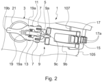
- FIG. 2 a closure device 1 according to the invention is shown in greater detail.
- Said closure device 1 comprises a supporting plate 5 intended to be fastened to the shell 105 of the boot 101, on a first side of the longitudinal opening 107.
- said supporting plate 5 will be provided with through-holes for the passage of corresponding means for fastening to the shell.
- An actuating lever 3 is pivotably connected to the supporting plate 5 by means of rotation pins 7.
- Such device 1 further comprises a tensioning member 9, which has, at a first end thereof, a connecting portion 9a, which portion is articulated to the actuating lever 3 by means of pins 11 with the interposition of an elastic resistance element 13 (such as a spring), and, at a second, opposite end thereof, a hooking portion 9b, said connecting portion and said hooking portion being preferably connected to each other in an articulated way through a swivel joint 9c.
- a tensioning member 9 which has, at a first end thereof, a connecting portion 9a, which portion is articulated to the actuating lever 3 by means of pins 11 with the interposition of an elastic resistance element 13 (such as a spring), and, at a second, opposite end thereof, a hooking portion 9b, said connecting portion and said hooking portion being preferably connected to each other in an articulated way through a swivel joint 9c.
- the hooking portion 9b of the tensioning member 9, at its end farther from the connecting portion 9a, is provided with hooking means 15 which are suitable for engaging with retaining means 17a of an anchoring element - namely an anchoring plate 17 - which is fastened to the shell 105 of the boot 101, on a second, opposite side of the longitudinal opening 107.
- the closure device 1 By acting upon said actuating lever 3 - and more particularly by rotating said lever about the rotation pins 7 - the closure device 1 can be switched from a closed position (shown in Figure 2 ), in which the hooking means 15 of the tensioning member 9 are firmly engaged with the retaining means 17a of the anchoring plate 17, to an open position, in which said hooking means of said tensioning member are disengaged from said retaining means of said anchoring plate 17, and vice versa.
- the actuating lever 3 of the closure device 1 consists of a lever arm 19 and of at least one ancillary element 21 rigidly connected to said lever arm 19.
- both the supporting plate 5 and the tensioning member 9 are connected to the lever arm 19 of the actuating lever 3, so that said lever arm performs the main functional features of said lever.
- the lever arm 19 has a "Y"-like shape and it includes a pair of wings 19a and a stem 19b, which joins the free end of the lever 3 to the bifurcation point of said wings.
- Y-like shape means that the lever arm 19 comprises a first elongated element or stem 19b and two further elongated elements or wings 19a, the stem 19b and the wings 19a lying in a same plane, the wings 19a being parallel to each other and parallel to the stem 19b, and arranged on either sides of said stem 19b, substantially at the same distance therefrom, the wings 19a facing each other and being arranged offset relative to the stem 19b by a distance greater than or equal to the length of the stem 19b and the end of said stem closer to said wings is joined to the ends of said wings closer to said stem through respective joining sections.
- the lever arm 19 can be made of any suitable material according to the knowledge of the person skilled in the art, more particularly of metal or plastic material.
- said lever arm 19 is made of plastic material and is obtained by moulding techniques.
- One or more ancillary elements 21 are rigidly connected to the lever arm 19.
- a single accessory element 21 is provided, which is shaped as a circumference arc, is fastened at its opposite ends to respective wings 19a of the lever arm 19 and passes through the stem 19b of said lever arm, which stem is correspondingly provided with a through-hole.
- the ancillary element 21 is made as an element made of metal wire.
- the material and thickness of said metal wire are selected so that the ancillary element 21 is sufficiently rigid and non-deformable.
- the ancillary element 21 is made of metal wire, it can be obtained with reduced manufacturing costs and it can be shaped in a wide variety of different shapes, as it will be disclosed in detail below.
- the shape and size of the ancillary element 21 can be selected so as to give the actuating lever 3 a high handiness and ease of use and, in particular, to allow to easily grasp said lever: due to the fact that the ancillary element 21 is rigidly connected to the lever arm 19, said ancillary element 21 can be grasped by the user for actuating the rotation of the lever 3, making it switch from the closed position (shown in Figure 2 ) to the open position.
- the ancillary elements 21 can be rigidly connected to the lever arm 19 through any technique within the reach of the person skilled in the art.
- said ancillary elements 21 can be connected to the lever arm 19 either irremovably- for instance by gluing or welding - or removably - for instance by providing, in the body of the lever arm 19, adequate seats in which the ends of said ancillary elements 21 can be removably inserted.
- lever 3 of the closure device 1 comprises a lever arm 19 and one or more separate ancillary elements 21
- a wide variety of closure devices with different appearance can be obtained by starting from the same lever arm 19 and using each time different ancillary elements.
- the amount of plastic material used during the moulding step for the manufacturing of the lever arm 19 is considerably smaller than the amount used for manufacturing the "U"-shaped actuating levers of the conventional closure devices, which involves material and money saving.
- ancillary elements 21 are not involved, or scarcely involved, in the functional features of the lever 3 and the only requirement they have to fulfil is not to be deformed, such ancillary elements can be made of cheaper materials and/or by manufacturing techniques less expensive than moulding.
- the ancillary elements are removably connected to the lever arm, it can be provided that the user can separately purchase different ancillary elements and thus customize his/her sports footwear and/or modify its appearance during its lifespan.
Landscapes
- Footwear And Its Accessory, Manufacturing Method And Apparatuses (AREA)
- Braking Arrangements (AREA)
Description
- The present invention relates to a closure device for a sports footwear. More particularly, the present invention relates to a closure device for sports footwear of the kind comprising a substantially rigid outer shell, such as ski boots and the like.
- The present invention further relates to a sports footwear, more particularly of the kind comprising a substantially rigid outer shell, which is provided with one or more above-mentioned closure devices, and to a method of manufacturing a closure device.
- As is known, ski boots and other sports footwear provided with a substantially rigid outer shell have a longitudinal opening, allowing to widen said outer shell for letting the user insert his/her foot into the footwear and remove it therefrom, and are provided with a plurality of closure devices which are transversely arranged across said longitudinal opening, by means of which devices it is possible to close the footwear so as to immobilize the user's foot inside the footwear during the sports practice.
- More particularly, closure devices are known which comprise a supporting plate, suitable for being rigidly fastened on a first side of the longitudinal opening of the shell, an actuating lever, which is "U"-shaped and is pivotably connected to said supporting plate, and a tensioning member which at a first end is pivotably connected to a middle portion of the actuating lever and at a second end is provided with hooking means for engaging with an anchoring plate (e.g. a rack) which is rigidly fastened on a second, opposite side of said opening of said shell.
- Such closure device can switch from an open position, in which the hooking means of the tensioning member are disengaged from the anchoring plate and the distance between the two sides of the longitudinal opening of the shell can be varied, to a closed position, in which the hooking means of the tensioning member are firmly constrained to the anchoring plate and the distance between the supporting plate and the anchoring plate - and therefore the distance between the two sides of the longitudinal opening of the shell - is fixed, and vice versa. When switching from the open position to the closed position, the actuating lever pivots relative to the supporting plate and, while pivoting, draws the tensioning member and the hooking means, which in turn draw the anchoring plate, thus allowing the two sides of the longitudinal opening of the shell to be brought closer to each other. Closure devices of the above-mentioned kind are known, for instance from documents
EP 659 360 US 5 586 367 ,EP 1 958 539EP 1 985 196 - In general, in known closure devices the actuating levers are made of plastic material and are manufactured by moulding.
- Moulding is a manufacturing technique which utilizes a mould, in which the material (for instance, plastic material) is injected or otherwise introduced for obtaining components having the desired shape and size. In the known moulding processes, moulds having predetermined shapes and sizes are used, which moulds therefore allow to manufacture components all having the same shape and the same size.
- If the manufacturer wished to create a component having a new, different design, he/she should replace the mould, which would involve an important increase of the manufacturing costs due to the production and/or purchase of the new mould.
- In the specific case of the actuating levers of the closure devices for sports footwear, it is evident that the constant manufacturing and/or purchase of new moulds for obtaining components with different shapes and sizes would involve a high costs, which would unsustainably affect the overall manufacturing costs of the sports footwear.
- Accordingly, the main object of the present invention is to overcome the drawbacks of prior art, by conjugating the possibility of obtaining closure devices with different shapes and sizes and the need of maintaining the manufacturing costs as low as possible.
- Another object of the present invention is to provide a closure device which in any case shows satisfying performances, namely with reference to its handiness and ease of use.
- These and other objects are achieved by the closure device for sports footwear as claimed in the appended claims.
- In a manner known per se, the closure device of the present invention comprises a supporting plate, an actuating lever pivotably connected to said supporting plate, a tensioning member, which at a first end is pivotably connected to the actuating lever and at a second end is provided with hooking means, and an anchoring member provided with retaining means (for instance made as an anchoring plate having a rack) in which said hooking means can engage.
- Said closure device can be used as closure device for sports footwear, and it is particularly suitable for being used as closure device for sports footwear of the kind comprising a substantially rigid outer shell (for instance made of rigid plastic material), such as ski boots and the like. According to the invention, the actuating lever of said closure device consists of a lever arm and of one or more ancillary elements rigidly connected to said lever arm, as disclosed by the
independent claim 1. - Said lever arm is pivotably connected to the supporting plate and the tensioning member is pivotably connected, at one of its ends, to said lever arm, which therefore carries out the technical functions of the lever. On the other hand, said ancillary elements give a substantial contribution for determining the overall appearance of the closure lever.
- Due to the fact that the functional features and the aesthetical features of the lever of the closure device according to the invention are largely independent from each other, a high versatility can be obtained.
- More particularly, it is possible to envisage a plurality of closure devices in which the lever arm is invariant in shape and the ancillary element(s) rigidly fastened to said lever arm is/are different each time, which allows to obtain a plurality of products having significantly different aesthetical features with low manufacturing costs.
- More particularly, the lever arm can be obtained by moulding, by using a single mould, always the same, and the ancillary elements can be obtained by technologies other than moulding, with lower costs. The lever arm can be made of metal or plastic material. The ancillary element can be made of the same material as the lever arm or of a different material and it can preferably be made of a material which can be worked with limited costs, such as a metal.
- According to the claimed invention, the lever arm is "Y"-shaped, with the free ends of the wings pivotably connected to the supporting plate.
- Advantageously, if compared to conventional "U"-shaped lever arms, the "Y"-like shape of the present invention allows remarkable saving of the used material, which contributes to keep the overall manufacturing costs low.
- Still according to said preferred embodiment of the invention, said ancillary elements are made as elements made of metal wire, suitably shaped and rigidly fastened to said lever arm.
- Due to the fact that the ancillary elements are made as elements made of metal wire, the manufacturing costs can be further reduced.
- Moreover, by using elements made of metal wire, the ancillary elements can be shaped with such a shape and size that a great handiness can be conferred to the actuating lever of the closure device, which lever can be grasped with high ease of use during the opening and closing operations of the device itself, even in uncomfortable situations, such as while wearing gloves or in the presence of snow and ice.
- In an embodiment of the invention, the ancillary element(s) is/are irremovably connected to the lever arm during the manufacturing process.
- In an alternative embodiment of the invention, the ancillary element(s) is/are removably fastened to the lever arm during the manufacturing process.
- Advantageously, according to this particular embodiment the user has the possibility of replacing said ancillary element(s) during the lifespan of the sports footwear, thus modifying the overall appearance of the closure devices without modifying the other components.
- Further features and advantages of the invention will become more evident from a detailed description of a preferred embodiment of the invention itself, given by way of non-limiting example with reference to the attached drawings, in which:
-
Figure 1 shows a sports footwear provided with a plurality of closure devices according to the invention; -
Figure 2 shows in greater detail a closure device according to the invention; -
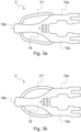
Figures 3a e3b show two possible manufacturing variants of the lever of the closure device ofFigure 2 . - With reference initially to
Figure 1 , aski boot 101 is schematically shown. In general saidski boot 101 comprises aninner liner 103 made of substantially soft material and ashell 105 made of substantially rigid material. Both said inner liner and said outer shell comprise a lower portion for receiving the user's foot and a cuff for receiving the user's ankle and the lower part of the user's calf (only thelower portion 105a and thecuff 105b of the shell being visible inFigure 1 ). - The
outer shell 105 comprises alongitudinal opening 107 extending along saidlower portion 105a and saidcuff 105b. Thanks to the presence of said longitudinal opening, the inner volume defined inside theouter shell 105 can be varied. - The
boot 101 further comprises a plurality ofclosure devices 1 according to the invention, which are arranged along said longitudinal opening and transversely across it. - In
Figure 2 aclosure device 1 according to the invention is shown in greater detail. - Said
closure device 1 comprises a supportingplate 5 intended to be fastened to theshell 105 of theboot 101, on a first side of thelongitudinal opening 107. To this aim, said supportingplate 5 will be provided with through-holes for the passage of corresponding means for fastening to the shell. - An actuating
lever 3 is pivotably connected to the supportingplate 5 by means ofrotation pins 7. -
Such device 1 further comprises atensioning member 9, which has, at a first end thereof, a connectingportion 9a, which portion is articulated to the actuatinglever 3 by means ofpins 11 with the interposition of an elastic resistance element 13 (such as a spring), and, at a second, opposite end thereof, a hookingportion 9b, said connecting portion and said hooking portion being preferably connected to each other in an articulated way through aswivel joint 9c. - The hooking
portion 9b of thetensioning member 9, at its end farther from the connectingportion 9a, is provided withhooking means 15 which are suitable for engaging withretaining means 17a of an anchoring element - namely an anchoring plate 17 - which is fastened to theshell 105 of theboot 101, on a second, opposite side of thelongitudinal opening 107. - By acting upon said actuating lever 3 - and more particularly by rotating said lever about the rotation pins 7 - the
closure device 1 can be switched from a closed position (shown inFigure 2 ), in which thehooking means 15 of the tensioningmember 9 are firmly engaged with the retainingmeans 17a of theanchoring plate 17, to an open position, in which said hooking means of said tensioning member are disengaged from said retaining means of said anchoringplate 17, and vice versa. - According to the invention, the actuating
lever 3 of theclosure device 1 consists of alever arm 19 and of at least oneancillary element 21 rigidly connected to saidlever arm 19. - As can be seen in
Figure 1 , both the supportingplate 5 and thetensioning member 9 are connected to thelever arm 19 of theactuating lever 3, so that said lever arm performs the main functional features of said lever. - In the illustrated example, the
lever arm 19 has a "Y"-like shape and it includes a pair ofwings 19a and astem 19b, which joins the free end of thelever 3 to the bifurcation point of said wings. - Herein, "Y"-like shape means that the
lever arm 19 comprises a first elongated element orstem 19b and two further elongated elements orwings 19a, thestem 19b and thewings 19a lying in a same plane, thewings 19a being parallel to each other and parallel to thestem 19b, and arranged on either sides ofsaid stem 19b, substantially at the same distance therefrom, thewings 19a facing each other and being arranged offset relative to thestem 19b by a distance greater than or equal to the length of thestem 19b and the end of said stem closer to said wings is joined to the ends of said wings closer to said stem through respective joining sections. - The end of said
stem 19b opposite to the end joined to thewings 19a is the above-mentioned free end of thelever 3. - The
wings 19a of thelever arm 19 comprise, at their free ends (opposite to the ends joined to thestem 19b), respective bores for connectingpins 7 for the connection to the supportingplate 5, and said wings further comprise, at a middle portion thereof, respective bores for the passage of thepins 11 for the connection to thetensioning member 9. - The
lever arm 19 can be made of any suitable material according to the knowledge of the person skilled in the art, more particularly of metal or plastic material. Preferably, saidlever arm 19 is made of plastic material and is obtained by moulding techniques. - One or more
ancillary elements 21 are rigidly connected to thelever arm 19. - In the example shown in
Figure 2 , asingle accessory element 21 is provided, which is shaped as a circumference arc, is fastened at its opposite ends torespective wings 19a of thelever arm 19 and passes through thestem 19b of said lever arm, which stem is correspondingly provided with a through-hole. - Still with reference to
Figure 2 , it is evident that it could also be possible to provide two distinctancillary elements 21, both having the shape of a circumference arc and fastened at one of their ends to thestem 19b of thelever arm 19 and at the other one of their ends to arespective wing 19a of said lever arm. - According to the illustrated preferred embodiment, the
ancillary element 21 is made as an element made of metal wire. The material and thickness of said metal wire are selected so that theancillary element 21 is sufficiently rigid and non-deformable. - Advantageously, thanks to the fact that the
ancillary element 21 is made of metal wire, it can be obtained with reduced manufacturing costs and it can be shaped in a wide variety of different shapes, as it will be disclosed in detail below. - Advantageously, as can be seen in
Figure 2 , the shape and size of theancillary element 21 can be selected so as to give the actuating lever 3 a high handiness and ease of use and, in particular, to allow to easily grasp said lever: due to the fact that theancillary element 21 is rigidly connected to thelever arm 19, saidancillary element 21 can be grasped by the user for actuating the rotation of thelever 3, making it switch from the closed position (shown inFigure 2 ) to the open position. - The
ancillary elements 21 can be rigidly connected to thelever arm 19 through any technique within the reach of the person skilled in the art. - More particularly, said
ancillary elements 21 can be connected to thelever arm 19 either irremovably- for instance by gluing or welding - or removably - for instance by providing, in the body of thelever arm 19, adequate seats in which the ends of saidancillary elements 21 can be removably inserted. - The advantages of the invention will be immediately evident to the person skilled in the art.
- First of all, thanks to the fact that the
lever 3 of theclosure device 1 comprises alever arm 19 and one or more separateancillary elements 21, a wide variety of closure devices with different appearance can be obtained by starting from thesame lever arm 19 and using each time different ancillary elements. - More particularly, if the
lever arm 19 is made as a moulded piece of plastic material and theancillary elements 21 are made as elements made of metal wire, a wide variety of closure devices with different appearance can be obtained without the need for modifying said mould or using different moulds. - In this respect, two possible manufacturing variants of the
lever 3 of theclosure device 1 are shown inFigures 3a and 3b , which variants only differ in theancillary elements 21', 21" used, thelever arm 19 being unchanged and equal to that of the lever ofFigure 2 . - As can be seen from
Figures 3a and 3b , the overall appearance of the actuating lever 3 - and, as a consequence, of theclosure device 1 and, in turn, of the sports footwear 101 - can be significantly changed by using, instead of theancillary elements 21 shaped as circumference arcs ofFigure 2 , ancillary elements 21' shaped as a broken line (Figure 3a ) orancillary elements 21" shaped as an ellipse arc (Figure 3b ). - Secondly, the amount of plastic material used during the moulding step for the manufacturing of the
lever arm 19 only is considerably smaller than the amount used for manufacturing the "U"-shaped actuating levers of the conventional closure devices, which involves material and money saving. - Thirdly, since the
ancillary elements 21 are not involved, or scarcely involved, in the functional features of thelever 3 and the only requirement they have to fulfil is not to be deformed, such ancillary elements can be made of cheaper materials and/or by manufacturing techniques less expensive than moulding. - Moreover, by using different materials and manufacturing techniques it is possible to obtain shapes that could hardly be obtained by moulding. More particularly, it is possible to manufacture ancillary elements which improve the handiness and the ease of grasping of the actuating lever of the closure device with respect to the known devices.
- Fourthly, if the ancillary elements are removably connected to the lever arm, it can be provided that the user can separately purchase different ancillary elements and thus customize his/her sports footwear and/or modify its appearance during its lifespan.
Claims (10)
- Closure device (1) comprising a supporting plate (5), an actuating lever (3) pivotably connected to said supporting plate (5), a tensioning member (9) connected at one of its ends to said lever (3) and provided at its opposite end with hooking means (15), and an anchoring member (17) provided with retaining means (17a), wherein said hooking means (15) of said tensioning member are intended to selectively engage said retaining means (17a) of said anchoring member, wherein said actuating lever (3) consists of a lever arm (19) and of at least one or more ancillary elements (21; 21'; 21") rigidly connected to said lever arm (19) and said supporting plate (5) and said tensioning member (9) are connected to said actuating lever (3) at said lever arm (19), characterized in that said lever arm (19) has a "Y"-like shape and comprises a pair of wings (19a), having respective free ends, and a stem (19b), extending from the bifurcation point of said wings opposite to said free ends, said stem (19b) being made as a first elongated element or stem and said wings (19a) being made as two further elongated elements, said stem (19b) and said wings (19a) lying in a same plane, said wings (19a) being parallel to each other and parallel to said stem (19b), and arranged on either sides of said stem (19b), substantially at the same distance therefrom, said wings (19a) facing each other and being arranged offset relative to the stem (19b) by a distance greater than or equal to the length of the stem (19b) and the end of said stem closer to said wings being joined to the ends of said wings closer to said stem through respective joining sections, and in that said supporting plate (5) is connected to said actuating lever (3) at the free ends of said wings (19a) of said lever arm (19) and said tensioning member (9) is connected to said actuating lever (3) at a middle portion of said wings (19a) of said lever arm (19).
- Closure device (1) according to claim 1, wherein a single ancillary element (21; 21'; 21") is provided, which ancillary element (21; 21'; 21") is fastened at its opposite ends to respective wings (19a) of said lever arm (19) and passes through said stem (19b) of said lever arm (19).
- Closure device (1) according to claim 1, wherein a pair of ancillary elements are provided, each of said ancillary elements being fastened at one of its ends to said stem (19b) of said lever arm (19) and at its opposite end to a respective wing (19a) of said lever arm (19).
- Closure device (1) according to any of the claims 1 - 3, wherein said lever arm (19) is made of metal or plastic material.
- Closure device (1) according to any of the claims 1 - 4, wherein said one or more ancillary elements (21; 21'; 21") are elements made of metal wire.
- Closure device (1) according to any of the claims 1 - 5, wherein said one or more ancillary elements (21; 21'; 21") are irremovably fastened to said lever arm (19).
- Closure device (1) according to any of the claims 1 - 5, wherein said one or more ancillary elements (21; 21'; 21") are removably fastened to said lever arm (19).
- Sports footwear (101), of the kind comprising an outer shell (105) made of a substantially rigid material and provided with a longitudinal opening (107) that extends along said shell, characterized in that it comprises one or more closure devices according to any of the claims 1-7 arranged transversely across said longitudinal opening (107), said supporting plate (5) and said anchoring member (17) being fastened to said shell on the opposite sides of said longitudinal opening (107).
- Method for manufacturing a closure device (1), of the kind comprising a supporting plate (5), an actuating lever (3) pivotably connected to said supporting plate (5), a tensioning member (9) connected at one of its ends to said lever (3) and provided at its opposite end with hooking means (15), and an anchoring member (17) provided with retaining means (17a), characterized in that it comprises the steps of:- moulding a lever arm (19), said lever arm (19) having a "Y"-like shape and comprising a pair of wings (19a), having respective free ends, and a stem (19b), extending from the bifurcation point of said wings opposite to said free ends, said stem (19b) being made as a first elongated element or stem and said wings (19a) being made as two further elongated elements, said stem (19b) and said wings (19a) lying in a same plane, said wings (19a) being parallel to each other and parallel to said stem (19b), and arranged on either sides of said stem (19b), substantially at the same distance therefrom, said wings (19a) facing each other and being arranged offset relative to the stem (19b) by a distance greater than or equal to the length of the stem (19b) and the end of said stem closer to said wings being joined to the ends of said wings closer to said stem through respective joining sections;- shaping one or more ancillary elements (21, 21'; 21"); and- rigidly fastening said one or more ancillary elements (21, 21'; 21") to said lever arm (19) for obtaining said actuating lever (3).
- Method according claim 9, wherein said one or more ancillary elements (21; 21'; 21") are made as elements made of metal wire.
Applications Claiming Priority (1)
| Application Number | Priority Date | Filing Date | Title |
|---|---|---|---|
| ITUA2016A004063A ITUA20164063A1 (en) | 2016-06-01 | 2016-06-01 | Closing device for a sports shoe |
Publications (2)
| Publication Number | Publication Date |
|---|---|
| EP3251537A1 EP3251537A1 (en) | 2017-12-06 |
| EP3251537B1 true EP3251537B1 (en) | 2023-03-08 |
Family
ID=57133289
Family Applications (1)
| Application Number | Title | Priority Date | Filing Date |
|---|---|---|---|
| EP17174040.0A Active EP3251537B1 (en) | 2016-06-01 | 2017-06-01 | Closure device for a sports footwear |
Country Status (2)
| Country | Link |
|---|---|
| EP (1) | EP3251537B1 (en) |
| IT (1) | ITUA20164063A1 (en) |
Family Cites Families (9)
| Publication number | Priority date | Publication date | Assignee | Title |
|---|---|---|---|---|
| FR82548E (en) * | 1962-06-08 | 1964-02-28 | Manufactures Francaises De Bou | Shoe closure device |
| FR1374134A (en) * | 1962-11-13 | 1964-10-02 | Quick lever closure device, especially for ski boots | |
| US5526555A (en) | 1993-12-21 | 1996-06-18 | Nordica S.P.A | Fastening device, particularly for sports shoes |
| FR2726161B1 (en) | 1994-11-02 | 1997-04-04 | Salomon Sa | HOOK CLOSURE FOR FOOTWEAR |
| IT1298824B1 (en) * | 1998-03-27 | 2000-02-02 | Htm Sport Spa | LEVER STRUCTURE, ESPECIALLY FOR SPORTS FOOTWEAR |
| ITTV20060208A1 (en) * | 2006-11-16 | 2008-05-17 | Premec Spa | LEVER ARM STRUCTURE, PARTICULARLY FOR SPORTS SHOES |
| DE102007007954B3 (en) | 2007-02-17 | 2008-02-07 | Hetal-Werke Franz Hettich Gmbh & Co. Kg | Corner cupboard i.e. fitted-kitchen corner cupboard, has actuating device with actuator e.g. electrical actuator, that is activated by activating unit, where actuator moves door to opening position during activation |
| FR2915353B1 (en) * | 2007-04-27 | 2009-07-17 | Salomon Sa | CLOSURE HOOK OF A SHOE |
| IT1392425B1 (en) * | 2008-12-23 | 2012-03-02 | Baggio | CLOSING DEVICE, PARTICULARLY FOR SPORTS SHOES. |
-
2016
- 2016-06-01 IT ITUA2016A004063A patent/ITUA20164063A1/en unknown
-
2017
- 2017-06-01 EP EP17174040.0A patent/EP3251537B1/en active Active
Also Published As
| Publication number | Publication date |
|---|---|
| ITUA20164063A1 (en) | 2017-12-01 |
| EP3251537A1 (en) | 2017-12-06 |
Similar Documents
| Publication | Publication Date | Title |
|---|---|---|
| US20070192998A1 (en) | Pant cuff retaining clip assemblies | |
| US8341763B2 (en) | Reinforcing element | |
| EP3624626B1 (en) | Shoe | |
| NO330832B1 (en) | A fastening device | |
| EP2591696B1 (en) | Closing device for a sports footwear such as a ski boot, snowboard boot or suchlike | |
| JP2768643B2 (en) | Snowboard boots | |
| CA2718776A1 (en) | Garment opener/closer and fastener | |
| US20050022428A1 (en) | Shoe fastening and closure device and method of using same | |
| CN106535684A (en) | Molded watersports and cold climate accessories | |
| EP3251537A1 (en) | Closure device for a sports footwear | |
| AU2019222132B2 (en) | Sandal having releasable strap fastening | |
| JP4812638B2 (en) | Glove reinforcement member | |
| EP1997397A1 (en) | A fastening system for fastening a mountaineering boot to a mountaineering ski | |
| US9743708B2 (en) | Sports boot | |
| EP3175731A1 (en) | Ski boot | |
| FR2499834A1 (en) | LOW SPORTS SHOE ESPECIALLY FOR CROSS-COUNTRY SKIING | |
| EP2818069B1 (en) | Sport footwear, such as a ski boot or similar | |
| EP3028592B1 (en) | Ski boot or off-track ski boot with perfected fastening means | |
| EP2082657A1 (en) | Sports boot such as a ski boot or suchlike | |
| EP3354148B1 (en) | Closure device for a sports footwear provided with an improved actuating lever | |
| EP4188146B1 (en) | Accessory for flip flop sandal and sandal provided with such an accessory | |
| US9149140B1 (en) | Ski boot removal tool and method of use | |
| US214231A (en) | Improvement in ankle-supports for skates | |
| CN203252052U (en) | Shoe | |
| CN103054274B (en) | a kind of shoe |
Legal Events
| Date | Code | Title | Description |
|---|---|---|---|
| PUAI | Public reference made under article 153(3) epc to a published international application that has entered the european phase |
Free format text: ORIGINAL CODE: 0009012 |
|
| STAA | Information on the status of an ep patent application or granted ep patent |
Free format text: STATUS: THE APPLICATION HAS BEEN PUBLISHED |
|
| AK | Designated contracting states |
Kind code of ref document: A1 Designated state(s): AL AT BE BG CH CY CZ DE DK EE ES FI FR GB GR HR HU IE IS IT LI LT LU LV MC MK MT NL NO PL PT RO RS SE SI SK SM TR |
|
| AX | Request for extension of the european patent |
Extension state: BA ME |
|
| STAA | Information on the status of an ep patent application or granted ep patent |
Free format text: STATUS: REQUEST FOR EXAMINATION WAS MADE |
|
| 17P | Request for examination filed |
Effective date: 20180427 |
|
| RBV | Designated contracting states (corrected) |
Designated state(s): AL AT BE BG CH CY CZ DE DK EE ES FI FR GB GR HR HU IE IS IT LI LT LU LV MC MK MT NL NO PL PT RO RS SE SI SK SM TR |
|
| STAA | Information on the status of an ep patent application or granted ep patent |
Free format text: STATUS: EXAMINATION IS IN PROGRESS |
|
| 17Q | First examination report despatched |
Effective date: 20220328 |
|
| GRAP | Despatch of communication of intention to grant a patent |
Free format text: ORIGINAL CODE: EPIDOSNIGR1 |
|
| STAA | Information on the status of an ep patent application or granted ep patent |
Free format text: STATUS: GRANT OF PATENT IS INTENDED |
|
| INTG | Intention to grant announced |
Effective date: 20221006 |
|
| GRAS | Grant fee paid |
Free format text: ORIGINAL CODE: EPIDOSNIGR3 |
|
| GRAA | (expected) grant |
Free format text: ORIGINAL CODE: 0009210 |
|
| STAA | Information on the status of an ep patent application or granted ep patent |
Free format text: STATUS: THE PATENT HAS BEEN GRANTED |
|
| AK | Designated contracting states |
Kind code of ref document: B1 Designated state(s): AL AT BE BG CH CY CZ DE DK EE ES FI FR GB GR HR HU IE IS IT LI LT LU LV MC MK MT NL NO PL PT RO RS SE SI SK SM TR |
|
| REG | Reference to a national code |
Ref country code: GB Ref legal event code: FG4D |
|
| REG | Reference to a national code |
Ref country code: CH Ref legal event code: EP Ref country code: AT Ref legal event code: REF Ref document number: 1551981 Country of ref document: AT Kind code of ref document: T Effective date: 20230315 |
|
| REG | Reference to a national code |
Ref country code: DE Ref legal event code: R096 Ref document number: 602017066561 Country of ref document: DE |
|
| REG | Reference to a national code |
Ref country code: IE Ref legal event code: FG4D |
|
| REG | Reference to a national code |
Ref country code: LT Ref legal event code: MG9D |
|
| REG | Reference to a national code |
Ref country code: NL Ref legal event code: MP Effective date: 20230308 |
|
| PG25 | Lapsed in a contracting state [announced via postgrant information from national office to epo] |
Ref country code: RS Free format text: LAPSE BECAUSE OF FAILURE TO SUBMIT A TRANSLATION OF THE DESCRIPTION OR TO PAY THE FEE WITHIN THE PRESCRIBED TIME-LIMIT Effective date: 20230308 Ref country code: NO Free format text: LAPSE BECAUSE OF FAILURE TO SUBMIT A TRANSLATION OF THE DESCRIPTION OR TO PAY THE FEE WITHIN THE PRESCRIBED TIME-LIMIT Effective date: 20230608 Ref country code: LV Free format text: LAPSE BECAUSE OF FAILURE TO SUBMIT A TRANSLATION OF THE DESCRIPTION OR TO PAY THE FEE WITHIN THE PRESCRIBED TIME-LIMIT Effective date: 20230308 Ref country code: LT Free format text: LAPSE BECAUSE OF FAILURE TO SUBMIT A TRANSLATION OF THE DESCRIPTION OR TO PAY THE FEE WITHIN THE PRESCRIBED TIME-LIMIT Effective date: 20230308 Ref country code: HR Free format text: LAPSE BECAUSE OF FAILURE TO SUBMIT A TRANSLATION OF THE DESCRIPTION OR TO PAY THE FEE WITHIN THE PRESCRIBED TIME-LIMIT Effective date: 20230308 Ref country code: ES Free format text: LAPSE BECAUSE OF FAILURE TO SUBMIT A TRANSLATION OF THE DESCRIPTION OR TO PAY THE FEE WITHIN THE PRESCRIBED TIME-LIMIT Effective date: 20230308 |
|
| REG | Reference to a national code |
Ref country code: AT Ref legal event code: MK05 Ref document number: 1551981 Country of ref document: AT Kind code of ref document: T Effective date: 20230308 |
|
| PG25 | Lapsed in a contracting state [announced via postgrant information from national office to epo] |
Ref country code: SE Free format text: LAPSE BECAUSE OF FAILURE TO SUBMIT A TRANSLATION OF THE DESCRIPTION OR TO PAY THE FEE WITHIN THE PRESCRIBED TIME-LIMIT Effective date: 20230308 Ref country code: NL Free format text: LAPSE BECAUSE OF FAILURE TO SUBMIT A TRANSLATION OF THE DESCRIPTION OR TO PAY THE FEE WITHIN THE PRESCRIBED TIME-LIMIT Effective date: 20230308 Ref country code: GR Free format text: LAPSE BECAUSE OF FAILURE TO SUBMIT A TRANSLATION OF THE DESCRIPTION OR TO PAY THE FEE WITHIN THE PRESCRIBED TIME-LIMIT Effective date: 20230609 Ref country code: FI Free format text: LAPSE BECAUSE OF FAILURE TO SUBMIT A TRANSLATION OF THE DESCRIPTION OR TO PAY THE FEE WITHIN THE PRESCRIBED TIME-LIMIT Effective date: 20230308 |
|
| PG25 | Lapsed in a contracting state [announced via postgrant information from national office to epo] |
Ref country code: SM Free format text: LAPSE BECAUSE OF FAILURE TO SUBMIT A TRANSLATION OF THE DESCRIPTION OR TO PAY THE FEE WITHIN THE PRESCRIBED TIME-LIMIT Effective date: 20230308 Ref country code: RO Free format text: LAPSE BECAUSE OF FAILURE TO SUBMIT A TRANSLATION OF THE DESCRIPTION OR TO PAY THE FEE WITHIN THE PRESCRIBED TIME-LIMIT Effective date: 20230308 Ref country code: PT Free format text: LAPSE BECAUSE OF FAILURE TO SUBMIT A TRANSLATION OF THE DESCRIPTION OR TO PAY THE FEE WITHIN THE PRESCRIBED TIME-LIMIT Effective date: 20230710 Ref country code: EE Free format text: LAPSE BECAUSE OF FAILURE TO SUBMIT A TRANSLATION OF THE DESCRIPTION OR TO PAY THE FEE WITHIN THE PRESCRIBED TIME-LIMIT Effective date: 20230308 Ref country code: CZ Free format text: LAPSE BECAUSE OF FAILURE TO SUBMIT A TRANSLATION OF THE DESCRIPTION OR TO PAY THE FEE WITHIN THE PRESCRIBED TIME-LIMIT Effective date: 20230308 Ref country code: AT Free format text: LAPSE BECAUSE OF FAILURE TO SUBMIT A TRANSLATION OF THE DESCRIPTION OR TO PAY THE FEE WITHIN THE PRESCRIBED TIME-LIMIT Effective date: 20230308 |
|
| PG25 | Lapsed in a contracting state [announced via postgrant information from national office to epo] |
Ref country code: SK Free format text: LAPSE BECAUSE OF FAILURE TO SUBMIT A TRANSLATION OF THE DESCRIPTION OR TO PAY THE FEE WITHIN THE PRESCRIBED TIME-LIMIT Effective date: 20230308 Ref country code: PL Free format text: LAPSE BECAUSE OF FAILURE TO SUBMIT A TRANSLATION OF THE DESCRIPTION OR TO PAY THE FEE WITHIN THE PRESCRIBED TIME-LIMIT Effective date: 20230308 Ref country code: IS Free format text: LAPSE BECAUSE OF FAILURE TO SUBMIT A TRANSLATION OF THE DESCRIPTION OR TO PAY THE FEE WITHIN THE PRESCRIBED TIME-LIMIT Effective date: 20230708 |
|
| REG | Reference to a national code |
Ref country code: DE Ref legal event code: R097 Ref document number: 602017066561 Country of ref document: DE |
|
| PLBE | No opposition filed within time limit |
Free format text: ORIGINAL CODE: 0009261 |
|
| STAA | Information on the status of an ep patent application or granted ep patent |
Free format text: STATUS: NO OPPOSITION FILED WITHIN TIME LIMIT |
|
| PG25 | Lapsed in a contracting state [announced via postgrant information from national office to epo] |
Ref country code: MC Free format text: LAPSE BECAUSE OF FAILURE TO SUBMIT A TRANSLATION OF THE DESCRIPTION OR TO PAY THE FEE WITHIN THE PRESCRIBED TIME-LIMIT Effective date: 20230308 |
|
| PG25 | Lapsed in a contracting state [announced via postgrant information from national office to epo] |
Ref country code: SI Free format text: LAPSE BECAUSE OF FAILURE TO SUBMIT A TRANSLATION OF THE DESCRIPTION OR TO PAY THE FEE WITHIN THE PRESCRIBED TIME-LIMIT Effective date: 20230308 Ref country code: MC Free format text: LAPSE BECAUSE OF FAILURE TO SUBMIT A TRANSLATION OF THE DESCRIPTION OR TO PAY THE FEE WITHIN THE PRESCRIBED TIME-LIMIT Effective date: 20230308 Ref country code: DK Free format text: LAPSE BECAUSE OF FAILURE TO SUBMIT A TRANSLATION OF THE DESCRIPTION OR TO PAY THE FEE WITHIN THE PRESCRIBED TIME-LIMIT Effective date: 20230308 |
|
| REG | Reference to a national code |
Ref country code: CH Ref legal event code: PL |
|
| 26N | No opposition filed |
Effective date: 20231211 |
|
| REG | Reference to a national code |
Ref country code: BE Ref legal event code: MM Effective date: 20230630 |
|
| GBPC | Gb: european patent ceased through non-payment of renewal fee |
Effective date: 20230608 |
|
| PG25 | Lapsed in a contracting state [announced via postgrant information from national office to epo] |
Ref country code: LU Free format text: LAPSE BECAUSE OF NON-PAYMENT OF DUE FEES Effective date: 20230601 |
|
| REG | Reference to a national code |
Ref country code: IE Ref legal event code: MM4A |
|
| PG25 | Lapsed in a contracting state [announced via postgrant information from national office to epo] |
Ref country code: LU Free format text: LAPSE BECAUSE OF NON-PAYMENT OF DUE FEES Effective date: 20230601 |
|
| PG25 | Lapsed in a contracting state [announced via postgrant information from national office to epo] |
Ref country code: IE Free format text: LAPSE BECAUSE OF NON-PAYMENT OF DUE FEES Effective date: 20230601 |
|
| PG25 | Lapsed in a contracting state [announced via postgrant information from national office to epo] |
Ref country code: IE Free format text: LAPSE BECAUSE OF NON-PAYMENT OF DUE FEES Effective date: 20230601 Ref country code: CH Free format text: LAPSE BECAUSE OF NON-PAYMENT OF DUE FEES Effective date: 20230630 Ref country code: GB Free format text: LAPSE BECAUSE OF NON-PAYMENT OF DUE FEES Effective date: 20230608 |
|
| PG25 | Lapsed in a contracting state [announced via postgrant information from national office to epo] |
Ref country code: IT Free format text: LAPSE BECAUSE OF FAILURE TO SUBMIT A TRANSLATION OF THE DESCRIPTION OR TO PAY THE FEE WITHIN THE PRESCRIBED TIME-LIMIT Effective date: 20230308 Ref country code: BE Free format text: LAPSE BECAUSE OF NON-PAYMENT OF DUE FEES Effective date: 20230630 |
|
| PG25 | Lapsed in a contracting state [announced via postgrant information from national office to epo] |
Ref country code: BG Free format text: LAPSE BECAUSE OF FAILURE TO SUBMIT A TRANSLATION OF THE DESCRIPTION OR TO PAY THE FEE WITHIN THE PRESCRIBED TIME-LIMIT Effective date: 20230308 |
|
| PG25 | Lapsed in a contracting state [announced via postgrant information from national office to epo] |
Ref country code: BG Free format text: LAPSE BECAUSE OF FAILURE TO SUBMIT A TRANSLATION OF THE DESCRIPTION OR TO PAY THE FEE WITHIN THE PRESCRIBED TIME-LIMIT Effective date: 20230308 |
|
| PGFP | Annual fee paid to national office [announced via postgrant information from national office to epo] |
Ref country code: DE Payment date: 20250519 Year of fee payment: 9 |
|
| PGFP | Annual fee paid to national office [announced via postgrant information from national office to epo] |
Ref country code: FR Payment date: 20250522 Year of fee payment: 9 |
|
| PG25 | Lapsed in a contracting state [announced via postgrant information from national office to epo] |
Ref country code: CY Free format text: LAPSE BECAUSE OF FAILURE TO SUBMIT A TRANSLATION OF THE DESCRIPTION OR TO PAY THE FEE WITHIN THE PRESCRIBED TIME-LIMIT; INVALID AB INITIO Effective date: 20170601 |
|
| PG25 | Lapsed in a contracting state [announced via postgrant information from national office to epo] |
Ref country code: HU Free format text: LAPSE BECAUSE OF FAILURE TO SUBMIT A TRANSLATION OF THE DESCRIPTION OR TO PAY THE FEE WITHIN THE PRESCRIBED TIME-LIMIT; INVALID AB INITIO Effective date: 20170601 |
|
| PG25 | Lapsed in a contracting state [announced via postgrant information from national office to epo] |
Ref country code: TR Free format text: LAPSE BECAUSE OF FAILURE TO SUBMIT A TRANSLATION OF THE DESCRIPTION OR TO PAY THE FEE WITHIN THE PRESCRIBED TIME-LIMIT Effective date: 20230308 |