EP3249987A1 - Method and device for use in enhancing carrier aggregation - Google Patents
Method and device for use in enhancing carrier aggregation Download PDFInfo
- Publication number
- EP3249987A1 EP3249987A1 EP16739768.6A EP16739768A EP3249987A1 EP 3249987 A1 EP3249987 A1 EP 3249987A1 EP 16739768 A EP16739768 A EP 16739768A EP 3249987 A1 EP3249987 A1 EP 3249987A1
- Authority
- EP
- European Patent Office
- Prior art keywords
- cells
- serving cells
- pucch
- base station
- serving
- Prior art date
- Legal status (The legal status is an assumption and is not a legal conclusion. Google has not performed a legal analysis and makes no representation as to the accuracy of the status listed.)
- Granted
Links
Images




Classifications
-
- H—ELECTRICITY
- H04—ELECTRIC COMMUNICATION TECHNIQUE
- H04W—WIRELESS COMMUNICATION NETWORKS
- H04W72/00—Local resource management
- H04W72/20—Control channels or signalling for resource management
- H04W72/23—Control channels or signalling for resource management in the downlink direction of a wireless link, i.e. towards a terminal
-
- H—ELECTRICITY
- H04—ELECTRIC COMMUNICATION TECHNIQUE
- H04L—TRANSMISSION OF DIGITAL INFORMATION, e.g. TELEGRAPHIC COMMUNICATION
- H04L1/00—Arrangements for detecting or preventing errors in the information received
- H04L1/12—Arrangements for detecting or preventing errors in the information received by using return channel
- H04L1/16—Arrangements for detecting or preventing errors in the information received by using return channel in which the return channel carries supervisory signals, e.g. repetition request signals
- H04L1/18—Automatic repetition systems, e.g. Van Duuren systems
-
- H—ELECTRICITY
- H04—ELECTRIC COMMUNICATION TECHNIQUE
- H04L—TRANSMISSION OF DIGITAL INFORMATION, e.g. TELEGRAPHIC COMMUNICATION
- H04L5/00—Arrangements affording multiple use of the transmission path
- H04L5/0001—Arrangements for dividing the transmission path
- H04L5/0003—Two-dimensional division
- H04L5/0005—Time-frequency
- H04L5/0007—Time-frequency the frequencies being orthogonal, e.g. OFDM(A) or DMT
- H04L5/001—Time-frequency the frequencies being orthogonal, e.g. OFDM(A) or DMT the frequencies being arranged in component carriers
-
- H—ELECTRICITY
- H04—ELECTRIC COMMUNICATION TECHNIQUE
- H04L—TRANSMISSION OF DIGITAL INFORMATION, e.g. TELEGRAPHIC COMMUNICATION
- H04L5/00—Arrangements affording multiple use of the transmission path
- H04L5/003—Arrangements for allocating sub-channels of the transmission path
- H04L5/0053—Allocation of signalling, i.e. of overhead other than pilot signals
-
- H—ELECTRICITY
- H04—ELECTRIC COMMUNICATION TECHNIQUE
- H04L—TRANSMISSION OF DIGITAL INFORMATION, e.g. TELEGRAPHIC COMMUNICATION
- H04L5/00—Arrangements affording multiple use of the transmission path
- H04L5/0091—Signalling for the administration of the divided path, e.g. signalling of configuration information
-
- H—ELECTRICITY
- H04—ELECTRIC COMMUNICATION TECHNIQUE
- H04W—WIRELESS COMMUNICATION NETWORKS
- H04W72/00—Local resource management
- H04W72/04—Wireless resource allocation
-
- H—ELECTRICITY
- H04—ELECTRIC COMMUNICATION TECHNIQUE
- H04B—TRANSMISSION
- H04B7/00—Radio transmission systems, i.e. using radiation field
- H04B7/02—Diversity systems; Multi-antenna system, i.e. transmission or reception using multiple antennas
- H04B7/04—Diversity systems; Multi-antenna system, i.e. transmission or reception using multiple antennas using two or more spaced independent antennas
- H04B7/06—Diversity systems; Multi-antenna system, i.e. transmission or reception using multiple antennas using two or more spaced independent antennas at the transmitting station
- H04B7/0613—Diversity systems; Multi-antenna system, i.e. transmission or reception using multiple antennas using two or more spaced independent antennas at the transmitting station using simultaneous transmission
- H04B7/0615—Diversity systems; Multi-antenna system, i.e. transmission or reception using multiple antennas using two or more spaced independent antennas at the transmitting station using simultaneous transmission of weighted versions of same signal
- H04B7/0619—Diversity systems; Multi-antenna system, i.e. transmission or reception using multiple antennas using two or more spaced independent antennas at the transmitting station using simultaneous transmission of weighted versions of same signal using feedback from receiving side
- H04B7/0621—Feedback content
- H04B7/0623—Auxiliary parameters, e.g. power control [PCB] or not acknowledged commands [NACK], used as feedback information
-
- H—ELECTRICITY
- H04—ELECTRIC COMMUNICATION TECHNIQUE
- H04L—TRANSMISSION OF DIGITAL INFORMATION, e.g. TELEGRAPHIC COMMUNICATION
- H04L5/00—Arrangements affording multiple use of the transmission path
- H04L5/003—Arrangements for allocating sub-channels of the transmission path
- H04L5/0032—Distributed allocation, i.e. involving a plurality of allocating devices, each making partial allocation
- H04L5/0035—Resource allocation in a cooperative multipoint environment
-
- H—ELECTRICITY
- H04—ELECTRIC COMMUNICATION TECHNIQUE
- H04L—TRANSMISSION OF DIGITAL INFORMATION, e.g. TELEGRAPHIC COMMUNICATION
- H04L5/00—Arrangements affording multiple use of the transmission path
- H04L5/003—Arrangements for allocating sub-channels of the transmission path
- H04L5/0053—Allocation of signalling, i.e. of overhead other than pilot signals
- H04L5/0057—Physical resource allocation for CQI
-
- H—ELECTRICITY
- H04—ELECTRIC COMMUNICATION TECHNIQUE
- H04L—TRANSMISSION OF DIGITAL INFORMATION, e.g. TELEGRAPHIC COMMUNICATION
- H04L5/00—Arrangements affording multiple use of the transmission path
- H04L5/0091—Signalling for the administration of the divided path, e.g. signalling of configuration information
- H04L5/0096—Indication of changes in allocation
- H04L5/0098—Signalling of the activation or deactivation of component carriers, subcarriers or frequency bands
-
- H—ELECTRICITY
- H04—ELECTRIC COMMUNICATION TECHNIQUE
- H04W—WIRELESS COMMUNICATION NETWORKS
- H04W72/00—Local resource management
- H04W72/20—Control channels or signalling for resource management
-
- H—ELECTRICITY
- H04—ELECTRIC COMMUNICATION TECHNIQUE
- H04W—WIRELESS COMMUNICATION NETWORKS
- H04W72/00—Local resource management
- H04W72/20—Control channels or signalling for resource management
- H04W72/21—Control channels or signalling for resource management in the uplink direction of a wireless link, i.e. towards the network
-
- H—ELECTRICITY
- H04—ELECTRIC COMMUNICATION TECHNIQUE
- H04W—WIRELESS COMMUNICATION NETWORKS
- H04W84/00—Network topologies
- H04W84/02—Hierarchically pre-organised networks, e.g. paging networks, cellular networks, WLAN [Wireless Local Area Network] or WLL [Wireless Local Loop]
- H04W84/04—Large scale networks; Deep hierarchical networks
- H04W84/042—Public Land Mobile systems, e.g. cellular systems
- H04W84/045—Public Land Mobile systems, e.g. cellular systems using private Base Stations, e.g. femto Base Stations, home Node B
-
- H—ELECTRICITY
- H04—ELECTRIC COMMUNICATION TECHNIQUE
- H04W—WIRELESS COMMUNICATION NETWORKS
- H04W88/00—Devices specially adapted for wireless communication networks, e.g. terminals, base stations or access point devices
- H04W88/08—Access point devices
Definitions
- the present invention relates to the technical field of radio communication. More specifically, the present invention relates to a resource configuration method for communication between devices, a base station and a user equipment.
- CA Carrier aggregation
- a serving base station configures multiple carriers for the user equipment, and these carriers belong to the same base station.
- a cell which corresponds to the primary component carrier (PCC) of the serving base station is called a primary cell (PCell), and the primary component carrier provides radio resource control connection between the UE and the eNB and a transmission resource.
- a cell which corresponds to the secondary component carrier (SCC) of the serving base station is called a secondary cell (SCell), and the secondary cell is mainly used to provide a transmission resource.
- a PCell and one or more SCells are included in serving cells corresponding to the multiple carriers configured for the UE. In the R10/11 version of protocol, the UE can, at most, support eight serving cells at the same time.
- PUCCH physical uplink control channels
- SCells thereof do not have PUCCHs.
- Uplink control information (UCI) which is needed to optimize downlink transmission, such as a channel quality indicator, and hybrid automatic repeat request feedback (HARQ), needs to be transmitted via a PUCCH.
- the UCI corresponding to all the SCells needs to be carried by the PUCCH of the PCell.
- the dual connectivity (DC) technology is introduced into 3GPP Release 12 to increase user throughput and improve mobility performance.
- DC the UE can simultaneously communicate with two eNBs, each base station can maintain cell configuration similar to R10/R11 CA, and are divided into a master base station (Master eNB) and a secondary base station (Secondary eNB).
- Master eNB master base station
- SeNB secondary base station
- the MeNB can include a PCell and one or more SCell
- the SeNB can include a primary secondary cell (PSCell) and one or more SCells.
- PUCCHs can be configured on the PCell and the PSCell.
- UCI of the PCell and SCells included in all the serving cells belonging to the MeNB is carried on the PUCCH of the PCell
- UCI of the PSCell and SCells included in all the serving cells belonging to the SeNB is carried on the PUCCH of the PSCell.
- eCA enhanced CA technology
- PUCCHs on SCells are introduced, and moreover, the number of carriers capable of being simultaneously supported by a UE is increased to 32, so that the system resource utilization rate can be increased.
- adopting the PUCCH of a PCell or an SCell to carry the UCI of an SCell and adopting the PUCCH of which SCell to carry the UCI under SCell PUCCH configuration is an urgent problem that needs to be solved.
- a method executed by a base station where the base station communicates with a user equipment, the user equipment is configured with multiple carriers corresponding to multiple serving cells, the multiple serving cells include a primary cell and one or more secondary cells, and the method includes: transmitting a configuration message to the user equipment, where the configuration message includes physical uplink control channel (PUCCH) reference cell configuration information of the serving cells, and reference cells include a primary cell and/or secondary cells configured with PUCCHs; and receiving uplink control information of the serving cells on the corresponding PUCCHs according to the PUCCH reference cell configuration information of the serving cells.
- PUCCH physical uplink control channel
- the uplink control information of the serving cells is received on the PUCCHs of the serving cells.
- the serving cells are configured with reference cells, the uplink control information of the serving cells is received on the PUCCHs of the reference cells.
- the uplink control information of the serving cells is received on the PUCCH of the primary cell.
- the primary cell and the secondary cells belong to the same base station.
- the secondary cells and the reference cells corresponding thereto belong to the same base station.
- the PUCCH reference cell configuration information of the serving cells is included in a radio resource control (RRC) message.
- RRC radio resource control
- the uplink control information of the serving cells is transmitted on the PUCCHs of the serving cells.
- the serving cells are configured with reference cells, the uplink control information of the serving cells is transmitted on the PUCCHs of the reference cells.
- the uplink control information of the serving cells is transmitted on the PUCCH of the primary cell.
- the uplink control information includes one or more of the following: a channel quality indicator, a precoding matrix index, a rank indicator, a precoding type indicator, and hybrid automatic repeat request feedback.
- the primary cell and the secondary cells belong to the same base station.
- the secondary cells and the reference cells corresponding thereto belong to the same base station.
- the PUCCH reference cell configuration information of the serving cells is included in a radio resource control (RRC) message.
- RRC radio resource control
- a base station where the base station communicates with a user equipment, the user equipment is configured with multiple carriers corresponding to multiple serving cells, the multiple serving cells include a primary cell and one or more secondary cells, and the base station includes: a transmission unit configured to transmit a configuration message to the user equipment, where the configuration message includes physical uplink control channel (PUCCH) reference cell configuration information of the serving cells, and reference cells include a primary cell and/or secondary cells configured with PUCCHs; and a receiving unit configured to receive uplink control information of the serving cells on the corresponding PUCCHs according to the PUCCH reference cell configuration information of the serving cells.
- PUCCH physical uplink control channel
- the receiving unit receives the uplink control information of the serving cells on the PUCCHs of the serving cells.
- the receiving unit receives the uplink control information of the serving cells on the PUCCHs of the reference cells.
- the receiving unit receives the uplink control information of the serving cells on the PUCCH of the primary cell.
- the uplink control information includes one or more of the following: a channel quality indicator, a precoding matrix index, a rank indicator, a precoding type indicator, and hybrid automatic repeat request feedback.
- the primary cell and the secondary cells belong to the same base station.
- the secondary cells and the reference cells corresponding thereto belong to the same base station.
- the PUCCH reference cell configuration information of the serving cells is included in a radio resource control (RRC) message.
- RRC radio resource control
- the transmission unit transmits the uplink control information of the serving cells on the PUCCHs of the serving cells.
- the transmission unit transmits the uplink control information of the serving cells on the PUCCHs of the reference cells.
- the transmission unit transmits the uplink control information of the serving cells on the PUCCH of the primary cell.
- the uplink control information includes one or more of the following: a channel quality indicator, a precoding matrix index, a rank indicator, a precoding type indicator and hybrid automatic repeat request feedback.
- the primary cell and the secondary cells belong to the same base station.
- the secondary cells and the reference cells corresponding thereto belong to the same base station.
- the present invention is not limited to eCA systems of R13, and is also applicable to other devices and systems adopting the multi-carrier technology, such as a DC+eCA system.
- the following describes cell grouping in an enhanced CA scenario which is put forward by the present invention.
- an LTE mobile communication system and subsequent evolved version thereof as an exemplary application environment and R13 eCA as an implementing technology scenario (that is, a UE which supports CA works under an eNB, PUCCHs of SCells can be configured, and optionally, 32 carriers can be supported as well)
- PUCCHs of SCells can be configured, and optionally, 32 carriers can be supported as well
- multiple embodiments based on the present invention are described hereinafter.
- the present invention is not limited to the following embodiments, but is applicable to other radio communication systems, such as the future 5G cellular communication system.
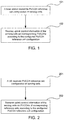
- FIG. 1 is a flowchart of a method executed by a base station according to one embodiment of the present invention.
- Step 101 The base station transmits a configuration message, where PUCCH reference cell configuration information of serving cells is included.
- the base station can transmit the PUCCH reference cell configuration information of a serving cell when the serving cell is added or the serving cell is modified.
- the PUCCH reference cell configuration information can indicate which PUCCH cell that is used by a serving cell to transmit UCI.
- the implementation method of PUCCH reference cells in the 3GPP standard protocol can be seen in examples given by Embodiments 4 to 7 below, but is not limited to these embodiments.
- Step 102 The base station receives uplink control information (UCI) of the serving cell on the corresponding PUCCH according to the configured PUCCH reference cell configuration information of the serving cell.
- UCI uplink control information
- an eNB configures nine serving cells for a UE, which include a PCell and eight SCells (SCells 1 to 8), where the PCell, the SCell 3 and the SCell 6 are configured with PUCCHs.
- the eNB can configure PUCCH reference cells of the SCell 1 and the SCell 2 as the PCell, reference cells of the SCell 4 and the SCell 5 (and the SCell 3) as the SCell 3, and reference cells of the SCell 7 and the SCell 8 (and the SCell 6) as the SCell 6.
- Cell grouping is performed by this configuration method, that is, the PCell and the SCells 1/2 serve as a cell group, the SCells 3/4/5 serve as a cell group, and the SCells 6/7/8 serve as a cell group.
- the UCI of each serving cell is transmitted on the PUCCH of the PUCCH reference cell.
- the method may further include: the base station receives and acquires capability information about whether the UE supports the PUCCH on SCell, the information can be transmitted via an RRC (Radio Resource Control) message, for example, the information can be located in a UE-EUTRA-Capability information element in UECapabilitylnformation.
- the SCells do not include a PSCell in DC.
- An exemplary implementation method for UE capability information in the 3GPP standard protocol is given below:
- FIG. 2 is a flowchartof a method executed by a UE according to one embodiment of the present invention.
- Step 201 The UE receives a configuration message, where PUCCH reference cell configuration information of serving cells is included.
- the UE can receive the PUCCH reference cell configuration information of a serving cell when the serving cell is added or the serving cell is modified.
- the PUCCH reference cell configuration information can indicate which PUCCH cell that is used by the serving cell to transmit UCI.
- the implementation method of PUCCH reference cells in the 3GPP standard protocol can be seen in the examples given by Embodiments 4 to 7 below, but is not limited to these embodiments.
- Step 202 The UE transmits uplink control information (UCI) of the serving cell on the corresponding PUCCH according to the configured PUCCH reference cell configuration information of the serving cell.
- UCI uplink control information
- the method may further include: the UE transmits capability information about whether it supports the PUCCH on SCell to an eNB, as mentioned above.
- FIG. 3 is a flowchart of an information interaction between a base station and a UE according to one embodiment of the present invention.
- Step 301 The eNB transmits a configuration message to the UE, where PUCCH reference cell configuration information of serving cells is included.
- the PUCCH reference cell configuration information can indicate which PUCCH cell s that is used by a serving cell to transmit UCI.
- the information can be transmitted via an RRC message (such as an RRC connection reconfiguration message).
- the PUCCH reference cell configuration information of a serving cell can be transmitted when secondary cell is added or the secondary cell is modified.
- Step 302 The UE receives the PUCCH reference cell configuration information of the serving cells transmitted by the eNB, and returning a response message to the eNB.
- the response message can be an RRC connection reconfiguration completion message.
- the method may further include: the UE and the eNB interact with each other for capability information about whether the UE supports the PUCCH on SCell.
- FIG. 4 is a flowchart of a method executed by a UE according to one embodiment of the present invention.
- the present embodiment provides a method for a UE to transmit UCI of a serving cell on PUCCH channel of corresponding reference cell according to PUCCH reference cell configuration information of the serving cell configured by an eNB.
- the serving cells mean SCells.
- Step 401 The UE receives PUCCH configuration information and/or PUCCH reference cell configuration information of the SCells.
- the PUCCH configuration information of a SCell indicates that the SCell is configured with PUCCH; and the PUCCH reference cell configuration information of a SCell is described as above.
- Step 402 The UE triggers the reporting of UCI of one or more SCells.
- Step 403 The UE determmines whether the SCell is a reference cell. If so, then execute Step 405c, or else execute Step 404. Specifically, in this step, the UE can determine whether the SCell is a reference cell by the following method: if the SCell is configured with PUCCH and/or the PUCCH reference cell of the SCell is configured as own, then the SCell is regarded as a PUCCH reference cell.
- Step 404 The UE determines whether the SCell is configured with a reference cell. If so, then execute Step 405a, or else execute Step 405b.
- Step 405a The UE transmits the UCI of the SCell on the PUCCH of the configured reference cell.
- Step 405b The UE transmits the UCI of the SCell on the PUCCH of a PCell.
- Step 405c The UE transmits the UCI of the SCell on the PUCCH of the SCell.
- Step 404 when the reference cell content of the SCell can be configured as a PCell or an SCell, Step 404 can be omitted. That is, if the result of executing Step 403 is No, then jump to Step 405a. Naturally, Step 405b can also be omitted, because Step 405a and Step 405b can represent the same content at this point.
- FIG. 5 is a flowchart of a method executed by a UE according to one embodiment of the present invention.
- the present embodiment provides a method for a UE to transmit UCI of a serving cell on PUCCHof the corresponding reference cell according to PUCCH reference cell configuration information of the serving cell configured by an eNB.
- a serving cell can be a PCell or an SCell, that is, compisd with Embodiment 2, the present embodiment adds a step for determining whether a serving cell is a PCell.
- Step 501 The UE receives PUCCH configuration information and/or PUCCH reference cell configuration information of a serving cell.
- the PUCCH configuration information of the serving cell indicates that the serving cell is configured with PUCCH; and the PUCCH reference cell configuration information of a serving cell is described as above.
- Step 502 The UE triggers the reporting of UCI of one or more serving cells.
- Step 503 The UE determines whether the serving cell is a PCell, if so, then execute Step 506c, or else execute Step 504.
- Step 504 The UE determines whether the SCell is a reference cell. If so, then execute Step 506c, or else execute Step 505. In this step, the UE can determine whether the SCell is a reference cell by the following method: if the SCell is configured with PUCCH and/or the PUCCH reference cell of the SCell is configured as own, then the SCell is regarded as a PUCCH reference cell.
- Step 505 The UE determines whether the SCell is configured with a reference cell. If so, then execute Step 506a, or else execute Step 506b.
- Step 506a The UE transmits the UCI of the SCell on the PUCCH of the configured reference cell.
- Step 506b The UE transmits the UCI of the SCell on the PUCCH of a PCell.
- Step 506c The UE transmits the UCI of the serving cell on the PUCCH of this serving cell.
- Step 505 when the reference cell content of the SCell can be configured as the PCell or the SCell, Step 505 can be omitted. That is, if the result of executing Step 504 is No, then jump to Step 506a. Naturally, Step 506b can also be omitted, because Step 506a and Step 506b can represent the same content at this point.
- Embodiments 4 to 7 describe the general methods given in Embodiments 2 and 3 in more detail.
- a method for configuring PUCCH reference cell configuration information of a serving cell is as follows:
- PUCCHs of serving cells or SCells can be configured through PUCCH-ConfigCommon information elements, and PUCCH reference cell configuration information of the serving cells or SCells can be configured through PUCCHreference-config information elements.
- SerCellIndex-13 can be used to mark a secondary cell, but it can be replaced by other forms of cell identities for representing a secondary cell.
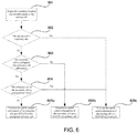
- FIG. 6 is a flowchart of a method executed by a UE according to one embodiment of the present invention.
- Step 601 The UE triggers the reporting of UCI of one or more serving cells.
- Step 602 The UE determines whether the serving cell is a PCell. If so, then execute Step 605c, or else execute Step 603.
- Step 603 The UE determines whether the SCell is configured with reference cell information. If so, then execute Step 604, or else execute Step 605b.
- Step 604 The UE determines whether the reference cell configuration of the SCell is "own". If so, then the cell is a PUCCH reference cell and execute Step 605c, or else execute Step 605a.
- Step 605c The UE transmits the UCI of the serving cell on the PUCCH of this serving cell.
- Step 602 is optional. That is, the UE can transmit UCI of the PCell on the PUCCH of the PCell by default without carrying out determination, and after the UE triggers the reporting of the UCI of the SCell in Step 601, Step 603 is executed directly.
- Step 603 when the content of refrenceCellId-r13 can be set as a PCell or an SCell, Step 603 can be omitted.
- Step 605b can also be omitted, because Step 605b and Step 605a can represent the same content at this point.
- refrenceCellId-r13 can be set as a PCell or an SCell includes the following two types: (1) refrenceCellId-rl3 can be used to mark a serving cell (not only a PCell but also an SCell can be marked), for example, a PCell is marked when SerCellIndex is 0, and an SCell is marked when SerCellIndex is 1 to m (m is a natural number); (2) in the information element of the present embodiment, referenceCellId-r13 can also be the following form:
- SCellIndex is used to mark a secondary cell, and it can be replaced by other forms of cell identities for representing a secondary cell.
- the present embodiment provides a method for a UE to transmit UCI of a serving cell on PUCCH of the corresponding reference cell according to PUCCH reference cell configuration information of the serving cell configured by an eNB.
- a method for configuring PUCCH reference cell configuration information of a serving cell is as follows:
- PUCCHs of serving cells or SCells can be configured through PUCCH-ConfigCommon information elements
- PUCCH reference cell configuration information of the serving cells or SCells can be configured through MSCellToAddMod information elements, and here, MSCell is used to represent a reference cell.
- MSCellIdex is used to mark a secondary cell, and of course, it can be replaced by other cell identities for representing the secondary cell.
- Step 701 The UE triggers the reporting of UCI of one or more serving cells.
- Step 702 The UE determines whether the serving cell is a PCell. If so, then execute Step 705c, or else execute Step 703.
- Step 703 The UE determines whether the SCell is configured as an MSCell. If so, then execute Step 705c, or else execute Step 704.
- Step 704 The UE determines whether the SCell is configured in a scellToAddModMScellList in MSCell configuration information. If so, then execute Step 705a, or else execute Step 705b.
- Step 705a The UE transmits the UCI of the SCell on the PUCCH of the configured reference cell.
- Step 705b The UE transmits the UCI of the SCell on the PUCCH of a PCell.
- Step 705c The UE transmits the UCI of the serving cell the PUCCH of this servingcell.
- Step 702 is optional. That is, the UE can transmit UCI of the PCell on the PUCCH of the PCell by default without carrying out determination. After the UE triggers the reporting of the UCI of the SCell in Step 701, Step 703 is executed directly.
- the present embodiment provides a method for a UE to transmit UCI of a serving cell on PUCCH of the corresponding reference cell according to PUCCH reference cell configuration information of the serving cell configured by an eNB.
- a method for configuring PUCCH reference cell configuration information of a serving cell is as follows:
- PUCCHs of serving cells or SCells can be configured through PUCCH-ConfigCommon information elements, and PUCCH reference cell configuration information of the serving cells or SCells can be configured through PUCCHassociation information elements.
- SerCellIndex can be used to mark a secondary cell, and it can be replaced by other forms of cell identities for representing a secondary cell.
- Step 801 The UE triggers the reporting of UCI of one or more serving cells.
- Step 804 The UE determines whether the SCell is configured with PUCCH association information, i.e. PUCCH reference cell configuration information. If so, then execute Step 805a, or else execute Step 805b.
- PUCCH association information i.e. PUCCH reference cell configuration information.
- Step 805b The UE transmits the UCI of the SCell on a PUCCH of a PCell.
- Step 805c The UE transmits the UCI of the serving cell on a PUCCH of a local cell.
- Step 802 is optional. That is, the UE can transmit UCI of the PCell on the PUCCH of the PCell by default without carrying out determination. After the UE triggers the reporting of the UCI of the SCell in Step 801, Step 803 is executed directly.
- PUCCHCellId-r13 can be set as a PCell or an SCell includes the following two types: (1) SerCellIndex can be used to mark a serving cell (not only a PCell but also an SCell can be marked), for example, a PCell is marked when SerCellIndex is 0, and an SCell is marked when SerCellIndex is 1 to m (m is a natural number); (2) in the information element of the present embodiment, PUCCHCellId-r13 can also be the following form:
- a method for configuring PUCCH reference cell configuration information of serving cells is as follows:
- Step 901 The UE triggers the reporting of UCI of one or more serving cells.
- Step 902 The UE determines whether the serving cell is a PCell. If so, then execute Step 905c, or else execute Step 903.
- Step 903 The UE determines whether the SCell is configured with a PUCCH. If so, then execute Step 905c, or else execute Step 904.
- Step 904 The UE determines whether the SCell is configured in an SCell list in a PUCCH group. If so, then execute Step 905a, or else execute Step 905b.
- Step 905a The UE transmits the UCI of the SCell on a PUCCH of a configured reference cell.
- Step 905b The UE transmits the UCI of the SCell on a PUCCH of a PCell.
- Step 905c The UE transmits the UCI of the serving cell on a PUCCH of a local cell.
- Step 902 is optional. That is, the UE can transmit UCI of the PCell on the PUCCH of the PCell by default without carrying out determination. After the UE triggers the reporting of the UCI of the SCell in Step 901, Step 903 is executed directly.
- Step 904 can be omitted, that is, when the result of executing Step 903 is No, jump to execute Step 905a.
- Step 905b can also be omitted, because Step 905b and Step 905a can represent the same content at this point.
- the case that the content of PUCCHgroupId can be set as a PCell or an SCell includes the following two types: (1) SerCellIndex can be used to mark a serving cell (not only a PCell but also an SCell can be marked), for example, a PCell is marked when SerCellIndex is 0, and an SCell is marked when SerCellIndex is 1 to m (m is a natural number); (2) in the information element of the present embodiment, PUCCHgroupId can also be the following form:
- SCellIndex is used to mark a secondary cell, and it can be replaced by other forms of cell identities for representing a secondary cell.
- the UE 1000 includes: a receiving unit 1001 configured to receive a configuration message from the base station, the configuration message includes PUCCH reference cell configuration information of the serving cells, where reference cells include a primary cell and/or secondary cells configured with PUCCHs, as described above.
- the UE 1000 also includes: a transmission unit 1002 configured to transmit uplink control information of the serving cells on the corresponding PUCCHs according to the PUCCH reference cell configuration information of the serving cells. For example, if a serving cell itselves is a reference cell, the transmission unit 1002 can transmit the uplink control information of the serving cell on the PUCCH of the serving cell. Or, if the serving cell is configured with a reference cell, the transmission unit 1002 can transmit the uplink control information of the serving cell on the PUCCH of the reference cell. In addition, if the serving cell is neither a reference cell nor configured with a reference cell, the transmission unit 1002 can transmit the uplink control information of the serving cell on the PUCCH of the primary cell.
- a transmission unit 1002 configured to transmit uplink control information of the serving cells on the corresponding PUCCHs according to the PUCCH reference cell configuration information of the serving cells. For example, if a serving cell itselves is a reference cell, the transmission unit 1002 can transmit the uplink control information of the
- the uplink control information can include one or more of the following: a channel quality indicator, a precoding matrix index, a rank indicator, a precoding type indicator, and hybrid automatic repeat request feedback.
- the primary cell and the secondary cells can belong to the same base station.
- the secondary cells and the reference cells corresponding thereto can belong to the same base station.
- the PUCCH reference cell configuration information of the serving cells is included in an RRC message.
- FIG. 11 is a block diagram of a base station according to one embodiment of the present invention. As illustrated in FIG. 11 , the base station 1100 includes a transmission unit 1101 and a receiving unit 1102.
- the receiving unit 1102 is configured to receive uplink control information of the serving cells on the corresponding PUCCHs according to the PUCCH reference cell configuration information of the serving cells. For example, if a serving cell itself is a reference cell, the receiving unit 1102 can receive the uplink control information of the serving cell on the PUCCH of the serving cell. Or, if a serving cell is configured with a reference cell, the receiving unit 1102 can receive the uplink control information of the serving cell on the PUCCH of the reference cells. In addition, if a serving cell is neither a reference cell nor configured with a reference cell, the receiving unit 1102 can receive the uplink control information of serthe serving cell on the PUCCH of the primary cell.
- the uplink control information can include one or more of the following: a channel quality indicator, a precoding matrix index, a rank indicator, a precoding type indicator, and hybrid automatic repeat request feedback.
- the primary cell and the secondary cells can belong to the same base station.
- the secondary cells and the reference cells corresponding thereto can belong to the same base station.
- the PUCCH reference cell configuration information of the serving cells is included in an RRC message.
- the PCell in each above-mentioned embodiment of the present invention can also refer to a PSCell.
- the "base station” means a mobile communication data and control switching center with high transmitting power and wide coverage, and includes functions such as resource allocation and scheduling and data receiving and transmission.
- the "user equipment” means a user mobile terminal, such as terminal equipment capable of performing radio communication with base stations or micro base stations, including mobile phones and laptop computers.
- the embodiments of the present invention disclosed herein can be implemented on a computer program product.
- the computer program product is the following product: the product is provided with a computer-readable medium, a computer program logic is coded on the computer-readable medium, and when executed on a computing device, the computer program logic provides related operation to implement the above-mentioned technical solution of the present invention.
- the computer program logic When executed on at least one processor of the computing system, the computer program logic makes the processor execute the operation (method) described by the embodiments of the present invention.
- Such setting of the present invention is typically provided as software, codes and/or other data structures arranged or coded on computer-readable media, such as optical media (for example, CD-ROM), floppy discs or hard discs, or other media for firmware or microcodes on, for example, one or more ROM or RAM or PROM chips or downloadable software images, shared databases and the like in one or more modules.
- the software or the firmware or such configuration can be installed on a computing device, so that one or more processors in the computing device can execute the technical solution described in the embodiments of the present invention.
Landscapes
- Engineering & Computer Science (AREA)
- Signal Processing (AREA)
- Computer Networks & Wireless Communication (AREA)
- Mobile Radio Communication Systems (AREA)
Abstract
Description
- The present invention relates to the technical field of radio communication. More specifically, the present invention relates to a resource configuration method for communication between devices, a base station and a user equipment.
- With the development of mobile communication and the diversification of services, increasingly higher requirements are put forward on the transmission rate of communication systems. Carrier aggregation (CA) technology has been introduced into 3GPP Release 10 and Release 11, and is used to increase the downlink and uplink speeds of a system. That is, a user equipment (UE) can be configured with multiple carriers at the same time, and can simultaneously perform transmission and reception on these multiple carriers, which, compared with prior single-carrier transmission, greatly increases transmission speed and resource utilization rate.
- In 3GPP Release 10 and Release 11, a serving base station (eNB) configures multiple carriers for the user equipment, and these carriers belong to the same base station. A cell which corresponds to the primary component carrier (PCC) of the serving base station is called a primary cell (PCell), and the primary component carrier provides radio resource control connection between the UE and the eNB and a transmission resource. A cell which corresponds to the secondary component carrier (SCC) of the serving base station is called a secondary cell (SCell), and the secondary cell is mainly used to provide a transmission resource. A PCell and one or more SCells are included in serving cells corresponding to the multiple carriers configured for the UE. In the R10/11 version of protocol, the UE can, at most, support eight serving cells at the same time.
- In the R10/11 version of CA, only the configuration of physical uplink control channels (PUCCH) on the PCells is supported. That is, for a UE, configured SCells thereof do not have PUCCHs. Uplink control information (UCI) which is needed to optimize downlink transmission, such as a channel quality indicator, and hybrid automatic repeat request feedback (HARQ), needs to be transmitted via a PUCCH. In this case, the UCI corresponding to all the SCells needs to be carried by the PUCCH of the PCell.
- The dual connectivity (DC) technology is introduced into 3GPP Release 12 to increase user throughput and improve mobility performance. When DC is configured, the UE can simultaneously communicate with two eNBs, each base station can maintain cell configuration similar to R10/R11 CA, and are divided into a master base station (Master eNB) and a secondary base station (Secondary eNB). In this case, for a UE, the MeNB can include a PCell and one or more SCell; and the SeNB can include a primary secondary cell (PSCell) and one or more SCells. PUCCHs can be configured on the PCell and the PSCell. Just as in CA, UCI of the PCell and SCells included in all the serving cells belonging to the MeNB is carried on the PUCCH of the PCell, and UCI of the PSCell and SCells included in all the serving cells belonging to the SeNB is carried on the PUCCH of the PSCell.
- In ongoing Release 13, the enhanced CA technology (eCA) is being discussed. In eCA, PUCCHs on SCells are introduced, and moreover, the number of carriers capable of being simultaneously supported by a UE is increased to 32, so that the system resource utilization rate can be increased. However, adopting the PUCCH of a PCell or an SCell to carry the UCI of an SCell and adopting the PUCCH of which SCell to carry the UCI under SCell PUCCH configuration is an urgent problem that needs to be solved.
- According to a first aspect of the present invention, provided is a method executed by a base station, where the base station communicates with a user equipment, the user equipment is configured with multiple carriers corresponding to multiple serving cells, the multiple serving cells include a primary cell and one or more secondary cells, and the method includes: transmitting a configuration message to the user equipment, where the configuration message includes physical uplink control channel (PUCCH) reference cell configuration information of the serving cells, and reference cells include a primary cell and/or secondary cells configured with PUCCHs; and receiving uplink control information of the serving cells on the corresponding PUCCHs according to the PUCCH reference cell configuration information of the serving cells.
- In one embodiment, if the serving cells themselves are the reference cells, the uplink control information of the serving cells is received on the PUCCHs of the serving cells. Alternatively, if the serving cells are configured with reference cells, the uplink control information of the serving cells is received on the PUCCHs of the reference cells.
- In one embodiment, if the serving cells are neither the reference cells nor configured with the reference cells, the uplink control information of the serving cells is received on the PUCCH of the primary cell.
- In one embodiment, the uplink control information includes one or more of the following: a channel quality indicator, a precoding matrix index, a rank indicator, a precoding type indicator, and hybrid automatic repeat request feedback.
- In one embodiment, the primary cell and the secondary cells belong to the same base station. Alternatively, the secondary cells and the reference cells corresponding thereto belong to the same base station.
- In one embodiment, the PUCCH reference cell configuration information of the serving cells is included in a radio resource control (RRC) message.
- According to a second aspect of the present invention, provided is a method executed by a user equipment, where the user equipment communicates with a base station, the user equipment is configured with multiple carriers corresponding to multiple serving cells, the multiple serving cells include a primary cell and one or more secondary cells, and the method includes: receiving a configuration message from the base station, where the configuration message includes physical uplink control channel (PUCCH) reference cell configuration information of the serving cells, and reference cells include a primary cell and/or secondary cells configured with PUCCHs; and transmitting uplink control information of the serving cells on the corresponding PUCCHs according to the PUCCH reference cell configuration information of the serving cells.
- In one embodiment, if the serving cells themselves are the reference cells, the uplink control information of the serving cells is transmitted on the PUCCHs of the serving cells. Alternatively, if the serving cells are configured with reference cells, the uplink control information of the serving cells is transmitted on the PUCCHs of the reference cells.
- In one embodiment, if the serving cells are neither the reference cells nor configured with the reference cells, the uplink control information of the serving cells is transmitted on the PUCCH of the primary cell.
- In one embodiment, the uplink control information includes one or more of the following: a channel quality indicator, a precoding matrix index, a rank indicator, a precoding type indicator, and hybrid automatic repeat request feedback.
- In one embodiment, the primary cell and the secondary cells belong to the same base station. Alternatively, the secondary cells and the reference cells corresponding thereto belong to the same base station.
- In one embodiment, the PUCCH reference cell configuration information of the serving cells is included in a radio resource control (RRC) message.
- According to a third aspect of the present invention, provided is a base station, where the base station communicates with a user equipment, the user equipment is configured with multiple carriers corresponding to multiple serving cells, the multiple serving cells include a primary cell and one or more secondary cells, and the base station includes: a transmission unit configured to transmit a configuration message to the user equipment, where the configuration message includes physical uplink control channel (PUCCH) reference cell configuration information of the serving cells, and reference cells include a primary cell and/or secondary cells configured with PUCCHs; and a receiving unit configured to receive uplink control information of the serving cells on the corresponding PUCCHs according to the PUCCH reference cell configuration information of the serving cells.
- In one embodiment, if the serving cells themselves are the reference cells, the receiving unit receives the uplink control information of the serving cells on the PUCCHs of the serving cells. Alternatively, if the serving cells are configured with reference cells, the receiving unit receives the uplink control information of the serving cells on the PUCCHs of the reference cells.
- In one embodiment, if the serving cells are neither the reference cells nor configured with the reference cells, the receiving unit receives the uplink control information of the serving cells on the PUCCH of the primary cell.
- In one embodiment, the uplink control information includes one or more of the following: a channel quality indicator, a precoding matrix index, a rank indicator, a precoding type indicator, and hybrid automatic repeat request feedback.
- In one embodiment, the primary cell and the secondary cells belong to the same base station. Alternatively, the secondary cells and the reference cells corresponding thereto belong to the same base station.
- In one embodiment, the PUCCH reference cell configuration information of the serving cells is included in a radio resource control (RRC) message.
- According to a fourth aspect of the present invention, provided is a user equipment, where the user equipment communicates with a base station, the user equipment is configured with multiple carriers corresponding to multiple serving cells, the multiple serving cells include a primary cell and one or more secondary cells, and the user equipment includes: a receiving unit configured to receive a configuration message from the base station, where the configuration message includes physical uplink control channel (PUCCH) reference cell configuration information of the serving cells, and reference cells include a primary cell and/or secondary cells configured with PUCCHs; and a transmission unit configured to transmit uplink control information of the serving cells on the corresponding PUCCHs according to the PUCCH reference cell configuration information of the serving cells.
- In one embodiment, if the serving cells themselves are the reference cells, the transmission unit transmits the uplink control information of the serving cells on the PUCCHs of the serving cells. Alternatively, if the serving cells are configured with reference cells, the transmission unit transmits the uplink control information of the serving cells on the PUCCHs of the reference cells.
- In one embodiment, if the serving cells are neither the reference cells nor configured with the reference cells, the transmission unit transmits the uplink control information of the serving cells on the PUCCH of the primary cell.
- In one embodiment, the uplink control information includes one or more of the following: a channel quality indicator, a precoding matrix index, a rank indicator, a precoding type indicator and hybrid automatic repeat request feedback.
- In one embodiment, the primary cell and the secondary cells belong to the same base station. Alternatively, the secondary cells and the reference cells corresponding thereto belong to the same base station.
- In one embodiment, the PUCCH reference cell configuration information of the serving cells is included in a radio resource control (RRC) message.
- The present invention allows the base station to flexibly configure multiple PUCCH reference cells, configure different PUCCH reference cells according to different cell loads, and choose suitable PUCCH reference cells for serving cells to perform corresponding UCI transmission. By means of the present invention, the user equipment can carry out UCI transmission on corresponding PUCCHs according to the configuration of the base station, so that load balance between the multiple PUCCHs is realized in UCI transmission.
- The multiple aspects of the present invention can be better understood in reference to the following drawings. Parts in the drawings are not drawn proportionally, but are only intended to show the principle of the present invention. In order to conveniently show and describe some parts of the present invention, corresponding portions in the drawings may be magnified or minimized.
- Elements and features described in one drawing or embodiment of the present invention can be combined with elements and features shown in one or more other drawings or embodiments. In addition, in the drawings, similar callouts represent the corresponding parts in the multiple drawings, and can be used to indicate the corresponding parts used in more than one embodiment.
-
FIG. 1 is a flowchart of a method executed by a base station according to one embodiment of the present invention. -
FIG. 2 is a flowchart of a method executed by a UE according to one embodiment of the present invention. -
FIG. 3 is a flowchart of an information interaction between a base station and a UE according to one embodiment of the present invention. -
FIG. 4 is a flowchart of a method executed by a UE according to one embodiment of the present invention. -
FIG. 5 is a flowchart of a method executed by a UE according to one embodiment of the present invention. -
FIG. 6 is a flowchart of a method executed by a UE according to one embodiment of the present invention. -
FIG. 7 is a flowchart of a method executed by a UE according to one embodiment of the present invention. -
FIG. 8 is a flowchart of a method executed by a UE according to one embodiment of the present invention. -
FIG. 9 is a flowchart of a method executed by a UE according to one embodiment of the present invention. -
FIG. 10 is a block diagram of a UE according to one embodiment of the present invention. -
FIG. 11 is a block diagram of a base station according to one embodiment of the present invention. - By referring to the drawings, by means of the specification below, the foregoing and other features of the present invention will become clear. In the specification and the drawings, specific embodiments of the present invention are disclosed particularly, and indicates parts of the embodiments of the principle of the present invention that can be adopted. It should be known that the present invention is not limited to the described embodiments, and on the contrary, the present invention includes all modifications, variations and equivalents which fall within the coverage of the attached claims. In addition, for the sake of simplicity and convenience, the detailed description of the conventional technology without direct association with the present invention is omitted in order to prevent the understanding of the present invention from being confused.
- The present invention is not limited to eCA systems of R13, and is also applicable to other devices and systems adopting the multi-carrier technology, such as a DC+eCA system.
- In reference to the drawings and the specific embodiments, the following describes cell grouping in an enhanced CA scenario which is put forward by the present invention. Specifically, with an LTE mobile communication system and subsequent evolved version thereof as an exemplary application environment and R13 eCA as an implementing technology scenario (that is, a UE which supports CA works under an eNB, PUCCHs of SCells can be configured, and optionally, 32 carriers can be supported as well), multiple embodiments based on the present invention are described hereinafter. However, it needs to be indicated that the present invention is not limited to the following embodiments, but is applicable to other radio communication systems, such as the future 5G cellular communication system.
- In the present invention, UCI can include one or more or any combination of a channel quality indicator (CQI), a precoding matrix index (PMI), a rank indicator (RI), a precoding type indicator (PTI), and an HARQ feedback indicator.
-
FIG. 1 is a flowchart of a method executed by a base station according to one embodiment of the present invention. - Step 101: The base station transmits a configuration message, where PUCCH reference cell configuration information of serving cells is included. For example, the base station can transmit the PUCCH reference cell configuration information of a serving cell when the serving cell is added or the serving cell is modified. The PUCCH reference cell configuration information can indicate which PUCCH cell that is used by a serving cell to transmit UCI. The implementation method of PUCCH reference cells in the 3GPP standard protocol can be seen in examples given by Embodiments 4 to 7 below, but is not limited to these embodiments.
- Step 102: The base station receives uplink control information (UCI) of the serving cell on the corresponding PUCCH according to the configured PUCCH reference cell configuration information of the serving cell.
- An example of a cell grouping method based on PUCCH reference cells is illustrated below. It is assumed that an eNB configures nine serving cells for a UE, which include a PCell and eight SCells (SCells 1 to 8), where the PCell, the SCell 3 and the SCell 6 are configured with PUCCHs. In this case, the eNB can configure PUCCH reference cells of the SCell 1 and the SCell 2 as the PCell, reference cells of the SCell 4 and the SCell 5 (and the SCell 3) as the SCell 3, and reference cells of the SCell 7 and the SCell 8 (and the SCell 6) as the SCell 6. Cell grouping is performed by this configuration method, that is, the PCell and the SCells 1/2 serve as a cell group, the SCells 3/4/5 serve as a cell group, and the SCells 6/7/8 serve as a cell group. In a cell group, the UCI of each serving cell is transmitted on the PUCCH of the PUCCH reference cell.
- Alternatively, before
Step 101, the method may further include: the base station receives and acquires capability information about whether the UE supports the PUCCH on SCell, the information can be transmitted via an RRC (Radio Resource Control) message, for example, the information can be located in a UE-EUTRA-Capability information element in UECapabilitylnformation. Here, the SCells do not include a PSCell in DC. An exemplary implementation method for UE capability information in the 3GPP standard protocol is given below:
-
FIG. 2 is a flowchartof a method executed by a UE according to one embodiment of the present invention. - Step 201: The UE receives a configuration message, where PUCCH reference cell configuration information of serving cells is included. In the present embodiment, the UE can receive the PUCCH reference cell configuration information of a serving cell when the serving cell is added or the serving cell is modified. The PUCCH reference cell configuration information can indicate which PUCCH cell that is used by the serving cell to transmit UCI. The implementation method of PUCCH reference cells in the 3GPP standard protocol can be seen in the examples given by Embodiments 4 to 7 below, but is not limited to these embodiments.
- Step 202: The UE transmits uplink control information (UCI) of the serving cell on the corresponding PUCCH according to the configured PUCCH reference cell configuration information of the serving cell. The specific process will be introduced in detail in Embodiments 4 to 7, but is not limited to these embodiments. Preferably, before
Step 201, the method may further include: the UE transmits capability information about whether it supports the PUCCH on SCell to an eNB, as mentioned above. -
FIG. 3 is a flowchart of an information interaction between a base station and a UE according to one embodiment of the present invention. - Step 301: The eNB transmits a configuration message to the UE, where PUCCH reference cell configuration information of serving cells is included. The PUCCH reference cell configuration information can indicate which PUCCH cell s that is used by a serving cell to transmit UCI.
- For example, the information can be transmitted via an RRC message (such as an RRC connection reconfiguration message). Specifically, the PUCCH reference cell configuration information of a serving cell can be transmitted when secondary cell is added or the secondary cell is modified.
- Step 302: The UE receives the PUCCH reference cell configuration information of the serving cells transmitted by the eNB, and returning a response message to the eNB. For example, the response message can be an RRC connection reconfiguration completion message.
- Preferably, before Step 301, the method may further include: the UE and the eNB interact with each other for capability information about whether the UE supports the PUCCH on SCell.
-
FIG. 4 is a flowchart of a method executed by a UE according to one embodiment of the present invention. The present embodiment provides a method for a UE to transmit UCI of a serving cell on PUCCH channel of corresponding reference cell according to PUCCH reference cell configuration information of the serving cell configured by an eNB. In the present embodiment, the serving cells mean SCells. - Step 401: The UE receives PUCCH configuration information and/or PUCCH reference cell configuration information of the SCells. The PUCCH configuration information of a SCell indicates that the SCell is configured with PUCCH; and the PUCCH reference cell configuration information of a SCell is described as above.
- Step 402: The UE triggers the reporting of UCI of one or more SCells.
- Step 403: The UE determmines whether the SCell is a reference cell. If so, then execute
Step 405c, or else executeStep 404. Specifically, in this step, the UE can determine whether the SCell is a reference cell by the following method: if the SCell is configured with PUCCH and/or the PUCCH reference cell of the SCell is configured as own, then the SCell is regarded as a PUCCH reference cell. - Step 404: The UE determines whether the SCell is configured with a reference cell. If so, then execute
Step 405a, or else executeStep 405b. -
Step 405a: The UE transmits the UCI of the SCell on the PUCCH of the configured reference cell. -
Step 405b: The UE transmits the UCI of the SCell on the PUCCH of a PCell. -
Step 405c: The UE transmits the UCI of the SCell on the PUCCH of the SCell. - Among the above-mentioned steps, when the reference cell content of the SCell can be configured as a PCell or an SCell,
Step 404 can be omitted. That is, if the result of executingStep 403 is No, then jump to Step 405a. Naturally, Step 405b can also be omitted, becauseStep 405a andStep 405b can represent the same content at this point. -
FIG. 5 is a flowchart of a method executed by a UE according to one embodiment of the present invention. The present embodiment provides a method for a UE to transmit UCI of a serving cell on PUCCHof the corresponding reference cell according to PUCCH reference cell configuration information of the serving cell configured by an eNB. In the present embodiment, a serving cell can be a PCell or an SCell, that is, compisd with Embodiment 2, the present embodiment adds a step for determining whether a serving cell is a PCell. - Step 501: The UE receives PUCCH configuration information and/or PUCCH reference cell configuration information of a serving cell. The PUCCH configuration information of the serving cell indicates that the serving cell is configured with PUCCH; and the PUCCH reference cell configuration information of a serving cell is described as above.
- Step 502: The UE triggers the reporting of UCI of one or more serving cells.
- Step 503: The UE determines whether the serving cell is a PCell, if so, then execute
Step 506c, or else executeStep 504. - Step 504: The UE determines whether the SCell is a reference cell. If so, then execute
Step 506c, or else executeStep 505. In this step, the UE can determine whether the SCell is a reference cell by the following method: if the SCell is configured with PUCCH and/or the PUCCH reference cell of the SCell is configured as own, then the SCell is regarded as a PUCCH reference cell. - Step 505: The UE determines whether the SCell is configured with a reference cell. If so, then execute
Step 506a, or else executeStep 506b. -
Step 506a: The UE transmits the UCI of the SCell on the PUCCH of the configured reference cell. -
Step 506b: The UE transmits the UCI of the SCell on the PUCCH of a PCell. -
Step 506c: The UE transmits the UCI of the serving cell on the PUCCH of this serving cell. - Among the above-mentioned steps, when the reference cell content of the SCell can be configured as the PCell or the SCell,
Step 505 can be omitted. That is, if the result of executingStep 504 is No, then jump to Step 506a. Naturally, Step 506b can also be omitted, becauseStep 506a andStep 506b can represent the same content at this point. - General processing flows of the UE performing UCI transmission according to the PUCCH reference cell in the present invention are given in above-mentioned Embodiments 2 and 3. Several types of specific information element implementation methods for PUCCH reference cell configuration information in the 3GPP standard protocol are given in Embodiments 4 to 7 below. In combination with these several types of information element representation methods, Embodiments 4 to 7 describe the general methods given in Embodiments 2 and 3 in more detail.
- The present embodiment provides a method for a UE to transmit UCI of a serving cell on PUCCH of the corresponding reference cell according to PUCCH reference cell configuration information of the serving cell configured by an eNB.
- In the present embodiment, a method for configuring PUCCH reference cell configuration information of a serving cell is as follows:


- PUCCHs of serving cells or SCells can be configured through PUCCH-ConfigCommon information elements, and PUCCH reference cell configuration information of the serving cells or SCells can be configured through PUCCHreference-config information elements. SerCellIndex-13 can be used to mark a secondary cell, but it can be replaced by other forms of cell identities for representing a secondary cell.
-
FIG. 6 is a flowchart of a method executed by a UE according to one embodiment of the present invention. - Step 601: The UE triggers the reporting of UCI of one or more serving cells.
- Step 602: The UE determines whether the serving cell is a PCell. If so, then execute
Step 605c, or else executeStep 603. - Step 603: The UE determines whether the SCell is configured with reference cell information. If so, then execute
Step 604, or else executeStep 605b. - Step 604: The UE determines whether the reference cell configuration of the SCell is "own". If so, then the cell is a PUCCH reference cell and execute
Step 605c, or else executeStep 605a. -
Step 605a: The UE transmits the UCI of the SCell on the PUCCH of a configured reference cell. -
Step 605b: The UE transmits the UCI of the SCell on the PUCCH of a PCell. -
Step 605c: The UE transmits the UCI of the serving cell on the PUCCH of this serving cell. - Among the above-mentioned steps,
Step 602 is optional. That is, the UE can transmit UCI of the PCell on the PUCCH of the PCell by default without carrying out determination, and after the UE triggers the reporting of the UCI of the SCell inStep 601,Step 603 is executed directly. - In addition, when the content of refrenceCellId-r13 can be set as a PCell or an SCell,
Step 603 can be omitted. Naturally, Step 605b can also be omitted, becauseStep 605b andStep 605a can represent the same content at this point. - In addition, the case that the content of refrenceCellId-r13 can be set as a PCell or an SCell includes the following two types: (1) refrenceCellId-rl3 can be used to mark a serving cell (not only a PCell but also an SCell can be marked), for example, a PCell is marked when SerCellIndex is 0, and an SCell is marked when SerCellIndex is 1 to m (m is a natural number); (2) in the information element of the present embodiment, referenceCellId-r13 can also be the following form:

- SCellIndex is used to mark a secondary cell, and it can be replaced by other forms of cell identities for representing a secondary cell.
- The present embodiment provides a method for a UE to transmit UCI of a serving cell on PUCCH of the corresponding reference cell according to PUCCH reference cell configuration information of the serving cell configured by an eNB.
- In the present embodiment, a method for configuring PUCCH reference cell configuration information of a serving cell is as follows:


- PUCCHs of serving cells or SCells can be configured through PUCCH-ConfigCommon information elements, PUCCH reference cell configuration information of the serving cells or SCells can be configured through MSCellToAddMod information elements, and here, MSCell is used to represent a reference cell. In addition, SCellIdex is used to mark a secondary cell, and of course, it can be replaced by other cell identities for representing the secondary cell.
-
FIG. 7 is a flowchart of a method executed by a UE according to one embodiment of the present invention. - Step 701: The UE triggers the reporting of UCI of one or more serving cells.
- Step 702: The UE determines whether the serving cell is a PCell. If so, then execute
Step 705c, or else executeStep 703. - Step 703: The UE determines whether the SCell is configured as an MSCell. If so, then execute
Step 705c, or else executeStep 704. - Step 704: The UE determines whether the SCell is configured in a scellToAddModMScellList in MSCell configuration information. If so, then execute
Step 705a, or else executeStep 705b. -
Step 705a: The UE transmits the UCI of the SCell on the PUCCH of the configured reference cell. -
Step 705b: The UE transmits the UCI of the SCell on the PUCCH of a PCell. -
Step 705c: The UE transmits the UCI of the serving cell the PUCCH of this servingcell. - Among the above-mentioned steps,
Step 702 is optional. That is, the UE can transmit UCI of the PCell on the PUCCH of the PCell by default without carrying out determination. After the UE triggers the reporting of the UCI of the SCell inStep 701,Step 703 is executed directly. - The present embodiment provides a method for a UE to transmit UCI of a serving cell on PUCCH of the corresponding reference cell according to PUCCH reference cell configuration information of the serving cell configured by an eNB.
- In the present embodiment, a method for configuring PUCCH reference cell configuration information of a serving cell is as follows:


- PUCCHs of serving cells or SCells can be configured through PUCCH-ConfigCommon information elements, and PUCCH reference cell configuration information of the serving cells or SCells can be configured through PUCCHassociation information elements. In addition, SerCellIndex can be used to mark a secondary cell, and it can be replaced by other forms of cell identities for representing a secondary cell.
-
FIG. 8 is a flowchart of a method executed by a UE according to one embodiment of the present invention. - Step 801: The UE triggers the reporting of UCI of one or more serving cells.
- Step 802: The UE determines whether the serving cell is a PCell. If so, then execute
Step 805c, or else executeStep 803. - Step 803: The UE determines whether the SCell is configured with a PUCCH. If so, then execute
Step 805c, or else executeStep 804. - Step 804: The UE determines whether the SCell is configured with PUCCH association information, i.e. PUCCH reference cell configuration information. If so, then execute
Step 805a, or else executeStep 805b. -
Step 805a: The UE transmits the UCI of the SCell on a PUCCH of a configured reference cell. -
Step 805b: The UE transmits the UCI of the SCell on a PUCCH of a PCell. -
Step 805c: The UE transmits the UCI of the serving cell on a PUCCH of a local cell. - Among the above-mentioned steps,
Step 802 is optional. That is, the UE can transmit UCI of the PCell on the PUCCH of the PCell by default without carrying out determination. After the UE triggers the reporting of the UCI of the SCell inStep 801,Step 803 is executed directly. - In addition, when the content of PUCCHCellId-r13 can be set as a PCell or an SCell,
Step 804 can be omitted. That is, when the result of executingStep 803 is No, jump to executeStep 805a. Naturally, Step 805b can also be omitted, becauseStep 805b andStep 805a can represent the same content at this point. - In addition, the case that the content of PUCCHCellId-r13 can be set as a PCell or an SCell includes the following two types: (1) SerCellIndex can be used to mark a serving cell (not only a PCell but also an SCell can be marked), for example, a PCell is marked when SerCellIndex is 0, and an SCell is marked when SerCellIndex is 1 to m (m is a natural number); (2) in the information element of the present embodiment, PUCCHCellId-r13 can also be the following form:

- SCellIndex is used to mark a secondary cell, and it can be replaced by other forms of cell identities for representing a secondary cell.
- The present embodiment provides a method for a UE to transmit UCI of a serving cell on PUCCH of the corresponding reference cell according to PUCCH reference cell configuration information of the serving cell configured by an eNB.
- In the present embodiment, a method for configuring PUCCH reference cell configuration information of serving cells is as follows:
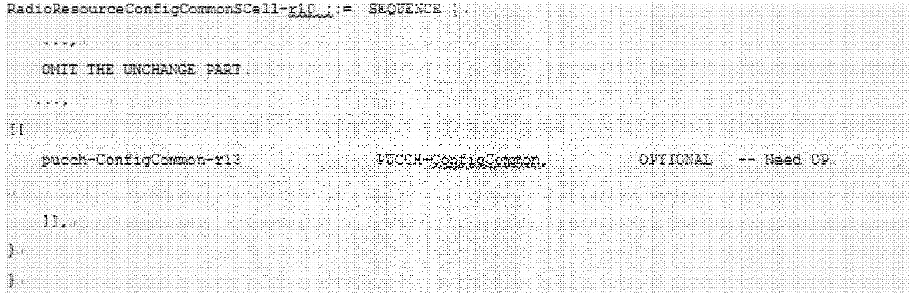

- PUCCHs of serving cells or SCells can be configured through PUCCH-ConfigCommon information elements, and PUCCH reference cell configuration information of the serving cells or SCells can be configured through PUCCHgroup association information elements. In addition, SerCellIndex and SCellIdex are used to mark a secondary cell, and they can be replaced by other forms of cell identities for representing a secondary cell.
-
FIG. 9 is a flowchart of a method executed by a UE according to one embodiment of the present invention. - Step 901: The UE triggers the reporting of UCI of one or more serving cells.
- Step 902: The UE determines whether the serving cell is a PCell. If so, then execute Step 905c, or else execute
Step 903. - Step 903: The UE determines whether the SCell is configured with a PUCCH. If so, then execute Step 905c, or else execute
Step 904. - Step 904: The UE determines whether the SCell is configured in an SCell list in a PUCCH group. If so, then execute
Step 905a, or else executeStep 905b. -
Step 905a: The UE transmits the UCI of the SCell on a PUCCH of a configured reference cell. -
Step 905b: The UE transmits the UCI of the SCell on a PUCCH of a PCell. - Step 905c: The UE transmits the UCI of the serving cell on a PUCCH of a local cell.
- Among the above-mentioned steps,
Step 902 is optional. That is, the UE can transmit UCI of the PCell on the PUCCH of the PCell by default without carrying out determination. After the UE triggers the reporting of the UCI of the SCell inStep 901,Step 903 is executed directly. - In addition, when the content of PUCCHgroupId can be set as a PCell or an SCell,
Step 904 can be omitted, that is, when the result of executingStep 903 is No, jump to executeStep 905a. Naturally, Step 905b can also be omitted, becauseStep 905b andStep 905a can represent the same content at this point. - In addition, the case that the content of PUCCHgroupId can be set as a PCell or an SCell includes the following two types: (1) SerCellIndex can be used to mark a serving cell (not only a PCell but also an SCell can be marked), for example, a PCell is marked when SerCellIndex is 0, and an SCell is marked when SerCellIndex is 1 to m (m is a natural number); (2) in the information element of the present embodiment, PUCCHgroupId can also be the following form:

- SCellIndex is used to mark a secondary cell, and it can be replaced by other forms of cell identities for representing a secondary cell.
-
FIG. 10 is a block diagram of a UE according to one embodiment of the present invention. The present embodiment provides a structural block diagram of a UE device for transmitting UCI of a serving cell on PUCCHof corresponding reference cells according to PUCCH reference cell configuration information of the serving cell configured by an eNB. - As illustrated in
FIG. 10 , theUE 1000 includes: a receivingunit 1001 configured to receive a configuration message from the base station, the configuration message includes PUCCH reference cell configuration information of the serving cells, where reference cells include a primary cell and/or secondary cells configured with PUCCHs, as described above. - As illustrated in
FIG. 10 , theUE 1000 also includes: atransmission unit 1002 configured to transmit uplink control information of the serving cells on the corresponding PUCCHs according to the PUCCH reference cell configuration information of the serving cells. For example, if a serving cell itselves is a reference cell, thetransmission unit 1002 can transmit the uplink control information of the serving cell on the PUCCH of the serving cell. Or, if the serving cell is configured with a reference cell, thetransmission unit 1002 can transmit the uplink control information of the serving cell on the PUCCH of the reference cell. In addition, if the serving cell is neither a reference cell nor configured with a reference cell, thetransmission unit 1002 can transmit the uplink control information of the serving cell on the PUCCH of the primary cell. - In an example, the uplink control information can include one or more of the following: a channel quality indicator, a precoding matrix index, a rank indicator, a precoding type indicator, and hybrid automatic repeat request feedback.
- In an example, the primary cell and the secondary cells can belong to the same base station. Alternatively, the secondary cells and the reference cells corresponding thereto can belong to the same base station.
- In an example, the PUCCH reference cell configuration information of the serving cells is included in an RRC message.
-
FIG. 11 is a block diagram of a base station according to one embodiment of the present invention. As illustrated inFIG. 11 , thebase station 1100 includes atransmission unit 1101 and areceiving unit 1102. - The
transmission unit 1101 is configured to transmit a configuration message to the user equipment, the configuration message includes PUCCH reference cell configuration information of serving cells, where reference cells include a primary cell and/or secondary cells configured with PUCCHs. - The receiving
unit 1102 is configured to receive uplink control information of the serving cells on the corresponding PUCCHs according to the PUCCH reference cell configuration information of the serving cells. For example, if a serving cell itself is a reference cell, the receivingunit 1102 can receive the uplink control information of the serving cell on the PUCCH of the serving cell. Or, if a serving cell is configured with a reference cell, the receivingunit 1102 can receive the uplink control information of the serving cell on the PUCCH of the reference cells. In addition, if a serving cell is neither a reference cell nor configured with a reference cell, the receivingunit 1102 can receive the uplink control information of serthe serving cell on the PUCCH of the primary cell. - In an example, the uplink control information can include one or more of the following: a channel quality indicator, a precoding matrix index, a rank indicator, a precoding type indicator, and hybrid automatic repeat request feedback.
- In an example, the primary cell and the secondary cells can belong to the same base station. Alternatively, the secondary cells and the reference cells corresponding thereto can belong to the same base station.
- In an example, the PUCCH reference cell configuration information of the serving cells is included in an RRC message.
- Note that when the present invention is applied in the DC scenario (that is, the UE is served by two eNBs at the same time), the PCell in each above-mentioned embodiment of the present invention can also refer to a PSCell.
- It should be understood that the above-mentioned embodiments of the present invention can be implemented by software, hardware, or a combination of software and hardware. For example, the various components in the base station and the user equipment in the above-mentioned embodiments can be implemented by a variety of devices, and these devices include, but are not limited to: an analog circuit device, a digital circuit device, a digital signal processing (DSP) circuit, a programmable processor, an application-specific integrated circuit (ASIC), a field programmable gate array (FPGA), a complex programmable logic device (CPLD), and the like.
- In the present application, the "base station" means a mobile communication data and control switching center with high transmitting power and wide coverage, and includes functions such as resource allocation and scheduling and data receiving and transmission. The "user equipment" means a user mobile terminal, such as terminal equipment capable of performing radio communication with base stations or micro base stations, including mobile phones and laptop computers.
- The specific embodiments of the present invention are disclosed in detail above. It should be understood that features described and/or illustrated for one embodiment can be used in one or more other embodiments in the same or similar way to combine with the features in the other embodiments or substitute for the features in other embodiments.
- It should be emphasized that the term "comprise/include" means the existence of the features, the steps or the components when used in this article, but does not exclude the existence or addition of one or more other features, steps or components.
- In addition, the embodiments of the present invention disclosed herein can be implemented on a computer program product. More specifically, the computer program product is the following product: the product is provided with a computer-readable medium, a computer program logic is coded on the computer-readable medium, and when executed on a computing device, the computer program logic provides related operation to implement the above-mentioned technical solution of the present invention. When executed on at least one processor of the computing system, the computer program logic makes the processor execute the operation (method) described by the embodiments of the present invention. Such setting of the present invention is typically provided as software, codes and/or other data structures arranged or coded on computer-readable media, such as optical media (for example, CD-ROM), floppy discs or hard discs, or other media for firmware or microcodes on, for example, one or more ROM or RAM or PROM chips or downloadable software images, shared databases and the like in one or more modules. The software or the firmware or such configuration can be installed on a computing device, so that one or more processors in the computing device can execute the technical solution described in the embodiments of the present invention.
- Although the present invention has been illustrated in reference to the preferred embodiments of the present invention, those skilled in the prior art shall understand that under the condition of not departing from the spirit and scope of the present invention, various modifications, replacements and changes can be made on the present invention. Therefore, the present invention should be limited by the attached claims and equivalents thereof rather than the above-mentioned embodiments.
Claims (24)
- A method executed by a base station, the base station communicating with a user equipment, the user equipment being configured with a plurality of carriers corresponding to a plurality of serving cells, and the plurality of serving cells including a primary cell and one or more secondary cells, the method comprising:transmitting a configuration message to the user equipment, wherein the configuration message includes physical uplink control channel (PUCCH) reference cell configuration information of the serving cells, and reference cells includes a primary cell and/or secondary cells configured with PUCCHs; andreceiving uplink control information of the serving cells on the corresponding PUCCHs according to the PUCCH reference cell configuration information of the serving cells.
- The method according to claim 1, wherein
if the serving cells themselves are the reference cells, the uplink control information of the serving cells is received on the PUCCHs of the serving cells; or
if the serving cells are configured with reference cells, the uplink control information of the serving cells is received on the PUCCHs of the reference cells. - The method according to claim 1, wherein
if the serving cells are neither the reference cells nor configured with the reference cells, the uplink control information of the serving cells is received on the PUCCH of the primary cell. - The method according to claim 1, wherein the uplink control information includes one or more of: a channel quality indicator, a precoding matrix index, a rank indicator, a precoding type indicator, and hybrid automatic repeat request feedback.
- The method according to claim 1, wherein
the primary cell and the secondary cells belong to the same base station; and/or
the secondary cells and the reference cells corresponding thereto belong to the same base station. - The method according to claim 1, wherein
the PUCCH reference cell configuration information of the serving cells is included in a radio resource control (RRC) message. - A method executed by a user equipment, the user equipment communicating with a base station, the user equipment being configured with a plurality of carriers corresponding to a plurality of serving cells, and the plurality of serving cells including a primary cell and one or more secondary cells, the method comprising:receiving a configuration message from the base station, wherein the configuration message includes physical uplink control channel (PUCCH) reference cell configuration information of the serving cells, and reference cells includes a primary cell and/or secondary cells configured with PUCCHs; andtransmitting uplink control information of the serving cells on the corresponding PUCCHs according to the PUCCH reference cell configuration information of the serving cells.
- The method according to claim 7, wherein
if the serving cells themselves are the reference cells, the uplink control information of the serving cells is transmitted on the PUCCHs of the serving cells; or
if the serving cells are configured with reference cells, the uplink control information of the serving cells is transmitted on the PUCCHs of the reference cells. - The method according to claim 7, wherein
if the serving cells are neither the reference cells nor configured with the reference cells, the uplink control information of the serving cells is transmitted on the PUCCH of the primary cell. - The method according to claim 7, wherein the uplink control information includes one or more of: a channel quality indicator, a precoding matrix index, a rank indicator, a precoding type indicator, and hybrid automatic repeat request feedback.
- The method according to claim 7, wherein
the primary cell and the secondary cells belong to the same base station; and/or
the secondary cells and the reference cells corresponding thereto belong to the same base station. - The method according to claim 7, wherein
the PUCCH reference cell configuration information of the serving cells is included in a radio resource control (RRC) message. - A base station, the base station communicating with a user equipment, the user equipment being configured with a plurality of carriers corresponding to a plurality of serving cells, and the plurality of serving cells including a primary cell and one or more secondary cells, the base station comprising:a transmission unit, configured to transmit a configuration message to the user equipment, wherein the configuration message includes physical uplink control channel (PUCCH) reference cell configuration information of the serving cells, and reference cells comprise a primary cell and/or secondary cells configured with PUCCHs; anda receiving unit, configured to receive uplink control information of the serving cells on the corresponding PUCCHs according to the PUCCH reference cell configuration information of the serving cells.
- The base station according to claim 13, wherein
if the serving cells themselves are the reference cells, the receiving unit receives the uplink control information of the serving cells on the PUCCHs of the serving cells; or
if the serving cells are configured with reference cells, the receiving unit receives the uplink control information of the serving cells on the PUCCHs of the reference cells. - The base station according to claim 13, wherein
if the serving cells are neither the reference cells nor configured with the reference cells, the receiving unit receives the uplink control information of the serving cells on the PUCCH of the primary cell. - The base station according to claim 13, wherein the uplink control information includes one or more of: a channel quality indicator, a precoding matrix index, a rank indicator, a precoding type indicator, and hybrid automatic repeat request feedback.
- The base station according to claim 13, wherein
the primary cell and the secondary cells belong to the same base station; and/or
the secondary cells and the reference cells corresponding thereto belong to the same base station. - The base station according to claim 13, wherein
the PUCCH reference cell configuration information of the serving cells is included in a radio resource control (RRC) message. - A user equipment, the user equipment communicating with a base station, the user equipment being configured with a plurality of carriers corresponding to a plurality of serving cells, and the plurality of serving cells including a primary cell and one or more secondary cells, the user equipment comprising:a receiving unit, configured to receive a configuration message from the base station, wherein the configuration message includes physical uplink control channel (PUCCH) reference cell configuration information of the serving cells, reference cells includes a primary cell and/or secondary cells configured with PUCCHs; anda transmission unit, configured to transmit uplink control information of the serving cells on the corresponding PUCCHs according to the PUCCH reference cell configuration information of the serving cells.
- The user equipment according to claim 19, wherein
if the serving cells themselves are the reference cells, the transmission unit transmits the uplink control information of the serving cells on the PUCCHs of the serving cells; or
if the serving cells are configured with reference cells, the transmission unit transmits the uplink control information of the serving cells on the PUCCHs of the reference cells. - The user equipment according to claim 19, wherein
if the serving cells are neither the reference cells nor configured with the reference cells, the transmission unit transmits the uplink control information of the serving cells on the PUCCH of the primary cell. - The user equipment according to claim 19, wherein the uplink control information includes one or more of: a channel quality indicator, a precoding matrix index, a rank indicator, a precoding type indicator, and hybrid automatic repeat request feedback.
- The user equipment according to claim 19, wherein
the primary cell and the secondary cells belong to the same base station; and/or
the secondary cells and the reference cells corresponding thereto belong to the same base station. - The user equipment according to claim 19, wherein
the PUCCH reference cell configuration information of the serving cells is included in a radio resource control (RRC) message.
Applications Claiming Priority (2)
| Application Number | Priority Date | Filing Date | Title |
|---|---|---|---|
| CN201510025688.3A CN105871525B (en) | 2015-01-19 | 2015-01-19 | Base station, user equipment and method thereof |
| PCT/CN2016/071197 WO2016116021A1 (en) | 2015-01-19 | 2016-01-18 | Method and device for use in enhancing carrier aggregation |
Publications (3)
| Publication Number | Publication Date |
|---|---|
| EP3249987A1 true EP3249987A1 (en) | 2017-11-29 |
| EP3249987A4 EP3249987A4 (en) | 2018-08-29 |
| EP3249987B1 EP3249987B1 (en) | 2020-03-04 |
Family
ID=56416431
Family Applications (1)
| Application Number | Title | Priority Date | Filing Date |
|---|---|---|---|
| EP16739768.6A Active EP3249987B1 (en) | 2015-01-19 | 2016-01-18 | Enhanced carrier aggregation in wireless communication networks |
Country Status (5)
| Country | Link |
|---|---|
| US (1) | US10448381B2 (en) |
| EP (1) | EP3249987B1 (en) |
| CN (1) | CN105871525B (en) |
| MY (1) | MY181585A (en) |
| WO (1) | WO2016116021A1 (en) |
Cited By (1)
| Publication number | Priority date | Publication date | Assignee | Title |
|---|---|---|---|---|
| US12369151B2 (en) | 2020-10-12 | 2025-07-22 | Wilus Institute Od Standards And Technology Inc. | Method, device, and system for transmitting physical uplink control channel in wireless communication system |
Families Citing this family (2)
| Publication number | Priority date | Publication date | Assignee | Title |
|---|---|---|---|---|
| CN111034242B (en) * | 2017-08-11 | 2022-06-28 | 华为技术有限公司 | A method and apparatus for sending cell configuration information |
| CN111800869B (en) * | 2019-08-22 | 2023-07-18 | 维沃移动通信有限公司 | Physical uplink control channel PUCCH transmission method, terminal equipment and network equipment |
Family Cites Families (15)
| Publication number | Priority date | Publication date | Assignee | Title |
|---|---|---|---|---|
| CN102075949B (en) * | 2010-12-22 | 2013-03-20 | 大唐移动通信设备有限公司 | Carrier aggregation (CA) technology-based data transmission method and device |
| US8837304B2 (en) * | 2011-04-08 | 2014-09-16 | Sharp Kabushiki Kaisha | Devices for multi-group communications |
| CN102164414B (en) | 2011-04-11 | 2014-01-08 | 新邮通信设备有限公司 | Transmission method and device for uplink control information in carrier aggregation system |
| US8797966B2 (en) * | 2011-09-23 | 2014-08-05 | Ofinno Technologies, Llc | Channel state information transmission |
| US8891402B2 (en) * | 2011-09-30 | 2014-11-18 | Sharp Kabushiki Kaisha | Devices for reporting uplink information |
| CN102412883B (en) * | 2011-11-04 | 2017-07-07 | 中兴通讯股份有限公司 | The sending method and device of ascending control information |
| KR102007846B1 (en) * | 2012-01-26 | 2019-08-06 | 엘지전자 주식회사 | Method for transceiving control information and apparatus for same |
| EP2849357B1 (en) * | 2012-05-09 | 2021-09-08 | Samsung Electronics Co., Ltd. | Method and apparatus for transmitting and receiving data using plurality of carriers in mobile communication system |
| US8953635B2 (en) * | 2012-05-17 | 2015-02-10 | Sharp Kabushiki Kaisha | Devices for sending and receiving feedback information |
| EP3550897A1 (en) * | 2013-01-03 | 2019-10-09 | LG Electronics Inc. | Method and apparatus for transmitting uplink signals in wireless communication system |
| US9820278B2 (en) * | 2013-03-14 | 2017-11-14 | Sharp Kabushiki Kaisha | Terminal apparatus, base station apparatus, communication system, communication method and integrated circuit |
| US9538503B2 (en) * | 2013-03-28 | 2017-01-03 | Samsung Electronics Co., Ltd. | Aggregation of FDD and TDD cells |
| EP3697118B1 (en) * | 2014-01-17 | 2023-12-27 | Samsung Electronics Co., Ltd. | Method and system for handling of special scell selection in dual connectivity |
| WO2016108673A1 (en) * | 2014-12-31 | 2016-07-07 | 엘지전자 주식회사 | Uplink control information transmitting method and user equipment, and uplink control information receiving method and base station |
| JPWO2016121850A1 (en) * | 2015-01-29 | 2017-11-09 | シャープ株式会社 | Terminal apparatus, base station apparatus, integrated circuit, and communication method |
-
2015
- 2015-01-19 CN CN201510025688.3A patent/CN105871525B/en active Active
-
2016
- 2016-01-18 US US15/544,241 patent/US10448381B2/en active Active
- 2016-01-18 MY MYPI2017001054A patent/MY181585A/en unknown
- 2016-01-18 EP EP16739768.6A patent/EP3249987B1/en active Active
- 2016-01-18 WO PCT/CN2016/071197 patent/WO2016116021A1/en not_active Ceased
Cited By (2)
| Publication number | Priority date | Publication date | Assignee | Title |
|---|---|---|---|---|
| US12369151B2 (en) | 2020-10-12 | 2025-07-22 | Wilus Institute Od Standards And Technology Inc. | Method, device, and system for transmitting physical uplink control channel in wireless communication system |
| US12382450B2 (en) | 2020-10-12 | 2025-08-05 | Wilus Institute Of Standards And Technology Inc. | Method, device, and system for transmitting physical uplink control channel in wireless communication system |
Also Published As
| Publication number | Publication date |
|---|---|
| US10448381B2 (en) | 2019-10-15 |
| US20180007666A1 (en) | 2018-01-04 |
| WO2016116021A1 (en) | 2016-07-28 |
| EP3249987B1 (en) | 2020-03-04 |
| EP3249987A4 (en) | 2018-08-29 |
| CN105871525B (en) | 2020-09-15 |
| MY181585A (en) | 2020-12-29 |
| CN105871525A (en) | 2016-08-17 |
Similar Documents
| Publication | Publication Date | Title |
|---|---|---|
| EP3925288B1 (en) | Enhanced mobility load balancing (mlb) with beam-specific handover | |
| EP3706353B1 (en) | Carrier switching method, device and system for multi-carrier communication | |
| EP2826174B1 (en) | ENHANCED PHYSICAL DOWNLINK CONTROL CHANNEL (ePDCCH) WITH PHYSICAL RESOURCE BLOCK (PRB) BUNDLING | |
| CN104012011B (en) | Signaling for configuration of downlink coordinated multi-point communication | |
| CA2880448C (en) | Method for component carrier configuration, base station and user equipment | |
| US10412748B2 (en) | Enhanced carrier aggregation scheduling method and device in user equipment and base station | |
| US10104709B2 (en) | Method for supporting dual connectivity and device using same | |
| TWI491293B (en) | Method for processing resource configuration for machine type communication and communication device thereof | |
| EP3253154A1 (en) | User terminal, wireless base station, and wireless communication method | |
| CN105532024B (en) | A simultaneous transmission method of uplink multi-channel, base station and user equipment | |
| WO2020118712A1 (en) | Method, device and computer readable medium for multi-trp transmission | |
| WO2021062654A1 (en) | Beam failure recovery for serving cell | |
| EP3249987B1 (en) | Enhanced carrier aggregation in wireless communication networks | |
| EP3804435B1 (en) | Methods and devices for controlled uplink scheduling | |
| EP2848055B1 (en) | Improving system performance due to configuration change at an access node | |
| WO2013138989A1 (en) | Method and apparatus for determining the physical downlink shared channel fallback mode | |
| WO2017173594A1 (en) | Information processing method and device | |
| WO2017105494A1 (en) | POINT SWITCHING IN CELL-LESS mmWAVE SMALL CELL | |
| WO2023212870A1 (en) | Ue power saving mechanism | |
| WO2020075013A1 (en) | Methods and nodes for adapting maximum operational timing difference for multi-carriers based on ue activity level |
Legal Events
| Date | Code | Title | Description |
|---|---|---|---|
| STAA | Information on the status of an ep patent application or granted ep patent |
Free format text: STATUS: THE INTERNATIONAL PUBLICATION HAS BEEN MADE |
|
| PUAI | Public reference made under article 153(3) epc to a published international application that has entered the european phase |
Free format text: ORIGINAL CODE: 0009012 |
|
| STAA | Information on the status of an ep patent application or granted ep patent |
Free format text: STATUS: REQUEST FOR EXAMINATION WAS MADE |
|
| 17P | Request for examination filed |
Effective date: 20170714 |
|
| AK | Designated contracting states |
Kind code of ref document: A1 Designated state(s): AL AT BE BG CH CY CZ DE DK EE ES FI FR GB GR HR HU IE IS IT LI LT LU LV MC MK MT NL NO PL PT RO RS SE SI SK SM TR |
|
| AX | Request for extension of the european patent |
Extension state: BA ME |
|
| DAV | Request for validation of the european patent (deleted) | ||
| DAX | Request for extension of the european patent (deleted) | ||
| REG | Reference to a national code |
Ref country code: DE Ref legal event code: R079 Ref document number: 602016031070 Country of ref document: DE Free format text: PREVIOUS MAIN CLASS: H04W0072040000 Ipc: H04L0005000000 |
|
| A4 | Supplementary search report drawn up and despatched |
Effective date: 20180730 |
|
| RIC1 | Information provided on ipc code assigned before grant |
Ipc: H04W 72/04 20090101ALI20180724BHEP Ipc: H04L 5/00 20060101AFI20180724BHEP |
|
| GRAP | Despatch of communication of intention to grant a patent |
Free format text: ORIGINAL CODE: EPIDOSNIGR1 |
|
| STAA | Information on the status of an ep patent application or granted ep patent |
Free format text: STATUS: GRANT OF PATENT IS INTENDED |
|
| INTG | Intention to grant announced |
Effective date: 20191016 |
|
| GRAS | Grant fee paid |
Free format text: ORIGINAL CODE: EPIDOSNIGR3 |
|
| GRAJ | Information related to disapproval of communication of intention to grant by the applicant or resumption of examination proceedings by the epo deleted |
Free format text: ORIGINAL CODE: EPIDOSDIGR1 |
|
| GRAL | Information related to payment of fee for publishing/printing deleted |
Free format text: ORIGINAL CODE: EPIDOSDIGR3 |
|
| STAA | Information on the status of an ep patent application or granted ep patent |
Free format text: STATUS: REQUEST FOR EXAMINATION WAS MADE |
|
| GRAR | Information related to intention to grant a patent recorded |
Free format text: ORIGINAL CODE: EPIDOSNIGR71 |
|
| STAA | Information on the status of an ep patent application or granted ep patent |
Free format text: STATUS: GRANT OF PATENT IS INTENDED |
|
| GRAA | (expected) grant |
Free format text: ORIGINAL CODE: 0009210 |
|
| STAA | Information on the status of an ep patent application or granted ep patent |
Free format text: STATUS: THE PATENT HAS BEEN GRANTED |
|
| INTC | Intention to grant announced (deleted) | ||
| INTG | Intention to grant announced |
Effective date: 20200123 |
|
| AK | Designated contracting states |
Kind code of ref document: B1 Designated state(s): AL AT BE BG CH CY CZ DE DK EE ES FI FR GB GR HR HU IE IS IT LI LT LU LV MC MK MT NL NO PL PT RO RS SE SI SK SM TR |
|
| REG | Reference to a national code |
Ref country code: GB Ref legal event code: FG4D |
|
| REG | Reference to a national code |
Ref country code: CH Ref legal event code: EP |
|
| REG | Reference to a national code |
Ref country code: AT Ref legal event code: REF Ref document number: 1241637 Country of ref document: AT Kind code of ref document: T Effective date: 20200315 |
|
| REG | Reference to a national code |
Ref country code: DE Ref legal event code: R096 Ref document number: 602016031070 Country of ref document: DE |
|
| REG | Reference to a national code |
Ref country code: IE Ref legal event code: FG4D |
|
| PG25 | Lapsed in a contracting state [announced via postgrant information from national office to epo] |
Ref country code: RS Free format text: LAPSE BECAUSE OF FAILURE TO SUBMIT A TRANSLATION OF THE DESCRIPTION OR TO PAY THE FEE WITHIN THE PRESCRIBED TIME-LIMIT Effective date: 20200304 Ref country code: FI Free format text: LAPSE BECAUSE OF FAILURE TO SUBMIT A TRANSLATION OF THE DESCRIPTION OR TO PAY THE FEE WITHIN THE PRESCRIBED TIME-LIMIT Effective date: 20200304 Ref country code: NO Free format text: LAPSE BECAUSE OF FAILURE TO SUBMIT A TRANSLATION OF THE DESCRIPTION OR TO PAY THE FEE WITHIN THE PRESCRIBED TIME-LIMIT Effective date: 20200604 |
|
| REG | Reference to a national code |
Ref country code: NL Ref legal event code: MP Effective date: 20200304 |
|
| PG25 | Lapsed in a contracting state [announced via postgrant information from national office to epo] |
Ref country code: BG Free format text: LAPSE BECAUSE OF FAILURE TO SUBMIT A TRANSLATION OF THE DESCRIPTION OR TO PAY THE FEE WITHIN THE PRESCRIBED TIME-LIMIT Effective date: 20200604 Ref country code: LV Free format text: LAPSE BECAUSE OF FAILURE TO SUBMIT A TRANSLATION OF THE DESCRIPTION OR TO PAY THE FEE WITHIN THE PRESCRIBED TIME-LIMIT Effective date: 20200304 Ref country code: SE Free format text: LAPSE BECAUSE OF FAILURE TO SUBMIT A TRANSLATION OF THE DESCRIPTION OR TO PAY THE FEE WITHIN THE PRESCRIBED TIME-LIMIT Effective date: 20200304 Ref country code: GR Free format text: LAPSE BECAUSE OF FAILURE TO SUBMIT A TRANSLATION OF THE DESCRIPTION OR TO PAY THE FEE WITHIN THE PRESCRIBED TIME-LIMIT Effective date: 20200605 Ref country code: HR Free format text: LAPSE BECAUSE OF FAILURE TO SUBMIT A TRANSLATION OF THE DESCRIPTION OR TO PAY THE FEE WITHIN THE PRESCRIBED TIME-LIMIT Effective date: 20200304 |
|
| REG | Reference to a national code |
Ref country code: LT Ref legal event code: MG4D |
|
| PG25 | Lapsed in a contracting state [announced via postgrant information from national office to epo] |
Ref country code: NL Free format text: LAPSE BECAUSE OF FAILURE TO SUBMIT A TRANSLATION OF THE DESCRIPTION OR TO PAY THE FEE WITHIN THE PRESCRIBED TIME-LIMIT Effective date: 20200304 |
|
| PG25 | Lapsed in a contracting state [announced via postgrant information from national office to epo] |
Ref country code: IS Free format text: LAPSE BECAUSE OF FAILURE TO SUBMIT A TRANSLATION OF THE DESCRIPTION OR TO PAY THE FEE WITHIN THE PRESCRIBED TIME-LIMIT Effective date: 20200704 Ref country code: SK Free format text: LAPSE BECAUSE OF FAILURE TO SUBMIT A TRANSLATION OF THE DESCRIPTION OR TO PAY THE FEE WITHIN THE PRESCRIBED TIME-LIMIT Effective date: 20200304 Ref country code: ES Free format text: LAPSE BECAUSE OF FAILURE TO SUBMIT A TRANSLATION OF THE DESCRIPTION OR TO PAY THE FEE WITHIN THE PRESCRIBED TIME-LIMIT Effective date: 20200304 Ref country code: CZ Free format text: LAPSE BECAUSE OF FAILURE TO SUBMIT A TRANSLATION OF THE DESCRIPTION OR TO PAY THE FEE WITHIN THE PRESCRIBED TIME-LIMIT Effective date: 20200304 Ref country code: PT Free format text: LAPSE BECAUSE OF FAILURE TO SUBMIT A TRANSLATION OF THE DESCRIPTION OR TO PAY THE FEE WITHIN THE PRESCRIBED TIME-LIMIT Effective date: 20200729 Ref country code: RO Free format text: LAPSE BECAUSE OF FAILURE TO SUBMIT A TRANSLATION OF THE DESCRIPTION OR TO PAY THE FEE WITHIN THE PRESCRIBED TIME-LIMIT Effective date: 20200304 Ref country code: LT Free format text: LAPSE BECAUSE OF FAILURE TO SUBMIT A TRANSLATION OF THE DESCRIPTION OR TO PAY THE FEE WITHIN THE PRESCRIBED TIME-LIMIT Effective date: 20200304 Ref country code: SM Free format text: LAPSE BECAUSE OF FAILURE TO SUBMIT A TRANSLATION OF THE DESCRIPTION OR TO PAY THE FEE WITHIN THE PRESCRIBED TIME-LIMIT Effective date: 20200304 Ref country code: EE Free format text: LAPSE BECAUSE OF FAILURE TO SUBMIT A TRANSLATION OF THE DESCRIPTION OR TO PAY THE FEE WITHIN THE PRESCRIBED TIME-LIMIT Effective date: 20200304 |
|
| REG | Reference to a national code |
Ref country code: AT Ref legal event code: MK05 Ref document number: 1241637 Country of ref document: AT Kind code of ref document: T Effective date: 20200304 |
|
| REG | Reference to a national code |
Ref country code: DE Ref legal event code: R097 Ref document number: 602016031070 Country of ref document: DE |
|
| PLBE | No opposition filed within time limit |
Free format text: ORIGINAL CODE: 0009261 |
|
| STAA | Information on the status of an ep patent application or granted ep patent |
Free format text: STATUS: NO OPPOSITION FILED WITHIN TIME LIMIT |
|
| PG25 | Lapsed in a contracting state [announced via postgrant information from national office to epo] |
Ref country code: DK Free format text: LAPSE BECAUSE OF FAILURE TO SUBMIT A TRANSLATION OF THE DESCRIPTION OR TO PAY THE FEE WITHIN THE PRESCRIBED TIME-LIMIT Effective date: 20200304 Ref country code: AT Free format text: LAPSE BECAUSE OF FAILURE TO SUBMIT A TRANSLATION OF THE DESCRIPTION OR TO PAY THE FEE WITHIN THE PRESCRIBED TIME-LIMIT Effective date: 20200304 Ref country code: IT Free format text: LAPSE BECAUSE OF FAILURE TO SUBMIT A TRANSLATION OF THE DESCRIPTION OR TO PAY THE FEE WITHIN THE PRESCRIBED TIME-LIMIT Effective date: 20200304 |
|
| 26N | No opposition filed |
Effective date: 20201207 |
|
| PG25 | Lapsed in a contracting state [announced via postgrant information from national office to epo] |
Ref country code: PL Free format text: LAPSE BECAUSE OF FAILURE TO SUBMIT A TRANSLATION OF THE DESCRIPTION OR TO PAY THE FEE WITHIN THE PRESCRIBED TIME-LIMIT Effective date: 20200304 Ref country code: SI Free format text: LAPSE BECAUSE OF FAILURE TO SUBMIT A TRANSLATION OF THE DESCRIPTION OR TO PAY THE FEE WITHIN THE PRESCRIBED TIME-LIMIT Effective date: 20200304 |
|
| PG25 | Lapsed in a contracting state [announced via postgrant information from national office to epo] |
Ref country code: MC Free format text: LAPSE BECAUSE OF FAILURE TO SUBMIT A TRANSLATION OF THE DESCRIPTION OR TO PAY THE FEE WITHIN THE PRESCRIBED TIME-LIMIT Effective date: 20200304 |
|
| REG | Reference to a national code |
Ref country code: CH Ref legal event code: PL |
|
| PG25 | Lapsed in a contracting state [announced via postgrant information from national office to epo] |
Ref country code: LU Free format text: LAPSE BECAUSE OF NON-PAYMENT OF DUE FEES Effective date: 20210118 |
|
| REG | Reference to a national code |
Ref country code: BE Ref legal event code: MM Effective date: 20210131 |
|
| PG25 | Lapsed in a contracting state [announced via postgrant information from national office to epo] |
Ref country code: CH Free format text: LAPSE BECAUSE OF NON-PAYMENT OF DUE FEES Effective date: 20210131 Ref country code: LI Free format text: LAPSE BECAUSE OF NON-PAYMENT OF DUE FEES Effective date: 20210131 |
|
| PG25 | Lapsed in a contracting state [announced via postgrant information from national office to epo] |
Ref country code: IE Free format text: LAPSE BECAUSE OF NON-PAYMENT OF DUE FEES Effective date: 20210118 |
|
| PG25 | Lapsed in a contracting state [announced via postgrant information from national office to epo] |
Ref country code: BE Free format text: LAPSE BECAUSE OF NON-PAYMENT OF DUE FEES Effective date: 20210131 |
|
| PG25 | Lapsed in a contracting state [announced via postgrant information from national office to epo] |
Ref country code: CY Free format text: LAPSE BECAUSE OF FAILURE TO SUBMIT A TRANSLATION OF THE DESCRIPTION OR TO PAY THE FEE WITHIN THE PRESCRIBED TIME-LIMIT Effective date: 20200304 |
|
| PG25 | Lapsed in a contracting state [announced via postgrant information from national office to epo] |
Ref country code: HU Free format text: LAPSE BECAUSE OF FAILURE TO SUBMIT A TRANSLATION OF THE DESCRIPTION OR TO PAY THE FEE WITHIN THE PRESCRIBED TIME-LIMIT; INVALID AB INITIO Effective date: 20160118 |
|
| PG25 | Lapsed in a contracting state [announced via postgrant information from national office to epo] |
Ref country code: MK Free format text: LAPSE BECAUSE OF FAILURE TO SUBMIT A TRANSLATION OF THE DESCRIPTION OR TO PAY THE FEE WITHIN THE PRESCRIBED TIME-LIMIT Effective date: 20200304 |
|
| PG25 | Lapsed in a contracting state [announced via postgrant information from national office to epo] |
Ref country code: MT Free format text: LAPSE BECAUSE OF FAILURE TO SUBMIT A TRANSLATION OF THE DESCRIPTION OR TO PAY THE FEE WITHIN THE PRESCRIBED TIME-LIMIT Effective date: 20200304 |
|
| PG25 | Lapsed in a contracting state [announced via postgrant information from national office to epo] |
Ref country code: TR Free format text: LAPSE BECAUSE OF FAILURE TO SUBMIT A TRANSLATION OF THE DESCRIPTION OR TO PAY THE FEE WITHIN THE PRESCRIBED TIME-LIMIT Effective date: 20200304 |
|
| PGFP | Annual fee paid to national office [announced via postgrant information from national office to epo] |
Ref country code: GB Payment date: 20260123 Year of fee payment: 11 |
|
| PGFP | Annual fee paid to national office [announced via postgrant information from national office to epo] |
Ref country code: DE Payment date: 20260121 Year of fee payment: 11 |
|
| PGFP | Annual fee paid to national office [announced via postgrant information from national office to epo] |
Ref country code: FR Payment date: 20260123 Year of fee payment: 11 |