EP3249951A1 - Speaker device and method of reducing speaker distortion level - Google Patents
Speaker device and method of reducing speaker distortion level Download PDFInfo
- Publication number
- EP3249951A1 EP3249951A1 EP15889018.6A EP15889018A EP3249951A1 EP 3249951 A1 EP3249951 A1 EP 3249951A1 EP 15889018 A EP15889018 A EP 15889018A EP 3249951 A1 EP3249951 A1 EP 3249951A1
- Authority
- EP
- European Patent Office
- Prior art keywords
- speaker
- voltage signal
- electronic equipment
- input terminal
- distortion
- Prior art date
- Legal status (The legal status is an assumption and is not a legal conclusion. Google has not performed a legal analysis and makes no representation as to the accuracy of the status listed.)
- Ceased
Links
Images

Classifications
-
- H—ELECTRICITY
- H03—ELECTRONIC CIRCUITRY
- H03G—CONTROL OF AMPLIFICATION
- H03G11/00—Limiting amplitude; Limiting rate of change of amplitude
- H03G11/04—Limiting level dependent on strength of signal; Limiting level dependent on strength of carrier on which signal is modulated
-
- H—ELECTRICITY
- H04—ELECTRIC COMMUNICATION TECHNIQUE
- H04R—LOUDSPEAKERS, MICROPHONES, GRAMOPHONE PICK-UPS OR LIKE ACOUSTIC ELECTROMECHANICAL TRANSDUCERS; ELECTRIC HEARING AIDS; PUBLIC ADDRESS SYSTEMS
- H04R29/00—Monitoring arrangements; Testing arrangements
- H04R29/001—Monitoring arrangements; Testing arrangements for loudspeakers
- H04R29/003—Monitoring arrangements; Testing arrangements for loudspeakers of the moving-coil type
-
- H—ELECTRICITY
- H04—ELECTRIC COMMUNICATION TECHNIQUE
- H04R—LOUDSPEAKERS, MICROPHONES, GRAMOPHONE PICK-UPS OR LIKE ACOUSTIC ELECTROMECHANICAL TRANSDUCERS; ELECTRIC HEARING AIDS; PUBLIC ADDRESS SYSTEMS
- H04R29/00—Monitoring arrangements; Testing arrangements
- H04R29/001—Monitoring arrangements; Testing arrangements for loudspeakers
-
- H—ELECTRICITY
- H04—ELECTRIC COMMUNICATION TECHNIQUE
- H04R—LOUDSPEAKERS, MICROPHONES, GRAMOPHONE PICK-UPS OR LIKE ACOUSTIC ELECTROMECHANICAL TRANSDUCERS; ELECTRIC HEARING AIDS; PUBLIC ADDRESS SYSTEMS
- H04R3/00—Circuits for transducers
-
- H—ELECTRICITY
- H04—ELECTRIC COMMUNICATION TECHNIQUE
- H04R—LOUDSPEAKERS, MICROPHONES, GRAMOPHONE PICK-UPS OR LIKE ACOUSTIC ELECTROMECHANICAL TRANSDUCERS; ELECTRIC HEARING AIDS; PUBLIC ADDRESS SYSTEMS
- H04R9/00—Transducers of moving-coil, moving-strip, or moving-wire type
- H04R9/06—Loudspeakers
-
- H—ELECTRICITY
- H04—ELECTRIC COMMUNICATION TECHNIQUE
- H04R—LOUDSPEAKERS, MICROPHONES, GRAMOPHONE PICK-UPS OR LIKE ACOUSTIC ELECTROMECHANICAL TRANSDUCERS; ELECTRIC HEARING AIDS; PUBLIC ADDRESS SYSTEMS
- H04R2499/00—Aspects covered by H04R or H04S not otherwise provided for in their subgroups
- H04R2499/10—General applications
- H04R2499/11—Transducers incorporated or for use in hand-held devices, e.g. mobile phones, PDA's, camera's
-
- H—ELECTRICITY
- H04—ELECTRIC COMMUNICATION TECHNIQUE
- H04R—LOUDSPEAKERS, MICROPHONES, GRAMOPHONE PICK-UPS OR LIKE ACOUSTIC ELECTROMECHANICAL TRANSDUCERS; ELECTRIC HEARING AIDS; PUBLIC ADDRESS SYSTEMS
- H04R3/00—Circuits for transducers
- H04R3/04—Circuits for transducers for correcting frequency response
- H04R3/08—Circuits for transducers for correcting frequency response of electromagnetic transducers
-
- H—ELECTRICITY
- H04—ELECTRIC COMMUNICATION TECHNIQUE
- H04R—LOUDSPEAKERS, MICROPHONES, GRAMOPHONE PICK-UPS OR LIKE ACOUSTIC ELECTROMECHANICAL TRANSDUCERS; ELECTRIC HEARING AIDS; PUBLIC ADDRESS SYSTEMS
- H04R9/00—Transducers of moving-coil, moving-strip, or moving-wire type
- H04R9/02—Details
- H04R9/04—Construction, mounting, or centering of coil
- H04R9/041—Centering
Definitions
- the present invention relates to a speaker device, electronic equipment, and a method for reducing a low frequency distortion degree of a speaker of the electronic equipment.
- a position of a vibration system (including a voice coil and a vibration diaphragm) in a Z-axis direction determines a relative position between the vibration system and a magnetic circuit system, and this relative position affects symmetry between electromechanical coupling factors (BL) and equivalent paraelectric performance (Cms) of the whole system, affecting a vibration state of the system.
- BL electromechanical coupling factors
- Cms equivalent paraelectric performance
- An object of the present invention is to provide a technical solution for reducing a low frequency distortion degree of a speaker.
- a speaker device comprising: a speaker body, an audio signal input terminal connected with the speaker body, and a direct current (DC) voltage signal input terminal connected with the speaker body.
- the speaker device further comprises a DC voltage signal modulation unit connected with the speaker body and the DC voltage signal input terminal, respectively.
- the speaker device comprises a voice coil, and a DC voltage signal is applied to the voice coil.
- electronic equipment comprising: the speaker device as described above, and a DC voltage signal output circuit connected with the DC voltage signal input terminal.
- the DC voltage signal output circuit is an adjustable DC voltage signal output circuit.
- a method for reducing a low frequency distortion degree of a speaker of electronic equipment comprising the following steps: 1) outputting an audio signal and an adjustable DC voltage signal to the speaker; 2) testing distortion degrees of the speaker under different DC voltage signals; and 3) selecting the DC voltage signal under which the distortion degree is the lowest as a DC voltage signal output from the electronic equipment to the speaker.
- the present invention further provides a method for reducing a low frequency distortion degree of a speaker of electronic equipment, the method comprising the following steps: 1) providing a DC voltage signal modulation unit in the speaker; 2) outputting an audio signal and a fixed DC voltage signal to the speaker; 3) testing distortion degrees of the speaker under different modulation parameters of the DC voltage signal modulation unit; and 4) selecting the modulation parameter under which the distortion degree is the lowest as a modulation parameter of the DC voltage signal modulation unit, and controlling the electronic equipment to output the fixed DC voltage signal to the DC voltage signal modulation unit.
- the technical effect of the present invention is that low frequency distortion can be significantly improved by adding the DC voltage signal at the input end of the speaker, and moreover, the consistency between speaker products can be guaranteed.
- 100 mobile phone output end
- 101 audio signal output circuit
- 102 DC voltage signal output circuit
- 200 speaker end
- 201 speaker body
- 202 audio signal input terminal
- 203 DC voltage signal input terminal
- 204 DC voltage signal modulation unit
- an existing mobile phone is taken as an example.
- Parts related to a speaker in the mobile phone may be abstracted as a mobile phone output end 100 and a speaker end 200.
- the speaker end 200 comprises a speaker body 201 and an audio signal input terminal 202 connected with the speaker body 201.
- the mobile phone output end 100 comprises an audio signal output circuit 101.
- the audio signal output circuit 101 is connected with the audio signal input terminal 202 to output an audio signal (an AC signal) to the speaker body 201.
- the improvement of the present invention lies in that the input end of the speaker is additionally provided with a DC voltage bias signal.
- THD Total Harmonic Distortion
- the horizontal axis represents working frequencies of the speaker
- the vertical axis represents distortion degrees
- a curve A is a previous THD curve of the speaker product. It can be seen that at a low frequency condition of 100 Hz-1,000 Hz, distortion degrees are larger, and a distortion peak value can be greater than 10%.
- a distortion situation is shown as a curve B. It can be seen that at the low frequency condition of 100 Hz-1,000 Hz, the distortion degrees are significantly reduced.
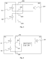
- Fig. 3 shows a schematically structural view of electronic equipment according to a first embodiment of the present invention.
- the electronic equipment comprises a mobile phone output end 100 and a speaker end 200.
- the speaker end 200 comprises a speaker body 201, an audio signal input terminal 202 connected with the speaker body 201, and a DC voltage signal input terminal 203 connected with the speaker body 201.
- the mobile phone output end 100 comprises an audio signal output circuit 101 and a DC voltage signal output circuit 102.
- the audio signal output circuit 101 is connected with the audio signal input terminal 202 to output an audio signal (an AC signal) to the speaker body 201.
- the DC voltage signal output circuit 102 is connected with the DC voltage signal input terminal 203 to output a DC voltage signal to the speaker body 201.
- the speaker body 201 further comprises a voice coil, and the DC voltage signal is applied to the voice coil.
- Fig. 4 shows a schematically structural view of the electronic equipment according to a second embodiment of the present invention.
- the second embodiment differs from the first embodiment in that the speaker end 200 further comprises a DC voltage signal modulation unit 204 connected with the speaker body 201 and the DC voltage signal input terminal 203, respectively.
- the DC voltage signal output from the DC voltage signal output circuit 102 is modulated by the DC voltage signal modulation unit 204, and then is output to the speaker body 201.
- modulation refers to the adjustment of a direction and strength of the DC voltage signal.
- the DC voltage signal output circuit 102 may be adjustable, such that different DC voltage signals can be set according to the actual testing conditions when the same mobile phone adopts different speakers.
- the present invention further provides a method for reducing a low frequency distortion degree of a speaker of electronic equipment, the method comprising the following steps: 1), outputting an audio signal and an adjustable DC voltage signal to the speaker; 2) testing distortion degrees of the speaker under different DC voltage signals; and 3) selecting the DC voltage signal under which the distortion degree is the lowest as a DC voltage signal output from the electronic equipment to the speaker.
- the present invention has the following benefits.
Landscapes
- Physics & Mathematics (AREA)
- Engineering & Computer Science (AREA)
- Acoustics & Sound (AREA)
- Signal Processing (AREA)
- Health & Medical Sciences (AREA)
- General Health & Medical Sciences (AREA)
- Otolaryngology (AREA)
- Amplifiers (AREA)
- Circuit For Audible Band Transducer (AREA)
- Telephone Function (AREA)
Abstract
Description
- The present invention relates to a speaker device, electronic equipment, and a method for reducing a low frequency distortion degree of a speaker of the electronic equipment.
- In a moving coil speaker, a position of a vibration system (including a voice coil and a vibration diaphragm) in a Z-axis direction determines a relative position between the vibration system and a magnetic circuit system, and this relative position affects symmetry between electromechanical coupling factors (BL) and equivalent paraelectric performance (Cms) of the whole system, affecting a vibration state of the system. As a displacement of the vibration system in a low frequency working condition is relatively large, influence of a relative position of the vibration system in the Z-axis under the low frequency on low frequency distortion of the speaker is significant.
- At present, due to precision constraints of manufacturing processes and materials, it is hard to reduce the distortion of the speaker in a low frequency condition to be lower than 10%. Or, even if lower distortion of the speaker is realized, it is difficult to guarantee the consistency between products. Therefore, it is necessary to provide a technical scheme that can reduce the low frequency distortion degree of the speaker.
- An object of the present invention is to provide a technical solution for reducing a low frequency distortion degree of a speaker.
- According to a first aspect of the present invention, there is provided a speaker device, comprising: a speaker body, an audio signal input terminal connected with the speaker body, and a direct current (DC) voltage signal input terminal connected with the speaker body.
- Optionally, the speaker device further comprises a DC voltage signal modulation unit connected with the speaker body and the DC voltage signal input terminal, respectively.
- Optionally, the speaker device comprises a voice coil, and a DC voltage signal is applied to the voice coil.
- According to a second aspect of the present invention, there is provided electronic equipment, comprising: the speaker device as described above, and a DC voltage signal output circuit connected with the DC voltage signal input terminal.
- Optionally, the DC voltage signal output circuit is an adjustable DC voltage signal output circuit.
- According to a third aspect of the present invention, there is provided a method for reducing a low frequency distortion degree of a speaker of electronic equipment, the method comprising the following steps: 1) outputting an audio signal and an adjustable DC voltage signal to the speaker; 2) testing distortion degrees of the speaker under different DC voltage signals; and 3) selecting the DC voltage signal under which the distortion degree is the lowest as a DC voltage signal output from the electronic equipment to the speaker.
- The present invention further provides a method for reducing a low frequency distortion degree of a speaker of electronic equipment, the method comprising the following steps: 1) providing a DC voltage signal modulation unit in the speaker; 2) outputting an audio signal and a fixed DC voltage signal to the speaker; 3) testing distortion degrees of the speaker under different modulation parameters of the DC voltage signal modulation unit; and 4) selecting the modulation parameter under which the distortion degree is the lowest as a modulation parameter of the DC voltage signal modulation unit, and controlling the electronic equipment to output the fixed DC voltage signal to the DC voltage signal modulation unit.
- The technical effect of the present invention is that low frequency distortion can be significantly improved by adding the DC voltage signal at the input end of the speaker, and moreover, the consistency between speaker products can be guaranteed.
- Further features of the present invention and advantages thereof will become apparent from the following detailed description of exemplary embodiments according to the present invention with reference to the attached drawings.
- The accompanying drawings, which are incorporated in and constitute a part of the specification, illustrate embodiments of the invention and, together with the description thereof, serve to explain the principles of the invention.
-
Fig. 1 shows a schematically structural view of existing electronic equipment and a speaker device. -
Fig. 2 is a THD curve comparison diagram showing before and after a DC voltage signal is provided in the present invention. -
Fig. 3 shows a schematically structural view of electronic equipment and a speaker device according to a first embodiment of the present invention. -
Fig. 4 shows a schematically structural view of the electronic equipment and the speaker device according to a second embodiment of the present invention. - Description of reference numerals: 100: mobile phone output end; 101: audio signal output circuit; 102: DC voltage signal output circuit; 200: speaker end; 201: speaker body; 202, audio signal input terminal; 203, DC voltage signal input terminal; and 204: DC voltage signal modulation unit.
- Various exemplary embodiments of the present invention will now be described in detail with reference to the drawings. It should be noted that the relative arrangement of the components and steps, the numerical expressions, and numerical values set forth in these embodiments do not limit the scope of the present invention unless it is specifically stated otherwise.
- The following description of at least one exemplary embodiment is merely illustrative in nature and is in no way intended to limit the invention, its application, or uses.
- Techniques, methods and apparatus as known by one of ordinary skill in the relevant art may not be discussed in detail but are intended to be part of the specification where appropriate.
- In all of the examples illustrated and discussed herein, any specific values should be interpreted to be illustrative only and non-limiting. Thus, other examples of the exemplary embodiments could have different values.
- Notice that similar reference numerals and letters refer to similar items in the following figures, and thus once an item is defined in one figure, it is possible that it need not be further discussed in the accompanying drawings.
- Referring to
Fig. 1 , an existing mobile phone is taken as an example. Parts related to a speaker in the mobile phone may be abstracted as a mobile phone output end 100 and aspeaker end 200. Thespeaker end 200 comprises aspeaker body 201 and an audiosignal input terminal 202 connected with thespeaker body 201. The mobilephone output end 100 comprises an audiosignal output circuit 101. The audiosignal output circuit 101 is connected with the audiosignal input terminal 202 to output an audio signal (an AC signal) to thespeaker body 201. - As shown in
Figs. 3 and 4 , the improvement of the present invention lies in that the input end of the speaker is additionally provided with a DC voltage bias signal. Referring to THD (Total Harmonic Distortion) curves shown inFig. 2 , the horizontal axis represents working frequencies of the speaker, the vertical axis represents distortion degrees, and a curve A is a previous THD curve of the speaker product. It can be seen that at a low frequency condition of 100 Hz-1,000 Hz, distortion degrees are larger, and a distortion peak value can be greater than 10%. After the DC voltage bias signal is additionally provided, a distortion situation is shown as a curve B. It can be seen that at the low frequency condition of 100 Hz-1,000 Hz, the distortion degrees are significantly reduced. -
Fig. 3 shows a schematically structural view of electronic equipment according to a first embodiment of the present invention. The electronic equipment comprises a mobilephone output end 100 and aspeaker end 200. Thespeaker end 200 comprises aspeaker body 201, an audiosignal input terminal 202 connected with thespeaker body 201, and a DC voltagesignal input terminal 203 connected with thespeaker body 201. The mobilephone output end 100 comprises an audiosignal output circuit 101 and a DC voltagesignal output circuit 102. The audiosignal output circuit 101 is connected with the audiosignal input terminal 202 to output an audio signal (an AC signal) to thespeaker body 201. The DC voltagesignal output circuit 102 is connected with the DC voltagesignal input terminal 203 to output a DC voltage signal to thespeaker body 201. Thespeaker body 201 further comprises a voice coil, and the DC voltage signal is applied to the voice coil. -
Fig. 4 shows a schematically structural view of the electronic equipment according to a second embodiment of the present invention. The second embodiment differs from the first embodiment in that thespeaker end 200 further comprises a DC voltage signal modulation unit 204 connected with thespeaker body 201 and the DC voltagesignal input terminal 203, respectively. The DC voltage signal output from the DC voltagesignal output circuit 102 is modulated by the DC voltage signal modulation unit 204, and then is output to thespeaker body 201. - Here, modulation refers to the adjustment of a direction and strength of the DC voltage signal.
- The DC voltage
signal output circuit 102 may be adjustable, such that different DC voltage signals can be set according to the actual testing conditions when the same mobile phone adopts different speakers. - With respect to individual electronic equipment and a speaker, it is of course desirable to precisely set the DC voltage signal to reduce the distortion degree to the greatest extent. Thus, the present invention further provides a method for reducing a low frequency distortion degree of a speaker of electronic equipment, the method comprising the following steps: 1), outputting an audio signal and an adjustable DC voltage signal to the speaker; 2) testing distortion degrees of the speaker under different DC voltage signals; and 3) selecting the DC voltage signal under which the distortion degree is the lowest as a DC voltage signal output from the electronic equipment to the speaker.
- It is available to arrange a DC voltage signal modulation unit in the speaker, and then, the following steps can be performed: 1) outputting an audio signal and a fixed DC voltage signal to the speaker; 2) testing distortion degrees of the speaker under different modulation parameters of the DC voltage signal modulation unit; and 3) selecting the modulation parameter under which the distortion degree is the lowest as a modulation parameter of the DC voltage signal modulation unit, and controlling the electronic equipment to output the fixed DC voltage signal to the DC voltage signal modulation unit.
- The present invention has the following benefits.
- 1. Through improvement, a lower distortion speaker in the prior art becomes an ultra-low distortion speaker.
- 2. The inconsistency of low frequency distortion of speakers, caused by mass production, is reduced.
- Although some specific embodiments of the present invention have been demonstrated in detail with examples, it should be understood by a person skilled in the art that the above examples are only intended to be illustrative but not to limit the scope of the present invention. It should be understood by those skilled in the art that the above embodiments can be modified without departing from the scope and spirit of the present invention. The scope of the present invention is defined by the appended claims.
Claims (7)
- A speaker device, comprising: a speaker body (201), an audio signal input terminal (202) connected with the speaker body (201), and a DC voltage signal input terminal (203) connected with the speaker body (201).
- The speaker device of claim 1, further comprising: a DC voltage signal modulation unit (204) connected with the speaker body (201) and the DC voltage signal input terminal (203), respectively.
- The speaker device of claim 1 or 2, further comprising: a voice coil, wherein a DC voltage signal is applied to the voice coil.
- An electronic equipment, comprising: the speaker device of claim 1 or 2, and a DC voltage signal output circuit (102) connected with the DC voltage signal input terminal (203).
- The electronic equipment of claim 4, wherein the DC voltage signal output circuit (102) is an adjustable DC voltage signal output circuit.
- A method for reducing a low frequency distortion degree of a speaker of electronic equipment, the method comprising the following steps: outputting an audio signal and an adjustable DC voltage signal to the speaker; testing distortion degrees of the speaker under different DC voltage signals; and selecting the DC voltage signal under which the distortion degree is the lowest as a DC voltage signal output from the electronic equipment to the speaker.
- A method for reducing a low frequency distortion degree of a speaker of electronic equipment, the method comprising the following steps: providing a DC voltage signal modulation unit in the speaker; outputting an audio signal and a fixed DC voltage signal to the speaker; testing distortion degrees of the speaker under different modulation parameters of the DC voltage signal modulation unit; and selecting the modulation parameter under which the distortion degree is the lowest as a modulation parameter of the DC voltage signal modulation unit, and controlling the electronic equipment to output the fixed DC voltage signal to the DC voltage signal modulation unit.
Applications Claiming Priority (2)
| Application Number | Priority Date | Filing Date | Title |
|---|---|---|---|
| CN201510172824.1A CN104918190A (en) | 2015-04-13 | 2015-04-13 | Loudspeaker device and method for reducing loudspeaker distortion problem |
| PCT/CN2015/094743 WO2016165322A1 (en) | 2015-04-13 | 2015-11-16 | Speaker device and method of reducing speaker distortion level |
Publications (2)
| Publication Number | Publication Date |
|---|---|
| EP3249951A1 true EP3249951A1 (en) | 2017-11-29 |
| EP3249951A4 EP3249951A4 (en) | 2018-03-14 |
Family
ID=54086815
Family Applications (1)
| Application Number | Title | Priority Date | Filing Date |
|---|---|---|---|
| EP15889018.6A Ceased EP3249951A4 (en) | 2015-04-13 | 2015-11-16 | Speaker device and method of reducing speaker distortion level |
Country Status (4)
| Country | Link |
|---|---|
| US (1) | US10063208B2 (en) |
| EP (1) | EP3249951A4 (en) |
| CN (1) | CN104918190A (en) |
| WO (1) | WO2016165322A1 (en) |
Families Citing this family (2)
| Publication number | Priority date | Publication date | Assignee | Title |
|---|---|---|---|---|
| CN104918190A (en) * | 2015-04-13 | 2015-09-16 | 歌尔声学股份有限公司 | Loudspeaker device and method for reducing loudspeaker distortion problem |
| CN112702687B (en) * | 2020-12-18 | 2022-10-11 | 厦门亿联网络技术股份有限公司 | Method for quickly confirming loudspeaker or complete machine distortion |
Family Cites Families (18)
| Publication number | Priority date | Publication date | Assignee | Title |
|---|---|---|---|---|
| US6914991B1 (en) * | 2000-04-17 | 2005-07-05 | Frank Joseph Pompei | Parametric audio amplifier system |
| US7443990B2 (en) * | 2004-11-01 | 2008-10-28 | Chattin Daniel A | Voltage biased capacitor circuit for a loudspeaker |
| JP2007088921A (en) * | 2005-09-22 | 2007-04-05 | Matsushita Electric Ind Co Ltd | Speaker protection circuit |
| CN1878431A (en) * | 2006-04-07 | 2006-12-13 | 张德忠 | High-fidelity wide band high-power flat loudspeaker |
| JP5058623B2 (en) * | 2007-02-16 | 2012-10-24 | キヤノン株式会社 | Speaker device, speaker driving device, and control method thereof |
| US9124219B2 (en) * | 2010-07-01 | 2015-09-01 | Conexant Systems, Inc. | Audio driver system and method |
| WO2012009670A2 (en) * | 2010-07-15 | 2012-01-19 | Conexant Systems, Inc. | Audio driver system and method |
| US9130527B2 (en) * | 2010-08-18 | 2015-09-08 | Dolby Laboratories Licensing Corporation | Method and system for controlling distortion in a critical frequency band of an audio signal |
| DE102011107721B4 (en) * | 2011-07-14 | 2014-02-13 | Ean Elektroschaltanlagen Gmbh | Method and device for measuring electrical currents using a current transformer |
| CN202285431U (en) * | 2011-09-30 | 2012-06-27 | 青岛海信移动通信技术股份有限公司 | Speaker protection circuit and mobile terminal |
| CN202330561U (en) * | 2011-09-30 | 2012-07-11 | 首瑞(北京)投资管理集团有限公司 | Direct current insulation monitoring device capable of compensating positive electrode grounding voltage excursion and negative electrode grounding voltage excursion |
| CN202406286U (en) * | 2011-11-18 | 2012-08-29 | 深圳市四季春科技有限公司 | Dual drive double balance radiation type loudspeaker |
| CN104170404B (en) * | 2012-03-05 | 2018-01-26 | 奥音科技(北京)有限公司 | Audio system, device with electro-acoustic transducer, measuring device and method |
| US9838794B2 (en) * | 2013-04-26 | 2017-12-05 | Sound Solutions International Co., Ltd. | Double coil speaker |
| US9332344B2 (en) * | 2013-06-13 | 2016-05-03 | Turtle Beach Corporation | Self-bias emitter circuit |
| CN104301847B (en) * | 2014-11-03 | 2017-11-28 | 常州阿木奇声学科技有限公司 | A kind of dynamic iron unit magnetic driving mechanism for reducing low-frequency distortion |
| CN104918190A (en) * | 2015-04-13 | 2015-09-16 | 歌尔声学股份有限公司 | Loudspeaker device and method for reducing loudspeaker distortion problem |
| CN204518066U (en) * | 2015-04-13 | 2015-07-29 | 歌尔声学股份有限公司 | A kind of speaker unit and a kind of electronic equipment |
-
2015
- 2015-04-13 CN CN201510172824.1A patent/CN104918190A/en active Pending
- 2015-11-16 WO PCT/CN2015/094743 patent/WO2016165322A1/en not_active Ceased
- 2015-11-16 US US15/551,244 patent/US10063208B2/en active Active
- 2015-11-16 EP EP15889018.6A patent/EP3249951A4/en not_active Ceased
Also Published As
| Publication number | Publication date |
|---|---|
| CN104918190A (en) | 2015-09-16 |
| EP3249951A4 (en) | 2018-03-14 |
| WO2016165322A1 (en) | 2016-10-20 |
| US10063208B2 (en) | 2018-08-28 |
| US20180026600A1 (en) | 2018-01-25 |
Similar Documents
| Publication | Publication Date | Title |
|---|---|---|
| DE102015121528B4 (en) | Method for controlling the diaphragm excursion of electrodynamic loudspeakers and devices therefor | |
| EP4525485A3 (en) | Bone conduction speaker and testing method therefor | |
| US9319777B2 (en) | Drive control circuit for vibration speaker | |
| US9955269B2 (en) | Microphone system with driven electrodes | |
| EP3041265A3 (en) | Loudspeaker with improved directional behavior and reduction of acoustical interference | |
| CN104780489B (en) | The double effect device that structure and acoustic-electric for detecting loudspeaker vibration displacement mutually turn | |
| US10951189B2 (en) | Signal processing device, method and speaker | |
| US20180167719A1 (en) | Speaker | |
| KR20190095498A (en) | Displacement limiter for loudspeaker mechanical protection | |
| US20180288526A1 (en) | Band-pass acoustic filter and acoustic sensing apparatus | |
| CN104869508A (en) | Electroacoustic conversion device | |
| JP5609883B2 (en) | Multi-band compressor and adjustment method | |
| EP3480950A1 (en) | Load detector | |
| EP2941012A3 (en) | Speaker system | |
| US10063208B2 (en) | Speaker device and method for reducing distortion degree of speaker | |
| CN106101932A (en) | A kind of loudspeaker audio drive circuit, method and intelligent terminal | |
| CN204518066U (en) | A kind of speaker unit and a kind of electronic equipment | |
| EP2874408B1 (en) | Loudspeaker polarity detector | |
| WO2016034777A3 (en) | An electrical power system and a method for controlling generator voltage | |
| DE102014101881A1 (en) | An audio output device and method for determining a speaker cone swing | |
| CN201134925Y (en) | electromagnetic speaker | |
| US9930446B2 (en) | Acoustic transducer | |
| CN104581492A (en) | Headset capable of producing ultrasonic waves and multimedia device with headset | |
| US9705464B2 (en) | Audio signal processing circuit | |
| US9264811B1 (en) | EQ correction for source device impedance and output device impedance interactions |
Legal Events
| Date | Code | Title | Description |
|---|---|---|---|
| PUAI | Public reference made under article 153(3) epc to a published international application that has entered the european phase |
Free format text: ORIGINAL CODE: 0009012 |
|
| 17P | Request for examination filed |
Effective date: 20170824 |
|
| AK | Designated contracting states |
Kind code of ref document: A1 Designated state(s): AL AT BE BG CH CY CZ DE DK EE ES FI FR GB GR HR HU IE IS IT LI LT LU LV MC MK MT NL NO PL PT RO RS SE SI SK SM TR |
|
| AX | Request for extension of the european patent |
Extension state: BA ME |
|
| A4 | Supplementary search report drawn up and despatched |
Effective date: 20180213 |
|
| RIC1 | Information provided on ipc code assigned before grant |
Ipc: H04R 9/04 20060101ALN20180207BHEP Ipc: H04R 29/00 20060101AFI20180207BHEP Ipc: H04R 3/08 20060101ALN20180207BHEP |
|
| 17Q | First examination report despatched |
Effective date: 20180417 |
|
| DAV | Request for validation of the european patent (deleted) | ||
| DAX | Request for extension of the european patent (deleted) | ||
| REG | Reference to a national code |
Ref country code: DE Ref legal event code: R003 |
|
| STAA | Information on the status of an ep patent application or granted ep patent |
Free format text: STATUS: THE APPLICATION HAS BEEN REFUSED |
|
| 18R | Application refused |
Effective date: 20200301 |