EP3249869A1 - Method and arrangement for adapting a multi-antenna transmission - Google Patents
Method and arrangement for adapting a multi-antenna transmission Download PDFInfo
- Publication number
- EP3249869A1 EP3249869A1 EP17179776.4A EP17179776A EP3249869A1 EP 3249869 A1 EP3249869 A1 EP 3249869A1 EP 17179776 A EP17179776 A EP 17179776A EP 3249869 A1 EP3249869 A1 EP 3249869A1
- Authority
- EP
- European Patent Office
- Prior art keywords
- matrix
- node
- precoding
- exp
- channel
- Prior art date
- Legal status (The legal status is an assumption and is not a legal conclusion. Google has not performed a legal analysis and makes no representation as to the accuracy of the status listed.)
- Granted
Links
Images


Classifications
-
- H—ELECTRICITY
- H04—ELECTRIC COMMUNICATION TECHNIQUE
- H04W—WIRELESS COMMUNICATION NETWORKS
- H04W24/00—Supervisory, monitoring or testing arrangements
- H04W24/02—Arrangements for optimising operational condition
-
- H—ELECTRICITY
- H04—ELECTRIC COMMUNICATION TECHNIQUE
- H04B—TRANSMISSION
- H04B7/00—Radio transmission systems, i.e. using radiation field
- H04B7/02—Diversity systems; Multi-antenna system, i.e. transmission or reception using multiple antennas
- H04B7/04—Diversity systems; Multi-antenna system, i.e. transmission or reception using multiple antennas using two or more spaced independent antennas
- H04B7/06—Diversity systems; Multi-antenna system, i.e. transmission or reception using multiple antennas using two or more spaced independent antennas at the transmitting station
-
- H—ELECTRICITY
- H04—ELECTRIC COMMUNICATION TECHNIQUE
- H04B—TRANSMISSION
- H04B1/00—Details of transmission systems, not covered by a single one of groups H04B3/00 - H04B13/00; Details of transmission systems not characterised by the medium used for transmission
- H04B1/69—Spread spectrum techniques
- H04B1/707—Spread spectrum techniques using direct sequence modulation
-
- H—ELECTRICITY
- H04—ELECTRIC COMMUNICATION TECHNIQUE
- H04B—TRANSMISSION
- H04B7/00—Radio transmission systems, i.e. using radiation field
- H04B7/02—Diversity systems; Multi-antenna system, i.e. transmission or reception using multiple antennas
- H04B7/04—Diversity systems; Multi-antenna system, i.e. transmission or reception using multiple antennas using two or more spaced independent antennas
- H04B7/0413—MIMO systems
- H04B7/0417—Feedback systems
-
- H—ELECTRICITY
- H04—ELECTRIC COMMUNICATION TECHNIQUE
- H04B—TRANSMISSION
- H04B7/00—Radio transmission systems, i.e. using radiation field
- H04B7/02—Diversity systems; Multi-antenna system, i.e. transmission or reception using multiple antennas
- H04B7/04—Diversity systems; Multi-antenna system, i.e. transmission or reception using multiple antennas using two or more spaced independent antennas
- H04B7/0413—MIMO systems
- H04B7/0456—Selection of precoding matrices or codebooks, e.g. using matrices antenna weighting
- H04B7/046—Selection of precoding matrices or codebooks, e.g. using matrices antenna weighting taking physical layer constraints into account
- H04B7/0465—Selection of precoding matrices or codebooks, e.g. using matrices antenna weighting taking physical layer constraints into account taking power constraints at power amplifier or emission constraints, e.g. constant modulus, into account
-
- H—ELECTRICITY
- H04—ELECTRIC COMMUNICATION TECHNIQUE
- H04B—TRANSMISSION
- H04B7/00—Radio transmission systems, i.e. using radiation field
- H04B7/02—Diversity systems; Multi-antenna system, i.e. transmission or reception using multiple antennas
- H04B7/04—Diversity systems; Multi-antenna system, i.e. transmission or reception using multiple antennas using two or more spaced independent antennas
- H04B7/0413—MIMO systems
- H04B7/0456—Selection of precoding matrices or codebooks, e.g. using matrices antenna weighting
- H04B7/046—Selection of precoding matrices or codebooks, e.g. using matrices antenna weighting taking physical layer constraints into account
- H04B7/0469—Selection of precoding matrices or codebooks, e.g. using matrices antenna weighting taking physical layer constraints into account taking special antenna structures, e.g. cross polarized antennas into account
-
- H—ELECTRICITY
- H04—ELECTRIC COMMUNICATION TECHNIQUE
- H04B—TRANSMISSION
- H04B7/00—Radio transmission systems, i.e. using radiation field
- H04B7/02—Diversity systems; Multi-antenna system, i.e. transmission or reception using multiple antennas
- H04B7/04—Diversity systems; Multi-antenna system, i.e. transmission or reception using multiple antennas using two or more spaced independent antennas
- H04B7/06—Diversity systems; Multi-antenna system, i.e. transmission or reception using multiple antennas using two or more spaced independent antennas at the transmitting station
- H04B7/0613—Diversity systems; Multi-antenna system, i.e. transmission or reception using multiple antennas using two or more spaced independent antennas at the transmitting station using simultaneous transmission
- H04B7/0615—Diversity systems; Multi-antenna system, i.e. transmission or reception using multiple antennas using two or more spaced independent antennas at the transmitting station using simultaneous transmission of weighted versions of same signal
- H04B7/0619—Diversity systems; Multi-antenna system, i.e. transmission or reception using multiple antennas using two or more spaced independent antennas at the transmitting station using simultaneous transmission of weighted versions of same signal using feedback from receiving side
- H04B7/0636—Feedback format
- H04B7/0639—Using selective indices, e.g. of a codebook, e.g. pre-distortion matrix index [PMI] or for beam selection
-
- H—ELECTRICITY
- H04—ELECTRIC COMMUNICATION TECHNIQUE
- H04B—TRANSMISSION
- H04B7/00—Radio transmission systems, i.e. using radiation field
- H04B7/02—Diversity systems; Multi-antenna system, i.e. transmission or reception using multiple antennas
- H04B7/04—Diversity systems; Multi-antenna system, i.e. transmission or reception using multiple antennas using two or more spaced independent antennas
- H04B7/06—Diversity systems; Multi-antenna system, i.e. transmission or reception using multiple antennas using two or more spaced independent antennas at the transmitting station
- H04B7/0697—Diversity systems; Multi-antenna system, i.e. transmission or reception using multiple antennas using two or more spaced independent antennas at the transmitting station using spatial multiplexing
-
- H—ELECTRICITY
- H04—ELECTRIC COMMUNICATION TECHNIQUE
- H04B—TRANSMISSION
- H04B7/00—Radio transmission systems, i.e. using radiation field
- H04B7/02—Diversity systems; Multi-antenna system, i.e. transmission or reception using multiple antennas
- H04B7/04—Diversity systems; Multi-antenna system, i.e. transmission or reception using multiple antennas using two or more spaced independent antennas
- H04B7/08—Diversity systems; Multi-antenna system, i.e. transmission or reception using multiple antennas using two or more spaced independent antennas at the receiving station
-
- H—ELECTRICITY
- H04—ELECTRIC COMMUNICATION TECHNIQUE
- H04J—MULTIPLEX COMMUNICATION
- H04J11/00—Orthogonal multiplex systems, e.g. using WALSH codes
-
- H—ELECTRICITY
- H04—ELECTRIC COMMUNICATION TECHNIQUE
- H04L—TRANSMISSION OF DIGITAL INFORMATION, e.g. TELEGRAPHIC COMMUNICATION
- H04L25/00—Baseband systems
- H04L25/02—Details ; arrangements for supplying electrical power along data transmission lines
- H04L25/03—Shaping networks in transmitter or receiver, e.g. adaptive shaping networks
- H04L25/03006—Arrangements for removing intersymbol interference
- H04L25/03343—Arrangements at the transmitter end
-
- H—ELECTRICITY
- H04—ELECTRIC COMMUNICATION TECHNIQUE
- H04W—WIRELESS COMMUNICATION NETWORKS
- H04W72/00—Local resource management
- H04W72/04—Wireless resource allocation
- H04W72/044—Wireless resource allocation based on the type of the allocated resource
- H04W72/0446—Resources in time domain, e.g. slots or frames
-
- H—ELECTRICITY
- H04—ELECTRIC COMMUNICATION TECHNIQUE
- H04B—TRANSMISSION
- H04B7/00—Radio transmission systems, i.e. using radiation field
- H04B7/02—Diversity systems; Multi-antenna system, i.e. transmission or reception using multiple antennas
- H04B7/10—Polarisation diversity; Directional diversity
-
- H—ELECTRICITY
- H04—ELECTRIC COMMUNICATION TECHNIQUE
- H04L—TRANSMISSION OF DIGITAL INFORMATION, e.g. TELEGRAPHIC COMMUNICATION
- H04L25/00—Baseband systems
- H04L25/02—Details ; arrangements for supplying electrical power along data transmission lines
- H04L25/03—Shaping networks in transmitter or receiver, e.g. adaptive shaping networks
- H04L25/03006—Arrangements for removing intersymbol interference
- H04L2025/0335—Arrangements for removing intersymbol interference characterised by the type of transmission
- H04L2025/03426—Arrangements for removing intersymbol interference characterised by the type of transmission transmission using multiple-input and multiple-output channels
-
- H—ELECTRICITY
- H04—ELECTRIC COMMUNICATION TECHNIQUE
- H04W—WIRELESS COMMUNICATION NETWORKS
- H04W88/00—Devices specially adapted for wireless communication networks, e.g. terminals, base stations or access point devices
- H04W88/02—Terminal devices
-
- H—ELECTRICITY
- H04—ELECTRIC COMMUNICATION TECHNIQUE
- H04W—WIRELESS COMMUNICATION NETWORKS
- H04W88/00—Devices specially adapted for wireless communication networks, e.g. terminals, base stations or access point devices
- H04W88/08—Access point devices
Definitions
- the present invention relates to a method and an arrangement in a first node and a method and an arrangement in a second node.
- it relates to adaptation of a multi-antenna transmission from the first node to the second node over a wireless channel.
- MIMO Multiple Input Multiple Output
- TTI Transmission Time Interval
- Precoding is another related form of adaptation where the phases and amplitudes of the aforementioned signals are adjusted to better fit the current channel properties.
- Classical beam-forming is a special case of precoding in which the phase of an information-carrying signal is adjusted on each transmit antenna so that all the transmitted signals add constructively at the receiver.
- the signals form a vector-valued signal and the adjustment may be thought of as multiplication by a precoder matrix.
- the precoder matrix is chosen based on information about the channel properties. A common approach is to select the precoder matrix from a finite and countable set, a so-called codebook.
- codebook based precoding is an integral part of the Long Term Evolution (LTE) standard and will be supported in MIMO for High Speed Downlink Packet Access (HSDPA) in Wideband Code Division Multiple Access (WCDMA) as well.
- the receiver e.g. User Equipment, UE
- the transmitter would then use the signalled information, when deciding which precoder matrix to apply. Since codebook indices need to be signalled and the receiver needs to select a suitable codebook element, it is important to keep the codebook size as small as possible. On the other hand, larger codebooks ensure that it is possible to find an entry that matches the current channel conditions more closely.
- Codebook based precoding may be seen as a form of channel quantization. Alternatively, methods may be used that compute the precoder matrix without resorting to quantization.
- precoder codebook design The fundamental goal of precoder codebook design is to keep the codebook size small while still achieving as high performance as possible. Design of the elements in the codebook thus becomes crucial in order to achieve the intended performance.
- PA Power Amplifiers
- the objective problem is to provide a mechanism for improving the performance of a wireless channel when using precoding.
- the object is achieved by a method in a first node for adapting a multi-antenna transmission to a second node over a wireless channel.
- the wireless channel has at least three inputs and at least one output.
- the first node and the second node are comprised in a wireless communication system.
- the method comprises the steps of obtaining at least one symbol stream, and determining a precoding matrix having a product structure created by a block diagonal matrix being multiplied from the left with a block diagonalizing unitary matrix.
- the method comprises the further steps of precoding the at least one symbol stream with the determined precoding matrix, and transmitting the precoded at least one symbol stream over a wireless channel to the second node.
- the object is achieved by a method in a second node for receiving a multi-antenna transmission from a first node over a wireless channel.
- the wireless channel has at least three inputs and at least one output.
- the first node and the second node are comprised in a wireless communication system.
- the method comprises the step of receiving a transmission corresponding to at least one symbol stream over a wireless channel conveyed from the first node.
- the at least one symbol stream is precoded with a precoding matrix having a product structure created by a block diagonal matrix being multiplied from the left with a block diagonalizing unitary matrix.
- the object is achieved by an arrangement in a first node for adapting a multi-antenna transmission to a second node over a wireless channel.
- the wireless channel has at least three inputs and at least one output.
- the first node and the second node are comprised in a wireless communication system.
- the first node arrangement comprises an obtaining unit configured to obtain at least one symbol stream, and a determining unit configured to determine a precoding matrix having a product structure created by a block diagonal matrix being multiplied from the left with a block diagonalizing unitary matrix.
- the first node arrangement further comprises precoding unit configured to precode the at least one symbol stream with the determined precoding matrix, and a transmitting unit configured to transmit the precoded at least one symbol stream over a wireless channel to the second node.
- the object is achieved by an arrangement in a second node for receiving a multi-antenna transmission from a first node over a wireless channel.
- the wireless channel having at least three inputs and at least one output.
- the first node and the second node are comprised in a wireless communication system.
- the second node arrangement comprises a receiving unit configured to receive a transmission corresponding to at least one symbol stream over a wireless channel conveyed from the first node.
- the at least one symbol stream is precoded with a precoding matrix having a product structure created by a block diagonal matrix being multiplied from the left with a block diagonalizing unitary matrix.
- a precoding matrix having a product structure is used.
- the precoding matrix having a product structure is created by a block diagonal matrix being multiplied with a block diagonalizing unitary matrix.
- This matrix having a product structure for precoding a symbol stream when transmitting it over a wireless link helps balancing the PAs. This implies that more power can be emitted into the propagation channel resulting in an improved performance of the wireless channel.
- An advantage with the present solution is that using the matrix having a product structure, improves performance by e.g. allowing higher data rates or better reliability, particularly when the polarizations are not perfectly separated (e.g. moderate cross polar discrimination (XPD)) when used in conjunction with +-45 degree polarized arrays.
- the use of the PAs is also optimized thus reducing the power consumption as well as heat dissipation.
- the invention is defined as a method and an arrangement in a respective first and second node, which may be put into practice in the embodiments described below.
- FIG. 1 depicts a first node 100 in a wireless communication system 110.
- the wireless communication system 110 may be a cellular system and/or a system such as e.g. Long Term Evolution (LTE), Evolved - Universal Terrestrial Radio Access (E-UTRA), Worldwide Interoperability for Microwave Access (WiMAX), Universal Terrestrial Radio Access (UTRA), Wideband Code Division Multiple Access (WCDMA), GSM, Ultra Mobile Wideband (UMB) or any other wireless communication system using technologies that perform adaptation between different forms of transmission and use multiple antennas.
- LTE Long Term Evolution
- E-UTRA Evolved - Universal Terrestrial Radio Access
- WiMAX Worldwide Interoperability for Microwave Access
- UTRA Universal Terrestrial Radio Access
- WCDMA Wideband Code Division Multiple Access
- GSM Global System for Mobile Communications
- UMB Ultra Mobile Wideband
- a linear and time-invariant MIMO filter may be used to model the input-output relation of the wireless channel during a sufficiently short transmission period.
- a single matrix may be used for describing the filter.
- Such a channel matrix description also holds for modelling the channel over a subcarrier, (or several subcarriers as long they span a bandwidth which is small compared with the coherence bandwidth of the channel) in an Orthogonal Frequency Division Multiplexing (OFDM) system such as e.g. LTE.
- OFDM Orthogonal Frequency Division Multiplexing
- the first node 100 may be any type of a base station such as e.g. a NodeB as in LTE.
- the second node 120 may be a user equipment (UE) such as e.g.
- the first node 100 may be a UE such as e.g. a mobile phone, a Personal Digital Assistant (PDA) and the second node 120 may be any type of a base station such as e.g. a NodeB.
- the first node 100 is a base station and the second node 120 is a user equipment.
- the first node 100 and the second node 120 may constitute arbitrary wireless devices in communication with each other and with no particular hierarchical ordering.
- the first node 100 uses a multiple antenna system, i.e. uses multiple antennas for its transmission to the second node 120.
- the second node 120 may also use a multiple antenna system for reception of the first node's transmission.
- This is thus a MIMO system, where the inputs to the channel corresponds to the transmit antennas in the first node 100 and the outputs to the receive antennas in the second node 120.
- Transmitter and receiver filtering/processing may also be considered to be included into the channel. Note that such a MIMO setup may include the special case of only one receive antenna.
- Figure 2 illustrates some embodiments wherein the first node 100 and a second node 120 are each using a multiple antenna system comprising four antennas.
- the first node 100 obtains an information carrying signal 140 being represented by a sequence of information bits, which information is to be conveyed to the second node 120 over the wireless channel 130.
- Figure 2 schematically illustrates the first node 100 as being the transmitting node (Tx) and the second node 120 as being the receiving node (Rx), the first node 100 and the second node 120 may use a multiple-antenna system 150, resulting in a MIMO link.
- the first node 100 comprises four transmit antennas 160 1, 2, 3 and 4, e.g. a base station with four transmit antennas
- the second node 120 comprises four receive antennas 170 1, 2, 3 and 4, e.g. a user equipment with four receive antennas.
- the first node 100 comprises an encoding unit 162, a post precoding unit 163 and four radio transmitter units 164.
- the encoding unit 162 is arranged to receive the information carrying signal 140 to be transmitted.
- the encoding unit 162 may further be arranged to possibly demultiplex the information bits into one or several information bit sequences, code these information bit sequences using some channel code (e.g. turbo code, low-density parity-check (LDPC) code, convolutional code), modulate the coded bits to produce symbols, map the symbols to a sequence of information carrying symbol vectors and precode the information carrying symbol vectors and finally forward the result to a possible post precoding unit 163.
- channel code e.g. turbo code, low-density parity-check (LDPC) code, convolutional code
- the post-precoding unit 163 may in the simplest of cases just forward the precoded signal (i.e., the post precoding unit 163 is transparent and would hence be viewed as not existing) or it might process it in some way, e.g. perform digital filtering in baseband, before outputting possibly processed signals for transmission utilizing the radio transmitter units 164, using the respective transmit antennas 160 1, 2, 3 and 4 for transmitting the precoded signal to the second node 120.
- the transmitter in this example may support techniques such as Spatial-Division Multiple Access (SDMA), SDMA precoding, MIMO, MIMO precoding, and/or MIMO-SDMA.
- SDMA Spatial-Division Multiple Access
- MIMO MIMO precoding
- MIMO-SDMA MIMO-SDMA
- the second node 120 comprises a pre-processing unit 171, a decoding demodulation unit 172 and four radio receiver units 174.
- the second node 120 is arranged to receive the precoded signal from the first node 100. The signal is received by means of the receive antennas 170 1, 2, 3 and 4, the pre-processing unit 171 and the radio receiver units 174.
- the pre-processing unit 171 may implement various processing steps, e.g. it may perform filtering in base band or simply forward the signals unaltered to the decoding demodulation unit 172. In the latter case, the pre-processing unit 171 may alternatively be considered not to be present (i.e., transparent corresponding to no pre-processing unit).
- the decoding demodulation unit 172 may be arranged to receive the coded signal from the pre-processing unit 171.
- the decoding demodulation unit 172 may further be arranged to demodulate the coded signal to data bits. It is appreciated that the basic functions of the receiver are well known for a skilled person and not described in detail herein.
- both receiver in the second node 120 and transmitter in the first node 100 may alter operation mode functioning as transmitter and receive, respectively.
- the encoding unit 162 in the first node 100 can be further subdivided into two parts, corresponding to a coding and modulation unit 300 and a precoding unit 310, such as e.g. a precoder.
- a coding and modulation unit 300 and a precoding unit 310 is depicted in Figure 3 .
- the coding and modulation unit 300 takes information bits as input and produces a sequence of information carrying symbol vectors, i.e. a vector-valued information-carrying signal as output.
- the information carrying symbol vectors can be seen as one or several symbol streams in parallel where each element of each vector s thus belongs to a certain symbol stream.
- the different symbol streams are commonly referred to as layers and at any given moment there are r different such layers corresponding to a transmission rank of r.
- the signal to be transmitted to the second node 120 over the wireless channel 130 comprises at least one symbol stream (or layer).
- the r symbols in a particular r ⁇ 1 information carrying symbol vector s is subsequently multiplied by an N T ⁇ r precoder matrix W N T ⁇ r .
- N T denotes the number of inputs (e.g. number of transmit antennas, number of antenna ports etc) of the MIMO channel.
- the mentioned precoding operation forwards the resulting output to the post-processing unit 163.
- the first node 100 determines a precoding matrix having a certain product structure, which will be further described in the sequel.
- This may be performed by choosing a precoding matrix to match the characteristics of the channel, i.e., to match an N R ⁇ N T MIMO channel matrix H.
- the precoder matrix W N T ⁇ r may thus depend on the value of the channel H.
- the r information carrying symbols in s are typically complex-valued. Support of rank adaptation allows the number of simultaneously transmitted symbol streams, r, to be set to suit the current channel characteristics.
- the signals are conveyed over the channel H and received by an antenna array with N R elements.
- the receiver possibly processes the signals by means of the pre-processing unit 171.
- the first node 100 comprises a multi-antenna system where in some embodiments at least one antenna emits radio waves in a horizontal polarization direction and at least one other antenna emits energy in the orthogonal (i.e., vertical) polarization direction.
- a dual-, or cross-, polarized antenna setup may thus contain a group of co-polarized antennas and another group of co-polarized antennas orthogonally polarized relative the former group.
- "Co-polarization" means the antennas are transmitting with the same polarization.
- the cross-polarized antenna set-up results in a block diagonal channel matrix, which will be further explained below.
- the first two transmit antennas 160, 1 and 2 are horizontally polarized and the remaining two, 3 and 4, are vertically polarized.
- the receive antennas in the second node 120 are similarly arranged.
- the co-polarized antennas in the transmit array may be spaced sufficiently far apart so that the fading is roughly uncorrelated among the channels associated with the co-polarized elements.
- the channel may be modelled using a channel matrix.
- signals transmitted on antennas 160 1 and 2 in the first node 100 do not reach receive antennas 170 3 and 4, and, correspondingly, signals from transmit antennas 160 3 and 4 do not reach receive antennas 170 1 and 2.
- the complex-valued channel coefficient h 11 represents the effective channel involving the physical channel between transmit antenna 160 1 and receive antenna 170
- the complex-valued channel coefficient h 12 represents the effective channel involving the physical channel between transmit antenna 160 2 and receive antenna 170 1
- the complex-valued channel coefficient h 21 represents the effective channel involving the physical channel between transmit antenna 160 1 and receive antenna 170 2
- the complex-valued channel coefficient h 22 represents the effective channel involving the physical channel between transmit antenna 160 2 and receive antenna 170 2.
- the complex-valued channel coefficient h 33 represents the effective channel involving the physical channel between transmit antenna 160 3 and receive antenna 170 3
- the complex-valued channel coefficient h 34 represents the effective channel involving the physical channel between transmit antenna 160 4 and receive antenna 170 3
- the complex-valued channel coefficient h 43 represents the effective channel involving the physical channel between transmit antenna 160 3 and receive antenna 170 4
- the complex-valued channel coefficient h 44 represents the effective channel involving the physical channel between transmit antenna 160 4 and receive antenna 170 4.
- the channel is defined to be block diagonal if it can be rearranged by means of appropriate row and column permutations to have a form as above such that the average powers (as averaged over sufficiently long time-period so that the fast fading is averaged out) of the channel coefficients in the off-diagonal blocks Z M ⁇ 1 ⁇ L ⁇ 2 are significantly lower than the average powers of the channel coefficients in the on-diagonal blocks H M ⁇ k ⁇ L ⁇ k k .
- Such significantly lower power would e.g occur if a cross-polarized antenna setup is used in the first node 100 and a similar cross-polarized antenna setup is used in the second node 120.
- the difference in average power between channel coefficients on the block diagonal and off the block diagonal is often, depending on the propagation scenario, around 6 dB or substantially higher. Even if the antenna setup used in the second node 120 is not exactly cross-polarized, the power differences may still be significant.
- Precoding matrix having a product structure.
- the first node 100 determines a precoding matrix having a certain product structure.
- the notion of a product structure will be presented later and explicitly defined after the discussion on precoding and codebooks for precoding.
- the determined precoding matrix is to be used for precoding the at least one symbol stream (i.e., one or more layers) to be transmitted to the second node 120.
- the determination may be performed by choosing the precoding matrix to match the characteristics of the channel modelled using the channel matrix H. If the cross-polarized antenna setup at the first node 100 is using horizontal and vertically polarized antennas, a precoding with block diagonal structure is suitable since the use of a block diagonal structure precoder matches the block diagonal structure of the block diagonal channel matrix.
- the channel matrix is no longer likely to be as block diagonal as if horizontal and vertical polarizations would have been used.
- the precoder product structure is in this case beneficial since it involves decomposing the precoder into a product of two matrices, one unitary, so-called block diagonalizing unitary matrix, and one block diagonal matrix, where the latter matrix is multiplied from the left with the former.
- the block diagonalizing unitary matrix determined to be used allows the +-45 degree cross-polarized antenna setup to be transformed into a virtual 0/90 degree cross-polarized antenna setup (i.e., horizontally and vertically polarized), which in turn sees a new resulting channel that has a tendency to be block diagonal. Since a block diagonal virtual channel is effectively obtained, the block diagonal precoder in the product structure can now be used to match its characteristics. Basically, the unitary matrix serves to rotate the polarizations so that the transmitted signals align with the vertical and horizontal directions. A benefit of such a product structure is that the precoders can be made to have constant modulus elements meaning that regardless of which exact product structure precoder is used, the same power is used on all the antenna ports.
- the product structure not only aligns the transmission in the beneficial horizontal and vertical polarizations but is also at the same time offering pooling of the PA powers between these two polarizations.
- the first node 100 comprises a codebook 180.
- the first node 100 may perform the determination of the precoding matrix having a certain product structure by selecting the precoding matrix having a product structure from the codebook 180 comprised in the first node 100.
- the second node 120 comprises a code book 190 as shown in Figure 2 .
- the second node 120 may select a precoding matrix from e.g. the codebook 190 and recommend the first node to use the selected precoding matrix. This may be performed by conveying the recommended precoding matrix to the first node 100. The first node 100 may then decide to use the recommended precoding matrix or exploit the provided channel information in some other way.
- the codebook 180, 190 comprises precoding matrices where each precoding matrix may correspond to different multiple transmission modes or forms of spatial processing, e.g., channel dependent precoding, MIMO precoding, SDMA, SDMA with precoding, MIMO-SDMA, etc. Such information may be pre-defined.
- the codebook 180, 190 may further in addition to precoder matrices/vectors comprise many other parameters such as, transmission ranks, modulation choices, transport block sizes, powers and/or channelization codes etc.
- the codebook 180, 190 comprises a precoder where the transmission rank is implicitly given by the size of the precoder matrix.
- the codebook 180, 190 is suitable for an antenna setup at the first node with not necessarily 0/90 degree polarizations in that the codebook 180, 190 comprises one or more precoding matrices having said product structure.
- the codebook 180, 190 may further comprise precoding matrices having a non-product structure.
- the first node 100 or second node 120 is free to select a precoding matrix having said product structure from the codebook.
- the codebooks 180 and 190 may be known a priori by both the first node 100 and the second node 120. Also, the transmitter in the first node 100 may, for example, notify the receiver in the second node 120 of its codebook 180.
- a suitable codebook structure will also have a product structure in the meaning that a significant number of the precoder elements use the product structure.
- the block diagonal characteristic of W pertains to the placement of zeros in the precoder matrices.
- a precoder matrix is considered block diagonal if its columns and rows can be permuted so as to achieve the above form.
- a block may be of size 1 x1.
- the identity matrix can also be considered to have a block diagonal structure.
- the transmission can be viewed as coming from a block diagonal codebook applied to an antenna setup with vertically and horizontally polarized antennas.
- the codebook of precoder elements in Table 2 is obtained.
- Table 1 Example of a set of block diagonal W ⁇ matrices suitable especially well for two spatially separated (small distance) cross polarized antenna pairs in SU-MIMO mode.
- the codebook in Table 2 works fine as long as the two polarizations are well-separated, i.e., if the cross-polar discrimination (XPD) is sufficiently high.
- XPD cross-polar discrimination
- the problem is then that even multiplying with the above V matrix leads to power imbalances among the PAs. In other words, not all elements in each precoder matrix/vector multiplication have the same magnitude.
- V exp j ⁇ / 4 0 exp ⁇ j ⁇ / 4 0 0 exp j ⁇ / 4 0 exp ⁇ j ⁇ / 4 exp j ⁇ / 4 0 ⁇ exp ⁇ j ⁇ / 4 0 0 exp j ⁇ / 4 0 ⁇ exp ⁇ j ⁇ / 4 .
- the codebooks and the above unitary matrices can easily be generalized to other transmit array sizes (i.e., other than four antennas) and it is also possible to multiply the precoder elements from the right with some possibly unitary matrix or matrices and additional matrix multiplications from the left as well. This includes permuting the rows and/or columns of the precoder elements. These codebooks can also be subsets of larger codebooks. In conjunction to this, it should be noted that there are many equivalent ways of expressing the above product structure, in particular for the block diagonalizing unitary matrix V.
- a block diagonalizing unitary matrix is defined to mean a unitary (unitary up to a scaling factor) matrix such that for a particular cross-polarized antenna setup, it creates a virtual cross-polarized antenna setup which mimics the transmission from a cross-polarized antenna setup with vertically and horizontally polarized antennas, which at the same time ensures that together with the block diagonal matrices in the product structure, all scalar elements of the resulting product structure precoder matrices have the same absolute value.
- the block diagonalizing unitary matrix rotates the polarizations in said manner and ensures that the use of the PAs is balanced.
- a 45 degree block diagonalizing unitary matrix is defined to mean a block diagonalizing unitary matrix that rotates the polarization directions 45 degrees.
- Table 3 Example structure of set of W ⁇ matrices suitable especially well for two spatially separated (small distance) cross polarized antenna pairs in SU-MIMO mode. Note that for rotational simplicity, the scaling of the matrices so as to keep the total transmit power constant regardless of selected precoding matrix has intentionally been left out.
- the wireless channel 130 has at least three inputs and at least one output.
- the first node 100 and the second node 120 are comprised in the wireless communication system 110. The method comprising the steps of:
- the first node 100 comprises an arrangement 500 depicted in Figure 5 .
- the first node 100 and the second node 120 are comprised in the wireless communication system 110.
- the first node arrangement is arranged to adapt a multi-antenna transmission to a second node 120 over a wireless channel.
- the wireless channel 130 has at least three inputs and at least one output.
- the first node 100 and the second node 120 are comprised in the wireless communication system 110.
- the first node arrangement 500 comprises an obtaining unit 510 configured to obtain at least one symbol stream.
- the first node arrangement 500 further comprises a determining unit 520 configured to determine a precoding matrix having a product structure created by a block diagonal matrix being multiplied from the left, with a block diagonalizing unitary matrix.
- the block diagonalizing unitary matrix is a 45 degree block diagonalizing unitary matrix.
- the determining unit 520 may further be configured to determine the precoding matrix by basing the determination on measurements on a reverse link and/or exploiting channel reciprocity properties.
- the block diagonalizing unitary matrix may be equivalent to 1 0 1 0 0 1 0 1 1 0 ⁇ 1 0 0 1 0 ⁇ 1 or exp j ⁇ / 4 0 exp ⁇ j ⁇ / 4 0 0 exp j ⁇ / 4 0 exp ⁇ j ⁇ / 4 exp j ⁇ / 4 0 ⁇ exp ⁇ j ⁇ / 4 0 0 exp j ⁇ / 4 0 ⁇ exp ⁇ j ⁇ / 4 0 ⁇ exp ⁇ j ⁇ / 4 0 ⁇ exp ⁇ j ⁇ / 4 .
- the first node arrangement 500 further comprises a precoding unit 530 configured to precode the at least one symbol stream with the determined precoding matrix.
- the first node arrangement 500 further comprises a transmitting unit 540 configured to transmit the precoded at least one symbol stream over a wireless channel 130 to the second node 120.
- the first node arrangement 500 comprises a precoding codebook 180.
- the precoding codebook 180 may comprise precoding elements, wherein at least half of the precoding elements in the precoding codebook 180 have said product structure.
- the determining unit 520 may be configured to select the precoding matrix having a product structure from the precoding codebook 180.
- the first node arrangement 500 comprises a receiving unit 550 configured to receive channel information from the second node 120.
- the determining unit 520 may be configured to determine the precoding matrix based on the channel information received from the second node 120.
- the channel information may comprise a precoding matrix that the second node 120 recommends the first node 100 to use for the precoding.
- the channel information comprises a channel estimate.
- the first node arrangement 500 may further comprise a multi-antenna system with a cross-polarized antenna set-up.
- the transmitting unit 540 may be configured to transmit the precoded at least one symbol stream in the first node 100 using said multi-antenna.
- the wireless channel 130 has at least three inputs and at least one output.
- the first node 100 and the second node 120 are comprised in a wireless communication system 110.
- the method comprising the step of:
- the second node 120 comprises an arrangement 700 depicted in Figure 7 .
- the second node 120 is arranged to receive a multi-antenna transmission from a first node 100 over a wireless channel 130.
- the wireless channel has at least three inputs and at least one output.
- the first node 100 and the second node 120 are comprised in a wireless communication system 110.
- the second node arrangement 700 comprises a receiving unit 710 configured to receive a transmission corresponding to at least one symbol stream over a wireless channel 130 conveyed from the first node 100.
- the at least one symbol stream is precoded with a precoding matrix having a product structure created by a block diagonal matrix being multiplied from the left with a block diagonalizing unitary matrix.
- the block diagonalizing unitary matrix is a 45 degree block diagonalizing unitary matrix.
- the precoding matrix may be comprised in a precoding codebook 180, 190 of finite size wherein at least half of the precoding elements in the precoding codebook have said product structure.
- the precoding codebook 180, 190 may be comprised in the first node 100 or the second node 120.
- the block diagonalizing unitary matrix may e.g. be equivalent to 1 0 1 0 0 1 0 1 1 0 ⁇ 1 0 0 1 0 ⁇ 1 or exp j ⁇ / 4 0 exp ⁇ j ⁇ / 4 0 0 exp j ⁇ / 4 0 exp ⁇ j ⁇ / 4 exp j ⁇ / 4 0 ⁇ exp ⁇ j ⁇ / 4 0 0 exp j ⁇ / 4 0 ⁇ exp ⁇ j ⁇ / 4 0 ⁇ exp ⁇ j ⁇ / 4 0 ⁇ exp ⁇ j ⁇ / 4 .
- the second node arrangement 700 further comprises a conveying unit 720 configured to convey channel information to the first node 100.
- the channel information may be used by the first node 100 as base for determining the precoding matrix with which the received at least one symbol stream will be precoded.
- the channel information arranged to be conveyed comprises a channel estimate.
- the second node arrangement 700 may further comprise a selecting unit 730 configured to select the precoding matrix to be recommended to be used by the first node 100 for precoding said transmission.
- the channel information arranged to be conveyed by the conveying unit 720 to the first node 100 may be represented by the selected and recommended precoding matrix.
- the precoding codebook 190 is comprised in the second node 120.
- the recommended precoding matrix may be selected out of said precoding codebook 180, 190.
- the second node arrangement 700 further comprises a multi-antenna system with a cross-polarized antenna setup.
- the receiving unit 710 further may be configured to receive said transmission of the precoded at least one symbol stream by using said multi-antenna system.
- Some embodiments of the present method may be described as a method for enhancing performance in a wireless communication environment, comprising: modifying a pre-coding scheme by multiplying one or several of: codebook pre-coder elements, a transmitted signal, or parts thereof, before or after possible pilots, with certain unitary matrices and extending a block diagonal codebook with non-block diagonal elements.
- Non-block diagonal elements may be added to the block diagonal codebook to improve performance where cross polar discrimination is not infinite.
- All the elements in said codebook may be multiplied with a unitary matrix to transform a ⁇ 45 degree cross-polarized antenna array into a virtual vertically and horizontally polarized array.
- the same unitary matrix is chosen so as to balance power among the power amplifiers.
- Some embodiments of the present method may be described as a wireless communication device comprising a processor configured to select a transmission mode of a plurality of transmission modes from a codebook, and a memory coupled with the processor.
- the processor is further configured to modify a pre-coding scheme in said memory by multiplying one or several of: codebook pre-coder elements, a transmitted signal, or parts thereof, before or after possible pilots, with certain unitary matrices and extending a block diagonal codebook with non-block diagonal elements.
- Some embodiments of the present method may be described as a computer-readable media including instructions stored thereon comprising: instructions for processing and modifying a pre-coding scheme by multiplying one or several of: codebook pre-coder elements, a transmitted signal, or parts thereof, before or after possible pilots, with certain unitary matrices and extending a block diagonal codebook with non-block diagonal elements.
- the present mechanism for adapting a multi-antenna transmission transmitted from a fist node over a wireless channel and being received by a second node 120 may be implemented through one or more processors, such as the processor 560 in the first node arrangement 500 depicted in Figure 5 or the processor 740 in the second node arrangement 700 depicted in Figure 7 , together with computer program code for performing the functions of the present solution.
- the program code mentioned above may also be provided as a computer program product, for instance in the form of a data carrier carrying computer program code for performing the present solution when being loaded into the first node 100 or the second node 120.
- One such carrier may be in the form of a CD ROM disc. It is however feasible with other data carriers such as a memory stick.
- the computer program code can furthermore be provided as pure program code on a server and downloaded to first node 100 or second node 120 remotely.
Abstract
Description
- The present invention relates to a method and an arrangement in a first node and a method and an arrangement in a second node. In particular, it relates to adaptation of a multi-antenna transmission from the first node to the second node over a wireless channel.
- The use of multiple antennas at a transmitter and/or a receiver of a node in a wireless communication system may significantly boost the capacity and coverage of the wireless communication system. Such Multiple Input Multiple Output (MIMO) systems exploit the spatial dimension of the communication channel to improve performance by for example transmitting several parallel information carrying signals, so-called spatial multiplexing. By adapting the transmission to the current channel conditions, significant additional gains may be achieved. One form of adaptation is to dynamically, from one Transmission Time Interval (TTI) to another, adjust the number of simultaneously transmitted information carrying signals to what the channel may support. This is commonly referred to as transmission rank adaptation. Precoding is another related form of adaptation where the phases and amplitudes of the aforementioned signals are adjusted to better fit the current channel properties. Classical beam-forming is a special case of precoding in which the phase of an information-carrying signal is adjusted on each transmit antenna so that all the transmitted signals add constructively at the receiver.
- The signals form a vector-valued signal and the adjustment may be thought of as multiplication by a precoder matrix. The precoder matrix is chosen based on information about the channel properties. A common approach is to select the precoder matrix from a finite and countable set, a so-called codebook. Such codebook based precoding is an integral part of the Long Term Evolution (LTE) standard and will be supported in MIMO for High Speed Downlink Packet Access (HSDPA) in Wideband Code Division Multiple Access (WCDMA) as well. The receiver (e.g. User Equipment, UE) would then typically evaluate all the different precoder matrices in the codebook and signal to the transmitter (e.g. Node B) which element is preferred. The transmitter would then use the signalled information, when deciding which precoder matrix to apply. Since codebook indices need to be signalled and the receiver needs to select a suitable codebook element, it is important to keep the codebook size as small as possible. On the other hand, larger codebooks ensure that it is possible to find an entry that matches the current channel conditions more closely.
- Codebook based precoding may be seen as a form of channel quantization. Alternatively, methods may be used that compute the precoder matrix without resorting to quantization.
- The fundamental goal of precoder codebook design is to keep the codebook size small while still achieving as high performance as possible. Design of the elements in the codebook thus becomes crucial in order to achieve the intended performance.
- Different antenna array configurations influence how the codebook elements should be designed. Many existing solutions are designed with spatially uncorrelated channel fading in mind and where each channel coefficient fades with the same average power. However, such a channel model is not sufficiently accurate when cross-polarized antenna arrays are used. Consequently, the existing designs are ill-suited for such a configuration - an antenna configuration which is deemed important in practice.
- To understand why existing designs tailored for equal powered channel coefficients are not efficient for a cross-polarized antenna array setup, consider for simplicity a 2x2 MIMO system in which both the transmitter and the receiver use cross-polarized arrays and the two orthogonal polarizations are aligned on the transmit and receive side, e.g. a pair of vertically and horizontally polarized antennas on both sides of the link. The MIMO channel matrix will then be diagonally heavy, meaning that the on-diagonal elements on average have substantially more power than the off-diagonal ones, since the vertical and horizontal polarizations are on average fairly well-separated even after experiencing the radio channel and reaching the receiver. For such a channel, an appropriate codebook of minimal size contains the unit vectors and the identity matrix. This ensures that when one-stream transmission (rank-one transmission) is performed, all the transmit power may be allocated to the antenna with the strong channel and no power is wasted on the other antenna, which on average will not be able to convey significant power to the receiver. The reason for the latter is because of the cross-polarized setup in conjunction with the selection of rank-one transmission, which means the channel matrix will typically have only one element with a power substantially larger than zero and that element will lie on the diagonal.
- All power should hence be allocated to the antenna which corresponds to the aforementioned non-zero diagonal element. For a precoder design which targets a scenario with equal powered channel coefficients, this is however typically not the case. This is ensured by a diagonal precoder structure or precoder codebook structure. For MIMO systems with more than two transmission (Tx) antennas, a block diagonal structure is suitable.
- As already mentioned, cross-polarized arrays with vertical and horizontal polarization at transmitter tend to result in well-separated transmission pipes, which is attractive for multi-stream MIMO transmission. The common use of +-45 degree cross-polarized arrays are from this perspective not as attractive since the transmissions from the two different polarization mix on both the vertical as well as on the horizontal polarization. This potentially increases inter-stream interference and therefore hurts MIMO performance. A block diagonal precoder structure is thus not optimized for the +-45 cross-polarized case, which is a very common setup in existing deployments.
- Another problem with a block diagonal structure is that it leads to power imbalance problems among the Power Amplifiers (PA)s. All PAs are not running on full power unless pooling of PAs is used so that power among the PAs can be shared. Pooling PAs can however be complicated and expensive and is sometimes even not possible.
- In practice the degree of separation between horizontal and vertical polarization may vary and thus increase inter-stream interference if the MIMO scheme solely relies on polararization to separate the streams. This also means that a purely block diagonal precoder may not be desirable. A mix of block diagonal elements and other elements may in fact be appropriate. This generally leads to a power imbalance problem on amplifiers, and because of the mix of block diagonal and non block diagonal elements, existing techniques for pooling PAs are no longer useful.
- The objective problem is to provide a mechanism for improving the performance of a wireless channel when using precoding.
- According to a first aspect of the present invention, the object is achieved by a method in a first node for adapting a multi-antenna transmission to a second node over a wireless channel. The wireless channel has at least three inputs and at least one output. The first node and the second node are comprised in a wireless communication system. The method comprises the steps of obtaining at least one symbol stream, and determining a precoding matrix having a product structure created by a block diagonal matrix being multiplied from the left with a block diagonalizing unitary matrix. The method comprises the further steps of precoding the at least one symbol stream with the determined precoding matrix, and transmitting the precoded at least one symbol stream over a wireless channel to the second node.
- According to a second aspect of the present invention, the object is achieved by a method in a second node for receiving a multi-antenna transmission from a first node over a wireless channel. The wireless channel has at least three inputs and at least one output. The first node and the second node are comprised in a wireless communication system. The method comprises the step of receiving a transmission corresponding to at least one symbol stream over a wireless channel conveyed from the first node. The at least one symbol stream is precoded with a precoding matrix having a product structure created by a block diagonal matrix being multiplied from the left with a block diagonalizing unitary matrix.
- According to a third aspect of the present invention, the object is achieved by an arrangement in a first node for adapting a multi-antenna transmission to a second node over a wireless channel. The wireless channel has at least three inputs and at least one output. The first node and the second node are comprised in a wireless communication system. The first node arrangement comprises an obtaining unit configured to obtain at least one symbol stream, and a determining unit configured to determine a precoding matrix having a product structure created by a block diagonal matrix being multiplied from the left with a block diagonalizing unitary matrix. The first node arrangement further comprises precoding unit configured to precode the at least one symbol stream with the determined precoding matrix, and a transmitting unit configured to transmit the precoded at least one symbol stream over a wireless channel to the second node.
- According to a fourth aspect of the present invention, the object is achieved by an arrangement in a second node for receiving a multi-antenna transmission from a first node over a wireless channel. The wireless channel having at least three inputs and at least one output. The first node and the second node are comprised in a wireless communication system. The second node arrangement comprises a receiving unit configured to receive a transmission corresponding to at least one symbol stream over a wireless channel conveyed from the first node. The at least one symbol stream is precoded with a precoding matrix having a product structure created by a block diagonal matrix being multiplied from the left with a block diagonalizing unitary matrix.
- A precoding matrix having a product structure is used. The precoding matrix having a product structure is created by a block diagonal matrix being multiplied with a block diagonalizing unitary matrix. Using this matrix having a product structure for precoding a symbol stream when transmitting it over a wireless link, helps balancing the PAs. This implies that more power can be emitted into the propagation channel resulting in an improved performance of the wireless channel.
- It is evidenced by the fact that a codebook multiplied by the mentioned unitary matrices produce a new codebook where each element in each matrix/vector has the same magnitude. Of particular interest is the use of a so-called block diagonalizing unitary matrix together with the commonly deployed +-45 polarized antennas, which simultaneously achieves power balancing and desirable rotation to polarized transmission in the horizontal and vertical direction even in the case of a mixture of block diagonal and some non-block diagonal precoder elements.
- An advantage with the present solution is that using the matrix having a product structure, improves performance by e.g. allowing higher data rates or better reliability, particularly when the polarizations are not perfectly separated (e.g. moderate cross polar discrimination (XPD)) when used in conjunction with +-45 degree polarized arrays. The use of the PAs is also optimized thus reducing the power consumption as well as heat dissipation.
- The invention is described in more detail with reference to attached drawings illustrating exemplary embodiments of the invention and in which:
- Figure 1
- is a schematic block diagram illustrating embodiments of a wireless communication system.
- Figure 2
- is a schematic block diagram illustrating embodiments of a wireless communication system.
- Figure 3
- is a schematic block diagram illustrating embodiments of a first node.
- Figure 4
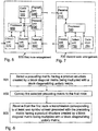
- is a flow chart illustrating embodiments of a method in a first node.
- Figure 5
- is a schematic block diagram illustrating embodiments of a first node arrangement.
- Figure 6
- is a flow chart illustrating embodiments of a method in a second node.
- Figure 7
- is a schematic block diagram illustrating embodiments of a second node arrangement.
- The invention is defined as a method and an arrangement in a respective first and second node, which may be put into practice in the embodiments described below.
-
Figure 1 depicts afirst node 100 in awireless communication system 110. Thewireless communication system 110 may be a cellular system and/or a system such as e.g. Long Term Evolution (LTE), Evolved - Universal Terrestrial Radio Access (E-UTRA), Worldwide Interoperability for Microwave Access (WiMAX), Universal Terrestrial Radio Access (UTRA), Wideband Code Division Multiple Access (WCDMA), GSM, Ultra Mobile Wideband (UMB) or any other wireless communication system using technologies that perform adaptation between different forms of transmission and use multiple antennas. Thefirst node 100 is arranged to communicate with asecond node 120 in thewireless communication system 110 over awireless channel 130. A linear and time-invariant MIMO filter may be used to model the input-output relation of the wireless channel during a sufficiently short transmission period. For sufficiently narrowband transmissions, a single matrix may be used for describing the filter. Such a channel matrix description also holds for modelling the channel over a subcarrier, (or several subcarriers as long they span a bandwidth which is small compared with the coherence bandwidth of the channel) in an Orthogonal Frequency Division Multiplexing (OFDM) system such as e.g. LTE. Thefirst node 100 may be any type of a base station such as e.g. a NodeB as in LTE. Thesecond node 120 may be a user equipment (UE) such as e.g. a mobile phone, a Personal Digital Assistant (PDA), a laptop. It may also be the other way around, that thefirst node 100 may be a UE such as e.g. a mobile phone, a Personal Digital Assistant (PDA) and thesecond node 120 may be any type of a base station such as e.g. a NodeB. In the example ofFigure 1 , thefirst node 100 is a base station and thesecond node 120 is a user equipment. In addition, thefirst node 100 and thesecond node 120 may constitute arbitrary wireless devices in communication with each other and with no particular hierarchical ordering. - The
first node 100 uses a multiple antenna system, i.e. uses multiple antennas for its transmission to thesecond node 120. Thesecond node 120 may also use a multiple antenna system for reception of the first node's transmission. This is thus a MIMO system, where the inputs to the channel corresponds to the transmit antennas in thefirst node 100 and the outputs to the receive antennas in thesecond node 120. Transmitter and receiver filtering/processing may also be considered to be included into the channel. Note that such a MIMO setup may include the special case of only one receive antenna.Figure 2 illustrates some embodiments wherein thefirst node 100 and asecond node 120 are each using a multiple antenna system comprising four antennas. Thefirst node 100 obtains aninformation carrying signal 140 being represented by a sequence of information bits, which information is to be conveyed to thesecond node 120 over thewireless channel 130.Figure 2 schematically illustrates thefirst node 100 as being the transmitting node (Tx) and thesecond node 120 as being the receiving node (Rx), thefirst node 100 and thesecond node 120 may use a multiple-antenna system 150, resulting in a MIMO link. In this example thefirst node 100 comprises four transmit antennas 160 1, 2, 3 and 4, e.g. a base station with four transmit antennas, and thesecond node 120 comprises four receiveantennas 170 1, 2, 3 and 4, e.g. a user equipment with four receive antennas. - In the example of
Figure 2 , thefirst node 100 comprises anencoding unit 162, apost precoding unit 163 and fourradio transmitter units 164. Theencoding unit 162 is arranged to receive theinformation carrying signal 140 to be transmitted. Theencoding unit 162 may further be arranged to possibly demultiplex the information bits into one or several information bit sequences, code these information bit sequences using some channel code (e.g. turbo code, low-density parity-check (LDPC) code, convolutional code), modulate the coded bits to produce symbols, map the symbols to a sequence of information carrying symbol vectors and precode the information carrying symbol vectors and finally forward the result to a possiblepost precoding unit 163. Thepost-precoding unit 163 may in the simplest of cases just forward the precoded signal (i.e., thepost precoding unit 163 is transparent and would hence be viewed as not existing) or it might process it in some way, e.g. perform digital filtering in baseband, before outputting possibly processed signals for transmission utilizing theradio transmitter units 164, using the respective transmit antennas 160 1, 2, 3 and 4 for transmitting the precoded signal to thesecond node 120. It is appreciated that the basic functions of the transmitter are well known for a skilled person and not described in detail. The transmitter in this example may support techniques such as Spatial-Division Multiple Access (SDMA), SDMA precoding, MIMO, MIMO precoding, and/or MIMO-SDMA. - In the example of
Figure 2 , thesecond node 120 comprises apre-processing unit 171, adecoding demodulation unit 172 and fourradio receiver units 174. Thesecond node 120 is arranged to receive the precoded signal from thefirst node 100. The signal is received by means of the receiveantennas 170 1, 2, 3 and 4, thepre-processing unit 171 and theradio receiver units 174. Thepre-processing unit 171 may implement various processing steps, e.g. it may perform filtering in base band or simply forward the signals unaltered to thedecoding demodulation unit 172. In the latter case, thepre-processing unit 171 may alternatively be considered not to be present (i.e., transparent corresponding to no pre-processing unit). Thedecoding demodulation unit 172 may be arranged to receive the coded signal from thepre-processing unit 171. Thedecoding demodulation unit 172 may further be arranged to demodulate the coded signal to data bits. It is appreciated that the basic functions of the receiver are well known for a skilled person and not described in detail herein. - It should also be noticed that both receiver in the
second node 120 and transmitter in thefirst node 100 may alter operation mode functioning as transmitter and receive, respectively. - As already indicated, the
encoding unit 162 in thefirst node 100 can be further subdivided into two parts, corresponding to a coding andmodulation unit 300 and aprecoding unit 310, such as e.g. a precoder. An example of a coding andmodulation unit 300 and aprecoding unit 310 is depicted inFigure 3 . The coding andmodulation unit 300 takes information bits as input and produces a sequence of information carrying symbol vectors, i.e. a vector-valued information-carrying signal as output. The information carrying symbol vectors can be seen as one or several symbol streams in parallel where each element of each vector s thus belongs to a certain symbol stream. The different symbol streams are commonly referred to as layers and at any given moment there are r different such layers corresponding to a transmission rank of r. Thus, the signal to be transmitted to thesecond node 120 over thewireless channel 130 comprises at least one symbol stream (or layer). The r symbols in a particular r × 1 information carrying symbol vector s is subsequently multiplied by an N T × r precoder matrix W NT ×r . where N T denotes the number of inputs (e.g. number of transmit antennas, number of antenna ports etc) of the MIMO channel. The mentioned precoding operation forwards the resulting output to thepost-processing unit 163. Thefirst node 100 determines a precoding matrix having a certain product structure, which will be further described in the sequel. This may be performed by choosing a precoding matrix to match the characteristics of the channel, i.e., to match an N R×N T MIMO channel matrix H. The precoder matrix W NT ×r may thus depend on the value of the channel H. The r information carrying symbols in s are typically complex-valued. Support of rank adaptation allows the number of simultaneously transmitted symbol streams, r, to be set to suit the current channel characteristics. Subsequent to precoding, the signals are conveyed over the channel H and received by an antenna array with N R elements. The receiver possibly processes the signals by means of thepre-processing unit 171. Collecting the signals into an N R × 1 vector y and considering the signals over a sufficiently narrow bandwidth, compared with the coherence bandwidth of the channel, gives the model
- Referring again to
Figure 2 thefirst node 100 comprises a multi-antenna system where in some embodiments at least one antenna emits radio waves in a horizontal polarization direction and at least one other antenna emits energy in the orthogonal (i.e., vertical) polarization direction. Such a dual-, or cross-, polarized antenna setup may thus contain a group of co-polarized antennas and another group of co-polarized antennas orthogonally polarized relative the former group. "Co-polarization" means the antennas are transmitting with the same polarization. Under ideal line-of-sight conditions, assuming ideal antenna responses and a similar dual-polarized antenna setup at the receive side, the cross-polarized antenna set-up results in a block diagonal channel matrix, which will be further explained below. In the example ofFigure 2 , the first two transmitantennas second node 120 are similarly arranged. The co-polarized antennas in the transmit array may be spaced sufficiently far apart so that the fading is roughly uncorrelated among the channels associated with the co-polarized elements. As mentioned above, the channel may be modelled using a channel matrix. Without loss of generality, by appropriately reordering the transmit and receive antenna elements, the 4x4 resulting channel matrix H, then tends to have the block-diagonal structure according to:
- With such a block-diagonal effective channel matrix, signals transmitted on antennas 160 1 and 2 in the
first node 100, do not reach receiveantennas 170 3 and 4, and, correspondingly, signals from transmit antennas 160 3 and 4 do not reach receiveantennas 170 1 and 2. As depicted inFigure 2 , for the first two transmitantennas antenna 170 1,
the complex-valued channel coefficient h 12 represents the effective channel involving the physical channel between transmit antenna 160 2 and receiveantenna 170 1, the complex-valued channel coefficient h 21 represents the effective channel involving the physical channel between transmit antenna 160 1 and receiveantenna 170 2, the complex-valued channel coefficient h 22 represents the effective channel involving the physical channel between transmit antenna 160 2 and receiveantenna 170 2. - Furthermore, as depicted in
Figure 2 , for the remaining two transmitantennas
the complex-valued channel coefficient h 33 represents the effective channel involving the physical channel between transmit antenna 160 3 and receiveantenna 170 3,
the complex-valued channel coefficient h 34 represents the effective channel involving the physical channel between transmit antenna 160 4 and receiveantenna 170 3,
the complex-valued channel coefficient h 43 represents the effective channel involving the physical channel between transmit antenna 160 3 and receiveantenna 170 4, and
the complex-valued channel coefficient h 44 represents the effective channel involving the physical channel between transmit antenna 160 4 and receiveantenna 170 4. - The general meaning of a block diagonal channel matrix is that it tends to have the structure

k × L̃l , k = 1, 2, ..., K ≠ l = 1, 2, ..., K and on-dlagonal M̃k ×L̃l blocks
1 × L̃2 are significantly lower than the average powers of the channel coefficients in the on-diagonal blocks
first node 100 and a similar cross-polarized antenna setup is used in thesecond node 120. The difference in average power between channel coefficients on the block diagonal and off the block diagonal is often, depending on the propagation scenario, around 6 dB or substantially higher. Even if the antenna setup used in thesecond node 120 is not exactly cross-polarized, the power differences may still be significant. - In the present solution, the
first node 100 determines a precoding matrix having a certain product structure. The notion of a product structure will be presented later and explicitly defined after the discussion on precoding and codebooks for precoding. The determined precoding matrix is to be used for precoding the at least one symbol stream (i.e., one or more layers) to be transmitted to thesecond node 120. The determination may be performed by choosing the precoding matrix to match the characteristics of the channel modelled using the channel matrix H. If the cross-polarized antenna setup at thefirst node 100 is using horizontal and vertically polarized antennas, a precoding with block diagonal structure is suitable since the use of a block diagonal structure precoder matches the block diagonal structure of the block diagonal channel matrix. However, if the mentioned antenna setup is instead using polarization oriented for example +-45 degrees, then the channel matrix is no longer likely to be as block diagonal as if horizontal and vertical polarizations would have been used. The precoder product structure is in this case beneficial since it involves decomposing the precoder into a product of two matrices, one unitary, so-called block diagonalizing unitary matrix, and one block diagonal matrix, where the latter matrix is multiplied from the left with the former. The block diagonalizing unitary matrix determined to be used, allows the +-45 degree cross-polarized antenna setup to be transformed into a virtual 0/90 degree cross-polarized antenna setup (i.e., horizontally and vertically polarized), which in turn sees a new resulting channel that has a tendency to be block diagonal. Since a block diagonal virtual channel is effectively obtained, the block diagonal precoder in the product structure can now be used to match its characteristics. Basically, the unitary matrix serves to rotate the polarizations so that the transmitted signals align with the vertical and horizontal directions. A benefit of such a product structure is that the precoders can be made to have constant modulus elements meaning that regardless of which exact product structure precoder is used, the same power is used on all the antenna ports. This thus solves the problem of having to deal with different transmit powers on the different power amplifiers (PAs). Thus, the product structure not only aligns the transmission in the beneficial horizontal and vertical polarizations but is also at the same time offering pooling of the PA powers between these two polarizations. - Referring to
Figure 2 , in some embodiments thefirst node 100 comprises acodebook 180. Thefirst node 100 may perform the determination of the precoding matrix having a certain product structure by selecting the precoding matrix having a product structure from thecodebook 180 comprised in thefirst node 100. - In some embodiments the
second node 120 comprises acode book 190 as shown inFigure 2 . Thesecond node 120 may select a precoding matrix from e.g. thecodebook 190 and recommend the first node to use the selected precoding matrix. This may be performed by conveying the recommended precoding matrix to thefirst node 100. Thefirst node 100 may then decide to use the recommended precoding matrix or exploit the provided channel information in some other way. - The
codebook codebook codebook codebook codebook codebook first node 100 orsecond node 120 is free to select a precoding matrix having said product structure from the codebook. Thecodebooks first node 100 and thesecond node 120. Also, the transmitter in thefirst node 100 may, for example, notify the receiver in thesecond node 120 of itscodebook 180. A suitable codebook structure will also have a product structure in the meaning that a significant number of the precoder elements use the product structure. As previously indicated, precoder elements with a product structure may be written as
The block diagonal characteristic of W pertains to the placement of zeros in the precoder matrices. A block diagonal precoder matrix W̃ = W̃ NT ×r may in general be written as


size 1 x1. Thus, the identity matrix can also be considered to have a block diagonal structure.
One example of a block diagonalizing unitary matrix is given by
Table 1: Example of a set of block diagonal W̃ matrices suitable especially well for two spatially separated (small distance) cross polarized antenna pairs in SU-MIMO mode. Tx Rank Codebook per Rank Table 1 1 

2 
Table 2: Example codebook of precoder matrices W having product structure. Tx Rank Codebook per Rank Table 1 

2 
- The codebook in Table 2, works fine as long as the two polarizations are well-separated, i.e., if the cross-polar discrimination (XPD) is sufficiently high. To improve the performance for scenarios with medium XPD, it is beneficial to allow the sign of the weights for the two polarizations to vary, as exemplified by the set of matrices for W̃ in Table 3, Table 4 and Table 5. This helps avoiding that the two polarizations cancel each other. The problem is then that even multiplying with the above V matrix leads to power imbalances among the PAs. In other words, not all elements in each precoder matrix/vector multiplication have the same magnitude. In this case, a better choice may be to multiply with

- This ensures that all elements have the same amplitude and thus enables full use of all PAs, yet it provides the advantage of transforming +-45 degree polarizations into vertical and horizontal polarizations, which provide better separation of the streams in multi-stream mode.
- The codebooks and the above unitary matrices can easily be generalized to other transmit array sizes (i.e., other than four antennas) and it is also possible to multiply the precoder elements from the right with some possibly unitary matrix or matrices and additional matrix multiplications from the left as well. This includes permuting the rows and/or columns of the precoder elements. These codebooks can also be subsets of larger codebooks. In conjunction to this, it should be noted that there are many equivalent ways of expressing the above product structure, in particular for the block diagonalizing unitary matrix V. For example, other equivalent forms of expressing the first exemplified V would be


- In general, the notion of a block diagonalizing unitary matrix is defined to mean a unitary (unitary up to a scaling factor) matrix such that for a particular cross-polarized antenna setup, it creates a virtual cross-polarized antenna setup which mimics the transmission from a cross-polarized antenna setup with vertically and horizontally polarized antennas, which at the same time ensures that together with the block diagonal matrices in the product structure, all scalar elements of the resulting product structure precoder matrices have the same absolute value. Thus, the block diagonalizing unitary matrix rotates the polarizations in said manner and ensures that the use of the PAs is balanced. Furthermore the notion of a 45 degree block diagonalizing unitary matrix is defined to mean a block diagonalizing unitary matrix that rotates the polarization directions 45 degrees.
Table 3: Example structure of set of W̃ matrices suitable especially well for two spatially separated (small distance) cross polarized antenna pairs in SU-MIMO mode. Note that for rotational simplicity, the scaling of the matrices so as to keep the total transmit power constant regardless of selected precoding matrix has intentionally been left out. Tx Rank Codebook per Rank Table 3 1 


2 

Table 4: Example structure of set of W̃ matrices suitable especially well for two spatially separated (large distance) cross polarized antenna pairs in SU-MIMO mode. Note that for notational simplicity, the scaling of the matrices so as to keep the total transmit power constant regardless of selected precoding matrix has intentionally been left out. Tx Rank Codebook per Rank Table 4 1 


2 


3 


4 

Table 5: Example structure of set of W̃ matrices suitable especially well for two spatially separated (large distance) cross polarized antenna pairs in SU-MIMO mode. Note that for natational simplicity, the scaling of the matrices so as to keep the total transmit power constant regardless of selected precoding matrix has intentionally been left out. Tx Rank Codebook per Rank Table 5 1 


2 
3 


4 

- Method steps in the
first node 100 for adapting a multi-antenna transmission to thesecond node 120 over awireless channel 130 according to some embodiments will now be described with reference to a flowchart depicted inFigure 4 . Thewireless channel 130 has at least three inputs and at least one output. Thefirst node 100 and thesecond node 120 are comprised in thewireless communication system 110. The method comprising the steps of: - 401. The first node obtains at least one symbol stream. The symbol stream is intended to be transmitted to the
second node 120 over the wireless channel. - 402. This step is optional. In some embodiments the
first node 100 receives channel information from thesecond node 120. Channel information is in general a quantity which is statistically related to the wireless channel. Examples of channel information includes channel estimates, quantized channel estimates, precoder recommendations etc. In particular, the received channel information may comprise a precoding matrix that thesecond node 120 recommends thefirst node 100 to use for the step of precoding. In some embodiments wherein said channel information comprises a channel estimate this channel estimate may be used by thefirst node 100 for determining a suitable precoder matrix for the transmission. - 403. In this step the
first node 100 determines a precoding matrix having a product structure created by a block diagonal matrix being multiplied from the left with a block diagonalizing unitary matrix.- In some embodiments the block diagonalizing unitary matrix is a 45 degree block diagonalizing unitary matrix.
- In some embodiments the
first node 100 has received channel information from thesecond node 120 in theoptional step 402. In these embodiments this step of determining the precoding matrix is performed based on the channel information received from thesecond node 120. - This step of determining the precoding matrix may also be performed by basing the determination on measurements carried out in a reverse link, i.e. measurements in the
first node 100 of received signals originating from transmissions from thesecond node 120, and/or exploiting channel reciprocity properties. Channel reciprocity means that the channel, or certain properties of the channel, is similar in the forward (fromfirst node 100 to second node 120) and reverse (fromsecond node 120 to first node 100) links. The measurements on a reverse link may comprise a channel estimate. - In some embodiments the
first node 100 comprises aprecoding codebook 180 comprising precoding elements, wherein at least half of the precoding elements in theprecoding codebook 180 have said product structure. In this case this step may be performed by selecting the precoding matrix having a product structure from thecode book 180. - The block diagonalizing unitary matrix may e.g. be equivalent to

- 404. The
first node 100 precedes the at least one symbol stream with the determined precoding matrix. - 405. The
first node 100 then transmits the precoded at least one symbol stream over awireless channel 130 to thesecond node 120. In some embodiments the transmission of the precoded at least one symbol stream in thefirst node 100 is conducted using a multi-antenna system with a cross-polarized antenna set-up. - To perform the method steps above, the
first node 100 comprises anarrangement 500 depicted inFigure 5 . As mentioned above, thefirst node 100 and thesecond node 120 are comprised in thewireless communication system 110. The first node arrangement is arranged to adapt a multi-antenna transmission to asecond node 120 over a wireless channel. Thewireless channel 130 has at least three inputs and at least one output. As mentioned above, thefirst node 100 and thesecond node 120 are comprised in thewireless communication system 110. - The
first node arrangement 500 comprises an obtainingunit 510 configured to obtain at least one symbol stream. - The
first node arrangement 500 further comprises a determiningunit 520 configured to determine a precoding matrix having a product structure created by a block diagonal matrix being multiplied from the left, with a block diagonalizing unitary matrix. In some embodiments the block diagonalizing unitary matrix is a 45 degree block diagonalizing unitary matrix. - The determining
unit 520 may further be configured to determine the precoding matrix by basing the determination on measurements on a reverse link and/or exploiting channel reciprocity properties. - The block diagonalizing unitary matrix may be equivalent to

- The
first node arrangement 500 further comprises aprecoding unit 530 configured to precode the at least one symbol stream with the determined precoding matrix. - The
first node arrangement 500 further comprises a transmittingunit 540 configured to transmit the precoded at least one symbol stream over awireless channel 130 to thesecond node 120. - In some embodiments the
first node arrangement 500 comprises aprecoding codebook 180. Theprecoding codebook 180 may comprise precoding elements, wherein at least half of the precoding elements in theprecoding codebook 180 have said product structure. In this case the determiningunit 520 may be configured to select the precoding matrix having a product structure from theprecoding codebook 180. - In some embodiments the
first node arrangement 500 comprises a receivingunit 550 configured to receive channel information from thesecond node 120. In this case the determiningunit 520 may be configured to determine the precoding matrix based on the channel information received from thesecond node 120. - The channel information may comprise a precoding matrix that the
second node 120 recommends thefirst node 100 to use for the precoding. - In some embodiments the channel information comprises a channel estimate.
- The
first node arrangement 500 may further comprise a multi-antenna system with a cross-polarized antenna set-up. In this case the transmittingunit 540 may be configured to transmit the precoded at least one symbol stream in thefirst node 100 using said multi-antenna. - Method steps in the
second node 100 for receiving a multi-antenna transmission from afirst node 100 over awireless channel 130 according to some embodiments will now be described with reference to a flowchart depicted inFigure 6 . Thewireless channel 130 has at least three inputs and at least one output. As mentioned above, thefirst node 100 and thesecond node 120 are comprised in awireless communication system 110. The method comprising the step of: - 601. This is an optional step. The second node selects a precoding matrix to be recommended to be used by the
first node 100 for precoding a transmission.- A
precoding codebook 180, 190may be comprised in thesecond node 120. In that case the recommended precoding matrix may be selected out of saidprecoding codebook
- A
- 602. This is an optional step. The
second node 120 conveys channel information to thefirst node 100. The channel information may be used by thefirst node 100 as base for determining a precoding matrix with which a transmission corresponding to at least one symbol stream shall be precoded.- If the
optional step 601 is performed said conveyed channel information may be represented by the recommended precoding matrix.
- If the
- 603. The
second node 100 receives a transmission corresponding to at least one symbol stream over awireless channel 130 conveyed from thefirst node 100. The at least one symbol stream is precoded with a precoding matrix having a product structure created by a block diagonal matrix being multiplied from the left, with a block diagonalizing unitary matrix. In some embodiments the block diagonalizing unitary matrix is a 45 degree block diagonalizing unitary matrix.- The precoding matrix may be comprised in a
precoding codebook - The block diagonalizing unitary matrix may be equivalent to

- In some embodiments the reception of said transmission of the precoded at least one symbol stream is performed by using a multi-antenna system with a cross-polarized antenna setup.
- The precoding matrix may be comprised in a
- To perform the method steps above, the
second node 120 comprises anarrangement 700 depicted inFigure 7 . As mentioned above, thesecond node 120 is arranged to receive a multi-antenna transmission from afirst node 100 over awireless channel 130. The wireless channel has at least three inputs and at least one output. Thefirst node 100 and thesecond node 120 are comprised in awireless communication system 110. - The
second node arrangement 700 comprises a receivingunit 710 configured to receive a transmission corresponding to at least one symbol stream over awireless channel 130 conveyed from thefirst node 100. The at least one symbol stream is precoded with a precoding matrix having a product structure created by a block diagonal matrix being multiplied from the left with a block diagonalizing unitary matrix. In some embodiments the block diagonalizing unitary matrix is a 45 degree block diagonalizing unitary matrix. The precoding matrix may be comprised in aprecoding codebook precoding codebook first node 100 or thesecond node 120. - The block diagonalizing unitary matrix may e.g. be equivalent to

- In some embodiments the
second node arrangement 700 further comprises a conveyingunit 720 configured to convey channel information to thefirst node 100. The channel information may be used by thefirst node 100 as base for determining the precoding matrix with which the received at least one symbol stream will be precoded. - In some embodiments the channel information arranged to be conveyed comprises a channel estimate.
- The
second node arrangement 700 may further comprise a selectingunit 730 configured to select the precoding matrix to be recommended to be used by thefirst node 100 for precoding said transmission. - The channel information arranged to be conveyed by the conveying
unit 720 to thefirst node 100, may be represented by the selected and recommended precoding matrix. - In some embodiments the
precoding codebook 190 is comprised in thesecond node 120. In this case the recommended precoding matrix may be selected out of saidprecoding codebook - In some embodiments the
second node arrangement 700 further comprises a multi-antenna system with a cross-polarized antenna setup. In this case the receivingunit 710 further may be configured to receive said transmission of the precoded at least one symbol stream by using said multi-antenna system. - Some embodiments of the present method may be described as a method for enhancing performance in a wireless communication environment, comprising: modifying a pre-coding scheme by multiplying one or several of: codebook pre-coder elements, a transmitted signal, or parts thereof, before or after possible pilots, with certain unitary matrices and extending a block diagonal codebook with non-block diagonal elements.
- Non-block diagonal elements may be added to the block diagonal codebook to improve performance where cross polar discrimination is not infinite.
- All the elements in said codebook may be multiplied with a unitary matrix to transform a ±45 degree cross-polarized antenna array into a virtual vertically and horizontally polarized array.
- In some embodiments the same unitary matrix is chosen so as to balance power among the power amplifiers.
- Some embodiments of the present method may be described as a wireless communication device comprising a processor configured to select a transmission mode of a plurality of transmission modes from a codebook, and a memory coupled with the processor. The processor is further configured to modify a pre-coding scheme in said memory by multiplying one or several of: codebook pre-coder elements, a transmitted signal, or parts thereof, before or after possible pilots, with certain unitary matrices and extending a block diagonal codebook with non-block diagonal elements.
- Some embodiments of the present method may be described as a computer-readable media including instructions stored thereon comprising: instructions for processing and modifying a pre-coding scheme by multiplying one or several of: codebook pre-coder elements, a transmitted signal, or parts thereof, before or after possible pilots, with certain unitary matrices and extending a block diagonal codebook with non-block diagonal elements.
- The present mechanism for adapting a multi-antenna transmission transmitted from a fist node over a wireless channel and being received by a
second node 120 may be implemented through one or more processors, such as theprocessor 560 in thefirst node arrangement 500 depicted inFigure 5 or theprocessor 740 in thesecond node arrangement 700 depicted inFigure 7 , together with computer program code for performing the functions of the present solution. The program code mentioned above may also be provided as a computer program product, for instance in the form of a data carrier carrying computer program code for performing the present solution when being loaded into thefirst node 100 or thesecond node 120. One such carrier may be in the form of a CD ROM disc. It is however feasible with other data carriers such as a memory stick. The computer program code can furthermore be provided as pure program code on a server and downloaded tofirst node 100 orsecond node 120 remotely. - When using the word "comprise" or "comprising" it shall be interpreted as nonlimiting, i.e. meaning "consist at least of".
- The present invention is not limited to the above described embodiments. Various alternatives, modifications and equivalents may be used.
- 1. An exemplary method in a first node (100) for adapting a multi-antenna transmission to a second node (120) over a wireless channel (130), the wireless channel (130) having at least three inputs and at least one output, the first node (100) and the second node (120) being comprised in a wireless communication system (110), the method comprising the steps of:
- obtaining (401) at least one symbol stream,
- determining (403) a precoding matrix having a product structure created by a block diagonal matrix being multiplied from the left with a block diagonalizing unitary matrix,
- precoding (404) the at least one symbol stream with the determined precoding matrix, and
- transmitting (405) the precoded at least one symbol stream over a wireless channel (130) to the second node (120).
- 2. The exemplary method according to
exemplary method 1, wherein said block diagonalizing unitary matrix is a 45 degree block diagonalizing unitary matrix. - 3. The exemplary method according to any of the exemplary methods 1-2, wherein the step of determining (403) a precoding matrix is performed by selecting the precoding matrix having a product structure from a precoding codebook (180, 190) comprising precoding elements, wherein at least half of the precoding elements in the precoding codebook (180, 190) have said product structure.
- 4. The exemplary method according to any of the exemplary methods 1-3, wherein the block diagonalizing unitary matrix is equivalent to

- 5. The exemplary method according to any of the exemplary methods 1-3, wherein the block diagonalizing unitary matrix is equivalent to

- 6. The exemplary method according to any of the exemplary methods 1-5, comprising the further step of:
- receiving (402) channel information from the second node (120), and wherein the step of determining (403) the precoding matrix is performed based on the channel information received from the second node (120).
- 7. The exemplary method according to exemplary method 6, wherein said received channel information comprises a precoding matrix that the second node (120) recommends the first node (100) to use for the step of precoding (404).
- 8. The exemplary method according to exemplary method 6, wherein said received channel information comprises a channel estimate.
- 9. The exemplary method according to any of the exemplary methods 1-8, wherein the step of determining (403) the precoding matrix is performed by basing the determination on measurements on a reverse link and/or exploiting channel reciprocity properties.
- 10. The exemplary method according to any of the exemplary methods 1-9, wherein the transmission of the precoded at least one symbol stream in the first node (100) is conducted using a multi-antenna system with a cross-polarized antenna set-up.
- 11. An exemplary method in a second node (120) for receiving a multi-antenna transmission from a first node (100) over a wireless channel (130), the wireless channel (130) having at least three inputs and at least one output, the first node (100) and the second node (120) being comprised in a wireless communication system (110), the method comprising the step of:
- receiving (603) a transmission corresponding to at least one symbol stream over a wireless channel (130) conveyed from the first node (100), which at least one symbol stream is precoded with a precoding matrix having a product structure created by a block diagonal matrix being multiplied from the left with a block diagonalizing unitary matrix.
- 12. The exemplary method according to exemplary method 11, wherein said block diagonalizing unitary matrix is a 45 degree block diagonalizing unitary matrix.
- 13. The exemplary method according to any of the exemplary methods 11-12, wherein said precoding matrix is comprised in a precoding codebook of finite size wherein at least half of the precoding elements in the precoding codebook have said product structure.
- 14. The exemplary method according to any of the exemplary methods 11-13, wherein the block diagonalizing unitary matrix is equivalent to

- 15. The exemplary method according to any of the exemplary methods 11-13, wherein the block diagonalizing unitary matrix is equivalent to

- 16. The exemplary method according to any of the exemplary methods 11-15, further comprising the step of
- conveying (602) channel information to the first node (100), which channel information is used by the first node (100) as base for determining the precoding matrix with which the received at least one symbol stream is precoded.
- 17. The exemplary method according to exemplary method 16, comprising the further step of:
- selecting (601) the precoding matrix to be recommended to be used by the first node (100) for precoding said transmission,
- wherein said conveyed channel information in the step of conveying (602) the channel information to the first node (100), is represented by the recommended precoding matrix.
- 18. The exemplary method according to exemplary method 17, wherein the precoding codebook is comprised in the second node (120), and wherein the recommended precoding matrix is selected out of said precoding codebook.
- 19. The exemplary method according to exemplary method 16, wherein said conveyed channel information comprises a channel estimate.
- 20. The exemplary method according to any of the exemplary methods 11-19, wherein the reception of said transmission of the precoded at least one symbol stream is performed by using a multi-antenna system with a cross-polarized antenna setup.
- 21. An exemplary arrangement (500) in a first node (100), for adapting a multi-antenna transmission to a second node (120) over a wireless channel (130), the wireless channel (130) having at least three inputs and at least one output, the first node (100) and the second node (120) being comprised in a wireless communication system (110), the first node arrangement comprising:
- an obtaining unit (510) configured to obtain at least one symbol stream,
- a determining unit (520) configured to determine a precoding matrix having a product structure created by a block diagonal matrix being multiplied from the left with a block diagonalizing unitary matrix,
- a precoding unit (530) configured to precode the at least one symbol stream with the determined precoding matrix, and
- a transmitting unit (540) configured to transmit the precoded at least one symbol stream over a wireless channel to the second node (120).
- 22. An exemplary arrangement (700) in a second node (120), for receiving a multi-antenna transmission from a first node (100) over a wireless channel (130), the wireless channel (130) having at least three inputs and at least one output, the first node (100) and the second node (120) being comprised in a wireless communication system (110), the second node arrangement (700) comprising:
- a receiving unit (710) configured to receive a transmission corresponding to at least one symbol stream over a wireless channel conveyed from the first node (100), which at least one symbol stream is precoded with a precoding matrix having a product structure created by a block diagonal matrix being multiplied from the left with a block diagonalizing unitary matrix.
Claims (17)
- A method in a base station (100) for adapting a multi-antenna transmission to a user equipment (120) over a wireless channel (130), the method comprising the steps of:obtaining (401) at least one symbol stream,determining (403) a precoding matrix having a product structure wherein the product structure is decomposable into a block diagonal matrix being multiplied from the left with a block diagonalizing unitary matrix,precoding (404) the at least one symbol stream with the determined precoding matrix, andtransmitting (405) the precoded at least one symbol stream over a wireless channel (130) to the user equipment (120).
- The method according to claim 1 wherein the precoding matrix comprises elements and where each element in the precoding matrix has the same magnitude.
- The method according to claim 1, wherein said block diagonalizing unitary matrix is a 45 degree block diagonalizing unitary matrix.
- The method according to any of claims 1-3, wherein the step of determining (403) a precoding matrix is performed by selecting the precoding matrix having a product structure, wherein the product structure is decomposable into a block diagonal matrix being multiplied from the left with a block diagonalizing unitary matrix, from a precoding codebook (180,190) comprising precoding elements, wherein at least half of the precoding elements in the precoding codebook (180,190) have said product structure.
- A method in a user equipment (120) for receiving a multi-antenna transmission from a base station (100) over a wireless channel (130), the method comprising the step of:receiving (603) a transmission corresponding to at least one symbol stream over a wireless channel (130) conveyed from the base station (100), which at least one symbol stream is precoded with a precoding matrix having a product structure that is decomposable into a block diagonal matrix being multiplied from the left with a block diagonalizing unitary matrix; anddemodulate the at least one symbol stream.
- The method according to claim 5 wherein the precoding matrix comprises elements and where each element in the precoding matrix has the same magnitude.
- The method according to claim 5, wherein said block diagonalizing unitary matrix is a 45 degree block diagonalizing unitary matrix.
- The method according to any of claims 5-7, wherein said precoding matrix is comprised in a precoding codebook of finite size wherein at least half of the precoding elements in the precoding codebook have said product structure.
- The method according to any of claims 5-8, wherein the block diagonalizing unitary matrix is equivalent to

- A base station (100), for adapting a multi-antenna transmission to a user equipment (120) over a wireless channel (130), the base station arrangement comprising:an obtaining unit (510) configured to obtain at least one symbol stream,a determining unit (520) configured to determine a precoding matrix having a product structure, wherein the product structure is decomposable into a block diagonal matrix being multiplied from the left with a block diagonalizing unitary matrix,a precoding unit (530) configured to precode the at least one symbol stream with the determined precoding matrix, anda transmitting unit (540) configured to transmit the precoded at least one symbol stream over a wireless channel to the user equipment (120).
- The base station (100)according to claim 10 wherein the precoding matrix comprises elements and where each element in the precoding matrix has the same magnitude.
- A user equipment (120), for receiving a multi-antenna transmission from a base station (100) over a wireless channel (130), the user equipment arrangement (700) comprising:a receiving unit (710) configured to receive a transmission corresponding to at least one symbol stream over a wireless channel conveyed from the base station (100), which at least one symbol stream is precoded with a precoding matrix having a product structure, wherein the product structure is decomposable into a block diagonal matrix being multiplied from the left with a block diagonalizing unitary matrix; anda decoding demodulation unit (172) configured to demodulate the at least on symbol stream.
- The user equipment (120) according to claim 12 wherein the precoding matrix comprises elements and where each element in the precoding matrix has the same magnitude.
- The user equipment (120) according to any of claims 12-13, wherein said block diagonalizing unitary matrix is a 45 degree block diagonalizing unitary matrix.
- The user equipment (120) according to any of claims 12-14, wherein said precoding matrix is comprised in a precoding codebook of finite size wherein at least half of the precoding elements in the precoding codebook have said product structure.
- The user equipment (120) according to any of claims 12-15, wherein the block diagonalizing unitary matrix is equivalent to

- The user equipment (120) according to any of claims 12-16, wherein the block diagonalizing unitary matrix is equivalent to

Applications Claiming Priority (4)
| Application Number | Priority Date | Filing Date | Title |
|---|---|---|---|
| SE0701054 | 2007-04-30 | ||
| PCT/SE2008/050374 WO2008133582A2 (en) | 2007-04-30 | 2008-03-31 | Method and arrangement for adapting a multi-antenna transmission |
| EP08724320A EP2145400B1 (en) | 2007-04-30 | 2008-03-31 | Method and arrangement for adapting a multi-antenna transmission |
| EP13153994.2A EP2615785B1 (en) | 2007-04-30 | 2008-03-31 | Method and arrangement for adapting a multi-antenna transmission |
Related Parent Applications (2)
| Application Number | Title | Priority Date | Filing Date |
|---|---|---|---|
| EP08724320A Division EP2145400B1 (en) | 2007-04-30 | 2008-03-31 | Method and arrangement for adapting a multi-antenna transmission |
| EP13153994.2A Division EP2615785B1 (en) | 2007-04-30 | 2008-03-31 | Method and arrangement for adapting a multi-antenna transmission |
Publications (2)
| Publication Number | Publication Date |
|---|---|
| EP3249869A1 true EP3249869A1 (en) | 2017-11-29 |
| EP3249869B1 EP3249869B1 (en) | 2019-05-15 |
Family
ID=39926218
Family Applications (3)
| Application Number | Title | Priority Date | Filing Date |
|---|---|---|---|
| EP08724320A Active EP2145400B1 (en) | 2007-04-30 | 2008-03-31 | Method and arrangement for adapting a multi-antenna transmission |
| EP13153994.2A Active EP2615785B1 (en) | 2007-04-30 | 2008-03-31 | Method and arrangement for adapting a multi-antenna transmission |
| EP17179776.4A Active EP3249869B1 (en) | 2007-04-30 | 2008-03-31 | Method and arrangement for adapting a multi-antenna transmission |
Family Applications Before (2)
| Application Number | Title | Priority Date | Filing Date |
|---|---|---|---|
| EP08724320A Active EP2145400B1 (en) | 2007-04-30 | 2008-03-31 | Method and arrangement for adapting a multi-antenna transmission |
| EP13153994.2A Active EP2615785B1 (en) | 2007-04-30 | 2008-03-31 | Method and arrangement for adapting a multi-antenna transmission |
Country Status (11)
| Country | Link |
|---|---|
| US (6) | US8306140B2 (en) |
| EP (3) | EP2145400B1 (en) |
| JP (2) | JP5039831B2 (en) |
| KR (1) | KR101478379B1 (en) |
| CN (1) | CN101675602B (en) |
| DK (2) | DK2145400T3 (en) |
| ES (2) | ES2407118T3 (en) |
| PL (2) | PL2145400T3 (en) |
| PT (1) | PT2145400E (en) |
| TW (1) | TWI445363B (en) |
| WO (1) | WO2008133582A2 (en) |
Families Citing this family (72)
| Publication number | Priority date | Publication date | Assignee | Title |
|---|---|---|---|---|
| WO2008133582A2 (en) * | 2007-04-30 | 2008-11-06 | Telefonaktiebolaget L M Ericsson (Publ) | Method and arrangement for adapting a multi-antenna transmission |
| KR101056614B1 (en) * | 2008-07-30 | 2011-08-11 | 엘지전자 주식회사 | Data transmission method in multi-antenna system |
| JP5322327B2 (en) * | 2009-01-05 | 2013-10-23 | マーベル ワールド トレード リミテッド | Precoding of codebook for MIMO communication system |
| US8385441B2 (en) | 2009-01-06 | 2013-02-26 | Marvell World Trade Ltd. | Efficient MIMO transmission schemes |
| PL2375604T3 (en) * | 2009-01-07 | 2019-01-31 | Sun Patent Trust | Wireless communication apparatus, wireless communication system and wireless communication method |
| US8503572B2 (en) * | 2009-02-02 | 2013-08-06 | Qualcomm Incorporated | Antenna virtualization in a wireless communication environment |
| US8238483B2 (en) | 2009-02-27 | 2012-08-07 | Marvell World Trade Ltd. | Signaling of dedicated reference signal (DRS) precoding granularity |
| US8699528B2 (en) | 2009-02-27 | 2014-04-15 | Marvell World Trade Ltd. | Systems and methods for communication using dedicated reference signal (DRS) |
| CN102428658B (en) * | 2009-03-17 | 2015-02-18 | 诺基亚通信公司 | Method and apparatus for codebook-based precoding in MIMO systems |
| CN104539332B (en) * | 2009-03-17 | 2018-08-17 | 诺基亚通信公司 | Method and apparatus for the precoding based on code book in mimo system |
| WO2010122432A1 (en) | 2009-04-21 | 2010-10-28 | Marvell World Trade Ltd | Multi-point opportunistic beamforming with selective beam attenuation |
| WO2010124445A1 (en) * | 2009-04-27 | 2010-11-04 | 华为技术有限公司 | A codebook, codebook generation method, uplink transmitting method and equipment based on codebook |
| CN101877609B (en) * | 2009-04-30 | 2013-06-12 | 富士通株式会社 | Communication device, base station and multipoint cooperative communication method |
| GB0909466D0 (en) * | 2009-06-02 | 2009-07-15 | Nokia Siemens Networks Oy | Method and apparatus for antenna virtualization for multimode diversity transmission |
| WO2010142323A1 (en) * | 2009-06-08 | 2010-12-16 | Telefonaktiebolaget L M Ericsson (Publ) | Wireless communication node connections |
| TWI415329B (en) * | 2009-06-15 | 2013-11-11 | Senao Networks Inc | Multi-incoming and outgoing RF transmitter and receiver |
| JP5122529B2 (en) * | 2009-06-23 | 2013-01-16 | 株式会社エヌ・ティ・ティ・ドコモ | Mobile terminal apparatus, radio base station apparatus, radio communication method, and radio communication system |
| US8761281B2 (en) * | 2009-06-29 | 2014-06-24 | Telefonaktiebolaget L M Ericsson (Publ) | Method and arrangement for adapting a signal in a wireless communications network |
| US9628250B2 (en) * | 2009-08-05 | 2017-04-18 | Spatial Digital Systems, Inc. | Advanced beam-forming technology with cross-polarization cancellation schemes |
| WO2011020226A1 (en) * | 2009-08-18 | 2011-02-24 | 上海贝尔股份有限公司 | Method and device for constructing codebook, method, device and system for precoding |
| JP5149257B2 (en) * | 2009-10-02 | 2013-02-20 | シャープ株式会社 | Wireless communication system, communication apparatus, and wireless communication method |
| US8675794B1 (en) | 2009-10-13 | 2014-03-18 | Marvell International Ltd. | Efficient estimation of feedback for modulation and coding scheme (MCS) selection |
| US8917796B1 (en) | 2009-10-19 | 2014-12-23 | Marvell International Ltd. | Transmission-mode-aware rate matching in MIMO signal generation |
| CN102550079B (en) | 2009-11-09 | 2015-10-21 | 马维尔国际贸易有限公司 | For the asymmetric feedback of coordinated emission system |
| WO2011059248A2 (en) | 2009-11-12 | 2011-05-19 | 엘지전자 주식회사 | Mu-mimo transmission method in wireless lan system |
| CN102783120B (en) | 2009-12-17 | 2015-07-01 | 马维尔国际贸易有限公司 | MIMO feedback schemes for cross-polarized antennas |
| CN102130751B (en) * | 2010-01-20 | 2013-06-12 | 电信科学技术研究院 | Method, system and device for transmitting/receiving information by multi-antenna system |
| JP5258002B2 (en) | 2010-02-10 | 2013-08-07 | マーベル ワールド トレード リミテッド | Device, mobile communication terminal, chipset, and method in MIMO communication system |
| US8687741B1 (en) | 2010-03-29 | 2014-04-01 | Marvell International Ltd. | Scoring hypotheses in LTE cell search |
| CN101826945B (en) * | 2010-04-05 | 2015-08-12 | 中兴通讯股份有限公司 | The sending method of channel information and device |
| CN101834698B (en) * | 2010-04-05 | 2016-01-13 | 中兴通讯股份有限公司 | The sending method of channel information and device |
| CN101834629B (en) * | 2010-04-06 | 2014-10-22 | 中兴通讯股份有限公司 | Method and system for indicating transmission parameters |
| EP2556599B1 (en) | 2010-04-07 | 2016-11-09 | Telefonaktiebolaget LM Ericsson (publ) | Parameterized codebook with subset restrictions for use with precoding mimo transmissions |
| WO2011162422A1 (en) * | 2010-06-21 | 2011-12-29 | Pantech Co., Ltd. | Transmitter and receiver, method thereof in wireless communication system |
| KR101754669B1 (en) | 2010-07-29 | 2017-07-06 | 엘지전자 주식회사 | Method and device for sending and receiving precoded signals on a wireless communication system |
| JP5643569B2 (en) * | 2010-08-04 | 2014-12-17 | シャープ株式会社 | Control station equipment |
| CN102377467B (en) * | 2010-08-23 | 2015-02-04 | 中国移动通信集团公司 | Eight-antenna downlink control channel sending method and device |
| JP2012100254A (en) | 2010-10-06 | 2012-05-24 | Marvell World Trade Ltd | Codebook subsampling for pucch feedback |
| US8615052B2 (en) | 2010-10-06 | 2013-12-24 | Marvell World Trade Ltd. | Enhanced channel feedback for multi-user MIMO |
| US9048970B1 (en) | 2011-01-14 | 2015-06-02 | Marvell International Ltd. | Feedback for cooperative multipoint transmission systems |
| US8861391B1 (en) | 2011-03-02 | 2014-10-14 | Marvell International Ltd. | Channel feedback for TDM scheduling in heterogeneous networks having multiple cell classes |
| US9124327B2 (en) | 2011-03-31 | 2015-09-01 | Marvell World Trade Ltd. | Channel feedback for cooperative multipoint transmission |
| US20120328031A1 (en) * | 2011-06-24 | 2012-12-27 | Nokia Siemens Networks Oy | Codebooks for Mobile Communications |
| CN102868479B (en) | 2011-07-07 | 2015-06-03 | 华为技术有限公司 | Method, device and system for multi-antenna transmission |
| US8976713B2 (en) * | 2011-08-02 | 2015-03-10 | Electronics And Telecommunications Research Institute | Method and apparatus for performing transmission and reception simultaneously in same frequency band |
| US8654816B2 (en) * | 2011-10-18 | 2014-02-18 | Telefonaktiebolaget L M Ericsson (Publ) | Methods and devices for determining a transmission rank |
| US8923427B2 (en) | 2011-11-07 | 2014-12-30 | Marvell World Trade Ltd. | Codebook sub-sampling for frequency-selective precoding feedback |
| US9020058B2 (en) | 2011-11-07 | 2015-04-28 | Marvell World Trade Ltd. | Precoding feedback for cross-polarized antennas based on signal-component magnitude difference |
| WO2013068974A1 (en) | 2011-11-10 | 2013-05-16 | Marvell World Trade Ltd. | Differential cqi encoding for cooperative multipoint feedback |
| US9220087B1 (en) | 2011-12-08 | 2015-12-22 | Marvell International Ltd. | Dynamic point selection with combined PUCCH/PUSCH feedback |
| US8902842B1 (en) | 2012-01-11 | 2014-12-02 | Marvell International Ltd | Control signaling and resource mapping for coordinated transmission |
| WO2013129985A1 (en) * | 2012-03-02 | 2013-09-06 | Telefonaktiebolaget L M Ericsson (Publ) | Radio base station and method therein for transforming a data transmission signal |
| CN103297102B (en) * | 2012-03-02 | 2017-11-21 | 北京新岸线移动多媒体技术有限公司 | The pre-coding matrix of wave beam forming provides and preparation method, apparatus and system |
| US9143951B2 (en) | 2012-04-27 | 2015-09-22 | Marvell World Trade Ltd. | Method and system for coordinated multipoint (CoMP) communication between base-stations and mobile communication terminals |
| EP2860897B1 (en) | 2012-07-02 | 2017-11-01 | Huawei Technologies Co., Ltd. | Method for determining precoding matrix indicator, user equipment and base station |
| CN103580785A (en) * | 2012-07-27 | 2014-02-12 | 华为技术有限公司 | Upstream control information feedback method under downstream MIMO mode and user equipment |
| US9100052B2 (en) * | 2013-02-01 | 2015-08-04 | Samsung Electronics Co., Ltd. | QC-LDPC convolutional codes enabling low power trellis-based decoders |
| EP2984765B1 (en) * | 2013-04-10 | 2018-12-26 | LG Electronics Inc. | Layer alignment method and apparatus for multilayer three-dimensional beamforming in wireless communication system |
| CN107872261B (en) | 2013-04-15 | 2023-04-11 | 华为技术有限公司 | Method for reporting channel state information, user equipment and base station |
| CN103475609B (en) * | 2013-09-02 | 2016-11-09 | 华为技术有限公司 | Communication equipment, Base Band Unit and communication means |
| CN106576280B (en) * | 2014-01-31 | 2020-09-22 | 劲通开曼有限公司 | Antenna system with beamwidth control |
| EP3133747B1 (en) | 2014-05-15 | 2018-12-12 | Huawei Technologies Co. Ltd. | Method and apparatus for transmitting and feeding back signal |
| US9722841B1 (en) * | 2014-07-16 | 2017-08-01 | University Of South Florida | Channel-based coding for wireless communications |
| BR112017005953B8 (en) | 2014-09-25 | 2023-10-10 | Ericsson Telefon Ab L M | Method performed by a base station to enable a user equipment to determine a precoder codebook and related base station, method performed by a user equipment to determine a precoder codebook and related user equipment |
| CN113872654A (en) * | 2016-01-29 | 2021-12-31 | 瑞典爱立信有限公司 | Beamforming using antenna arrays |
| US11201647B2 (en) * | 2016-08-11 | 2021-12-14 | Motorola Mobility Llc | Method and apparatus for equal energy codebooks for coupled antennas with transmission lines |
| US11075740B2 (en) | 2018-05-07 | 2021-07-27 | ENK Wireless, Inc. | Systems/methods of communications using a plurality of cooperative devices |
| US10681716B2 (en) | 2018-05-07 | 2020-06-09 | ENK Wireless, Inc. | Systems/methods of providing increased wireless capacity, vehicular safety, electrical power wirelessly, and device control responsive to geographic position |
| US10804998B2 (en) * | 2018-05-07 | 2020-10-13 | ENK Wireless, Inc. | Systems/methods of providing increased wireless capacity, vehicular safety, electrical power wirelessly, and device control responsive to geographic position |
| US11100796B2 (en) | 2018-05-07 | 2021-08-24 | ENK Wireless, Inc. | Systems/methods of improving vehicular safety |
| KR102586755B1 (en) * | 2018-06-11 | 2023-10-10 | 삼성전자 주식회사 | Method and apparatus for determining a codebook in non-orthogonal multiple access system |
| US10965352B1 (en) * | 2019-09-24 | 2021-03-30 | Rampart Communications, Inc. | Communication system and methods using very large multiple-in multiple-out (MIMO) antenna systems with extremely large class of fast unitary transformations |
Citations (3)
| Publication number | Priority date | Publication date | Assignee | Title |
|---|---|---|---|---|
| US20040042439A1 (en) * | 2002-08-27 | 2004-03-04 | Menon Murali Paravath | Beam-steering and beam-forming for wideband MIMO/MISO systems |
| WO2004038952A2 (en) * | 2002-10-25 | 2004-05-06 | Qualcomm, Incorporated | Channel estimation and spatial processing for tdd mimo systems |
| WO2006007148A1 (en) * | 2004-06-23 | 2006-01-19 | Intel Corporation | Closed loop mimo systems using codebooks for feedback |
Family Cites Families (24)
| Publication number | Priority date | Publication date | Assignee | Title |
|---|---|---|---|---|
| JP3939165B2 (en) * | 2002-02-20 | 2007-07-04 | 三洋電機株式会社 | Wireless device, wireless communication system, space path control method, and space path control program |
| US8208364B2 (en) * | 2002-10-25 | 2012-06-26 | Qualcomm Incorporated | MIMO system with multiple spatial multiplexing modes |
| FR2848747A1 (en) * | 2002-12-16 | 2004-06-18 | France Telecom | Pre-coded signal emitting process for wireless communication system, involves interlacing pre-coded transmitted symbols to modify temporal order of symbols and coding each block of symbols according to coding time space |
| FR2853480B1 (en) * | 2003-04-01 | 2005-06-17 | METHOD AND DEVICE FOR AUTOMATICALLY IDENTIFYING A SUBDEFINED MIXTURE OF SOURCES IN THE FOURTH ORDER | |
| KR100575993B1 (en) * | 2003-08-07 | 2006-05-02 | 삼성전자주식회사 | Method and apparatus for scheduling multi-user in wireless communication system using multiple transmit/receive antenna |
| GB2415863A (en) * | 2004-07-01 | 2006-01-04 | British Sky Broadcasting Ltd | Wireless network system and devices with redundancy between orthogonally polarised beams |
| KR20060038812A (en) * | 2004-11-01 | 2006-05-04 | 엘지전자 주식회사 | Method for transmitting precoding matrix and transmitting signal using the precoding matrix |
| WO2006052890A1 (en) * | 2004-11-05 | 2006-05-18 | University Of Florida Research Foundation, Inc. | Uniform channel decomposition for mimo communications |
| US7974359B2 (en) * | 2004-12-22 | 2011-07-05 | Qualcomm Incorporated | Methods and apparatus for mitigating multi-antenna correlation effect in communication systems |
| US7933353B2 (en) * | 2005-09-30 | 2011-04-26 | Intel Corporation | Communication system and technique using QR decomposition with a triangular systolic array |
| US20070099578A1 (en) * | 2005-10-28 | 2007-05-03 | Kathryn Adeney | Pre-coded diversity forward channel transmission system for wireless communications systems supporting multiple MIMO transmission modes |
| US7917176B2 (en) * | 2006-02-14 | 2011-03-29 | Nec Laboratories America, Inc. | Structured codebook and successive beamforming for multiple-antenna systems |
| KR100918747B1 (en) * | 2006-02-07 | 2009-09-24 | 삼성전자주식회사 | Apparatus and method for transmitting uplink signal in mobile communication system using an orthogonal frequency division multiple access scheme |
| KR101066151B1 (en) * | 2006-08-17 | 2011-09-20 | 인터디지탈 테크날러지 코포레이션 | Method and apparatus for providing efficient precoding feedback in a mimo wireless communication system |
| KR20080022033A (en) * | 2006-09-05 | 2008-03-10 | 엘지전자 주식회사 | Method for feed back information concerning pre-coding and method for pre-coding |
| KR20080026010A (en) * | 2006-09-19 | 2008-03-24 | 엘지전자 주식회사 | Data transmitting method using phase-shift based precoding and tranceiver implementing the same |
| KR20080073624A (en) * | 2007-02-06 | 2008-08-11 | 삼성전자주식회사 | Codebook generating method for multi-polarized mimo system and device of enabling the method |
| US7995671B2 (en) * | 2007-02-09 | 2011-08-09 | Qualcomm Incorporated | Multiple-input multiple-output (MIMO) transmission with rank-dependent precoding |
| US8090049B2 (en) * | 2007-02-12 | 2012-01-03 | Broadcom Corporation | Method and system for an alternating delta quantizer for limited feedback MIMO pre-coders |
| KR20080076683A (en) * | 2007-02-14 | 2008-08-20 | 엘지전자 주식회사 | Phase shift based precoding method and tranceiver supporting the same |
| WO2008133582A2 (en) * | 2007-04-30 | 2008-11-06 | Telefonaktiebolaget L M Ericsson (Publ) | Method and arrangement for adapting a multi-antenna transmission |
| KR20090025129A (en) * | 2007-09-05 | 2009-03-10 | 엘지전자 주식회사 | A method for transmitting/receiving multiple codeword in a multiple input multiple output communication system |
| CN101459495B (en) * | 2007-12-14 | 2011-06-01 | 华为技术有限公司 | Multi-user MIMO communication system, method and apparatus for transmitting signal |
| US7773030B2 (en) * | 2008-07-31 | 2010-08-10 | Samsung Electronics Co., Ltd. | Method and system for antenna training and communication protocol for multi-beamforming communication |
-
2008
- 2008-03-31 WO PCT/SE2008/050374 patent/WO2008133582A2/en active Application Filing
- 2008-03-31 JP JP2010506131A patent/JP5039831B2/en active Active
- 2008-03-31 PT PT87243200T patent/PT2145400E/en unknown
- 2008-03-31 EP EP08724320A patent/EP2145400B1/en active Active
- 2008-03-31 DK DK08724320.0T patent/DK2145400T3/en active
- 2008-03-31 KR KR1020097022877A patent/KR101478379B1/en active IP Right Grant
- 2008-03-31 EP EP13153994.2A patent/EP2615785B1/en active Active
- 2008-03-31 PL PL08724320T patent/PL2145400T3/en unknown
- 2008-03-31 DK DK13153994.2T patent/DK2615785T3/en active
- 2008-03-31 ES ES08724320T patent/ES2407118T3/en active Active
- 2008-03-31 CN CN2008800142912A patent/CN101675602B/en active Active
- 2008-03-31 ES ES13153994.2T patent/ES2645226T3/en active Active
- 2008-03-31 EP EP17179776.4A patent/EP3249869B1/en active Active
- 2008-03-31 US US12/597,759 patent/US8306140B2/en active Active
- 2008-03-31 PL PL13153994T patent/PL2615785T3/en unknown
- 2008-04-14 TW TW097113536A patent/TWI445363B/en active
-
2012
- 2012-07-09 JP JP2012153980A patent/JP5587367B2/en active Active
- 2012-10-01 US US13/632,904 patent/US8787481B2/en active Active
-
2014
- 2014-06-12 US US14/302,640 patent/US9077401B2/en active Active
-
2015
- 2015-07-06 US US14/791,568 patent/US9419695B2/en active Active
-
2016
- 2016-06-30 US US15/198,418 patent/US10051492B2/en active Active
-
2018
- 2018-08-09 US US16/059,162 patent/US10609577B2/en active Active
Patent Citations (3)
| Publication number | Priority date | Publication date | Assignee | Title |
|---|---|---|---|---|
| US20040042439A1 (en) * | 2002-08-27 | 2004-03-04 | Menon Murali Paravath | Beam-steering and beam-forming for wideband MIMO/MISO systems |
| WO2004038952A2 (en) * | 2002-10-25 | 2004-05-06 | Qualcomm, Incorporated | Channel estimation and spatial processing for tdd mimo systems |
| WO2006007148A1 (en) * | 2004-06-23 | 2006-01-19 | Intel Corporation | Closed loop mimo systems using codebooks for feedback |
Also Published As
Similar Documents
| Publication | Publication Date | Title |
|---|---|---|
| US10609577B2 (en) | Method and arrangement for adapting a multi-antenna transmission | |
| US11838077B2 (en) | Method for precoding using a block diagonal matrix | |
| US8711970B2 (en) | Precoding codebooks for MIMO communication systems |
Legal Events
| Date | Code | Title | Description |
|---|---|---|---|
| PUAI | Public reference made under article 153(3) epc to a published international application that has entered the european phase |
Free format text: ORIGINAL CODE: 0009012 |
|
| STAA | Information on the status of an ep patent application or granted ep patent |
Free format text: STATUS: THE APPLICATION HAS BEEN PUBLISHED |
|
| AC | Divisional application: reference to earlier application |
Ref document number: 2145400 Country of ref document: EP Kind code of ref document: P Ref document number: 2615785 Country of ref document: EP Kind code of ref document: P |
|
| AK | Designated contracting states |
Kind code of ref document: A1 Designated state(s): AT BE BG CH CY CZ DE DK EE ES FI FR GB GR HR HU IE IS IT LI LT LU LV MC MT NL NO PL PT RO SE SI SK TR |
|
| STAA | Information on the status of an ep patent application or granted ep patent |
Free format text: STATUS: REQUEST FOR EXAMINATION WAS MADE |
|
| 17P | Request for examination filed |
Effective date: 20180525 |
|
| RBV | Designated contracting states (corrected) |
Designated state(s): AT BE BG CH CY CZ DE DK EE ES FI FR GB GR HR HU IE IS IT LI LT LU LV MC MT NL NO PL PT RO SE SI SK TR |
|
| GRAP | Despatch of communication of intention to grant a patent |
Free format text: ORIGINAL CODE: EPIDOSNIGR1 |
|
| STAA | Information on the status of an ep patent application or granted ep patent |
Free format text: STATUS: GRANT OF PATENT IS INTENDED |
|
| INTG | Intention to grant announced |
Effective date: 20181122 |
|
| GRAS | Grant fee paid |
Free format text: ORIGINAL CODE: EPIDOSNIGR3 |
|
| GRAJ | Information related to disapproval of communication of intention to grant by the applicant or resumption of examination proceedings by the epo deleted |
Free format text: ORIGINAL CODE: EPIDOSDIGR1 |
|
| GRAL | Information related to payment of fee for publishing/printing deleted |
Free format text: ORIGINAL CODE: EPIDOSDIGR3 |
|
| STAA | Information on the status of an ep patent application or granted ep patent |
Free format text: STATUS: REQUEST FOR EXAMINATION WAS MADE |
|
| GRAR | Information related to intention to grant a patent recorded |
Free format text: ORIGINAL CODE: EPIDOSNIGR71 |
|
| STAA | Information on the status of an ep patent application or granted ep patent |
Free format text: STATUS: GRANT OF PATENT IS INTENDED |
|
| INTC | Intention to grant announced (deleted) | ||
| GRAA | (expected) grant |
Free format text: ORIGINAL CODE: 0009210 |
|
| STAA | Information on the status of an ep patent application or granted ep patent |
Free format text: STATUS: THE PATENT HAS BEEN GRANTED |
|
| INTG | Intention to grant announced |
Effective date: 20190315 |
|
| AC | Divisional application: reference to earlier application |
Ref document number: 2615785 Country of ref document: EP Kind code of ref document: P Ref document number: 2145400 Country of ref document: EP Kind code of ref document: P |
|
| AK | Designated contracting states |
Kind code of ref document: B1 Designated state(s): AT BE BG CH CY CZ DE DK EE ES FI FR GB GR HR HU IE IS IT LI LT LU LV MC MT NL NO PL PT RO SE SI SK TR |
|
| REG | Reference to a national code |
Ref country code: CH Ref legal event code: EP |
|
| REG | Reference to a national code |
Ref country code: DE Ref legal event code: R096 Ref document number: 602008060142 Country of ref document: DE |
|
| REG | Reference to a national code |
Ref country code: IE Ref legal event code: FG4D |
|
| REG | Reference to a national code |
Ref country code: SE Ref legal event code: TRGR |
|
| REG | Reference to a national code |
Ref country code: NL Ref legal event code: FP |
|
| REG | Reference to a national code |
Ref country code: LT Ref legal event code: MG4D |
|
| PG25 | Lapsed in a contracting state [announced via postgrant information from national office to epo] |
Ref country code: HR Free format text: LAPSE BECAUSE OF FAILURE TO SUBMIT A TRANSLATION OF THE DESCRIPTION OR TO PAY THE FEE WITHIN THE PRESCRIBED TIME-LIMIT Effective date: 20190515 Ref country code: LT Free format text: LAPSE BECAUSE OF FAILURE TO SUBMIT A TRANSLATION OF THE DESCRIPTION OR TO PAY THE FEE WITHIN THE PRESCRIBED TIME-LIMIT Effective date: 20190515 Ref country code: ES Free format text: LAPSE BECAUSE OF FAILURE TO SUBMIT A TRANSLATION OF THE DESCRIPTION OR TO PAY THE FEE WITHIN THE PRESCRIBED TIME-LIMIT Effective date: 20190515 Ref country code: FI Free format text: LAPSE BECAUSE OF FAILURE TO SUBMIT A TRANSLATION OF THE DESCRIPTION OR TO PAY THE FEE WITHIN THE PRESCRIBED TIME-LIMIT Effective date: 20190515 Ref country code: NO Free format text: LAPSE BECAUSE OF FAILURE TO SUBMIT A TRANSLATION OF THE DESCRIPTION OR TO PAY THE FEE WITHIN THE PRESCRIBED TIME-LIMIT Effective date: 20190815 Ref country code: PT Free format text: LAPSE BECAUSE OF FAILURE TO SUBMIT A TRANSLATION OF THE DESCRIPTION OR TO PAY THE FEE WITHIN THE PRESCRIBED TIME-LIMIT Effective date: 20190915 |
|
| PG25 | Lapsed in a contracting state [announced via postgrant information from national office to epo] |
Ref country code: BG Free format text: LAPSE BECAUSE OF FAILURE TO SUBMIT A TRANSLATION OF THE DESCRIPTION OR TO PAY THE FEE WITHIN THE PRESCRIBED TIME-LIMIT Effective date: 20190815 Ref country code: GR Free format text: LAPSE BECAUSE OF FAILURE TO SUBMIT A TRANSLATION OF THE DESCRIPTION OR TO PAY THE FEE WITHIN THE PRESCRIBED TIME-LIMIT Effective date: 20190816 Ref country code: LV Free format text: LAPSE BECAUSE OF FAILURE TO SUBMIT A TRANSLATION OF THE DESCRIPTION OR TO PAY THE FEE WITHIN THE PRESCRIBED TIME-LIMIT Effective date: 20190515 |
|
| REG | Reference to a national code |
Ref country code: AT Ref legal event code: MK05 Ref document number: 1134732 Country of ref document: AT Kind code of ref document: T Effective date: 20190515 |
|
| PG25 | Lapsed in a contracting state [announced via postgrant information from national office to epo] |
Ref country code: EE Free format text: LAPSE BECAUSE OF FAILURE TO SUBMIT A TRANSLATION OF THE DESCRIPTION OR TO PAY THE FEE WITHIN THE PRESCRIBED TIME-LIMIT Effective date: 20190515 Ref country code: AT Free format text: LAPSE BECAUSE OF FAILURE TO SUBMIT A TRANSLATION OF THE DESCRIPTION OR TO PAY THE FEE WITHIN THE PRESCRIBED TIME-LIMIT Effective date: 20190515 Ref country code: CZ Free format text: LAPSE BECAUSE OF FAILURE TO SUBMIT A TRANSLATION OF THE DESCRIPTION OR TO PAY THE FEE WITHIN THE PRESCRIBED TIME-LIMIT Effective date: 20190515 Ref country code: SK Free format text: LAPSE BECAUSE OF FAILURE TO SUBMIT A TRANSLATION OF THE DESCRIPTION OR TO PAY THE FEE WITHIN THE PRESCRIBED TIME-LIMIT Effective date: 20190515 Ref country code: DK Free format text: LAPSE BECAUSE OF FAILURE TO SUBMIT A TRANSLATION OF THE DESCRIPTION OR TO PAY THE FEE WITHIN THE PRESCRIBED TIME-LIMIT Effective date: 20190515 |
|
| REG | Reference to a national code |
Ref country code: DE Ref legal event code: R097 Ref document number: 602008060142 Country of ref document: DE |
|
| PLBE | No opposition filed within time limit |
Free format text: ORIGINAL CODE: 0009261 |
|
| STAA | Information on the status of an ep patent application or granted ep patent |
Free format text: STATUS: NO OPPOSITION FILED WITHIN TIME LIMIT |
|
| PG25 | Lapsed in a contracting state [announced via postgrant information from national office to epo] |
Ref country code: TR Free format text: LAPSE BECAUSE OF FAILURE TO SUBMIT A TRANSLATION OF THE DESCRIPTION OR TO PAY THE FEE WITHIN THE PRESCRIBED TIME-LIMIT Effective date: 20190515 |
|
| 26N | No opposition filed |
Effective date: 20200218 |
|
| PG25 | Lapsed in a contracting state [announced via postgrant information from national office to epo] |
Ref country code: PL Free format text: LAPSE BECAUSE OF FAILURE TO SUBMIT A TRANSLATION OF THE DESCRIPTION OR TO PAY THE FEE WITHIN THE PRESCRIBED TIME-LIMIT Effective date: 20190515 |
|
| PG25 | Lapsed in a contracting state [announced via postgrant information from national office to epo] |
Ref country code: SI Free format text: LAPSE BECAUSE OF FAILURE TO SUBMIT A TRANSLATION OF THE DESCRIPTION OR TO PAY THE FEE WITHIN THE PRESCRIBED TIME-LIMIT Effective date: 20190515 |
|
| PG25 | Lapsed in a contracting state [announced via postgrant information from national office to epo] |
Ref country code: MC Free format text: LAPSE BECAUSE OF FAILURE TO SUBMIT A TRANSLATION OF THE DESCRIPTION OR TO PAY THE FEE WITHIN THE PRESCRIBED TIME-LIMIT Effective date: 20190515 |
|
| REG | Reference to a national code |
Ref country code: CH Ref legal event code: PL |
|
| REG | Reference to a national code |
Ref country code: BE Ref legal event code: MM Effective date: 20200331 |
|
| PG25 | Lapsed in a contracting state [announced via postgrant information from national office to epo] |
Ref country code: LU Free format text: LAPSE BECAUSE OF NON-PAYMENT OF DUE FEES Effective date: 20200331 |
|
| PG25 | Lapsed in a contracting state [announced via postgrant information from national office to epo] |
Ref country code: CH Free format text: LAPSE BECAUSE OF NON-PAYMENT OF DUE FEES Effective date: 20200331 Ref country code: LI Free format text: LAPSE BECAUSE OF NON-PAYMENT OF DUE FEES Effective date: 20200331 Ref country code: IE Free format text: LAPSE BECAUSE OF NON-PAYMENT OF DUE FEES Effective date: 20200331 |
|
| PG25 | Lapsed in a contracting state [announced via postgrant information from national office to epo] |
Ref country code: BE Free format text: LAPSE BECAUSE OF NON-PAYMENT OF DUE FEES Effective date: 20200331 |
|
| PG25 | Lapsed in a contracting state [announced via postgrant information from national office to epo] |
Ref country code: MT Free format text: LAPSE BECAUSE OF FAILURE TO SUBMIT A TRANSLATION OF THE DESCRIPTION OR TO PAY THE FEE WITHIN THE PRESCRIBED TIME-LIMIT Effective date: 20190515 Ref country code: CY Free format text: LAPSE BECAUSE OF FAILURE TO SUBMIT A TRANSLATION OF THE DESCRIPTION OR TO PAY THE FEE WITHIN THE PRESCRIBED TIME-LIMIT Effective date: 20190515 |
|
| PG25 | Lapsed in a contracting state [announced via postgrant information from national office to epo] |
Ref country code: RO Free format text: LAPSE BECAUSE OF FAILURE TO SUBMIT A TRANSLATION OF THE DESCRIPTION OR TO PAY THE FEE WITHIN THE PRESCRIBED TIME-LIMIT Effective date: 20190515 Ref country code: IS Free format text: LAPSE BECAUSE OF FAILURE TO SUBMIT A TRANSLATION OF THE DESCRIPTION OR TO PAY THE FEE WITHIN THE PRESCRIBED TIME-LIMIT Effective date: 20190915 |
|
| PGFP | Annual fee paid to national office [announced via postgrant information from national office to epo] |
Ref country code: FR Payment date: 20230327 Year of fee payment: 16 |
|
| PGFP | Annual fee paid to national office [announced via postgrant information from national office to epo] |
Ref country code: SE Payment date: 20230315 Year of fee payment: 16 Ref country code: IT Payment date: 20230321 Year of fee payment: 16 Ref country code: GB Payment date: 20230327 Year of fee payment: 16 Ref country code: DE Payment date: 20230329 Year of fee payment: 16 |
|
| P01 | Opt-out of the competence of the unified patent court (upc) registered |
Effective date: 20230517 |
|
| PGFP | Annual fee paid to national office [announced via postgrant information from national office to epo] |
Ref country code: NL Payment date: 20230326 Year of fee payment: 16 |