EP3249827A1 - Wireless communication system and wireless communication method - Google Patents
Wireless communication system and wireless communication method Download PDFInfo
- Publication number
- EP3249827A1 EP3249827A1 EP16758995.1A EP16758995A EP3249827A1 EP 3249827 A1 EP3249827 A1 EP 3249827A1 EP 16758995 A EP16758995 A EP 16758995A EP 3249827 A1 EP3249827 A1 EP 3249827A1
- Authority
- EP
- European Patent Office
- Prior art keywords
- unit
- decision value
- distributed
- soft decision
- terminal device
- Prior art date
- Legal status (The legal status is an assumption and is not a legal conclusion. Google has not performed a legal analysis and makes no representation as to the accuracy of the status listed.)
- Withdrawn
Links
Images




Classifications
-
- H—ELECTRICITY
- H04—ELECTRIC COMMUNICATION TECHNIQUE
- H04L—TRANSMISSION OF DIGITAL INFORMATION, e.g. TELEGRAPHIC COMMUNICATION
- H04L5/00—Arrangements affording multiple use of the transmission path
- H04L5/003—Arrangements for allocating sub-channels of the transmission path
- H04L5/0032—Distributed allocation, i.e. involving a plurality of allocating devices, each making partial allocation
- H04L5/0035—Resource allocation in a cooperative multipoint environment
-
- H—ELECTRICITY
- H04—ELECTRIC COMMUNICATION TECHNIQUE
- H04B—TRANSMISSION
- H04B7/00—Radio transmission systems, i.e. using radiation field
- H04B7/02—Diversity systems; Multi-antenna system, i.e. transmission or reception using multiple antennas
- H04B7/022—Site diversity; Macro-diversity
- H04B7/024—Co-operative use of antennas of several sites, e.g. in co-ordinated multipoint or co-operative multiple-input multiple-output [MIMO] systems
-
- H—ELECTRICITY
- H04—ELECTRIC COMMUNICATION TECHNIQUE
- H04B—TRANSMISSION
- H04B7/00—Radio transmission systems, i.e. using radiation field
- H04B7/02—Diversity systems; Multi-antenna system, i.e. transmission or reception using multiple antennas
- H04B7/04—Diversity systems; Multi-antenna system, i.e. transmission or reception using multiple antennas using two or more spaced independent antennas
- H04B7/08—Diversity systems; Multi-antenna system, i.e. transmission or reception using multiple antennas using two or more spaced independent antennas at the receiving station
-
- H—ELECTRICITY
- H04—ELECTRIC COMMUNICATION TECHNIQUE
- H04L—TRANSMISSION OF DIGITAL INFORMATION, e.g. TELEGRAPHIC COMMUNICATION
- H04L1/00—Arrangements for detecting or preventing errors in the information received
- H04L1/004—Arrangements for detecting or preventing errors in the information received by using forward error control
- H04L1/0045—Arrangements at the receiver end
-
- H—ELECTRICITY
- H04—ELECTRIC COMMUNICATION TECHNIQUE
- H04L—TRANSMISSION OF DIGITAL INFORMATION, e.g. TELEGRAPHIC COMMUNICATION
- H04L1/00—Arrangements for detecting or preventing errors in the information received
- H04L1/02—Arrangements for detecting or preventing errors in the information received by diversity reception
- H04L1/06—Arrangements for detecting or preventing errors in the information received by diversity reception using space diversity
-
- H—ELECTRICITY
- H04—ELECTRIC COMMUNICATION TECHNIQUE
- H04L—TRANSMISSION OF DIGITAL INFORMATION, e.g. TELEGRAPHIC COMMUNICATION
- H04L27/00—Modulated-carrier systems
- H04L27/26—Systems using multi-frequency codes
- H04L27/2601—Multicarrier modulation systems
-
- H—ELECTRICITY
- H04—ELECTRIC COMMUNICATION TECHNIQUE
- H04W—WIRELESS COMMUNICATION NETWORKS
- H04W16/00—Network planning, e.g. coverage or traffic planning tools; Network deployment, e.g. resource partitioning or cells structures
- H04W16/24—Cell structures
- H04W16/28—Cell structures using beam steering
-
- H—ELECTRICITY
- H04—ELECTRIC COMMUNICATION TECHNIQUE
- H04W—WIRELESS COMMUNICATION NETWORKS
- H04W28/00—Network traffic management; Network resource management
- H04W28/16—Central resource management; Negotiation of resources or communication parameters, e.g. negotiating bandwidth or QoS [Quality of Service]
-
- H—ELECTRICITY
- H04—ELECTRIC COMMUNICATION TECHNIQUE
- H04L—TRANSMISSION OF DIGITAL INFORMATION, e.g. TELEGRAPHIC COMMUNICATION
- H04L1/00—Arrangements for detecting or preventing errors in the information received
- H04L2001/0092—Error control systems characterised by the topology of the transmission link
- H04L2001/0093—Point-to-multipoint
-
- H—ELECTRICITY
- H04—ELECTRIC COMMUNICATION TECHNIQUE
- H04W—WIRELESS COMMUNICATION NETWORKS
- H04W88/00—Devices specially adapted for wireless communication networks, e.g. terminals, base stations or access point devices
- H04W88/08—Access point devices
- H04W88/085—Access point devices with remote components
Definitions
- the present invention relates to a wireless communication system which physically extends some functions of a base station and uses the base station as a distributed unit.
- a base station obtained by extending a distributed unit has a function of controlling a plurality of distributed units as a central unit.
- two system configurations such as full centralization and partial centralization, which differ in a function distribution between the central unit and the distributed unit, are being studied.
- Fig. 3 is a block diagram illustrating a system configuration of full centralization.
- the central unit 301 is equipped with a physical layer function unit 11 from which an antenna unit is excluded and a functional unit 12 of a data link layer or a higher layer.
- n (n is a natural number) distributed units 302-1 to 302-n equipped with only an antenna unit 21 are extended.
- Fig. 4 is a block diagram illustrating a system configuration of partial centralization.
- the functional unit 12 of the data link layer or the higher layer and some functions 13 of physical layer functions are installed in the central unit 401 as illustrated in Fig. 4 .
- distributed units 402-1 to 402-n equipped with some functions 22 of the physical layer functions are extended (for example, see Non-Patent Document 1).
- error correction code technology for correcting an error in a transmission path by assigning redundant bits to a signal bit sequence to be transmitted is known (for example, see Non-Patent Document 2).
- a signal bit sequence to which a redundant bit is assigned by a transmission device is modulated into any form, transmitted through a transmission path, and received by a reception device.
- the received modulated signal is demodulated, a process of determining whether a signal bit is 0 or 1 on the basis of a certain threshold value and outputting a determination result as a received bit sequence is called hard decision, and its output is called a hard decision value.
- a decoder can select whether an output is a hard decision value or a soft decision value as in a turbo decoder.
- an area covered by one base station in a mobile communication system is referred to as a cell, and the coverage area thereof generally overlaps between adjacent cells.
- a phenomenon that a radio signal transmitted from the terminal device to a desired base station and a radio signal transmitted from the terminal device belonging to an adjacent base station interfere with each other and a transmission rate between the terminal device and the base station is significantly degraded becomes a problem.
- Coordinated multi-point transmission/reception (CoMP) technology has been studied as means for solving the problem of inter-cell signal interference.
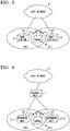
- Fig. 5 is a schematic diagram of CoMP using two base stations 4 and 5.
- Fig. 6 is a schematic diagram of CoMP using one central unit 1 and two distributed units 2-1 and 2-2.
- adjacent base stations 4 and 5 communicate with each other in coordination with a terminal device 6 located near the cell edge.
- the distributed units (base stations) 2-1 and 2-2 connected to the adjacent central unit 1 communicate with each other in coordination with the terminal device 6 located near the cell edge.
- Fig. 7 is a block diagram illustrating a system configuration of full centralization for performing CoMP processing.
- the number of distributed units is not necessarily limited to 2, and the number of antennas provided in one distributed unit may be two or more.
- a radio signal transmitted from a terminal device 6 is received by RF receiving units 22 of distributed units 302-1 and 302-2 via wireless transmission.
- a signal received by each of the distributed units 302-1 and 302-2 is subjected to signal conversion by a signal converting unit 23 and transmitted to a central unit 301. These signals are subjected to signal conversion by signal converting units 14 and 15 and supplied to an inter-base-station coordination processing unit 16.
- the inter-base-station coordination processing unit 16 performs CoMP processing on the supplied signals. Thereafter, the output of the inter-base-station coordination processing unit 16 is demodulated by the demodulation unit 17 and output to a decoding unit 18 as a soft decision value of a received signal.
- the decoding unit 18 decodes the soft decision value and outputs the decoded value as a hard decision value of the received signal to a host function unit 19.
- the host function unit 19 further transmits the hard decision value of the received signal to a host device.
- a transmission capacity between a distributed unit and a central unit is significantly large because transmission of a signal obtained by sampling and quantizing a signal received by the RF receiving unit 22 is performed.
- a necessary transmission rate between the distributed unit and the central unit is 1228 Mbps which is about 16 times 75 Mbps when communication of a wireless section is performed at a transmission rate of 75 Mbps.
- Fig. 8 is a block diagram illustrating a system configuration of partial centralization.
- the configuration illustrated in Fig. 8 can reduce the transmission capacity required between the central unit 401 and the distributed units 402-1 and 402-2.
- the number of distributed units is not necessarily limited to 2, and the number of antennas provided in one distributed unit may be two or more.
- a radio signal transmitted from the terminal device 6 is received by either the distributed unit 402-1 or the distributed unit 402-2 via wireless transmission.
- a signal from the terminal device 6 is received by the distributed unit 402-1.
- the distributed unit 402-1 demodulates the signal with the demodulation unit 24 and outputs the demodulated signal as a soft decision value of the received signal to the decoding unit 25.
- the decoding unit 25 decodes the soft decision value and outputs the decoded soft decision value as a hard decision value of the received signal to the signal converting unit 23.
- the signal converting unit 23 converts the signal into the hard decision value and transmits the hard decision value to the central unit 401.
- the central unit 401 performs signal conversion on the signal received by the signal converting unit 14, and transmits a hard decision value of the converted received signal to the host function unit 19.
- the host function unit 19 further transmits the hard decision value of the received signal to the host device.
- the present invention has been made in view of the above circumstances, and an objective of the present invention is to provide a wireless communication system and a wireless communication method capable of enabling coordination of communication between distributed units (base stations) while reducing a transmission capacity between a central unit and a distributed unit.
- the present invention is a wireless communication system comprising distributed unit equipment which wirelessly communicate with a terminal device and central unit equipment which is connected to the distributed unit equipment and receives and processes signals from the distributed unit equipment, the central unit equipment comprising: a host function unit configured to pre-notify the distributed unit equipment of whether or not a received signal from the terminal device is a target of coordination between distributed units; hard/soft determination units each configured to separate the received signals from the distributed unit equipment into a hard decision value and a soft decision value on the basis of presence or absence of coordination between the distributed units, transmit the hard decision value to the host function unit as it is, and transmit the soft decision value to a signal combining unit; the signal combining unit configured to combine soft decision values output from the hard/soft determination units and output a combined soft decision value; and a decoding unit configured to perform decoding using the soft decision value output from the signal combining unit, and the distributed unit equipment comprising: a switching decoding unit configured to output a received signal from the terminal device which is not a target of coordination between the distributed units as the hard
- the distributed unit equipment may increment or decrement the number of bits indicating the soft decision value output by the switching decoding unit according to an intensity of a received signal from the terminal device.
- the distributed unit equipment may perform weighting on a soft decision value output by the switching decoding unit according to an intensity of a received signal from the terminal device.
- the present invention is a wireless communication method to be performed by a wireless communication system including distributed unit equipment which wirelessly communicate with a terminal device and central unit equipment which is connected to the distributed unit equipment and receives and processes signals from the distributed unit equipment, the wireless communication method comprising: a host function step in which the central unit equipment pre-notify the distributed unit equipment of whether or not a received signal from the terminal device is a target of coordination between distributed units; a hard/soft determination step in which the central unit equipment separate the received signals from the distributed unit equipment into a hard decision value and a soft decision value on the basis of presence or absence of coordination between the distributed units, transmit the hard decision value to a host function unit as it is, and transmit the soft decision value to a signal combining unit; a signal combining step of combining the soft decision values output from the hard/soft determination step and outputting a combined soft decision value; a decoding step of performing a decoding process using the soft decision value output from the signal combining step; and a switching decoding step in which the distributed unit equipment output a received signal
- Fig. 1 is a block diagram illustrating a configuration of the first embodiment.
- parts the same as those of the conventional devices illustrated in Figs. 7 and 8 are denoted by the same reference signs, and description thereof will be omitted.
- the number of terminal devices 6 may be two or more, and the number of antennas of a terminal device 6 may be two or more.
- a distributed unit 102-1 is provided with a radio frequency (RF) receiving unit 22 connected to an antenna, a demodulation unit 24, a switching decoding unit 31, a multiplexing unit 32, and a signal converting unit 23. Because a distributed unit 102-2 has a configuration similar to that of the distributed unit 102-1, detailed description thereof will be omitted here.
- RF radio frequency
- a central unit 101 includes two signal converting units 14 and 15 which are equal in number to the number of distributed units, hard/soft determination units 41 and 42 respectively connected to the signal converting units 14 and 15, a signal combining unit 43 which combines soft decision values output by the hard/soft determination units 41 and 42, a decoding unit 44 which decodes an output of the signal combining unit 43, and a host function unit 45.
- the host function unit 45 of the central unit 101 pre-notifies the distributed units 102-1 and 102-2 of whether or not a signal transmitted from the terminal device 6 is a CoMP target.
- the transmitted signal is a CoMP target
- the signal transmitted from the terminal device 6 is received by both the distributed unit 102-1 and the distributed unit 102-2, and demodulated by the demodulation units 24 of the distributed units 102-1 and 102-2, so that a soft decision value of the received signal is obtained.
- the transmitted signal is not a CoMP target
- the signal transmitted from the terminal device 6 is received by the distributed unit 102-1 or the distributed unit 102-2 and demodulated by the demodulation unit 24 of one distributed unit, so that a soft decision value of the received signal is obtained.
- the switching decoding unit 31 switches a hard decision value output and a soft decision value output and supplies the hard decision value output and the soft decision value output to the multiplexing unit 32.
- the switching decoding unit 31 outputs a signal which is not a CoMP target as a hard decision value, and outputs a signal which is a CoMP target as a soft decision value.
- the multiplexing unit 32 performs time division multiplexing on the hard decision value and the soft decision value output from the switching decoding unit 31, the signal converting unit 23 converts a time division multiplexing result into a signal, and then the signal is transmitted to the central unit 101.
- the central unit 101 determines signals received through signal conversion by the signal converting units 14 and 15 as a hard decision value and a soft decision value and separates the hard decision value and the soft decision value in the hard/soft determination units 41 and 42. Furthermore, the central unit 101 transmits the hard decision value to the host function unit 45 as it is, and transmits the soft decision value to the signal combining unit 43.
- Soft decision values output from the hard/soft determination units 41 and 42 are combined by the signal combining unit 43 and then a combined soft decision value is transmitted to the decoding unit 44.
- the decoding unit 44 performs a decoding process on the basis of the input soft decision value, outputs a hard decision value of the received signal, and transmits the hard decision value to the host function unit 45.
- an interface such as an existing passive optical network (PON) may be used for signal conversion used for signal transmission between the distributed units 102-1 and 102-2 and the central unit 101, or a unique interface may be used.
- each of the distributed units 102-1 and 102-2 may perform a process of receiving a multicarrier signal such as orthogonal frequency-division multiplexing (OFDM) on the received signal after performing RF reception from the terminal device 6.
- OFDM orthogonal frequency-division multiplexing
- the switching decoding unit 31 may increase or decrease the number of bits representing a soft decision value to be output in accordance with an intensity of a received signal from the terminal device. Thereby, a transmission capacity between the central unit and the distributed unit can be further suppressed.
- the switching decoding unit 31 may perform weighting on the soft decision value to be output according to the intensity of the received signal from the terminal device. This makes it possible to perform coordination for CoMP processing among a plurality of distributed units with higher performance.
- Fig. 2 is a block diagram illustrating the configuration of the second embodiment.
- parts the same as those of the wireless communication system according to the first embodiment illustrated in Fig. 1 are denoted by the same reference signs, and description thereof will be omitted.
- the wireless communication system is different from the wireless communication system illustrated in Fig. 1 in that the number of terminal devices 6, the number of antennas of each terminal device, the number of distributed units, and the number of antennas of each distributed unit may be any number.
- the number of terminal devices is M (M is a natural number) and the number of distributed units is N (N is a natural number).
- Signals transmitted from terminal devices 6-1 to 6-M are received by RF receiving units 22 of distributed units 202-1 to 202-N through wireless transmission.
- a demodulation unit 33 of each distributed unit obtains a soft decision value of a received signal.
- the demodulation unit 33 also performs a signal reception process based on a plurality of antennas such as multiple-input multiple-output (MIMO).
- MIMO multiple-input multiple-output
- a host function unit 45 of a central unit 201 pre-notifies each of the distributed units 202-1 to 202-N of whether or not signals received from the terminal devices 6-1 to 6-M are CoMP targets.
- a process of a switching decoding unit 34 on a soft decision value obtained by the demodulation unit 33 is similar to that of the first embodiment. If received signals received from the terminal devices 6-1 to 6-M are not CoMP targets, the received signals are output as hard decision values from switching decoding units 34 of the distributed units 202-1 to 202-N and transmitted to the central unit 201 via a multiplexing unit 32 and a signal converting unit 23. The hard decision values received by the central unit 201 are determined and separated by hard/soft determination units 41 and 42 of the central unit 201 and transmitted to the host function unit 45.
- the received signals received from the terminal devices 6-1 to 6-M are CoMP targets, the received signals are output as soft decision values from the switching decoding units 34 of the distributed units 202-1 to 202-N and transmitted to the central unit 201 via the multiplexing unit 32 and the signal converting unit 23.
- the soft decision values received by the central unit 201 are determined and separated by the hard/soft determination units 41 and 42 of the central unit 201 and transmitted to the signal combining unit 43.
- the soft decision values input to the signal combining unit 43 are combined and transmitted to the decoding unit 44.
- the decoding unit 44 performs a decoding process on the basis of the input soft decision value and transmits a hard decision value of the received signal to the host function unit 45.
- an interface such as an existing PON may be used for signal conversion used for signal transmission between the distributed units 202-1 to 202-N and the central unit 1 or a unique interface may be used.
- each distributed unit may perform a process of receiving a multicarrier signal such as OFDM on the received signal after performing RF reception from the terminal device 6.
- the switching decoding unit 34 illustrated in Fig. 2 may increase or decrease the number of bits representing a soft decision value to be output in accordance with an intensity of a received signal from the terminal device. Thereby, a transmission capacity between the central unit and the distributed unit can be further suppressed.
- the switching decoding unit 34 may perform weighting on the soft decision value to be output according to the intensity of the received signal from the terminal device. This makes it possible to perform coordination for CoMP processing among a plurality of distributed units with higher performance.
- a mobile communication (wireless communication) system including a central unit and a plurality of distributed units, it is possible to perform a process of eliminating signal interference between distributed units even when a system configuration based on partial centralization in which functions of the antenna unit and the physical layer are cut out is used in the distributed unit.
- the transmission capacity between the distributed unit and the central unit can be reduced, and soft decision values are transmitted between the distributed unit and the central unit in the system configuration based on partial centralization in which CoMP processing cannot be performed.
- the CoMP processing can be implemented.
- a transmission capacity between the distributed unit and the central unit can be reduced by transmitting a received signal which is not a CoMP target as a hard decision value without transmitting all signals as soft decision values between the distributed unit and the central unit. For example, if the distributed unit receives a radio signal of 1 Gbps and the number of bits of quantization of the soft decision value is 5, a transmission capacity between the distributed unit and the central unit in a conventional scheme becomes 5 Gbps.
- the transmission capacity between the distributed unit and the central unit is 3 Gbps in total, which is 40% lower than in the conventional scheme.
- a terminal device, a distributed unit, and a central unit in the above-described embodiments may be implemented by a computer.
- these may be implemented by recording a program for implementing functions thereof on a computer-readable recording medium and causing a computer system to read and execute the program recorded on the recording medium.
- the "computer system” described here is assumed to include an operating system (OS) and hardware such as peripheral devices.
- the "computer-readable recording medium” refers to a storage device including a flexible disk, a magneto-optical disc, a read only memory (ROM), a portable medium such as a compact disc (CD)-ROM, and a hard disk embedded in the computer system.
- the "computer-readable recording medium” may include a computer-readable recording medium for dynamically holding a program for a short time as in a communication line when the program is transmitted via a network such as the Internet or a communication circuit such as a telephone circuit and a computer-readable recording medium for holding the program for a predetermined time as in a volatile memory inside the computer system including a server and a client when the program is transmitted.
- the above-described program may be a program for implementing some of the above-described functions.
- the above-described program may be a program capable of implementing the above-described functions in combination with a program already recorded on the computer system or may be a program implemented using hardware such as a programmable logic device (PLD) or a field programmable gate array (FPGA).
- PLD programmable logic device
- FPGA field programmable gate array
- a wireless communication system and a wireless communication method of the present invention can be applied to a field of application which is essential to enable coordination between distributed units (base stations) while reducing a transmission capacity between a central unit and a distributed unit.
Landscapes
- Engineering & Computer Science (AREA)
- Signal Processing (AREA)
- Computer Networks & Wireless Communication (AREA)
- Quality & Reliability (AREA)
- Mobile Radio Communication Systems (AREA)
Abstract
Description
- The present invention relates to a wireless communication system which physically extends some functions of a base station and uses the base station as a distributed unit.
- Priority is claimed on Japanese Patent Application No.
2015-43880, filed March 05, 2015 - A system configuration in which a plurality of distributed units equipped with some of base station functions are extended in a wireless communication system, particularly a mobile communication system, has been studied. A base station obtained by extending a distributed unit has a function of controlling a plurality of distributed units as a central unit. In a communication scheme of performing communication between the central unit and the distributed units, two system configurations such as full centralization and partial centralization, which differ in a function distribution between the central unit and the distributed unit, are being studied.
-
Fig. 3 is a block diagram illustrating a system configuration of full centralization. In the system configuration of full centralization, as illustrated inFig. 3 , thecentral unit 301 is equipped with a physicallayer function unit 11 from which an antenna unit is excluded and afunctional unit 12 of a data link layer or a higher layer. Also, in the system configuration, n (n is a natural number) distributed units 302-1 to 302-n equipped with only anantenna unit 21 are extended. -
Fig. 4 is a block diagram illustrating a system configuration of partial centralization. In the system configuration of partial centralization, thefunctional unit 12 of the data link layer or the higher layer and somefunctions 13 of physical layer functions are installed in thecentral unit 401 as illustrated inFig. 4 . Also, in the system configuration, distributed units 402-1 to 402-n equipped with somefunctions 22 of the physical layer functions are extended (for example, see Non-Patent Document 1). - Also, in a communication system, error correction code technology for correcting an error in a transmission path by assigning redundant bits to a signal bit sequence to be transmitted is known (for example, see Non-Patent Document 2). In this error correction code technology, a signal bit sequence to which a redundant bit is assigned by a transmission device is modulated into any form, transmitted through a transmission path, and received by a reception device. At this time, when the received modulated signal is demodulated, a process of determining whether a signal bit is 0 or 1 on the basis of a certain threshold value and outputting a determination result as a received bit sequence is called hard decision, and its output is called a hard decision value.
- On the other hand, when the modulated signal is demodulated, outputting the demodulated signal as a received signal with a likelihood value of a signal bit of 0 or 1 is called a soft decision output, and its output is called a soft decision value. A received signal output as a hard decision value or a soft decision value is output as a final received bit sequence by a decoder. Among decoders, a decoder can select whether an output is a hard decision value or a soft decision value as in a turbo decoder.
- On the other hand, an area covered by one base station in a mobile communication system is referred to as a cell, and the coverage area thereof generally overlaps between adjacent cells. Thus, when a terminal device is located near a cell edge, a phenomenon that a radio signal transmitted from the terminal device to a desired base station and a radio signal transmitted from the terminal device belonging to an adjacent base station interfere with each other and a transmission rate between the terminal device and the base station is significantly degraded becomes a problem. Coordinated multi-point transmission/reception (CoMP) technology (see, for example, Non-Patent Document 3) has been studied as means for solving the problem of inter-cell signal interference.
-
Fig. 5 is a schematic diagram of CoMP using twobase stations Fig. 6 is a schematic diagram of CoMP using one central unit 1 and two distributed units 2-1 and 2-2. - As illustrated in
Fig. 5 , in CoMP,adjacent base stations terminal device 6 located near the cell edge. InFig. 6 , the distributed units (base stations) 2-1 and 2-2 connected to the adjacent central unit 1 communicate with each other in coordination with theterminal device 6 located near the cell edge. -
- [Non-Patent Document 1]
Proc. EuCNC 2014, pp. 1-5, "Towards a Flexible Functional Split for Cloud-RAN Networks," Jun. 2014. - [Non-Patent Document 2]
Journal of the Institute of Electronics, Information and Communication Engineers Vol. 90, No. 7, "Communication Technology: Basic Knowledge and its trend [III]: Error-Correction Coding," Jul. 2007. - [Non-Patent Document 3]
IEEE Communications Magazine, Vol. 50, No. 11, pp. 44-50, "Coordinated Multipoint Transmission and Reception in LTE-Advanced Systems," Nov. 2012. -
Fig. 7 is a block diagram illustrating a system configuration of full centralization for performing CoMP processing. Here, the number of distributed units is not necessarily limited to 2, and the number of antennas provided in one distributed unit may be two or more. - A radio signal transmitted from a
terminal device 6 is received byRF receiving units 22 of distributed units 302-1 and 302-2 via wireless transmission. A signal received by each of the distributed units 302-1 and 302-2 is subjected to signal conversion by asignal converting unit 23 and transmitted to acentral unit 301. These signals are subjected to signal conversion bysignal converting units coordination processing unit 16. The inter-base-stationcoordination processing unit 16 performs CoMP processing on the supplied signals. Thereafter, the output of the inter-base-stationcoordination processing unit 16 is demodulated by thedemodulation unit 17 and output to adecoding unit 18 as a soft decision value of a received signal. Thedecoding unit 18 decodes the soft decision value and outputs the decoded value as a hard decision value of the received signal to ahost function unit 19. Thehost function unit 19 further transmits the hard decision value of the received signal to a host device. - In the signal transmission in such a system configuration of full centralization, there is a problem in that a transmission capacity between a distributed unit and a central unit is significantly large because transmission of a signal obtained by sampling and quantizing a signal received by the
RF receiving unit 22 is performed. For example, if a common public radio interface (CPRI) is used for signal transmission, a necessary transmission rate between the distributed unit and the central unit is 1228 Mbps which is about 16 times 75 Mbps when communication of a wireless section is performed at a transmission rate of 75 Mbps. -
Fig. 8 is a block diagram illustrating a system configuration of partial centralization. - Compared with the system configuration of full centralization illustrated in
Fig. 7 , the configuration illustrated inFig. 8 can reduce the transmission capacity required between thecentral unit 401 and the distributed units 402-1 and 402-2. Here, the number of distributed units is not necessarily limited to 2, and the number of antennas provided in one distributed unit may be two or more. A radio signal transmitted from theterminal device 6 is received by either the distributed unit 402-1 or the distributed unit 402-2 via wireless transmission. - In the system configuration illustrated in
Fig. 8 , as an example, a signal from theterminal device 6 is received by the distributed unit 402-1. After the signal from theterminal device 6 is received by theRF receiving unit 22, the distributed unit 402-1 demodulates the signal with thedemodulation unit 24 and outputs the demodulated signal as a soft decision value of the received signal to thedecoding unit 25. Thedecoding unit 25 decodes the soft decision value and outputs the decoded soft decision value as a hard decision value of the received signal to thesignal converting unit 23. Thesignal converting unit 23 converts the signal into the hard decision value and transmits the hard decision value to thecentral unit 401. Thecentral unit 401 performs signal conversion on the signal received by thesignal converting unit 14, and transmits a hard decision value of the converted received signal to thehost function unit 19. Thehost function unit 19 further transmits the hard decision value of the received signal to the host device. - Because physical layer functions such as demodulation and decoding are distributed in the system configuration of partial centralization as described above, CoMP processing requiring a signal before demodulation cannot be performed. That is, because only one of the distributed unit 402-1 and the distributed unit 402-2 can receive a signal from the
terminal device 6, there is a problem in that it is impossible to perform the CoMP processing which is possible in the system of full centralization illustrated inFig. 7 . - The present invention has been made in view of the above circumstances, and an objective of the present invention is to provide a wireless communication system and a wireless communication method capable of enabling coordination of communication between distributed units (base stations) while reducing a transmission capacity between a central unit and a distributed unit.
- The present invention is a wireless communication system comprising distributed unit equipment which wirelessly communicate with a terminal device and central unit equipment which is connected to the distributed unit equipment and receives and processes signals from the distributed unit equipment, the central unit equipment comprising: a host function unit configured to pre-notify the distributed unit equipment of whether or not a received signal from the terminal device is a target of coordination between distributed units; hard/soft determination units each configured to separate the received signals from the distributed unit equipment into a hard decision value and a soft decision value on the basis of presence or absence of coordination between the distributed units, transmit the hard decision value to the host function unit as it is, and transmit the soft decision value to a signal combining unit; the signal combining unit configured to combine soft decision values output from the hard/soft determination units and output a combined soft decision value; and a decoding unit configured to perform decoding using the soft decision value output from the signal combining unit, and the distributed unit equipment comprising: a switching decoding unit configured to output a received signal from the terminal device which is not a target of coordination between the distributed units as the hard decision value and output a received signal from the terminal device serving as the target of the coordination between the distributed units as the soft decision value on the basis of the presence or absence of the coordination between the distributed units for which the notification is provided from the host function unit.
- In the wireless communication system of the present invention, the distributed unit equipment may increment or decrement the number of bits indicating the soft decision value output by the switching decoding unit according to an intensity of a received signal from the terminal device.
- In the wireless communication system of the present invention, the distributed unit equipment may perform weighting on a soft decision value output by the switching decoding unit according to an intensity of a received signal from the terminal device.
- The present invention is a wireless communication method to be performed by a wireless communication system including distributed unit equipment which wirelessly communicate with a terminal device and central unit equipment which is connected to the distributed unit equipment and receives and processes signals from the distributed unit equipment, the wireless communication method comprising: a host function step in which the central unit equipment pre-notify the distributed unit equipment of whether or not a received signal from the terminal device is a target of coordination between distributed units; a hard/soft determination step in which the central unit equipment separate the received signals from the distributed unit equipment into a hard decision value and a soft decision value on the basis of presence or absence of coordination between the distributed units, transmit the hard decision value to a host function unit as it is, and transmit the soft decision value to a signal combining unit; a signal combining step of combining the soft decision values output from the hard/soft determination step and outputting a combined soft decision value; a decoding step of performing a decoding process using the soft decision value output from the signal combining step; and a switching decoding step in which the distributed unit equipment output a received signal from the terminal device which is not a target of coordination between the distributed units as the hard decision value and output a received signal from the terminal device serving as the target of the coordination between the distributed units as the soft decision value on the basis of the presence or absence of the coordination between the distributed units for which the notification is provided from the host function unit.
- According to the present invention, there is an advantageous effect in that a transmission capacity between a central unit and a distributed unit is reduced and coordination of communication between distributed units (base stations) is enabled.
-
-
Fig. 1 is a block diagram illustrating a configuration of a wireless communication system according to a first embodiment of the present invention. -
Fig. 2 is a block diagram illustrating a configuration of a wireless communication system according to a second embodiment of the present invention. -
Fig. 3 is a block diagram illustrating a system configuration of full centralization in conventional technology. -
Fig. 4 is a block diagram illustrating a system configuration of partial centralization in conventional technology. -
Fig. 5 is a diagram illustrating CoMP processing by two base stations in conventional technology. -
Fig. 6 is a diagram illustrating CoMP processing by a central unit and a distributed unit in conventional technology. -
Fig. 7 is a block diagram illustrating a specific example of a system of full centralization in conventional technology. -
Fig. 8 is a block diagram illustrating a specific example of a system of partial centralization in conventional technology. - Hereinafter, a wireless communication system according to the first embodiment of the present invention will be described with reference to the drawings.
Fig. 1 is a block diagram illustrating a configuration of the first embodiment. InFig. 1 , parts the same as those of the conventional devices illustrated inFigs. 7 and8 are denoted by the same reference signs, and description thereof will be omitted. It is not necessary to limit the number of distributed units to 2, and the number of antennas provided in one distributed unit may be two or more. Also, the number ofterminal devices 6 may be two or more, and the number of antennas of aterminal device 6 may be two or more. - A distributed unit 102-1 is provided with a radio frequency (RF) receiving
unit 22 connected to an antenna, ademodulation unit 24, a switchingdecoding unit 31, a multiplexingunit 32, and asignal converting unit 23. Because a distributed unit 102-2 has a configuration similar to that of the distributed unit 102-1, detailed description thereof will be omitted here. - A
central unit 101 includes twosignal converting units soft determination units signal converting units signal combining unit 43 which combines soft decision values output by the hard/soft determination units decoding unit 44 which decodes an output of thesignal combining unit 43, and ahost function unit 45. - Next, the operation of the wireless communication system illustrated in
Fig. 1 will be described. First, thehost function unit 45 of thecentral unit 101 pre-notifies the distributed units 102-1 and 102-2 of whether or not a signal transmitted from theterminal device 6 is a CoMP target. - Next, if the transmitted signal is a CoMP target, the signal transmitted from the
terminal device 6 is received by both the distributed unit 102-1 and the distributed unit 102-2, and demodulated by thedemodulation units 24 of the distributed units 102-1 and 102-2, so that a soft decision value of the received signal is obtained. If the transmitted signal is not a CoMP target, the signal transmitted from theterminal device 6 is received by the distributed unit 102-1 or the distributed unit 102-2 and demodulated by thedemodulation unit 24 of one distributed unit, so that a soft decision value of the received signal is obtained. - Next, on the basis of information of the presence or absence of CoMP for which a notification is provided from the
host function unit 45 of thecentral unit 101, the switchingdecoding unit 31 switches a hard decision value output and a soft decision value output and supplies the hard decision value output and the soft decision value output to themultiplexing unit 32. The switchingdecoding unit 31 outputs a signal which is not a CoMP target as a hard decision value, and outputs a signal which is a CoMP target as a soft decision value. - The multiplexing
unit 32 performs time division multiplexing on the hard decision value and the soft decision value output from the switchingdecoding unit 31, thesignal converting unit 23 converts a time division multiplexing result into a signal, and then the signal is transmitted to thecentral unit 101. On the basis of information of presence or absence of CoMP for which a notification is provided from thehost function unit 45, thecentral unit 101 determines signals received through signal conversion by thesignal converting units soft determination units central unit 101 transmits the hard decision value to thehost function unit 45 as it is, and transmits the soft decision value to thesignal combining unit 43. - Soft decision values output from the hard/
soft determination units signal combining unit 43 and then a combined soft decision value is transmitted to thedecoding unit 44. Thedecoding unit 44 performs a decoding process on the basis of the input soft decision value, outputs a hard decision value of the received signal, and transmits the hard decision value to thehost function unit 45. - Also, an interface such as an existing passive optical network (PON) may be used for signal conversion used for signal transmission between the distributed units 102-1 and 102-2 and the
central unit 101, or a unique interface may be used. Also, each of the distributed units 102-1 and 102-2 may perform a process of receiving a multicarrier signal such as orthogonal frequency-division multiplexing (OFDM) on the received signal after performing RF reception from theterminal device 6. - Also, the switching
decoding unit 31 may increase or decrease the number of bits representing a soft decision value to be output in accordance with an intensity of a received signal from the terminal device. Thereby, a transmission capacity between the central unit and the distributed unit can be further suppressed. - Also, the switching
decoding unit 31 may perform weighting on the soft decision value to be output according to the intensity of the received signal from the terminal device. This makes it possible to perform coordination for CoMP processing among a plurality of distributed units with higher performance. - Next, a wireless communication system according to the second embodiment of the present invention will be described with reference to the drawings.
Fig. 2 is a block diagram illustrating the configuration of the second embodiment. InFig. 2 , parts the same as those of the wireless communication system according to the first embodiment illustrated inFig. 1 are denoted by the same reference signs, and description thereof will be omitted. As illustrated inFig. 2 , the wireless communication system is different from the wireless communication system illustrated inFig. 1 in that the number ofterminal devices 6, the number of antennas of each terminal device, the number of distributed units, and the number of antennas of each distributed unit may be any number. - Here, the number of terminal devices is M (M is a natural number) and the number of distributed units is N (N is a natural number). Signals transmitted from terminal devices 6-1 to 6-M are received by
RF receiving units 22 of distributed units 202-1 to 202-N through wireless transmission. Ademodulation unit 33 of each distributed unit obtains a soft decision value of a received signal. Here, thedemodulation unit 33 also performs a signal reception process based on a plurality of antennas such as multiple-input multiple-output (MIMO). - Next, the operation of the wireless communication system illustrated in
Fig. 2 will be described. - First, a
host function unit 45 of acentral unit 201 pre-notifies each of the distributed units 202-1 to 202-N of whether or not signals received from the terminal devices 6-1 to 6-M are CoMP targets. - A process of a switching
decoding unit 34 on a soft decision value obtained by thedemodulation unit 33 is similar to that of the first embodiment. If received signals received from the terminal devices 6-1 to 6-M are not CoMP targets, the received signals are output as hard decision values from switchingdecoding units 34 of the distributed units 202-1 to 202-N and transmitted to thecentral unit 201 via amultiplexing unit 32 and asignal converting unit 23. The hard decision values received by thecentral unit 201 are determined and separated by hard/soft determination units central unit 201 and transmitted to thehost function unit 45. - If the received signals received from the terminal devices 6-1 to 6-M are CoMP targets, the received signals are output as soft decision values from the switching
decoding units 34 of the distributed units 202-1 to 202-N and transmitted to thecentral unit 201 via themultiplexing unit 32 and thesignal converting unit 23. The soft decision values received by thecentral unit 201 are determined and separated by the hard/soft determination units central unit 201 and transmitted to thesignal combining unit 43. The soft decision values input to thesignal combining unit 43 are combined and transmitted to thedecoding unit 44. Thedecoding unit 44 performs a decoding process on the basis of the input soft decision value and transmits a hard decision value of the received signal to thehost function unit 45. - Also, an interface such as an existing PON may be used for signal conversion used for signal transmission between the distributed units 202-1 to 202-N and the central unit 1 or a unique interface may be used. Also, each distributed unit may perform a process of receiving a multicarrier signal such as OFDM on the received signal after performing RF reception from the
terminal device 6. - Also, the switching
decoding unit 34 illustrated inFig. 2 may increase or decrease the number of bits representing a soft decision value to be output in accordance with an intensity of a received signal from the terminal device. Thereby, a transmission capacity between the central unit and the distributed unit can be further suppressed. - Also, the switching
decoding unit 34 may perform weighting on the soft decision value to be output according to the intensity of the received signal from the terminal device. This makes it possible to perform coordination for CoMP processing among a plurality of distributed units with higher performance. - Thus, in a mobile communication (wireless communication) system including a central unit and a plurality of distributed units, it is possible to perform a process of eliminating signal interference between distributed units even when a system configuration based on partial centralization in which functions of the antenna unit and the physical layer are cut out is used in the distributed unit.
- In the system configuration based on partial centralization, because data transmitted between the central unit and the distributed unit becomes a bit sequence after decoding is performed, a transmission capacity between the central unit and the distributed unit is significantly smaller than in the case of full centralization. However, in the system configuration based on partial centralization, the functions of the physical layer are distributed, and coordination between the base stations using both of the received signals received by the two distributed units cannot be made.
- In the present embodiment, the transmission capacity between the distributed unit and the central unit can be reduced, and soft decision values are transmitted between the distributed unit and the central unit in the system configuration based on partial centralization in which CoMP processing cannot be performed. By combining the soft decision values, the CoMP processing can be implemented.
- Furthermore, a transmission capacity between the distributed unit and the central unit can be reduced by transmitting a received signal which is not a CoMP target as a hard decision value without transmitting all signals as soft decision values between the distributed unit and the central unit. For example, if the distributed unit receives a radio signal of 1 Gbps and the number of bits of quantization of the soft decision value is 5, a transmission capacity between the distributed unit and the central unit in a conventional scheme becomes 5 Gbps.
- On the other hand, if the number of received signals serving as CoMP targets is half of the total, a radio signal of 0.5 Gbps in radio signals of 1 Gbps is transmitted as a hard decision value at 0.5 Gbps and the remaining radio signal of 0.5 Gbps is transmitted as a soft decision value at 2.5 Gbps in the present embodiment. Consequently, in the present embodiment, the transmission capacity between the distributed unit and the central unit is 3 Gbps in total, which is 40% lower than in the conventional scheme.
- Some or all of a terminal device, a distributed unit, and a central unit in the above-described embodiments may be implemented by a computer. In this case, these may be implemented by recording a program for implementing functions thereof on a computer-readable recording medium and causing a computer system to read and execute the program recorded on the recording medium. Also, the "computer system" described here is assumed to include an operating system (OS) and hardware such as peripheral devices. Also, the "computer-readable recording medium" refers to a storage device including a flexible disk, a magneto-optical disc, a read only memory (ROM), a portable medium such as a compact disc (CD)-ROM, and a hard disk embedded in the computer system. Furthermore, the "computer-readable recording medium" may include a computer-readable recording medium for dynamically holding a program for a short time as in a communication line when the program is transmitted via a network such as the Internet or a communication circuit such as a telephone circuit and a computer-readable recording medium for holding the program for a predetermined time as in a volatile memory inside the computer system including a server and a client when the program is transmitted. Also, the above-described program may be a program for implementing some of the above-described functions. Further, the above-described program may be a program capable of implementing the above-described functions in combination with a program already recorded on the computer system or may be a program implemented using hardware such as a programmable logic device (PLD) or a field programmable gate array (FPGA).
- While embodiments of the invention have been described above with reference to the drawings, it should be understood that these are exemplary of the invention and are not to be considered as limiting. Additions, omissions, substitutions, and other modifications of components can be made without departing from the spirit or scope of the present invention.
- A wireless communication system and a wireless communication method of the present invention can be applied to a field of application which is essential to enable coordination between distributed units (base stations) while reducing a transmission capacity between a central unit and a distributed unit.
-
- 101, 201
- Central unit
- 14, 15
- Signal converting unit
- 41, 42
- Hard/soft determination unit
- 43
- Signal combining unit
- 44
- Decoding unit
- 45
- Host function unit
- 102-1 to 102-N, 202-1 to 202-N
- Distributed unit (base station)
- 22
- RF receiving unit
- 23
- Signal converting unit
- 24
- Demodulation unit
- 31
- Switching decoding unit
- 32
- Multiplexing unit
- 33
- Demodulation unit
- 34
- Switching decoding unit
- 6, 6-1 to 6-M
- Terminal device
Claims (4)
- A wireless communication system comprising distributed unit equipment which wirelessly communicate with a terminal device and central unit equipment which is connected to the distributed unit equipment and receives and processes signals from the distributed unit equipment,
the central unit equipment comprising:a host function unit configured to pre-notify the distributed unit equipment of whether or not a received signal from the terminal device is a target of coordination between distributed units;hard/soft determination units each configured to separate the received signals from the distributed unit equipment into a hard decision value and a soft decision value on the basis of presence or absence of coordination between the distributed units, transmit the hard decision value to the host function unit as it is, and transmit the soft decision value to a signal combining unit;the signal combining unit configured to combine soft decision values output from the hard/soft determination units and output a combined soft decision value; anda decoding unit configured to perform decoding using the soft decision value output from the signal combining unit, andthe distributed unit equipment comprising:a switching decoding unit configured to output a received signal from the terminal device which is not a target of coordination between the distributed units as the hard decision value and output a received signal from the terminal device serving as the target of the coordination between the distributed units as the soft decision value on the basis of the presence or absence of the coordination between the distributed units for which the notification is provided from the host function unit. - The wireless communication system according to claim 1, wherein the distributed unit equipment increments or decrements the number of bits indicating the soft decision value output by the switching decoding unit according to an intensity of a received signal from the terminal device.
- The wireless communication system according to claim 1, wherein the distributed unit equipment perform weighting on a soft decision value output by the switching decoding unit according to an intensity of a received signal from the terminal device.
- A wireless communication method to be performed by a wireless communication system including distributed unit equipment which wirelessly communicate with a terminal device and central unit equipment which is connected to the distributed unit equipment and receives and processes signals from the distributed unit equipment, the wireless communication method comprising:a host function step in which the central unit equipment pre-notify the distributed unit equipment of whether or not a received signal from the terminal device is a target of coordination between distributed units;a hard/soft determination step in which the central unit equipment separate the received signals from the distributed unit equipment into a hard decision value and a soft decision value on the basis of presence or absence of coordination between the distributed units, transmit the hard decision value to a host function unit as it is, and transmit the soft decision value to a signal combining unit;a signal combining step in which the central unit equipment combine the soft decision values output from the hard/soft determination step and output a combined soft decision value;a decoding step of performing a decoding process using the soft decision value output from the signal combining step; anda switching decoding step in which the distributed unit equipment output a received signal from the terminal device which is not a target of coordination between the distributed units as the hard decision value and output a received signal from the terminal device serving as the target of the coordination between the distributed units as the soft decision value on the basis of the presence or absence of the coordination between the distributed units for which the notification is provided from the host function unit.
Applications Claiming Priority (2)
| Application Number | Priority Date | Filing Date | Title |
|---|---|---|---|
| JP2015043880 | 2015-03-05 | ||
| PCT/JP2016/056570 WO2016140303A1 (en) | 2015-03-05 | 2016-03-03 | Wireless communication system and wireless communication method |
Publications (2)
| Publication Number | Publication Date |
|---|---|
| EP3249827A1 true EP3249827A1 (en) | 2017-11-29 |
| EP3249827A4 EP3249827A4 (en) | 2018-10-17 |
Family
ID=56848275
Family Applications (1)
| Application Number | Title | Priority Date | Filing Date |
|---|---|---|---|
| EP16758995.1A Withdrawn EP3249827A4 (en) | 2015-03-05 | 2016-03-03 | Wireless communication system and wireless communication method |
Country Status (5)
| Country | Link |
|---|---|
| US (1) | US10211956B2 (en) |
| EP (1) | EP3249827A4 (en) |
| JP (1) | JP6283450B2 (en) |
| CN (1) | CN107408973B (en) |
| WO (1) | WO2016140303A1 (en) |
Cited By (1)
| Publication number | Priority date | Publication date | Assignee | Title |
|---|---|---|---|---|
| EP3515026A4 (en) * | 2016-11-11 | 2020-04-29 | Nippon Telegraph and Telephone Corporation | RADIOCOMMUNICATION SYSTEM AND RADIOCOMMUNICATION METHOD |
Families Citing this family (5)
| Publication number | Priority date | Publication date | Assignee | Title |
|---|---|---|---|---|
| CN108616933A (en) * | 2017-01-24 | 2018-10-02 | 电信科学技术研究院 | Communication processing method and device under a kind of central location-distributed unit framework |
| CN108632869B (en) * | 2017-03-22 | 2023-02-17 | 中兴通讯股份有限公司 | A transmission control method and device |
| JP2019009635A (en) * | 2017-06-26 | 2019-01-17 | 日本電信電話株式会社 | Wireless communication system and wireless communication method |
| JP7434022B2 (en) * | 2020-03-27 | 2024-02-20 | 株式会社Nttドコモ | Communication device and communication method |
| JP7051990B1 (en) | 2020-12-03 | 2022-04-11 | ソフトバンク株式会社 | Mobile communication system and inter-base station cooperation control device |
Family Cites Families (18)
| Publication number | Priority date | Publication date | Assignee | Title |
|---|---|---|---|---|
| JP2616440B2 (en) * | 1994-05-31 | 1997-06-04 | 日本電気株式会社 | Soft decision circuit |
| EP1213852A1 (en) * | 2000-07-24 | 2002-06-12 | Mitsubishi Denki Kabushiki Kaisha | Receiving apparatus and receiving method for radio communication |
| FR2821517B1 (en) * | 2001-02-23 | 2004-03-19 | Nortel Networks Ltd | COMMUNICATION METHOD, RADIO NETWORK CONTROLLER AND BASE NODE FOR CARRYING OUT THIS METHOD |
| JP4000067B2 (en) | 2003-01-30 | 2007-10-31 | 三洋電機株式会社 | Receiving method and apparatus |
| US7746816B2 (en) * | 2003-03-13 | 2010-06-29 | Qualcomm Incorporated | Method and system for a power control in a communication system |
| EP1700396A1 (en) * | 2003-12-23 | 2006-09-13 | Telefonaktiebolaget LM Ericsson (publ) | Information transfer method and system |
| CN101047462A (en) * | 2006-03-27 | 2007-10-03 | 上海宇梦通信科技有限公司 | Broadband CDMA multiple carrier frequency selecting method based on OVSF code |
| IL181398A0 (en) * | 2007-02-18 | 2007-12-03 | Runcom Technologies Ltd | Mimo decoding system and method |
| CN101155419A (en) * | 2007-07-02 | 2008-04-02 | 重庆邮电大学 | TD-SCDMA mobile phone terminal supporting AGPS and positioning processing method |
| CN101360307A (en) * | 2007-08-03 | 2009-02-04 | 上海虹鹰通信技术有限公司 | Network protocol simulation method and device in third generation mobile communication system |
| EP2476219A1 (en) * | 2009-09-10 | 2012-07-18 | Fujitsu Limited | Cell selection for mimo transmission |
| JP5421299B2 (en) * | 2011-01-07 | 2014-02-19 | 株式会社Nttドコモ | Mobile terminal apparatus, radio base station apparatus, and radio communication method |
| JP2012239019A (en) * | 2011-05-11 | 2012-12-06 | Ntt Docomo Inc | Wireless base station device, mobile terminal device, wireless communication method, and wireless communication system |
| WO2013012264A2 (en) * | 2011-07-19 | 2013-01-24 | 엘지전자 주식회사 | Communication method using multiple transmission points, and apparatus for same |
| KR102157188B1 (en) * | 2013-02-15 | 2020-09-17 | 삼성전자주식회사 | Mobile terminal handover in an lte network |
| JP6053159B2 (en) | 2013-05-24 | 2016-12-27 | 日本電信電話株式会社 | Wireless communication system, distributed station apparatus, and communication method |
| US9503203B2 (en) * | 2013-06-11 | 2016-11-22 | Intel Corporation | Wireless interference cancellation |
| EP3029847B1 (en) * | 2013-07-29 | 2021-05-12 | LG Electronics Inc. | Nib comp transmission method and device in wireless communication system |
-
2016
- 2016-03-03 US US15/552,724 patent/US10211956B2/en active Active
- 2016-03-03 CN CN201680013056.8A patent/CN107408973B/en active Active
- 2016-03-03 JP JP2017503709A patent/JP6283450B2/en active Active
- 2016-03-03 EP EP16758995.1A patent/EP3249827A4/en not_active Withdrawn
- 2016-03-03 WO PCT/JP2016/056570 patent/WO2016140303A1/en not_active Ceased
Cited By (1)
| Publication number | Priority date | Publication date | Assignee | Title |
|---|---|---|---|---|
| EP3515026A4 (en) * | 2016-11-11 | 2020-04-29 | Nippon Telegraph and Telephone Corporation | RADIOCOMMUNICATION SYSTEM AND RADIOCOMMUNICATION METHOD |
Also Published As
| Publication number | Publication date |
|---|---|
| JPWO2016140303A1 (en) | 2017-10-05 |
| US10211956B2 (en) | 2019-02-19 |
| WO2016140303A1 (en) | 2016-09-09 |
| JP6283450B2 (en) | 2018-02-21 |
| CN107408973A (en) | 2017-11-28 |
| EP3249827A4 (en) | 2018-10-17 |
| US20180048439A1 (en) | 2018-02-15 |
| CN107408973B (en) | 2021-09-14 |
Similar Documents
| Publication | Publication Date | Title |
|---|---|---|
| US10211956B2 (en) | Wireless communication system and wireless communication method | |
| CN110235388B (en) | Bandwidth reduction using beamforming and data compression | |
| US20210045113A1 (en) | Method and device used for wireless communication in ue and base station | |
| CN106162851A (en) | The communication means of a kind of multi-user's superposition and device | |
| EP3972144A1 (en) | Base station apparatus, wireless communication system, and communication method | |
| CN109756299B (en) | Method and device in user equipment and base station for wireless communication | |
| EP3091775B1 (en) | Base station device, wireless communication system, and communication method | |
| US10666337B2 (en) | Radio apparatus and radio communication method | |
| US11546024B2 (en) | System and method for dynamic single-radio and dual-radio mode selection for DL MU-MIMO | |
| EP3515026B1 (en) | Remote radio head comprising hard-decision decoder | |
| US11096246B2 (en) | Radio communication system and radio communication method | |
| US20180351712A1 (en) | Assigning method of pilot signals and base station using the same | |
| EP4311332A1 (en) | Method for transmitting physical downlink control channel and device | |
| US10171152B2 (en) | Communication method and apparatus using single radio frequency chain antenna | |
| US11751089B2 (en) | Wireless relay system, wireless relay method and base station apparatus | |
| WO2024191331A1 (en) | Static and dynamic rate matching for new radio user equipment | |
| CN111886812A (en) | Base station and transmission method of base station | |
| KR20190090933A (en) | Operating method of radio head and signal processing node in cloud radio access network(c-ran) and radio head |
Legal Events
| Date | Code | Title | Description |
|---|---|---|---|
| STAA | Information on the status of an ep patent application or granted ep patent |
Free format text: STATUS: THE INTERNATIONAL PUBLICATION HAS BEEN MADE |
|
| PUAI | Public reference made under article 153(3) epc to a published international application that has entered the european phase |
Free format text: ORIGINAL CODE: 0009012 |
|
| STAA | Information on the status of an ep patent application or granted ep patent |
Free format text: STATUS: REQUEST FOR EXAMINATION WAS MADE |
|
| 17P | Request for examination filed |
Effective date: 20170825 |
|
| AK | Designated contracting states |
Kind code of ref document: A1 Designated state(s): AL AT BE BG CH CY CZ DE DK EE ES FI FR GB GR HR HU IE IS IT LI LT LU LV MC MK MT NL NO PL PT RO RS SE SI SK SM TR |
|
| AX | Request for extension of the european patent |
Extension state: BA ME |
|
| DAV | Request for validation of the european patent (deleted) | ||
| DAX | Request for extension of the european patent (deleted) | ||
| A4 | Supplementary search report drawn up and despatched |
Effective date: 20180918 |
|
| RIC1 | Information provided on ipc code assigned before grant |
Ipc: H04W 28/16 20090101ALI20180912BHEP Ipc: H04W 16/28 20090101ALI20180912BHEP Ipc: H04L 27/26 20060101ALI20180912BHEP Ipc: H04B 7/08 20060101ALI20180912BHEP Ipc: H04L 5/00 20060101ALI20180912BHEP Ipc: H04B 7/024 20170101AFI20180912BHEP |
|
| STAA | Information on the status of an ep patent application or granted ep patent |
Free format text: STATUS: EXAMINATION IS IN PROGRESS |
|
| 17Q | First examination report despatched |
Effective date: 20190507 |
|
| STAA | Information on the status of an ep patent application or granted ep patent |
Free format text: STATUS: THE APPLICATION HAS BEEN WITHDRAWN |
|
| 18W | Application withdrawn |
Effective date: 20190826 |