EP3249731A1 - Subsea uninterruptible power supply - Google Patents
Subsea uninterruptible power supply Download PDFInfo
- Publication number
- EP3249731A1 EP3249731A1 EP16170949.8A EP16170949A EP3249731A1 EP 3249731 A1 EP3249731 A1 EP 3249731A1 EP 16170949 A EP16170949 A EP 16170949A EP 3249731 A1 EP3249731 A1 EP 3249731A1
- Authority
- EP
- European Patent Office
- Prior art keywords
- electrolyte
- power supply
- storage tank
- supply unit
- uninterruptible power
- Prior art date
- Legal status (The legal status is an assumption and is not a legal conclusion. Google has not performed a legal analysis and makes no representation as to the accuracy of the status listed.)
- Withdrawn
Links
- 239000003792 electrolyte Substances 0.000 claims abstract description 171
- 239000012530 fluid Substances 0.000 claims description 16
- 238000005086 pumping Methods 0.000 claims description 6
- 229910052720 vanadium Inorganic materials 0.000 claims description 4
- LEONUFNNVUYDNQ-UHFFFAOYSA-N vanadium atom Chemical group [V] LEONUFNNVUYDNQ-UHFFFAOYSA-N 0.000 claims description 4
- 239000012528 membrane Substances 0.000 description 9
- 239000013535 sea water Substances 0.000 description 6
- 239000000446 fuel Substances 0.000 description 3
- 150000002500 ions Chemical class 0.000 description 3
- ZRXYMHTYEQQBLN-UHFFFAOYSA-N [Br].[Zn] Chemical compound [Br].[Zn] ZRXYMHTYEQQBLN-UHFFFAOYSA-N 0.000 description 2
- 238000001816 cooling Methods 0.000 description 2
- 238000004146 energy storage Methods 0.000 description 2
- 230000005484 gravity Effects 0.000 description 2
- 238000000034 method Methods 0.000 description 2
- 239000005486 organic electrolyte Substances 0.000 description 2
- 229920001021 polysulfide Polymers 0.000 description 2
- 230000008569 process Effects 0.000 description 2
- WKBOTKDWSSQWDR-UHFFFAOYSA-N Bromine atom Chemical compound [Br] WKBOTKDWSSQWDR-UHFFFAOYSA-N 0.000 description 1
- 229920000557 Nafion® Polymers 0.000 description 1
- 208000015778 Undifferentiated pleomorphic sarcoma Diseases 0.000 description 1
- 230000009471 action Effects 0.000 description 1
- GDTBXPJZTBHREO-UHFFFAOYSA-N bromine Substances BrBr GDTBXPJZTBHREO-UHFFFAOYSA-N 0.000 description 1
- 229910052794 bromium Inorganic materials 0.000 description 1
- 230000008859 change Effects 0.000 description 1
- 239000002800 charge carrier Substances 0.000 description 1
- 230000001419 dependent effect Effects 0.000 description 1
- 238000011161 development Methods 0.000 description 1
- 230000018109 developmental process Effects 0.000 description 1
- 238000007599 discharging Methods 0.000 description 1
- 230000000694 effects Effects 0.000 description 1
- 229920002313 fluoropolymer Polymers 0.000 description 1
- 239000004811 fluoropolymer Substances 0.000 description 1
- 231100001231 less toxic Toxicity 0.000 description 1
- 239000000463 material Substances 0.000 description 1
- 229910021645 metal ion Inorganic materials 0.000 description 1
- 238000012986 modification Methods 0.000 description 1
- 230000004048 modification Effects 0.000 description 1
- 150000004053 quinones Chemical class 0.000 description 1
- 230000001172 regenerating effect Effects 0.000 description 1
- 230000004044 response Effects 0.000 description 1
- 239000007787 solid Substances 0.000 description 1
- 239000000126 substance Substances 0.000 description 1
- 230000001131 transforming effect Effects 0.000 description 1
- 230000007704 transition Effects 0.000 description 1
- 230000032258 transport Effects 0.000 description 1
- 238000004402 ultra-violet photoelectron spectroscopy Methods 0.000 description 1
- XLYOFNOQVPJJNP-UHFFFAOYSA-N water Substances O XLYOFNOQVPJJNP-UHFFFAOYSA-N 0.000 description 1
Images

Classifications
-
- H—ELECTRICITY
- H01—ELECTRIC ELEMENTS
- H01M—PROCESSES OR MEANS, e.g. BATTERIES, FOR THE DIRECT CONVERSION OF CHEMICAL ENERGY INTO ELECTRICAL ENERGY
- H01M8/00—Fuel cells; Manufacture thereof
- H01M8/18—Regenerative fuel cells, e.g. redox flow batteries or secondary fuel cells
- H01M8/184—Regeneration by electrochemical means
- H01M8/188—Regeneration by electrochemical means by recharging of redox couples containing fluids; Redox flow type batteries
-
- H—ELECTRICITY
- H01—ELECTRIC ELEMENTS
- H01M—PROCESSES OR MEANS, e.g. BATTERIES, FOR THE DIRECT CONVERSION OF CHEMICAL ENERGY INTO ELECTRICAL ENERGY
- H01M10/00—Secondary cells; Manufacture thereof
- H01M10/36—Accumulators not provided for in groups H01M10/05-H01M10/34
- H01M10/38—Construction or manufacture
-
- H—ELECTRICITY
- H01—ELECTRIC ELEMENTS
- H01M—PROCESSES OR MEANS, e.g. BATTERIES, FOR THE DIRECT CONVERSION OF CHEMICAL ENERGY INTO ELECTRICAL ENERGY
- H01M6/00—Primary cells; Manufacture thereof
- H01M6/30—Deferred-action cells
- H01M6/32—Deferred-action cells activated through external addition of electrolyte or of electrolyte components
- H01M6/34—Immersion cells, e.g. sea-water cells
-
- Y—GENERAL TAGGING OF NEW TECHNOLOGICAL DEVELOPMENTS; GENERAL TAGGING OF CROSS-SECTIONAL TECHNOLOGIES SPANNING OVER SEVERAL SECTIONS OF THE IPC; TECHNICAL SUBJECTS COVERED BY FORMER USPC CROSS-REFERENCE ART COLLECTIONS [XRACs] AND DIGESTS
- Y02—TECHNOLOGIES OR APPLICATIONS FOR MITIGATION OR ADAPTATION AGAINST CLIMATE CHANGE
- Y02B—CLIMATE CHANGE MITIGATION TECHNOLOGIES RELATED TO BUILDINGS, e.g. HOUSING, HOUSE APPLIANCES OR RELATED END-USER APPLICATIONS
- Y02B90/00—Enabling technologies or technologies with a potential or indirect contribution to GHG emissions mitigation
- Y02B90/10—Applications of fuel cells in buildings
-
- Y—GENERAL TAGGING OF NEW TECHNOLOGICAL DEVELOPMENTS; GENERAL TAGGING OF CROSS-SECTIONAL TECHNOLOGIES SPANNING OVER SEVERAL SECTIONS OF THE IPC; TECHNICAL SUBJECTS COVERED BY FORMER USPC CROSS-REFERENCE ART COLLECTIONS [XRACs] AND DIGESTS
- Y02—TECHNOLOGIES OR APPLICATIONS FOR MITIGATION OR ADAPTATION AGAINST CLIMATE CHANGE
- Y02E—REDUCTION OF GREENHOUSE GAS [GHG] EMISSIONS, RELATED TO ENERGY GENERATION, TRANSMISSION OR DISTRIBUTION
- Y02E60/00—Enabling technologies; Technologies with a potential or indirect contribution to GHG emissions mitigation
- Y02E60/10—Energy storage using batteries
-
- Y—GENERAL TAGGING OF NEW TECHNOLOGICAL DEVELOPMENTS; GENERAL TAGGING OF CROSS-SECTIONAL TECHNOLOGIES SPANNING OVER SEVERAL SECTIONS OF THE IPC; TECHNICAL SUBJECTS COVERED BY FORMER USPC CROSS-REFERENCE ART COLLECTIONS [XRACs] AND DIGESTS
- Y02—TECHNOLOGIES OR APPLICATIONS FOR MITIGATION OR ADAPTATION AGAINST CLIMATE CHANGE
- Y02E—REDUCTION OF GREENHOUSE GAS [GHG] EMISSIONS, RELATED TO ENERGY GENERATION, TRANSMISSION OR DISTRIBUTION
- Y02E60/00—Enabling technologies; Technologies with a potential or indirect contribution to GHG emissions mitigation
- Y02E60/30—Hydrogen technology
- Y02E60/50—Fuel cells
-
- Y—GENERAL TAGGING OF NEW TECHNOLOGICAL DEVELOPMENTS; GENERAL TAGGING OF CROSS-SECTIONAL TECHNOLOGIES SPANNING OVER SEVERAL SECTIONS OF THE IPC; TECHNICAL SUBJECTS COVERED BY FORMER USPC CROSS-REFERENCE ART COLLECTIONS [XRACs] AND DIGESTS
- Y02—TECHNOLOGIES OR APPLICATIONS FOR MITIGATION OR ADAPTATION AGAINST CLIMATE CHANGE
- Y02P—CLIMATE CHANGE MITIGATION TECHNOLOGIES IN THE PRODUCTION OR PROCESSING OF GOODS
- Y02P70/00—Climate change mitigation technologies in the production process for final industrial or consumer products
- Y02P70/50—Manufacturing or production processes characterised by the final manufactured product
Definitions
- the present invention relates to an uninterruptible power supply (UPS) unit for subsea applications.
- UPS uninterruptible power supply
- subsea power grids have been developed for supplying power to devices that are located on the seabed, e.g. a compressor used to compress gas from an offshore gas field through a pipeline to an onshore destination.
- a subsea power grid may include, for example, a subsea transformer or a subsea switchgear or a subsea variable speed drive (VSD).
- VSD variable speed drive
- Typical water depth for such subsea applications can be 3000 m (corresponding to a pressure of 300 bar) or more.
- UPS uninterruptible power supply
- the subsea power grid is to be used to supply critical loads that require a backup power (i.e. until safe shutdown of the process is obtained)
- a subsea UPS system is required.
- Critical loads can be control systems or subsea VSDs driving a critical rotating device, e.g. a compressor.
- an uninterruptible power supply unit for subsea applications comprises a flow battery including:
- the uninterruptible power supply unit comprises at least one electrolyte pressure compensator connected to the first electrolyte storage tank and to the second electrolyte storage tank for providing pressure balancing between an ambient medium surrounding the at least one electrolyte pressure compensator and the first and second electrolytes inside the first and second electrolyte storage tanks.
- the use of at least one electrolyte pressure compensator avoids the use of thick pressure chambers designed for containing the UPS components and at the same time maintaining an inside pressure of 1 atm, while the pressure of the ambient medium (sea water) surrounding the UPS unit may be typically around 300 bar.
- a flow battery also called “redox flow battery” or “redox flow cell”
- redox flow battery also called “redox flow battery” or “redox flow cell”
- the uninterruptible power supply unit comprises:
- the uninterruptible power supply unit further comprises:
- the pressure compensation of the main enclosure allows for passive cooling.
- the convective flow of the dielectric fluid in the main enclosure transports heat from the flow battery cells and from the other components, which are eventually present inside the main enclosure, to the enclosure walls and finally to the ambient medium (sea water).
- the main enclosure further houses:
- Having one or both of the tanks inside the main enclosure provides an overall compact design of the UPS.
- the uninterruptible power supply unit further comprises one or more of the following components:
- the above components may be provided inside or outside the main enclosure.
- Electrical switches electrical connected to the anode and cathode of each flow battery module permits to electrically disconnect each flow battery module from the power converter, e.g. during or after an electrical fault, thus providing advantageous redundancy to the unit.
- electrolyte valves interposed between the first or second electrolyte storage tank and the respective negative or positive electrode cell, respectively give the advantageous possibility to disconnect each flow battery module from the electrolyte tanks, in particular in case of leakages.
- the flow battery module has a plurality of negative electrode cell and a plurality of positive electrode cell arranged in series.
- this allows providing a higher output voltage, which makes the fuel cell and converting process more efficient.
- the flow battery includes a plurality of flow battery modules, each modules being connected to the first electrolyte storage tank and to the second electrolyte storage tank.
- this allows the power capacity can be increased by adding more fuel cell modules in parallel, up to several MW, because the power a flow battery can supply is a function of the surface area of the electrodes and membranes. This also means that the power capacity is decoupled from the energy storage. In a flow battery the energy is stored chemically in the electrolytes, and therefore it can be changed by changing the volume of the electrolyte storage tanks.
- the first and/or the second electrolyte is Vanadium.
- the Vanadium redox battery has a very fast response to changing loads (i.e. 100% change in 0,5 ms) and very large overload capabilities (i.e. 400% for 10 sec).
- Zinc Bromine flow batteries or Polysulphide flow batteries may be used.
- flow batteries having organic solutions as electrolytes may be used. Organic electrolytes are expected to be less toxic, have higher energy storage capabilities per volume, and lower cost of the electrolyte.
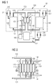
- Fig. 1 shows a possible embodiment of an uninterruptible power supply (UPS) unit 10 for subsea applications, according to the present invention.
- UPS uninterruptible power supply
- the UPS unit 10 comprises a main enclosure 150 filled with a dielectric fluid 151, e.g. Midel 7131 or another similar dielectric fluid.
- a dielectric fluid pressure compensator 230 is connected to the main enclosure 150 for providing pressure balancing between an ambient medium (e.g. sea water) surrounding the main enclosure 150 and the dielectric fluid inside the main enclosure 150.
- the pressure compensator 230 is of one of the types already known in the art, for example including a metallic bellow 231, and therefore not described in further detail.
- the UPS unit 10 includes a flow battery 100 housed in the main enclosure 150, immersed in the dielectric fluid 151.
- Flow batteries also called “redox flow batteries” or “redox flow cell”
- the rechargeability is provided by two electrolytes contained within the system and separated by a membrane.
- the flow battery 100 includes, in the embodiment of Fig. 1 , a flow battery module 101 having a negative electrode cell 110 and a positive electrode cell 120, separated by a ion selective membrane 115 (also called "proton exchange membrane").
- the ion selective membrane 115 may be made of a fluoropolymer, such as Nafion.
- the a flow battery module 101 includes a negative electrode (anode) 116 and a positive electrode (cathode) 117 at opposite ends of the flow battery module 101, in such a way that the negative electrode cell 110 is comprised between the anode 116 and the membrane 115 and that the positive electrode cell 120 is comprised between the membrane 115 and the cathode 117.
- the flow battery module 101 may be of different types, depending from the electrolytes which are used inside the electrode cells 110, 120. Possible choices are:
- the flow battery 100 includes a first electrolyte storage tank 130 connected to the negative electrode cell 110 to provide the negative electrode cell 110 with a first electrolyte.
- a first supply manifold 131 is provided to connect the first electrolyte storage tank 130 to a first end of the negative electrode cell 110.
- the first supply manifold 131 delivers a flow of fresh first electrolyte from the first electrolyte storage tank 130 to the negative electrode cell 110.
- a first discharge manifold 132 is provided to connect a second end of the negative electrode cell 110 to the first electrolyte storage tank 130.
- the first discharge manifold 132 collects a flow of spent first electrolyte from the negative electrode cell 110 and delivers it back to the first electrolyte storage tank 130.
- a first electrolyte pump 170 for pumping the first electrolyte from the first electrolyte storage tank 130 to the negative electrode cell 110 is provided along the first supply manifold 131. According to another embodiment of the present invention (not shown) the first electrolyte pump 170 and the first electrolyte is fed to the negative electrode cell 110 by gravity.
- the flow battery 100 includes a second electrolyte storage tank 140 connected to the positive electrode cell 120 to provide the positive electrode cell 120 with a second electrolyte.
- a second supply manifold 141 is provided to connect the second electrolyte storage tank 140 to a first end of the positive electrode cell 120.
- the second supply manifold 141 delivers a flow of fresh first electrolyte from the second electrolyte storage tank 140 to the positive electrode cell 120.
- a second discharge manifold 142 is provided to connect a second end of the positive electrode cell 120 to the second electrolyte storage tank 140.
- the second discharge manifold 142 collects a flow of spent second electrolyte from the positive electrode cell 120 and delivers it back to the second electrolyte storage tank 140.
- a second electrolyte pump 180 for pumping the second electrolyte from the second electrolyte storage tank 130 to the positive electrode cell 120 is provided along the second supply manifold 141. According to another embodiment of the present invention (not shown) the second electrolyte pump 180 and the second electrolyte is fed to the positive electrode cell 120 by gravity.
- the flow battery 100 further comprises:
- Both the pressure compensators 210, 220 are of one of the types already known in the art, for example including respective metallic bellows 211, 221, and therefore not described in further detail.
- the UPS unit 10 comprises only one electrolyte pressure compensator connected to both the first and second electrolyte storage tanks 130, 140 for providing pressure balancing between the ambient medium (sea water) and the first and second electrolytes inside the first and second electrolyte storage tanks 130, 140.
- one electrolyte pressure compensator may be provided, which comprises two different chambers, one for compensating the pressure in the first electrolyte pressure compensator 210 and the other for compensating the pressure in the second electrolyte pressure compensator 220.
- the first and second electrolyte storage tanks 130, 140 and the first and second pressure compensator 210, 220 are outside the main enclosure 150. According to another embodiment of the present invention (not shown) the first electrolyte storage tanks 130 and the first pressure compensator 210 are housed inside the main enclosure 150.
- the second electrolyte storage tanks 140 and the second pressure compensator 220 are housed inside the main enclosure 150.
- the first and second electrolyte storage tanks 130, 140 and the first and second pressure compensator 210, 220 are all housed inside the main enclosure 150.
- the UPS unit 10 of Fig. 1 comprises, inside the main enclosure 150, an electrical power converter 190 electrically connected to the anode 116 and cathode 117 of the flow battery module 101 and electrically connectable to an external load (for example a subsea VSD) which has to be powered by the UPS unit 10.
- the electrical power converter 190 may be an AC/DC converter or another type of converter transforming the output of the flow battery module 101 into a convenient input for the external load.
- the UPS unit 10 of Fig. 1 comprises, inside the main enclosure 150, a control system module 195 for controlling the flow rate generated by the electrolyte pumps 170, 180 (for example by controlling the speed of the electrolyte pumps 170, 180) and controlling the output of the electrical power converter 190.
- Fig. 2 shows a different possible embodiment of the flow battery module for the UPS unit 10, according to the present invention.
- the flow battery module 101 has a plurality of negative electrode cells 110 (three negative electrode cells 110) and a plurality of positive electrode cell 120 (three positive electrode cells 120) arranged in series.
- Each couple of adjacent negative and positive electrode cells 110, 120 having the negative electrode cell 110 facing the anode 116 and the positive electrode cell 120 facing the cathode 117 constitutes a single elementary cell of flow battery module 101.
- the electrodes are separated by a respective ion selective membrane 115 (three selective membranes 115 are present).
- Each elementary cell 110, 120 is separated from another elementary cell 110, 120 by means of a bipolar electrode 118 (two bipolar electrodes 118) including an anode and a cathode).
- This embodiment allows multiplying the output voltage of the flow battery module 101, with respect to the output voltage (1-3 Vdc) of embodiment of Fig. 1 , with one negative electrode cell 110 and one negative electrode cell 110.
- each negative electrode cell 110 is connected to the same first supply manifold 131 and the same first discharge manifold 132.
- Each positive electrode cell 120 is connected to the same second supply manifold 141 and the same second discharge manifold 142.
- Fig. 3 shows another different possible embodiment of the flow battery module for the UPS unit 10, according to the present invention.
- the UPS unit 10 further comprises an electrolyte valve 201, 202, 203, 204 on each of the first supply manifold 131, the first discharge manifold 132, the second supply manifold 141 and the second discharge manifold 142, respectively.
- the first electrolyte valve 201 is interposed between the first electrolyte storage tank 130 and the first electrolyte pump 170.
- the second electrolyte valve 202 controls the flow of the first electrolyte from the flow battery module 101 to the first electrolyte storage tank 130.
- the third electrolyte valve 203 is interposed between the second electrolyte storage tank 140 and the second electrolyte pump 180.
- the fourth electrolyte valve 204 controls the flow of the second electrolyte from the flow battery module 101 to the second electrolyte storage tank 140.
- the electrolyte valves 201, 202, 203, 204 permits to hydraulically isolate the flow battery module 101 from the electrolyte storage tanks 130 140, in particular in case a leakage in the flow battery module 101 occurs.
- a plurality of electrical switches (two electrical switches 191, 192 in the embodiment of Fig. 3 ) is provided between the flow battery module 101 and the electrical power converter 190.
- the electrical switches 191, 192 permit to electrically isolate the flow battery module 101 from the electrical power converter 190, in particular in case an electrical failure occurs in the flow battery module 101 or in the electrical power converter 190.
- the first and the second electrolyte pumps 170, 180, the electrolyte valves 201, 202, 203, 204, electrical power converter 190, the control system module 195 and the electrical switches 191, 192 are all housed inside the main enclosure 150.
- any of the first and the second electrolyte pumps 170, 180, the electrolyte valves 201, 202, 203, 204, electrical power converter 190, the control system module 195 and the electrical switches 191, 192 may be housed outside the main enclosure 150.
- Fig. 4 shows another different possible embodiment of the flow battery module for the UPS unit 10, according to the present invention.
- the UPS unit 10 comprises a plurality of flow battery modules (in particular, three flow battery modules 101, 102, 103). Each module 101, 102, 103 is hydraulically connected to the common first electrolyte storage tank 130 and to the common second electrolyte storage tank 140 and electrically connected to the common electrical power converter 190 (not shown in Fig. 4 ).
- the flow battery modules 101, 102, 103 are, in possible embodiments of the present invention, standardized components containing a number of single elementary cell connected in series (as described with reference to Fig. 2 ). Electrolyte pumps 170, 180, electrolyte valves 201, 202, 203, 204, and electrical switches 191, 192 may be provided for each flow battery modules 101, 102, 103.
Landscapes
- Life Sciences & Earth Sciences (AREA)
- Engineering & Computer Science (AREA)
- Manufacturing & Machinery (AREA)
- Sustainable Development (AREA)
- Sustainable Energy (AREA)
- Chemical & Material Sciences (AREA)
- Chemical Kinetics & Catalysis (AREA)
- Electrochemistry (AREA)
- General Chemical & Material Sciences (AREA)
- Fuel Cell (AREA)
- Secondary Cells (AREA)
Abstract
An uninterruptible power supply unit (10) for subsea applications comprising at least a flow battery (100) includes:
- on or more flow battery modules (101, 102, 103) having at least a negative electrode cell (110) and at least a positive electrode cell (120),
- a first electrolyte storage tank (130) connected to the negative electrode cell (110) to provide the negative electrode cell (110) with a first electrolyte,
- a second electrolyte storage tank (140) connected to the positive electrode cell (120) to provide the positive electrode cell (120) with a second electrolyte,
- at least one electrolyte pressure compensator (210, 220) connected to the first electrolyte storage tank (130) and to the second electrolyte storage tank (140) for providing pressure balancing between an ambient medium surrounding the at least one electrolyte pressure compensator (210, 220) and the first and second electrolytes inside the first and second electrolyte storage tanks (130, 140).
- on or more flow battery modules (101, 102, 103) having at least a negative electrode cell (110) and at least a positive electrode cell (120),
- a first electrolyte storage tank (130) connected to the negative electrode cell (110) to provide the negative electrode cell (110) with a first electrolyte,
- a second electrolyte storage tank (140) connected to the positive electrode cell (120) to provide the positive electrode cell (120) with a second electrolyte,
- at least one electrolyte pressure compensator (210, 220) connected to the first electrolyte storage tank (130) and to the second electrolyte storage tank (140) for providing pressure balancing between an ambient medium surrounding the at least one electrolyte pressure compensator (210, 220) and the first and second electrolytes inside the first and second electrolyte storage tanks (130, 140).
Description
- The present invention relates to an uninterruptible power supply (UPS) unit for subsea applications.
- In subsea applications, subsea power grids have been developed for supplying power to devices that are located on the seabed, e.g. a compressor used to compress gas from an offshore gas field through a pipeline to an onshore destination. A subsea power grid may include, for example, a subsea transformer or a subsea switchgear or a subsea variable speed drive (VSD). Typical water depth for such subsea applications can be 3000 m (corresponding to a pressure of 300 bar) or more.
- In subsea applications of the above mentioned type, also uninterruptible power supply (UPS) may be used. In particular, if the subsea power grid is to be used to supply critical loads that require a backup power (i.e. until safe shutdown of the process is obtained) a subsea UPS system is required. Critical loads can be control systems or subsea VSDs driving a critical rotating device, e.g. a compressor. In present subsea applications, it is also known to locate batteries or UPSs inside pressure resistant chambers, assuring that a pressure of 1 atm is maintained inside the enclosure where the components are located.
- The main inconvenience of such technical solution is that a pressure chamber designed for any considerable volume, as it is required to containing the UPS components, must have extremely thick walls to withstand the pressure. This leads, as further inconveniences, to an excessively high weight, high cost of materials and difficult cooling conditions.
- It is therefore an object of the present invention to provide an uninterruptible power supply (UPS) unit for subsea applications, which overcome the inconveniences above described.
- In order to achieve the objects defined above, an uninterruptible power supply (UPS) unit according to the independent claim are provided. The dependent claims describe advantageous developments and modifications of the invention.
- According to a first aspect of the present invention, an uninterruptible power supply unit for subsea applications comprises a flow battery including:
- at least a flow battery module having at least a negative electrode cell and at least a positive electrode cell,
- a first electrolyte storage tank connected to the negative electrode cell to provide the negative electrode cell with a first electrolyte,
- a second electrolyte storage tank connected to the positive electrode cell to provide the positive electrode cell with a second electrolyte,
- The uninterruptible power supply unit comprises at least one electrolyte pressure compensator connected to the first electrolyte storage tank and to the second electrolyte storage tank for providing pressure balancing between an ambient medium surrounding the at least one electrolyte pressure compensator and the first and second electrolytes inside the first and second electrolyte storage tanks.
- According to the present invention, the use of at least one electrolyte pressure compensator avoids the use of thick pressure chambers designed for containing the UPS components and at the same time maintaining an inside pressure of 1 atm, while the pressure of the ambient medium (sea water) surrounding the UPS unit may be typically around 300 bar.
- In the subsea UPS of the present invention, a flow battery (also called "redox flow battery" or "redox flow cell") is used and pressure compensated by adding a pressure compensator to the electrolyte tanks.
- The use of a flow battery in the UPS permits to:
- leave the battery completely discharged for long periods (months/years) with no ill effects,
- fully cycle (charge/discharge) the battery many times since there are no phase transitions involving the solids of the electrodes, in particular no or little wear and tear of the electrodes occur,
- achieve no or low self-discharge since there is no chemical action outside the cells of the electrode cells,
- achieve no emission of gasses during charging or discharging of the battery.
- The above designs including the pressure compensator provides the following further advantages:
- reduced weight of the unit,
- the energy capacity of the flow battery can easily be changed by changing the volume of the electrolyte storage tanks, up to several MWh.
- According to possible exemplary embodiments of the present invention, the uninterruptible power supply unit comprises:
- a first electrolyte pressure compensator connected to the first electrolyte storage tank for providing pressure balancing between an ambient medium surrounding the first electrolyte pressure compensator and the first electrolyte inside the first electrolyte storage tank,
- a second electrolyte pressure compensator connected to the second electrolyte storage tank for providing pressure balancing between an ambient medium surrounding the second electrolyte pressure compensator and the second electrolyte inside the second electrolyte storage tank.
- According to other possible exemplary embodiments of the present invention, the uninterruptible power supply unit further comprises:
- a main enclosure filled with a dielectric fluid, the flow battery being housed in the main enclosure immersed in the dielectric fluid,
- a dielectric fluid pressure compensator for providing pressure balancing between an ambient medium surrounding the main enclosure and the dielectric fluid inside the main enclosure.
- The pressure compensation of the main enclosure allows for passive cooling. The convective flow of the dielectric fluid in the main enclosure transports heat from the flow battery cells and from the other components, which are eventually present inside the main enclosure, to the enclosure walls and finally to the ambient medium (sea water).
- According to other possible exemplary embodiments of the present invention, the main enclosure further houses:
- at least one of the first electrolyte storage tank and of the second electrolyte storage tank,
- at least one electrolyte storage tank providing pressure balancing between the dielectric fluid inside the main enclosure and electrolyte inside the electrolyte storage tank which is housed in the main enclosure.
- Having one or both of the tanks inside the main enclosure provides an overall compact design of the UPS.
- According to respective embodiments of the present inventions, the uninterruptible power supply unit further comprises one or more of the following components:
- one or two electrolyte pumps for pumping one or both of the first and second electrolytes from the respective first or second electrolyte storage tank to the respective negative or positive electrode cell,
- one or more electrolyte valves interposed between the first or second electrolyte storage tank and the respective negative or positive electrode cell, respectively,
- an electrical power converter electrically connected to the flow battery modules and electrically connectable to an external load to be powered by the uninterruptible power supply unit,
- one or more electrical switches provided between the flow battery modules and the electrical power converter,
- a control system module for controlling the electrolyte pumps and the electrical power converter.
- According to the possible different embodiments of the present invention, the above components may be provided inside or outside the main enclosure.
- Electrical switches electrical connected to the anode and cathode of each flow battery module permits to electrically disconnect each flow battery module from the power converter, e.g. during or after an electrical fault, thus providing advantageous redundancy to the unit.
- The use of electrolyte valves interposed between the first or second electrolyte storage tank and the respective negative or positive electrode cell, respectively, give the advantageous possibility to disconnect each flow battery module from the electrolyte tanks, in particular in case of leakages.
- According to possible embodiments of the present invention, the flow battery module has a plurality of negative electrode cell and a plurality of positive electrode cell arranged in series. Advantageously, this allows providing a higher output voltage, which makes the fuel cell and converting process more efficient.
- According to other possible embodiments of the present invention, the flow battery includes a plurality of flow battery modules, each modules being connected to the first electrolyte storage tank and to the second electrolyte storage tank.
- Advantageously, this allows the power capacity can be increased by adding more fuel cell modules in parallel, up to several MW, because the power a flow battery can supply is a function of the surface area of the electrodes and membranes. This also means that the power capacity is decoupled from the energy storage. In a flow battery the energy is stored chemically in the electrolytes, and therefore it can be changed by changing the volume of the electrolyte storage tanks.
- According to a possible embodiment of the present invention, the first and/or the second electrolyte is Vanadium.
The Vanadium redox battery has a very fast response to changing loads (i.e. 100% change in 0,5 ms) and very large overload capabilities (i.e. 400% for 10 sec). As an alternative Zinc Bromine flow batteries or Polysulphide flow batteries may be used. As a further alternative, flow batteries having organic solutions as electrolytes may be used. Organic electrolytes are expected to be less toxic, have higher energy storage capabilities per volume, and lower cost of the electrolyte. - The aspects defined above and further aspects of the present invention are apparent from the examples of embodiment to be described hereinafter and are explained with reference to the examples of embodiment. The invention will be described in more detail hereinafter with reference to examples of embodiment but to which the invention is not limited.
-
-
Fig. 1 shows a schematic view of an uninterruptible power supply unit for subsea application, according to the present invention, -
Fig. 2 shows a schematic partial view of a first alternative embodiment of an uninterruptible power supply unit for subsea application, according to the present invention, -
Fig. 3 shows a schematic partial view of a second alternative embodiment of an uninterruptible power supply unit for subsea application, according to the present invention, -
Fig. 4 shows a schematic partial view of a third alternative embodiment of an uninterruptible power supply unit for subsea application, according to the present invention. - The illustrations in the drawings are schematic. It is noted that in different figures, similar or identical elements are provided with the same reference signs.
-
Fig. 1 shows a possible embodiment of an uninterruptible power supply (UPS)unit 10 for subsea applications, according to the present invention. - The
UPS unit 10 comprises amain enclosure 150 filled with adielectric fluid 151, e.g. Midel 7131 or another similar dielectric fluid. A dielectricfluid pressure compensator 230 is connected to themain enclosure 150 for providing pressure balancing between an ambient medium (e.g. sea water) surrounding themain enclosure 150 and the dielectric fluid inside themain enclosure 150. Thepressure compensator 230 is of one of the types already known in the art, for example including ametallic bellow 231, and therefore not described in further detail. - The
UPS unit 10 includes aflow battery 100 housed in themain enclosure 150, immersed in thedielectric fluid 151. Flow batteries (also called "redox flow batteries" or "redox flow cell") are a subclass of regenerative fuel cells. The rechargeability is provided by two electrolytes contained within the system and separated by a membrane. - The
flow battery 100 includes, in the embodiment ofFig. 1 , aflow battery module 101 having anegative electrode cell 110 and apositive electrode cell 120, separated by a ion selective membrane 115 (also called "proton exchange membrane"). The ionselective membrane 115 may be made of a fluoropolymer, such as Nafion. - The a
flow battery module 101 includes a negative electrode (anode) 116 and a positive electrode (cathode) 117 at opposite ends of theflow battery module 101, in such a way that thenegative electrode cell 110 is comprised between theanode 116 and themembrane 115 and that thepositive electrode cell 120 is comprised between themembrane 115 and thecathode 117. - The
flow battery module 101 may be of different types, depending from the electrolytes which are used inside theelectrode cells - Vanadium,
- Zinc Bromine,
- Polysulphide Bromine,
- organic electrolytes, where metal ions are replaced with organic charge carriers such as quinones.
- other electrolytes.
- The
flow battery 100 includes a firstelectrolyte storage tank 130 connected to thenegative electrode cell 110 to provide thenegative electrode cell 110 with a first electrolyte. Afirst supply manifold 131 is provided to connect the firstelectrolyte storage tank 130 to a first end of thenegative electrode cell 110. Thefirst supply manifold 131 delivers a flow of fresh first electrolyte from the firstelectrolyte storage tank 130 to thenegative electrode cell 110. Afirst discharge manifold 132 is provided to connect a second end of thenegative electrode cell 110 to the firstelectrolyte storage tank 130. Thefirst discharge manifold 132 collects a flow of spent first electrolyte from thenegative electrode cell 110 and delivers it back to the firstelectrolyte storage tank 130. Afirst electrolyte pump 170 for pumping the first electrolyte from the firstelectrolyte storage tank 130 to thenegative electrode cell 110 is provided along thefirst supply manifold 131. According to another embodiment of the present invention (not shown) thefirst electrolyte pump 170 and the first electrolyte is fed to thenegative electrode cell 110 by gravity. - The
flow battery 100 includes a secondelectrolyte storage tank 140 connected to thepositive electrode cell 120 to provide thepositive electrode cell 120 with a second electrolyte. Asecond supply manifold 141 is provided to connect the secondelectrolyte storage tank 140 to a first end of thepositive electrode cell 120. Thesecond supply manifold 141 delivers a flow of fresh first electrolyte from the secondelectrolyte storage tank 140 to thepositive electrode cell 120. Asecond discharge manifold 142 is provided to connect a second end of thepositive electrode cell 120 to the secondelectrolyte storage tank 140. Thesecond discharge manifold 142 collects a flow of spent second electrolyte from thepositive electrode cell 120 and delivers it back to the secondelectrolyte storage tank 140. Asecond electrolyte pump 180 for pumping the second electrolyte from the secondelectrolyte storage tank 130 to thepositive electrode cell 120 is provided along thesecond supply manifold 141. According to another embodiment of the present invention (not shown) thesecond electrolyte pump 180 and the second electrolyte is fed to thepositive electrode cell 120 by gravity. - The
flow battery 100 further comprises: - a first
electrolyte pressure compensator 210 connected to the firstelectrolyte storage tank 130 for providing pressure balancing between the ambient medium (sea water) surrounding the firstelectrolyte pressure compensator 210 and the first electrolyte inside the firstelectrolyte storage tank 130, - a second
electrolyte pressure compensator 220 connected to the secondelectrolyte storage tank 140 for providing pressure balancing between the ambient medium (sea water) surrounding the secondelectrolyte pressure compensator 220 and the second electrolyte inside the secondelectrolyte storage tank 130. - Both the
pressure compensators metallic bellows 211, 221, and therefore not described in further detail. - According to another embodiment of the present invention (not shown) the
UPS unit 10 comprises only one electrolyte pressure compensator connected to both the first and secondelectrolyte storage tanks electrolyte storage tanks electrolyte pressure compensator 210 and the other for compensating the pressure in the secondelectrolyte pressure compensator 220. - In the embodiment of
Fig. 1 , the first and secondelectrolyte storage tanks second pressure compensator main enclosure 150. According to another embodiment of the present invention (not shown) the firstelectrolyte storage tanks 130 and thefirst pressure compensator 210 are housed inside themain enclosure 150. - According to another embodiment of the present invention (not shown) the second
electrolyte storage tanks 140 and thesecond pressure compensator 220 are housed inside themain enclosure 150. - According to yet another embodiment of the present invention (not shown) the first and second
electrolyte storage tanks second pressure compensator main enclosure 150. - The
UPS unit 10 ofFig. 1 comprises, inside themain enclosure 150, anelectrical power converter 190 electrically connected to theanode 116 andcathode 117 of theflow battery module 101 and electrically connectable to an external load (for example a subsea VSD) which has to be powered by theUPS unit 10. Theelectrical power converter 190 may be an AC/DC converter or another type of converter transforming the output of theflow battery module 101 into a convenient input for the external load. - The
UPS unit 10 ofFig. 1 comprises, inside themain enclosure 150, acontrol system module 195 for controlling the flow rate generated by the electrolyte pumps 170, 180 (for example by controlling the speed of the electrolyte pumps 170, 180) and controlling the output of theelectrical power converter 190. -
Fig. 2 shows a different possible embodiment of the flow battery module for theUPS unit 10, according to the present invention. According to such embodiment, theflow battery module 101 has a plurality of negative electrode cells 110 (three negative electrode cells 110) and a plurality of positive electrode cell 120 (three positive electrode cells 120) arranged in series. Each couple of adjacent negative andpositive electrode cells negative electrode cell 110 facing theanode 116 and thepositive electrode cell 120 facing thecathode 117 constitutes a single elementary cell offlow battery module 101. In eachelementary cell selective membranes 115 are present). Eachelementary cell elementary cell - This embodiment allows multiplying the output voltage of the
flow battery module 101, with respect to the output voltage (1-3 Vdc) of embodiment ofFig. 1 , with onenegative electrode cell 110 and onenegative electrode cell 110. In -
Fig. 2 , eachnegative electrode cell 110 is connected to the samefirst supply manifold 131 and the samefirst discharge manifold 132. Eachpositive electrode cell 120 is connected to the samesecond supply manifold 141 and the samesecond discharge manifold 142. -
Fig. 3 shows another different possible embodiment of the flow battery module for theUPS unit 10, according to the present invention. According to such embodiment, theUPS unit 10 further comprises anelectrolyte valve first supply manifold 131, thefirst discharge manifold 132, thesecond supply manifold 141 and thesecond discharge manifold 142, respectively. - The
first electrolyte valve 201 is interposed between the firstelectrolyte storage tank 130 and thefirst electrolyte pump 170. Thesecond electrolyte valve 202 controls the flow of the first electrolyte from theflow battery module 101 to the firstelectrolyte storage tank 130. - The
third electrolyte valve 203 is interposed between the secondelectrolyte storage tank 140 and thesecond electrolyte pump 180. Thefourth electrolyte valve 204 controls the flow of the second electrolyte from theflow battery module 101 to the secondelectrolyte storage tank 140. - The
electrolyte valves flow battery module 101 from theelectrolyte storage tanks 130 140, in particular in case a leakage in theflow battery module 101 occurs. - A plurality of electrical switches (two
electrical switches Fig. 3 ) is provided between theflow battery module 101 and theelectrical power converter 190. Theelectrical switches flow battery module 101 from theelectrical power converter 190, in particular in case an electrical failure occurs in theflow battery module 101 or in theelectrical power converter 190. - In the embodiments of
Fig. 1 to 3 , the first and the second electrolyte pumps 170, 180, theelectrolyte valves electrical power converter 190, thecontrol system module 195 and theelectrical switches main enclosure 150. - According to other embodiments of the present invention (not shown) any of the first and the second electrolyte pumps 170, 180, the
electrolyte valves electrical power converter 190, thecontrol system module 195 and theelectrical switches main enclosure 150. -
Fig. 4 shows another different possible embodiment of the flow battery module for theUPS unit 10, according to the present invention. According to such embodiment, theUPS unit 10 comprises a plurality of flow battery modules (in particular, threeflow battery modules module electrolyte storage tank 130 and to the common secondelectrolyte storage tank 140 and electrically connected to the common electrical power converter 190 (not shown inFig. 4 ). - The
flow battery modules Fig. 2 ). Electrolyte pumps 170, 180,electrolyte valves electrical switches flow battery modules
Claims (14)
- An uninterruptible power supply unit (10) for subsea applications comprising a flow battery (100) including:- at least a flow battery module (101, 102, 103) having at least a negative electrode cell (110) and at least a positive electrode cell (120),- a first electrolyte storage tank (130) connected to the negative electrode cell (110) to provide the negative electrode cell (110) with a first electrolyte,- a second electrolyte storage tank (140) connected to the positive electrode cell (120) to provide the positive electrode cell (120) with a second electrolyte,wherein the uninterruptible power supply unit (10) further comprises at least one electrolyte pressure compensator (210, 220) connected to the first electrolyte storage tank (130) and to the second electrolyte storage tank (140) for providing pressure balancing between an ambient medium surrounding the at least one electrolyte pressure compensator (210, 220) and the first and second electrolytes inside the first and second electrolyte storage tanks (130, 140).
- The uninterruptible power supply unit (10) according to claim 1, wherein the uninterruptible power supply unit (10) comprises:- a first electrolyte pressure compensator (210) connected to the first electrolyte storage tank (130) for providing pressure balancing between an ambient medium surrounding the first electrolyte pressure compensator (210) and the first electrolyte inside the first electrolyte storage tank (130),- a second electrolyte pressure compensator (220) connected to the second electrolyte storage tank (140) for providing pressure balancing between an ambient medium surrounding the second electrolyte pressure compensator (220) and the second electrolyte inside the second electrolyte storage tank (130).
- The uninterruptible power supply unit (10) according to claim 1 or 2, wherein the uninterruptible power supply unit (10) further comprises:- a main enclosure (150) filled with a dielectric fluid, the flow battery (100) being housed in the main enclosure (150) immersed in the dielectric fluid,- a dielectric fluid pressure compensator (230) for providing pressure balancing between an ambient medium surrounding the main enclosure (150) and the dielectric fluid inside the main enclosure (150).
- The uninterruptible power supply unit (10) according to claim 3, wherein the main enclosure (150) further houses:- at least one of the first electrolyte storage tank (130) and of the second electrolyte storage tank (140),- at least one electrolyte storage tank (130, 140) providing pressure balancing between the dielectric fluid inside the main enclosure (150) and electrolyte inside the electrolyte storage tank (130, 140) which is housed in the main enclosure (150).
- The uninterruptible power supply unit (10) according to claim 3 or 4, wherein the uninterruptible power supply unit (10) further comprises at least an electrolyte pump (170, 180) for pumping one of the first and second electrolytes from the respective first or second electrolyte storage tank (130, 140) to the respective negative or positive electrode cell (110, 120).
- The uninterruptible power supply unit (10) according to claim 5, wherein the uninterruptible power supply unit (10) comprises:- a first electrolyte pump (170) for pumping the first electrolyte from the first electrolyte storage tank (130) to the negative electrode cell (110),- a second electrolyte pump (180) for pumping the second electrolyte from the second electrolyte storage tank (140) to the positive electrode cell (120).
- The uninterruptible power supply unit (10) according to any of the claims 5 or 6, wherein the uninterruptible power supply unit (10) further comprises at least an electrolyte valve (201, 202, 203, 204) interposed between the first or second electrolyte storage tank (130, 140) and the respective negative or positive electrode cell (110, 120), respectively.
- The uninterruptible power supply unit (10) according to any of the claims 3 to 7, wherein the uninterruptible power supply unit (10) further comprises an electrical power converter (190) electrically connected to the flow battery modules (101, 102, 103) and electrically connectable to an external load to be powered by the uninterruptible power supply unit (10).
- The uninterruptible power supply unit (10) according to claim 8, wherein one or more electrical switches (191, 192) are provided between the flow battery modules (101, 102, 103) and the electrical power converter (190).
- The uninterruptible power supply unit (10) according to any of the claims 5 to 9, wherein the uninterruptible power supply unit (10) further comprises a control system module (195) for controlling the electrolyte pumps (170, 180) and the electrical power converter (190).
- The uninterruptible power supply unit (10) according to any of the claims 3 to 9, wherein the main enclosure (150) further houses at least one of:- the first or the second electrolyte pumps (170, 180),- the electrolyte valves (201, 202, 203, 204),- electrical power converter (190),- the control system module (195).
- The uninterruptible power supply unit (10) according to any of the preceding claims, wherein the flow battery module (101, 102, 103) has a plurality of negative electrode cell (110) and a plurality of positive electrode cell (120) arranged in series.
- The uninterruptible power supply unit (10) according to any of the preceding claims, wherein the flow battery (100) includes a plurality of flow battery modules (101, 102, 103), each modules being connected to the first electrolyte storage tank (130) and to the second electrolyte storage tank (140).
- The uninterruptible power supply unit (10) according to any of the preceding claims, wherein the first and/or the second electrolyte is Vanadium.
Priority Applications (5)
| Application Number | Priority Date | Filing Date | Title |
|---|---|---|---|
| EP16170949.8A EP3249731A1 (en) | 2016-05-24 | 2016-05-24 | Subsea uninterruptible power supply |
| EP17720415.3A EP3443613B8 (en) | 2016-05-24 | 2017-04-21 | Subsea uninterruptible power supply |
| US16/303,168 US11489189B2 (en) | 2016-05-24 | 2017-04-21 | Subsea uninterruptible power supply |
| PCT/EP2017/059518 WO2017202553A1 (en) | 2016-05-24 | 2017-04-21 | Subsea uninterruptible power supply |
| AU2017271220A AU2017271220B2 (en) | 2016-05-24 | 2017-04-21 | Subsea uninterruptible power supply |
Applications Claiming Priority (1)
| Application Number | Priority Date | Filing Date | Title |
|---|---|---|---|
| EP16170949.8A EP3249731A1 (en) | 2016-05-24 | 2016-05-24 | Subsea uninterruptible power supply |
Publications (1)
| Publication Number | Publication Date |
|---|---|
| EP3249731A1 true EP3249731A1 (en) | 2017-11-29 |
Family
ID=56072262
Family Applications (2)
| Application Number | Title | Priority Date | Filing Date |
|---|---|---|---|
| EP16170949.8A Withdrawn EP3249731A1 (en) | 2016-05-24 | 2016-05-24 | Subsea uninterruptible power supply |
| EP17720415.3A Active EP3443613B8 (en) | 2016-05-24 | 2017-04-21 | Subsea uninterruptible power supply |
Family Applications After (1)
| Application Number | Title | Priority Date | Filing Date |
|---|---|---|---|
| EP17720415.3A Active EP3443613B8 (en) | 2016-05-24 | 2017-04-21 | Subsea uninterruptible power supply |
Country Status (4)
| Country | Link |
|---|---|
| US (1) | US11489189B2 (en) |
| EP (2) | EP3249731A1 (en) |
| AU (1) | AU2017271220B2 (en) |
| WO (1) | WO2017202553A1 (en) |
Cited By (3)
| Publication number | Priority date | Publication date | Assignee | Title |
|---|---|---|---|---|
| EP3561930A1 (en) * | 2018-04-26 | 2019-10-30 | Standard Energy Co., Ltd. | Redox flow battery |
| US10665882B2 (en) | 2017-03-02 | 2020-05-26 | Standard Energy Co., Ltd. | Redox flow battery |
| US12040657B2 (en) | 2020-09-18 | 2024-07-16 | Abb Schweiz Ag | Uninterruptible power supply arrangement for subsea applications |
Families Citing this family (4)
| Publication number | Priority date | Publication date | Assignee | Title |
|---|---|---|---|---|
| GB2621297B (en) * | 2021-06-04 | 2025-04-02 | Schlumberger Technology Bv | Electric blowout preventer bonnet using linear actuated roller screws |
| CN117897836A (en) * | 2021-08-31 | 2024-04-16 | Ess技术有限公司 | Systems and methods for circulating electrolyte and current in series coupled redox flow battery cells |
| US12191546B2 (en) * | 2021-09-23 | 2025-01-07 | United States Of America As Represented By The Secretary Of The Navy | Pressure-compensated flow battery for submerged use |
| NO348589B1 (en) * | 2022-06-20 | 2025-03-17 | Fmc Kongsberg Subsea As | Subsea christmas tree comprising a control and battery module and related method |
Citations (4)
| Publication number | Priority date | Publication date | Assignee | Title |
|---|---|---|---|---|
| US20030022059A1 (en) * | 2000-12-06 | 2003-01-30 | Takefumi Ito | Pressurre fluctuation prevention tank structure, electrolyte circulation type secondary battery, and redox flow type secondary battery |
| US20120291688A1 (en) * | 2010-01-19 | 2012-11-22 | John Arthur Dawes | Subsea Pressure Compensation System |
| EP2610881A1 (en) * | 2011-12-28 | 2013-07-03 | Siemens Aktiengesellschaft | Pressure compensator for a subsea device |
| US20130175041A1 (en) * | 2012-01-06 | 2013-07-11 | Schlumberger Technology Corporation | Pressure tolerant battery |
Family Cites Families (4)
| Publication number | Priority date | Publication date | Assignee | Title |
|---|---|---|---|---|
| US4092484A (en) * | 1976-09-22 | 1978-05-30 | International Telephone & Telegraph Corporation | Arrangement to prevent corona discharge and electric rupture in high voltage electrical components |
| IT1230984B (en) * | 1989-07-05 | 1991-11-08 | Giuseppe Bianchi | HIGH DENSITY ELECTRIC ACCUMULATOR FOR POINT LOADS. |
| US5876872A (en) * | 1996-11-08 | 1999-03-02 | Feezor; Michael D. | Underwater rechargeable battery and method of manufacture |
| US10333159B2 (en) * | 2014-07-07 | 2019-06-25 | Unienergy Technologies, Llc | Charge capacity management in redox flow battery string |
-
2016
- 2016-05-24 EP EP16170949.8A patent/EP3249731A1/en not_active Withdrawn
-
2017
- 2017-04-21 WO PCT/EP2017/059518 patent/WO2017202553A1/en not_active Ceased
- 2017-04-21 EP EP17720415.3A patent/EP3443613B8/en active Active
- 2017-04-21 AU AU2017271220A patent/AU2017271220B2/en active Active
- 2017-04-21 US US16/303,168 patent/US11489189B2/en active Active
Patent Citations (4)
| Publication number | Priority date | Publication date | Assignee | Title |
|---|---|---|---|---|
| US20030022059A1 (en) * | 2000-12-06 | 2003-01-30 | Takefumi Ito | Pressurre fluctuation prevention tank structure, electrolyte circulation type secondary battery, and redox flow type secondary battery |
| US20120291688A1 (en) * | 2010-01-19 | 2012-11-22 | John Arthur Dawes | Subsea Pressure Compensation System |
| EP2610881A1 (en) * | 2011-12-28 | 2013-07-03 | Siemens Aktiengesellschaft | Pressure compensator for a subsea device |
| US20130175041A1 (en) * | 2012-01-06 | 2013-07-11 | Schlumberger Technology Corporation | Pressure tolerant battery |
Cited By (3)
| Publication number | Priority date | Publication date | Assignee | Title |
|---|---|---|---|---|
| US10665882B2 (en) | 2017-03-02 | 2020-05-26 | Standard Energy Co., Ltd. | Redox flow battery |
| EP3561930A1 (en) * | 2018-04-26 | 2019-10-30 | Standard Energy Co., Ltd. | Redox flow battery |
| US12040657B2 (en) | 2020-09-18 | 2024-07-16 | Abb Schweiz Ag | Uninterruptible power supply arrangement for subsea applications |
Also Published As
| Publication number | Publication date |
|---|---|
| EP3443613B1 (en) | 2021-01-27 |
| US20200328446A1 (en) | 2020-10-15 |
| AU2017271220B2 (en) | 2020-03-26 |
| EP3443613B8 (en) | 2021-03-31 |
| AU2017271220A1 (en) | 2018-12-06 |
| WO2017202553A1 (en) | 2017-11-30 |
| US11489189B2 (en) | 2022-11-01 |
| WO2017202553A9 (en) | 2018-11-08 |
| EP3443613A1 (en) | 2019-02-20 |
Similar Documents
| Publication | Publication Date | Title |
|---|---|---|
| US11489189B2 (en) | Subsea uninterruptible power supply | |
| Price et al. | A novel approach to utility scale energy storage [regenerative fuel cells] | |
| US20100136455A1 (en) | Common Module Stack Component Design | |
| US11431010B2 (en) | Redox flow battery having electrolyte flow path independently provided therein | |
| US9853454B2 (en) | Vanadium redox battery energy storage system | |
| WO2012087454A1 (en) | Systems and methods for redox flow battery scalable modular reactant storage | |
| KR20170017013A (en) | Vanadium flow cell | |
| KR101855290B1 (en) | Redox flow battery | |
| JP2001292532A (en) | Battery energy storage system | |
| EP3602660A1 (en) | Tanks embodiment for a flow battery | |
| KR20190103565A (en) | Redox flow battery system for soc balancing among modules | |
| EP1984972B1 (en) | Reversible fuel cell | |
| US11362347B2 (en) | Advanced electrolyte mixing method for all vanadium flow batteries | |
| US5436087A (en) | Process for reducing unwanted specific electro chemical conversion in rechargeable batteries | |
| KR102178304B1 (en) | Redox flow battery using balancing flow path | |
| JP7428362B2 (en) | Energy storage system using redox flow batteries | |
| JP2021007066A (en) | Redox flow battery system | |
| KR20220096867A (en) | Redox flow battery system with DC pump | |
| CN223757514U (en) | A shared storage tank composite device for solving the problem of SOC imbalance among redundant subsystems | |
| EP4641717A1 (en) | Blackstart capable flow battery system configuration | |
| TWI880737B (en) | Liquid flow battery | |
| KR20200020688A (en) | Redox flow battery system and operating method of redox flow battery system | |
| US11309550B2 (en) | Leaks containment embodiment for electrochemical stack | |
| EP3561930B1 (en) | Redox flow battery | |
| CN117439232A (en) | Flow battery energy storage system |
Legal Events
| Date | Code | Title | Description |
|---|---|---|---|
| PUAI | Public reference made under article 153(3) epc to a published international application that has entered the european phase |
Free format text: ORIGINAL CODE: 0009012 |
|
| AK | Designated contracting states |
Kind code of ref document: A1 Designated state(s): AL AT BE BG CH CY CZ DE DK EE ES FI FR GB GR HR HU IE IS IT LI LT LU LV MC MK MT NL NO PL PT RO RS SE SI SK SM TR |
|
| AX | Request for extension of the european patent |
Extension state: BA ME |
|
| STAA | Information on the status of an ep patent application or granted ep patent |
Free format text: STATUS: THE APPLICATION IS DEEMED TO BE WITHDRAWN |
|
| 18D | Application deemed to be withdrawn |
Effective date: 20180530 |