EP3249716A1 - In-vehicle battery module - Google Patents
In-vehicle battery module Download PDFInfo
- Publication number
- EP3249716A1 EP3249716A1 EP17172045.1A EP17172045A EP3249716A1 EP 3249716 A1 EP3249716 A1 EP 3249716A1 EP 17172045 A EP17172045 A EP 17172045A EP 3249716 A1 EP3249716 A1 EP 3249716A1
- Authority
- EP
- European Patent Office
- Prior art keywords
- bus bar
- battery cells
- electrode bus
- electrode
- battery cell
- Prior art date
- Legal status (The legal status is an assumption and is not a legal conclusion. Google has not performed a legal analysis and makes no representation as to the accuracy of the status listed.)
- Granted
Links
Images


Classifications
-
- H—ELECTRICITY
- H01—ELECTRIC ELEMENTS
- H01M—PROCESSES OR MEANS, e.g. BATTERIES, FOR THE DIRECT CONVERSION OF CHEMICAL ENERGY INTO ELECTRICAL ENERGY
- H01M50/00—Constructional details or processes of manufacture of the non-active parts of electrochemical cells other than fuel cells, e.g. hybrid cells
- H01M50/30—Arrangements for facilitating escape of gases
- H01M50/342—Non-re-sealable arrangements
- H01M50/3425—Non-re-sealable arrangements in the form of rupturable membranes or weakened parts, e.g. pierced with the aid of a sharp member
-
- B—PERFORMING OPERATIONS; TRANSPORTING
- B60—VEHICLES IN GENERAL
- B60L—PROPULSION OF ELECTRICALLY-PROPELLED VEHICLES; SUPPLYING ELECTRIC POWER FOR AUXILIARY EQUIPMENT OF ELECTRICALLY-PROPELLED VEHICLES; ELECTRODYNAMIC BRAKE SYSTEMS FOR VEHICLES IN GENERAL; MAGNETIC SUSPENSION OR LEVITATION FOR VEHICLES; MONITORING OPERATING VARIABLES OF ELECTRICALLY-PROPELLED VEHICLES; ELECTRIC SAFETY DEVICES FOR ELECTRICALLY-PROPELLED VEHICLES
- B60L50/00—Electric propulsion with power supplied within the vehicle
- B60L50/50—Electric propulsion with power supplied within the vehicle using propulsion power supplied by batteries or fuel cells
- B60L50/60—Electric propulsion with power supplied within the vehicle using propulsion power supplied by batteries or fuel cells using power supplied by batteries
- B60L50/64—Constructional details of batteries specially adapted for electric vehicles
-
- H—ELECTRICITY
- H01—ELECTRIC ELEMENTS
- H01M—PROCESSES OR MEANS, e.g. BATTERIES, FOR THE DIRECT CONVERSION OF CHEMICAL ENERGY INTO ELECTRICAL ENERGY
- H01M10/00—Secondary cells; Manufacture thereof
- H01M10/60—Heating or cooling; Temperature control
- H01M10/62—Heating or cooling; Temperature control specially adapted for specific applications
- H01M10/625—Vehicles
-
- H—ELECTRICITY
- H01—ELECTRIC ELEMENTS
- H01M—PROCESSES OR MEANS, e.g. BATTERIES, FOR THE DIRECT CONVERSION OF CHEMICAL ENERGY INTO ELECTRICAL ENERGY
- H01M10/00—Secondary cells; Manufacture thereof
- H01M10/60—Heating or cooling; Temperature control
- H01M10/64—Heating or cooling; Temperature control characterised by the shape of the cells
- H01M10/643—Cylindrical cells
-
- H—ELECTRICITY
- H01—ELECTRIC ELEMENTS
- H01M—PROCESSES OR MEANS, e.g. BATTERIES, FOR THE DIRECT CONVERSION OF CHEMICAL ENERGY INTO ELECTRICAL ENERGY
- H01M50/00—Constructional details or processes of manufacture of the non-active parts of electrochemical cells other than fuel cells, e.g. hybrid cells
- H01M50/10—Primary casings, jackets or wrappings of a single cell or a single battery
- H01M50/138—Primary casings, jackets or wrappings of a single cell or a single battery adapted for specific cells, e.g. electrochemical cells operating at high temperature
-
- H—ELECTRICITY
- H01—ELECTRIC ELEMENTS
- H01M—PROCESSES OR MEANS, e.g. BATTERIES, FOR THE DIRECT CONVERSION OF CHEMICAL ENERGY INTO ELECTRICAL ENERGY
- H01M50/00—Constructional details or processes of manufacture of the non-active parts of electrochemical cells other than fuel cells, e.g. hybrid cells
- H01M50/20—Mountings; Secondary casings or frames; Racks, modules or packs; Suspension devices; Shock absorbers; Transport or carrying devices; Holders
- H01M50/204—Racks, modules or packs for multiple batteries or multiple cells
- H01M50/207—Racks, modules or packs for multiple batteries or multiple cells characterised by their shape
- H01M50/213—Racks, modules or packs for multiple batteries or multiple cells characterised by their shape adapted for cells having curved cross-section, e.g. round or elliptic
-
- H—ELECTRICITY
- H01—ELECTRIC ELEMENTS
- H01M—PROCESSES OR MEANS, e.g. BATTERIES, FOR THE DIRECT CONVERSION OF CHEMICAL ENERGY INTO ELECTRICAL ENERGY
- H01M50/00—Constructional details or processes of manufacture of the non-active parts of electrochemical cells other than fuel cells, e.g. hybrid cells
- H01M50/20—Mountings; Secondary casings or frames; Racks, modules or packs; Suspension devices; Shock absorbers; Transport or carrying devices; Holders
- H01M50/233—Mountings; Secondary casings or frames; Racks, modules or packs; Suspension devices; Shock absorbers; Transport or carrying devices; Holders characterised by physical properties of casings or racks, e.g. dimensions
- H01M50/24—Mountings; Secondary casings or frames; Racks, modules or packs; Suspension devices; Shock absorbers; Transport or carrying devices; Holders characterised by physical properties of casings or racks, e.g. dimensions adapted for protecting batteries from their environment, e.g. from corrosion
-
- H—ELECTRICITY
- H01—ELECTRIC ELEMENTS
- H01M—PROCESSES OR MEANS, e.g. BATTERIES, FOR THE DIRECT CONVERSION OF CHEMICAL ENERGY INTO ELECTRICAL ENERGY
- H01M50/00—Constructional details or processes of manufacture of the non-active parts of electrochemical cells other than fuel cells, e.g. hybrid cells
- H01M50/20—Mountings; Secondary casings or frames; Racks, modules or packs; Suspension devices; Shock absorbers; Transport or carrying devices; Holders
- H01M50/249—Mountings; Secondary casings or frames; Racks, modules or packs; Suspension devices; Shock absorbers; Transport or carrying devices; Holders specially adapted for aircraft or vehicles, e.g. cars or trains
-
- H—ELECTRICITY
- H01—ELECTRIC ELEMENTS
- H01M—PROCESSES OR MEANS, e.g. BATTERIES, FOR THE DIRECT CONVERSION OF CHEMICAL ENERGY INTO ELECTRICAL ENERGY
- H01M50/00—Constructional details or processes of manufacture of the non-active parts of electrochemical cells other than fuel cells, e.g. hybrid cells
- H01M50/30—Arrangements for facilitating escape of gases
- H01M50/308—Detachable arrangements, e.g. detachable vent plugs or plug systems
-
- H—ELECTRICITY
- H01—ELECTRIC ELEMENTS
- H01M—PROCESSES OR MEANS, e.g. BATTERIES, FOR THE DIRECT CONVERSION OF CHEMICAL ENERGY INTO ELECTRICAL ENERGY
- H01M50/00—Constructional details or processes of manufacture of the non-active parts of electrochemical cells other than fuel cells, e.g. hybrid cells
- H01M50/50—Current conducting connections for cells or batteries
- H01M50/502—Interconnectors for connecting terminals of adjacent batteries; Interconnectors for connecting cells outside a battery casing
- H01M50/507—Interconnectors for connecting terminals of adjacent batteries; Interconnectors for connecting cells outside a battery casing comprising an arrangement of two or more busbars within a container structure, e.g. busbar modules
-
- H—ELECTRICITY
- H01—ELECTRIC ELEMENTS
- H01M—PROCESSES OR MEANS, e.g. BATTERIES, FOR THE DIRECT CONVERSION OF CHEMICAL ENERGY INTO ELECTRICAL ENERGY
- H01M50/00—Constructional details or processes of manufacture of the non-active parts of electrochemical cells other than fuel cells, e.g. hybrid cells
- H01M50/50—Current conducting connections for cells or batteries
- H01M50/502—Interconnectors for connecting terminals of adjacent batteries; Interconnectors for connecting cells outside a battery casing
- H01M50/509—Interconnectors for connecting terminals of adjacent batteries; Interconnectors for connecting cells outside a battery casing characterised by the type of connection, e.g. mixed connections
- H01M50/512—Connection only in parallel
-
- H—ELECTRICITY
- H01—ELECTRIC ELEMENTS
- H01M—PROCESSES OR MEANS, e.g. BATTERIES, FOR THE DIRECT CONVERSION OF CHEMICAL ENERGY INTO ELECTRICAL ENERGY
- H01M10/00—Secondary cells; Manufacture thereof
- H01M10/04—Construction or manufacture in general
- H01M10/0422—Cells or battery with cylindrical casing
-
- H—ELECTRICITY
- H01—ELECTRIC ELEMENTS
- H01M—PROCESSES OR MEANS, e.g. BATTERIES, FOR THE DIRECT CONVERSION OF CHEMICAL ENERGY INTO ELECTRICAL ENERGY
- H01M10/00—Secondary cells; Manufacture thereof
- H01M10/04—Construction or manufacture in general
- H01M10/0486—Frames for plates or membranes
-
- H—ELECTRICITY
- H01—ELECTRIC ELEMENTS
- H01M—PROCESSES OR MEANS, e.g. BATTERIES, FOR THE DIRECT CONVERSION OF CHEMICAL ENERGY INTO ELECTRICAL ENERGY
- H01M10/00—Secondary cells; Manufacture thereof
- H01M10/42—Methods or arrangements for servicing or maintenance of secondary cells or secondary half-cells
- H01M10/52—Removing gases inside the secondary cell, e.g. by absorption
-
- H—ELECTRICITY
- H01—ELECTRIC ELEMENTS
- H01M—PROCESSES OR MEANS, e.g. BATTERIES, FOR THE DIRECT CONVERSION OF CHEMICAL ENERGY INTO ELECTRICAL ENERGY
- H01M2220/00—Batteries for particular applications
- H01M2220/20—Batteries in motive systems, e.g. vehicle, ship, plane
-
- H—ELECTRICITY
- H01—ELECTRIC ELEMENTS
- H01M—PROCESSES OR MEANS, e.g. BATTERIES, FOR THE DIRECT CONVERSION OF CHEMICAL ENERGY INTO ELECTRICAL ENERGY
- H01M50/00—Constructional details or processes of manufacture of the non-active parts of electrochemical cells other than fuel cells, e.g. hybrid cells
- H01M50/20—Mountings; Secondary casings or frames; Racks, modules or packs; Suspension devices; Shock absorbers; Transport or carrying devices; Holders
- H01M50/218—Mountings; Secondary casings or frames; Racks, modules or packs; Suspension devices; Shock absorbers; Transport or carrying devices; Holders characterised by the material
- H01M50/22—Mountings; Secondary casings or frames; Racks, modules or packs; Suspension devices; Shock absorbers; Transport or carrying devices; Holders characterised by the material of the casings or racks
- H01M50/227—Organic material
-
- H—ELECTRICITY
- H01—ELECTRIC ELEMENTS
- H01M—PROCESSES OR MEANS, e.g. BATTERIES, FOR THE DIRECT CONVERSION OF CHEMICAL ENERGY INTO ELECTRICAL ENERGY
- H01M50/00—Constructional details or processes of manufacture of the non-active parts of electrochemical cells other than fuel cells, e.g. hybrid cells
- H01M50/50—Current conducting connections for cells or batteries
- H01M50/502—Interconnectors for connecting terminals of adjacent batteries; Interconnectors for connecting cells outside a battery casing
- H01M50/509—Interconnectors for connecting terminals of adjacent batteries; Interconnectors for connecting cells outside a battery casing characterised by the type of connection, e.g. mixed connections
- H01M50/51—Connection only in series
-
- H—ELECTRICITY
- H01—ELECTRIC ELEMENTS
- H01M—PROCESSES OR MEANS, e.g. BATTERIES, FOR THE DIRECT CONVERSION OF CHEMICAL ENERGY INTO ELECTRICAL ENERGY
- H01M50/00—Constructional details or processes of manufacture of the non-active parts of electrochemical cells other than fuel cells, e.g. hybrid cells
- H01M50/50—Current conducting connections for cells or batteries
- H01M50/502—Interconnectors for connecting terminals of adjacent batteries; Interconnectors for connecting cells outside a battery casing
- H01M50/521—Interconnectors for connecting terminals of adjacent batteries; Interconnectors for connecting cells outside a battery casing characterised by the material
- H01M50/522—Inorganic material
-
- Y—GENERAL TAGGING OF NEW TECHNOLOGICAL DEVELOPMENTS; GENERAL TAGGING OF CROSS-SECTIONAL TECHNOLOGIES SPANNING OVER SEVERAL SECTIONS OF THE IPC; TECHNICAL SUBJECTS COVERED BY FORMER USPC CROSS-REFERENCE ART COLLECTIONS [XRACs] AND DIGESTS
- Y02—TECHNOLOGIES OR APPLICATIONS FOR MITIGATION OR ADAPTATION AGAINST CLIMATE CHANGE
- Y02E—REDUCTION OF GREENHOUSE GAS [GHG] EMISSIONS, RELATED TO ENERGY GENERATION, TRANSMISSION OR DISTRIBUTION
- Y02E60/00—Enabling technologies; Technologies with a potential or indirect contribution to GHG emissions mitigation
- Y02E60/10—Energy storage using batteries
-
- Y—GENERAL TAGGING OF NEW TECHNOLOGICAL DEVELOPMENTS; GENERAL TAGGING OF CROSS-SECTIONAL TECHNOLOGIES SPANNING OVER SEVERAL SECTIONS OF THE IPC; TECHNICAL SUBJECTS COVERED BY FORMER USPC CROSS-REFERENCE ART COLLECTIONS [XRACs] AND DIGESTS
- Y02—TECHNOLOGIES OR APPLICATIONS FOR MITIGATION OR ADAPTATION AGAINST CLIMATE CHANGE
- Y02P—CLIMATE CHANGE MITIGATION TECHNOLOGIES IN THE PRODUCTION OR PROCESSING OF GOODS
- Y02P70/00—Climate change mitigation technologies in the production process for final industrial or consumer products
- Y02P70/50—Manufacturing or production processes characterised by the final manufactured product
-
- Y—GENERAL TAGGING OF NEW TECHNOLOGICAL DEVELOPMENTS; GENERAL TAGGING OF CROSS-SECTIONAL TECHNOLOGIES SPANNING OVER SEVERAL SECTIONS OF THE IPC; TECHNICAL SUBJECTS COVERED BY FORMER USPC CROSS-REFERENCE ART COLLECTIONS [XRACs] AND DIGESTS
- Y02—TECHNOLOGIES OR APPLICATIONS FOR MITIGATION OR ADAPTATION AGAINST CLIMATE CHANGE
- Y02T—CLIMATE CHANGE MITIGATION TECHNOLOGIES RELATED TO TRANSPORTATION
- Y02T10/00—Road transport of goods or passengers
- Y02T10/60—Other road transportation technologies with climate change mitigation effect
- Y02T10/70—Energy storage systems for electromobility, e.g. batteries
Definitions
- the invention relates to an in-vehicle battery module that includes a plurality of cylindrical battery cells and is installed in a vehicle.
- JP 2010-113999 A discloses a battery module including a plurality of cylindrical battery cells.
- a pair of side plates are disposed on both axial sides of the cylindrical battery cells and hold the cylindrical battery cells therebetween.
- Bus bars electrically connecting the cylindrical battery cells are embedded in the side plates.
- cover members covering the side plates are disposed such that flow paths for fluid to flow through are formed between the cover members and the side plates.
- the conventional battery module disclosed in JP 2010-113999 A has the structure for holding the cylindrical battery cells.
- the conventional battery module there is no sufficient consideration about a structure for maintaining the performance of the battery module even when the members holding the cylindrical battery cells are partially damaged or degraded.
- the invention provides an in-vehicle battery module that can further improve the reliability.
- An in-vehicle battery module includes: a plurality of cylindrical battery cells each of the plurality of cylindrical battery cells including a first electrode and a second electrode at both axial ends of the cylindrical battery; a battery cell holder configured to hold the plurality of cylindrical battery cells in a state where the first electrodes and the second electrodes are exposed to outside; a protective case configured to urge end faces on first-electrode sides of the plurality of cylindrical battery cells toward second-electrode sides of the plurality of cylindrical battery cells; a vent cover provided such that the battery cell holder is positioned between the protective case and the vent cover, the vent cover and the battery cell holder disposed such that a vent space in which gas discharged from an end face on the second-electrode side of the cylindrical battery cell flows is provided between the vent cover and the battery cell holder; at least one first-electrode bus bar being in contact with the first electrodes of the plurality of cylindrical battery cells such that at least two of the cylindrical battery cells are connected in parallel to each other; at least one
- the cylindrical battery cells are held between the protective case and the second-electrode bus bar, and further, the second-electrode bus bar is supported by the support member. Therefore, even when an adhesive or the like fixing the cylindrical battery cells to the battery cell holder is damaged, the movement of the cylindrical battery cells in the axial direction is restricted, so that the electrically connected state of the cylindrical battery cells is maintained. In other words, since the performance of the battery module is maintained even when one component (adhesive) is damaged, it is possible to improve the reliability of the battery module.
- the in-vehicle battery module may include an elastic member disposed at least one of between the end faces on the first-electrode sides of the cylindrical battery cells and the protective case and between the end faces on the second-electrode sides of the cylindrical battery cells and the second-electrode bus bar such that the elastic member elastically deforms to absorb an axial height tolerance of the cylindrical battery cells.
- the cylindrical battery cells are held more reliably between the protective case and the second-electrode bus bar, so that the movement of the cylindrical battery cells in the axial direction is prevented more reliably.
- the first-electrode bus bar may be joined to the battery cell holder via the protective case, and the second-electrode bus bar may be joined to the battery cell holder via the vent cover.
- the support member may include a plurality of columnar portions disposed, at an interval, between the vent cover and the second-electrode bus bar.
- support points of the second-electrode bus bar by the columnar portions can be uniformly distributed without impairing the flow of gas, so that bending or the like of the second-electrode bus bar can be prevented more effectively.
- Insulation treatment may be applied to a surface of the vent cover, a part of the vent cover subjected to the insulation treatment may include a protruding portion that protrudes toward the second-electrode bus bar and supports the second-electrode bus bar, and the protruding portion may function as the support member.
- vent cover is used both as the support member and the vent cover, it is possible to reduce the number of components.
- the performance of a battery module is maintained even when one component (adhesive) is damaged, it is possible to improve the reliability of the battery module.
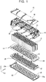
- FIG. 1 is an exploded perspective view of the battery module 10 according to the embodiment of the invention.
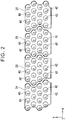
- FIG. 2 is a plan view of conductive plates 24 of a negative-electrode bus bar 25
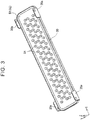
- FIG. 3 is a perspective view of a vent cover 20 that is integrated with a support member 50
- FIG. 4 is a sectional view of the battery module 10 in the YZ plane.
- a longitudinal direction of the battery module 10 will be referred to as an "X direction", an axial direction of a battery cell 12 as a "Z direction”, and a direction perpendicular to the X direction and the Z direction as a "Y direction”.
- the battery module 10 includes a plurality of cylindrical battery cells 12.
- the battery cell 12 is a chargeable and dischargeable secondary battery cell and may be, for example, a nickel-hydrogen battery cell or a lithium-ion battery cell that is housed in a cylindrical case.
- the battery cell 12 is provided at its both axial ends with a positive electrode (first electrode) and a negative electrode (second electrode) serving as electrodes of the battery cell 12.
- the battery module 10 shown in FIG. 1 includes 60 battery cells 12, and these 60 battery cells 12 are arranged in an array of 4 rows and 15 columns.
- the 60 battery cells 12 are grouped per 15 battery cells to form four battery cell groups.
- the 15 battery cells 12 belonging to the same battery cell groups are connected in parallel to each other by the negative-electrode bus bar 25 and a positive-electrode bus bar 23 which will be described later.
- the battery cell groups each including the 15 battery cells 12 connected in parallel to each other are connected in series to the other battery cell groups or external output terminals by later-described inter-group bus bars 26.
- the battery cell 12 is provided at its end face on the negative-electrode side with a discharge valve (not shown) that allows the discharge of gas generated in the battery cell 12.
- a discharge valve (not shown) that allows the discharge of gas generated in the battery cell 12.
- the discharge valve can be formed, for example, by partially thinning an exterior case of the battery cell 12. When gas is generated in the battery cell 12 due to over-charge, over-discharge, short circuit, or the like to raise the internal pressure of the battery cell 12, the discharge valve (thinned portion) is broken, so that the gas is discharged to the outside of the battery cell 12.
- the battery cells 12 are held upright with the directions of the positive electrodes and the negative electrodes aligned. In this embodiment, the battery cells 12 are held in an upright posture in which their end faces with the negative electrodes face downward (the vent cover 20 side).
- the battery cells 12 are held by a battery cell holder 14 with their lower end portions received in receiving holes 15 that are provided in the battery cell holder 14.
- the battery cell holder 14 is generally plate-shaped, and the receiving holes 15 are arranged two-dimensionally in the plate plane. In this embodiment, the receiving holes 15 are arranged in an array of 4 rows and 15 columns, and the receiving holes 15 in the adjacent rows are offset by a half pitch.
- the receiving hole 15 has a round hole shape that is fitted to the cylindrical shape of the battery cell 12.
- the battery cell 12 is inserted into the round hole 15 and fixed thereto with an adhesive 60 (see FIG. 4 ).
- the length in a central axis direction of the receiving hole 15 is set long enough to prevent the held battery cell 12 from wobbling.
- the receiving hole 15 penetrates the battery cell holder 14 in its thickness direction, so that the lower end of the battery cell 12 is exposed downward.
- the battery cell holder 14 is made of a high heat transfer material such as aluminum.
- the battery cells 12 held by the battery cell holder 14 are covered therearound with a protective case 16.
- the protective case 16 is made of an insulating resin and is generally box-shaped with its bottom portion completely open.
- the lower end of the protective case 16 is joined to the peripheral edge of the battery cell holder 14. This joining manner is not particularly limited as long as the protective case 16 can move together with the battery cell holder 14 when the battery module 10 is subjected to vibration or the like. Therefore, the protective case 16 is joined to the battery cell holder 14, for example, by fitting, screwing, or welding.
- the positive-electrode bus bar 23 (first-electrode bus bar) is integrated with the protective case 16. Therefore, it can be said that the positive-electrode bus bar 23 is joined to the battery cell holder 14 via the protective case 16.
- the protective case 16 has a ceiling plate 30 (see FIG. 4 ) that is provided near its upper end and that presses end faces on the positive-electrode sides of the battery cells 12 toward the negative-electrode sides.
- the ceiling plate 30 is provided with holding openings 32 having a diameter smaller than an outer diameter of the battery cells 12. While the positive electrodes of the battery cells 12 are exposed to the outside via the holding openings 32, the end faces of the battery cells 12 are pressed toward the negative-electrode sides by the peripheral edges of the holding openings 32.
- the positive-electrode bus bar 23 is fixed to an upper surface of the ceiling plate 30. Further, various wires (e.g. voltage detection wires and temperature detection wires) are wired above the protective case 16, and these wires are covered with an insulating cover 18.
- Inlet openings 34 (see FIG. 4 ) and outlet openings 36 (see FIG. 4 ) are formed in a peripheral surface of the protective case 16.
- the inlet openings 34 are openings for introducing into the battery module 10 cooling air that cools the battery cells 12.
- the outlet openings 36 are openings for discharging to the outside the cooling air introduced into the battery module 10.
- the outlet openings 36 are provided in a side wall of the protective case 16 on the side opposite to the inlet openings 34 such that the battery cells 12 are interposed between the inlet openings 34 and the outlet openings 36.
- the inlet openings 34 and the outlet openings 36 are slit holes provided in the side walls of the protective case 16. These slit holes are each elongated in the height direction (Z direction) and are arranged at intervals in the longitudinal direction (X direction).
- the vent cover 20 is disposed below the battery cell holder 14.
- the vent cover 20 has a generally boat shape with its peripheral edge raised upward.
- the peripheral edge of the vent cover 20 adheres to the peripheral edge of the battery cell holder 14 via the peripheral edge of the later-described support member 50, thereby forming a sealed space between the vent cover 20 and the battery cell holder 14.
- This sealed space serves as a space for disposing the later-described negative-electrode bus bar 25 (second-electrode bus bar) and also serves as a vent space 28 in which gas discharged from the battery cells 12 flows.
- the gas discharged from the battery cells 12 into the vent space 28 is discharged to the outside of the battery module 10 via exhaust holes 62 formed at end portions of the negative-electrode bus bar 25 and exhaust passages 64 (see FIG. 1 ) formed at end portions of the battery cell holder 14, and then is led to a proper position via ducts or the like.
- the vent cover 20 is also joined to the battery cell holder 14.
- This joining manner is also not particularly limited as long as the vent cover 20 can move together with the battery cell holder 14 when the battery module 10 is subjected to vibration or the like.
- the vent cover 20 has joining portions 20a extending from the peripheral edge of the vent cover 20 toward the battery cell holder 14.
- the vent cover 20 is screwed to the battery cell holder 14 via joining holes provided to the joining portions 20a.
- the vent cover 20 may be joined to the battery cell holder 14 by another joining means such as fitting or welding. Since the peripheral edge of the negative-electrode bus bar 25 is sandwiched between the vent cover 20 and the battery cell holder 14, it can be said that the negative-electrode bus bar 25 is joined to the battery cell holder 14 via the vent cover 20.
- the positive-electrode bus bar 23 electrically connecting the positive electrodes of the battery cells 12 to each other and the negative-electrode bus bar 25 electrically connecting the negative electrodes of the battery cells 12 to each other are disposed on both axial sides of the battery cells 12.
- the configurations of the positive-electrode bus bar 23 and the negative-electrode bus bar 25 are substantially the same. Therefore, hereinbelow, the configuration of the negative-electrode bus bar 25 will be mainly described with reference to FIG. 2 .
- the conductive plates 24 of the same number as that of the battery cell groups (four in this embodiment) are integrated with each other by a resin material 43, thereby forming the negative-electrode bus bar 25.
- the four conductive plates 24 are integrated with each other by the resin 43 (see FIG. 4 ) in a state where the conductive plates 24 are spaced apart from each other to maintain the insulation therebetween.
- the negative-electrode bus bar 25 is held with its peripheral edge sandwiched between the vent cover 20 and the battery cell holder 14.
- Each conductive plate 24 electrically connects to each other the negative electrodes of the 15 battery cells 12 forming the single battery cell group.
- the conductive plate 24 is a flat plate member made of a conductive material such as copper.
- the conductive plate 24 is provided with through-openings 40 corresponding to the arranged battery cells 12.
- the through-openings 40 are provided in one-to-one correspondence with the individual battery cells 12 such that the lower end faces of the corresponding battery cells 12 are exposed to the vent space 28.
- the through-opening 40 has a diameter slightly smaller than the outer diameter of the battery cell 12.
- the discharge valve provided to the battery cell 12 is exposed to the vent space 28 via the through-opening 40. Gas discharged from the battery cell 12 passes through the through-opening 40 to reach the vent space 28.
- the end face on the negative-electrode side of the battery cell 12 is supported by the peripheral edge (more precisely, the resin 43 covering the peripheral edge) of the through-opening 40.
- the battery cells 12 are held in the axial direction between the ceiling plate 30 of the protective case 16 and the negative-electrode bus bar 25.
- an elastic member 68 is disposed between the end faces on the negative-electrode sides of the battery cells 12 and the negative-electrode bus bar 25 in this embodiment.
- the elastic member 68 has a suitable elasticity and is deformed as appropriate to absorb variation in the axial height of the battery cells 12.
- the elastic member 68 is disposed on the negative-electrode sides of the battery cells 12 in this embodiment, but may be disposed on the positive-electrode sides of the battery cells 12, i.e. between the end faces on the positive-electrode sides of the battery cells 12 and the ceiling plate 30. When the tolerance in the axial direction of the battery cells 12 is small, the elastic member 68 may be omitted.
- a connecting piece 42 being a part of the conductive plate 24 is located in the through-opening 40.
- the connecting piece 42 is in the form of a plate spring having a suitable elasticity and is inclined to approach the negative electrode of the battery cell 12 as it approaches its tip.
- the tips of all the connecting pieces 42 are in contact with the negative electrodes of the corresponding battery cells 12, thereby electrically connecting the negative electrodes of the 15 battery cells 12 to each other.
- the positive-electrode bus bar 23 including conductive plates of the same shapes as the conductive plates 24 is disposed above the battery cells 12. While the negative-electrode bus bar 25 by itself forms one component, the positive-electrode bus bar 23 is assembled into the protective case 16 and integrated with the protective case 16. Each conductive plate of the positive-electrode bus bar 23 electrically connects to each other the positive electrodes of the 15 battery cells 12 forming the single battery cell group. By the negative-electrode bus bar 25 and the positive-electrode bus bar 23, the 15 battery cells 12 forming each of the battery cell groups are connected in parallel to each other.
- the four battery cell groups are connected in series to each other by the inter-group bus bars 26.
- the inter-group bus bar 26 establishes electrical connection between the conductive plate, connected to one of the battery cell groups, of the positive-electrode bus bar 23 and the conductive plate 24, connected to the adjacent other battery cell group, of the negative-electrode bus bar 25.
- the inter-group bus bar 26 is a generally flat plate member made of a conductive material such as copper and, as shown in FIGS. 1 and 4 , is disposed outside the protective case 16.
- the inter-group bus bar 26 has a generally parallelogram shape that goes in the X direction as it goes in the Z direction such that an upper end of the inter-group bus bar 26 is connected to the conductive plate, for one of the battery cell groups, of the positive-electrode bus bar 23, while its lower end is connected to the conductive plate 24, for the adjacent battery cell group, of the negative-electrode bus bar 25.
- the support member 50 is provided between the negative-electrode bus bar 25 and the vent cover 20, i.e. in the vent space 28.
- the support member 50 is made of an insulating material such as a resin.
- the support member 50 is integrated with the vent cover 20 by a resin.
- the support member 50 has a base portion 52 that adheres to an inner surface of the vent cover 20, and a plurality of columnar portions 54 standing upright from the base portion 52.
- the height of the columnar portion 54 is substantially equal to a distance from a surface of the base portion 52 to the negative-electrode bus bar 25.
- the columnar portions 54 can be interposed between the negative-electrode bus bar 25 and the vent cover 20 to support the negative-electrode bus bar 25 from the lower side (the vent cover 20 side). In order not to impede the discharge of gas, the columnar portions 54 are provided at intervals. In other words, the support member 50 is provided only partially in the vent space 28.
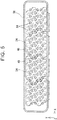
- FIG. 5 is a top view of the support member 50 of this embodiment.
- the conductive plates 24 of the negative-electrode bus bar 25 are each provided with the through-openings 40 at positions corresponding to the battery cells 12, and as is clear from FIG. 5 , in this embodiment, at least one columnar portion 54 is provided between the adjacent two through-openings 40.
- the reason for providing the support member 50 in this embodiment will be described.
- the negative-electrode bus bar 25 supporting the battery cells 12 is supported only at its peripheral edge by the peripheral edge of the vent cover 20.
- the adhesive 60 fixing the battery cells 12 to the receiving holes 15 of the battery cell holder 14 functions properly.
- the adhesive 60 fixing the battery cells 12 is mechanically degraded due to vibration during travel of a vehicle or chemically degraded due to aging, there is a possibility that the battery cells 12 come off the receiving holes 15.
- the load of the battery cells 12 is applied to the negative-electrode bus bar 25.
- the support member 50 supporting the negative-electrode bus bar 25 from the lower side is provided in the vent space 28.
- the support member 50 By providing the support member 50, even when the adhesive 60 is damaged to cause the battery cells 12 to come off the receiving holes 15, the fall of the battery cells 12 can be prevented. That is, even when the battery cells 12 come off the receiving holes 15 to apply the load thereof to the negative-electrode bus bar 25, the negative-electrode bus bar 25 is supported by the support member 50. Therefore, bending or the like of the negative-electrode bus bar 25 is effectively prevented.
- the negative-electrode bus bar 25 is supported by the support member 50, while the support member 50 is supported by the vent cover 20.
- the vent cover 20 is joined to the battery cell holder 14 as described above.
- the protective case 16 integrated with the positive-electrode bus bar 23 is also joined to the battery cell holder 14. Therefore, when the battery module 10 is subjected to vibration, the negative-electrode bus bar 25 and the protective case 16 (the positive-electrode bus bar 23) can move together with the battery cell holder 14. As a result, when the battery module 10 is subjected to vibration, the negative-electrode bus bar 25 and the positive-electrode bus bar 23 move in the same phase.
- the support member 50 is integrated with the vent cover 20 by the resin material. Therefore, it is possible to reduce the number of components of the battery module 10 and thus to reduce the number of assembly steps of the battery module 10.
- the support member 50 may be integrated with the negative-electrode bus bar 25, not with the vent cover 20, by the resin material.
- the negative-electrode bus bar 25 is supported by the columnar portions 54 arranged at intervals. With this configuration, compared to a case where the negative-electrode bus bar 25 is supported by linear ribs or the like, the vent flow is less hindered and further it is easy to uniformly distribute support points of the negative-electrode bus bar 25. As a result, bending of the negative-electrode bus bar 25 is effectively prevented, so that the movement of the battery cells 12 in the axial direction is effectively prevented.
- FIG. 6 is a sectional view in the YZ plane of a battery module 10
- FIG. 7 is a schematic plan view of a vent cover 20.
- sand-hatched portions each indicate a contact portion between a protruding portion 58 and a negative-electrode bus bar 25.
- portions of the vent cover 20 are used as support members instead of the support member 50 having the columnar portions 54. That is, the vent cover 20 of this embodiment is provided at portions of its bottom surface with the protruding portions 58 protruding to the negative-electrode bus bar 25 side and supporting the negative-electrode bus bar 25 from the lower side.
- the protruding portion 58 has a bead shape protruding in an arc and is formed, for example, by pressing a metal plate constituting the vent cover 20.
- the vent cover 20 is contiguous with the negative-electrode bus bar 25.
- insulation treatment is applied to a surface of the vent cover 20. While the manner of the insulation treatment is not particularly limited, it is possible to employ, for example, a treatment method for cation painting of insulating paint.
- the protruding portion 58 is disposed between two through-openings 40 adjacent to each other in the Y direction and has a generally linear shape extending in the X direction.
- the reason for shaping the protruding portion 58 so as to extend in the X direction is that gas from battery cells 12 is discharged to the outside from X-direction end portions of the battery module 10. That is, in the battery module 10 of this embodiment, gas discharged into a vent space 28 is discharged to the outside via exhaust holes 62 provided at X-direction end portions of the negative-electrode bus bar 25 and exhaust passages 64 provided at X-direction end portions of a battery cell holder 14.
- the protruding portion 58 is formed into the linear shape extending in the X direction. Consequently, while properly supporting peripheral portions of the through-openings 40 of the negative-electrode bus bar 25, proper venting is made possible.
- the support member 50 as a separate member from the vent cover 20 is eliminated, and the portions (the protruding portions 58) of the vent cover 20 are used as the support members.
- the portions (the protruding portions 58) of the vent cover 20 are used as the support members.
- the configurations described above are only by way of example. As long as the support member 50 supporting the bus bar is provided in the configuration in which the battery cells 12 are held between part of the protective case 16 and part of the bus bar, the other configurations may be changed as appropriate.
- the battery module 10 of each of the first and second embodiments is disposed such that the axial direction of the battery cells 12 is substantially parallel to the vertical direction.
- the disposition posture of the battery module 10 may be changed as appropriate, and, for example, the battery module 10 may be disposed such that the axial direction of the battery cells 12 is substantially parallel to the horizontal direction.
- the battery cells 12 are disposed in the posture in which the positive electrodes are located on the ceiling plate 30 (the protective case 16) side and the negative electrodes are located on the vent cover 20 side, but this may be reversed. That is, in the example of FIG. 1 , the battery cells 12 may be disposed in a posture in which the positive electrodes face downward, while the negative electrodes face upward.
- the positive-electrode bus bar 23 is preferably integrated with the protective case 16, but may be separated from the protective case 16. When the positive-electrode bus bar 23 is separated from the protective case 16, it is desirable that the positive-electrode bus bar 23 be joined to the protective case 16 by some means so as to move in the same phase with the protective case 16. Further, the numbers of the battery cells 12 and the battery cell groups forming the battery module 10 may be changed as appropriate.
Abstract
Description
- The invention relates to an in-vehicle battery module that includes a plurality of cylindrical battery cells and is installed in a vehicle.
- Conventionally, there is known a battery module that includes a plurality of cylindrical battery cells and is installed in a vehicle. For example, Japanese Patent Application Publication No.
2010-113999 JP 2010-113999 A JP 2010-113999 A - As described above, the conventional battery module disclosed in
JP 2010-113999 A - For example, in the battery module of
JP 2010-113999 A - Therefore, the invention provides an in-vehicle battery module that can further improve the reliability.
- An in-vehicle battery module according to the invention includes: a plurality of cylindrical battery cells each of the plurality of cylindrical battery cells including a first electrode and a second electrode at both axial ends of the cylindrical battery; a battery cell holder configured to hold the plurality of cylindrical battery cells in a state where the first electrodes and the second electrodes are exposed to outside; a protective case configured to urge end faces on first-electrode sides of the plurality of cylindrical battery cells toward second-electrode sides of the plurality of cylindrical battery cells; a vent cover provided such that the battery cell holder is positioned between the protective case and the vent cover, the vent cover and the battery cell holder disposed such that a vent space in which gas discharged from an end face on the second-electrode side of the cylindrical battery cell flows is provided between the vent cover and the battery cell holder; at least one first-electrode bus bar being in contact with the first electrodes of the plurality of cylindrical battery cells such that at least two of the cylindrical battery cells are connected in parallel to each other; at least one second-electrode bus bar provided in the vent space and the at least one second-electrode bus bar being in contact with the second electrodes of the plurality of cylindrical battery cells such that at least two of the cylindrical battery cells are connected in parallel to each other; and a support member disposed partially in the vent space and the support member being configured to support the second-electrode bus bar from the vent cover side.
- In this case, the cylindrical battery cells are held between the protective case and the second-electrode bus bar, and further, the second-electrode bus bar is supported by the support member. Therefore, even when an adhesive or the like fixing the cylindrical battery cells to the battery cell holder is damaged, the movement of the cylindrical battery cells in the axial direction is restricted, so that the electrically connected state of the cylindrical battery cells is maintained. In other words, since the performance of the battery module is maintained even when one component (adhesive) is damaged, it is possible to improve the reliability of the battery module.
- The in-vehicle battery module may include an elastic member disposed at least one of between the end faces on the first-electrode sides of the cylindrical battery cells and the protective case and between the end faces on the second-electrode sides of the cylindrical battery cells and the second-electrode bus bar such that the elastic member elastically deforms to absorb an axial height tolerance of the cylindrical battery cells.
- In this case, since the axial height tolerance of the cylindrical battery cells is absorbed, the cylindrical battery cells are held more reliably between the protective case and the second-electrode bus bar, so that the movement of the cylindrical battery cells in the axial direction is prevented more reliably.
- The first-electrode bus bar may be joined to the battery cell holder via the protective case, and the second-electrode bus bar may be joined to the battery cell holder via the vent cover.
- In this case, since the first-electrode bus bar and the second-electrode bus bar move in the same phase, the load applied to conducting portions of the bus bars to the cylindrical battery cells during vibration can be reduced.
- The support member may include a plurality of columnar portions disposed, at an interval, between the vent cover and the second-electrode bus bar.
- In this case, support points of the second-electrode bus bar by the columnar portions can be uniformly distributed without impairing the flow of gas, so that bending or the like of the second-electrode bus bar can be prevented more effectively.
- Insulation treatment may be applied to a surface of the vent cover, a part of the vent cover subjected to the insulation treatment may include a protruding portion that protrudes toward the second-electrode bus bar and supports the second-electrode bus bar, and the protruding portion may function as the support member.
- In this case, since the vent cover is used both as the support member and the vent cover, it is possible to reduce the number of components.
- As described above, according to the invention, since the performance of a battery module is maintained even when one component (adhesive) is damaged, it is possible to improve the reliability of the battery module.
- Features, advantages, and technical and industrial significance of exemplary embodiments of the invention will be described below with reference to the accompanying drawings, in which like numerals denote like elements, and wherein:
-
FIG. 1 is an exploded perspective view of a battery module according to an embodiment of the invention; -
FIG. 2 is a plan view of conductive plates of a negative-electrode bus bar; -
FIG. 3 is a perspective view of a vent cover integrated with a support member; -
FIG. 4 is a sectional view of the battery module in the YZ plane; -
FIG. 5 is a schematic plan view of the support member; -
FIG. 6 is a sectional view in the YZ plane of a battery module according to a second embodiment of the invention; and -
FIG. 7 is a schematic plan view of a support member of the battery module of the second embodiment. - Hereinbelow, a
battery module 10 according to an embodiment of the invention will be described with reference to the drawings.FIG. 1 is an exploded perspective view of thebattery module 10 according to the embodiment of the invention.FIG. 2 is a plan view ofconductive plates 24 of a negative-electrode bus bar 25,FIG. 3 is a perspective view of avent cover 20 that is integrated with asupport member 50, andFIG. 4 is a sectional view of thebattery module 10 in the YZ plane. In the following description, a longitudinal direction of thebattery module 10 will be referred to as an "X direction", an axial direction of abattery cell 12 as a "Z direction", and a direction perpendicular to the X direction and the Z direction as a "Y direction". - The
battery module 10 includes a plurality ofcylindrical battery cells 12. Thebattery cell 12 is a chargeable and dischargeable secondary battery cell and may be, for example, a nickel-hydrogen battery cell or a lithium-ion battery cell that is housed in a cylindrical case. Thebattery cell 12 is provided at its both axial ends with a positive electrode (first electrode) and a negative electrode (second electrode) serving as electrodes of thebattery cell 12. Thebattery module 10 shown inFIG. 1 includes 60battery cells 12, and these 60battery cells 12 are arranged in an array of 4 rows and 15 columns. The 60battery cells 12 are grouped per 15 battery cells to form four battery cell groups. The 15battery cells 12 belonging to the same battery cell groups are connected in parallel to each other by the negative-electrode bus bar 25 and a positive-electrode bus bar 23 which will be described later. The battery cell groups each including the 15battery cells 12 connected in parallel to each other are connected in series to the other battery cell groups or external output terminals by later-describedinter-group bus bars 26. - The
battery cell 12 is provided at its end face on the negative-electrode side with a discharge valve (not shown) that allows the discharge of gas generated in thebattery cell 12. As long as the discharge valve can be opened when the internal pressure of thebattery cell 12 is raised, its configuration is not particularly limited. The discharge valve can be formed, for example, by partially thinning an exterior case of thebattery cell 12. When gas is generated in thebattery cell 12 due to over-charge, over-discharge, short circuit, or the like to raise the internal pressure of thebattery cell 12, the discharge valve (thinned portion) is broken, so that the gas is discharged to the outside of thebattery cell 12. - The
battery cells 12 are held upright with the directions of the positive electrodes and the negative electrodes aligned. In this embodiment, thebattery cells 12 are held in an upright posture in which their end faces with the negative electrodes face downward (thevent cover 20 side). Thebattery cells 12 are held by abattery cell holder 14 with their lower end portions received in receivingholes 15 that are provided in thebattery cell holder 14. Thebattery cell holder 14 is generally plate-shaped, and the receivingholes 15 are arranged two-dimensionally in the plate plane. In this embodiment, the receivingholes 15 are arranged in an array of 4 rows and 15 columns, and the receivingholes 15 in the adjacent rows are offset by a half pitch. - The
receiving hole 15 has a round hole shape that is fitted to the cylindrical shape of thebattery cell 12. Thebattery cell 12 is inserted into theround hole 15 and fixed thereto with an adhesive 60 (seeFIG. 4 ). The length in a central axis direction of thereceiving hole 15 is set long enough to prevent the heldbattery cell 12 from wobbling. Thereceiving hole 15 penetrates thebattery cell holder 14 in its thickness direction, so that the lower end of thebattery cell 12 is exposed downward. In order to uniformly disperse the generated heat to reduce temperature variation among thebattery cells 12, thebattery cell holder 14 is made of a high heat transfer material such as aluminum. - The
battery cells 12 held by thebattery cell holder 14 are covered therearound with aprotective case 16. Theprotective case 16 is made of an insulating resin and is generally box-shaped with its bottom portion completely open. The lower end of theprotective case 16 is joined to the peripheral edge of thebattery cell holder 14. This joining manner is not particularly limited as long as theprotective case 16 can move together with thebattery cell holder 14 when thebattery module 10 is subjected to vibration or the like. Therefore, theprotective case 16 is joined to thebattery cell holder 14, for example, by fitting, screwing, or welding. As will be described later, the positive-electrode bus bar 23 (first-electrode bus bar) is integrated with theprotective case 16. Therefore, it can be said that the positive-electrode bus bar 23 is joined to thebattery cell holder 14 via theprotective case 16. - The
protective case 16 has a ceiling plate 30 (seeFIG. 4 ) that is provided near its upper end and that presses end faces on the positive-electrode sides of thebattery cells 12 toward the negative-electrode sides. Theceiling plate 30 is provided with holdingopenings 32 having a diameter smaller than an outer diameter of thebattery cells 12. While the positive electrodes of thebattery cells 12 are exposed to the outside via the holdingopenings 32, the end faces of thebattery cells 12 are pressed toward the negative-electrode sides by the peripheral edges of the holdingopenings 32. The positive-electrode bus bar 23 is fixed to an upper surface of theceiling plate 30. Further, various wires (e.g. voltage detection wires and temperature detection wires) are wired above theprotective case 16, and these wires are covered with an insulatingcover 18. - Inlet openings 34 (see
FIG. 4 ) and outlet openings 36 (seeFIG. 4 ) are formed in a peripheral surface of theprotective case 16. Theinlet openings 34 are openings for introducing into thebattery module 10 cooling air that cools thebattery cells 12. Theoutlet openings 36 are openings for discharging to the outside the cooling air introduced into thebattery module 10. Theoutlet openings 36 are provided in a side wall of theprotective case 16 on the side opposite to theinlet openings 34 such that thebattery cells 12 are interposed between theinlet openings 34 and theoutlet openings 36. Theinlet openings 34 and theoutlet openings 36 are slit holes provided in the side walls of theprotective case 16. These slit holes are each elongated in the height direction (Z direction) and are arranged at intervals in the longitudinal direction (X direction). - The
vent cover 20 is disposed below thebattery cell holder 14. Thevent cover 20 has a generally boat shape with its peripheral edge raised upward. The peripheral edge of thevent cover 20 adheres to the peripheral edge of thebattery cell holder 14 via the peripheral edge of the later-describedsupport member 50, thereby forming a sealed space between thevent cover 20 and thebattery cell holder 14. This sealed space serves as a space for disposing the later-described negative-electrode bus bar 25 (second-electrode bus bar) and also serves as avent space 28 in which gas discharged from thebattery cells 12 flows. The gas discharged from thebattery cells 12 into thevent space 28 is discharged to the outside of thebattery module 10 via exhaust holes 62 formed at end portions of the negative-electrode bus bar 25 and exhaust passages 64 (seeFIG. 1 ) formed at end portions of thebattery cell holder 14, and then is led to a proper position via ducts or the like. - Like the
protective case 16, thevent cover 20 is also joined to thebattery cell holder 14. This joining manner is also not particularly limited as long as thevent cover 20 can move together with thebattery cell holder 14 when thebattery module 10 is subjected to vibration or the like. In this embodiment, thevent cover 20 has joiningportions 20a extending from the peripheral edge of thevent cover 20 toward thebattery cell holder 14. Thevent cover 20 is screwed to thebattery cell holder 14 via joining holes provided to the joiningportions 20a. Instead of screwing, however, thevent cover 20 may be joined to thebattery cell holder 14 by another joining means such as fitting or welding. Since the peripheral edge of the negative-electrode bus bar 25 is sandwiched between thevent cover 20 and thebattery cell holder 14, it can be said that the negative-electrode bus bar 25 is joined to thebattery cell holder 14 via thevent cover 20. - The positive-
electrode bus bar 23 electrically connecting the positive electrodes of thebattery cells 12 to each other and the negative-electrode bus bar 25 electrically connecting the negative electrodes of thebattery cells 12 to each other are disposed on both axial sides of thebattery cells 12. The configurations of the positive-electrode bus bar 23 and the negative-electrode bus bar 25 are substantially the same. Therefore, hereinbelow, the configuration of the negative-electrode bus bar 25 will be mainly described with reference toFIG. 2 . - The
conductive plates 24 of the same number as that of the battery cell groups (four in this embodiment) are integrated with each other by aresin material 43, thereby forming the negative-electrode bus bar 25. The fourconductive plates 24 are integrated with each other by the resin 43 (seeFIG. 4 ) in a state where theconductive plates 24 are spaced apart from each other to maintain the insulation therebetween. The negative-electrode bus bar 25 is held with its peripheral edge sandwiched between thevent cover 20 and thebattery cell holder 14. - Each
conductive plate 24 electrically connects to each other the negative electrodes of the 15battery cells 12 forming the single battery cell group. Theconductive plate 24 is a flat plate member made of a conductive material such as copper. Theconductive plate 24 is provided with through-openings 40 corresponding to the arrangedbattery cells 12. The through-openings 40 are provided in one-to-one correspondence with theindividual battery cells 12 such that the lower end faces of thecorresponding battery cells 12 are exposed to thevent space 28. The through-opening 40 has a diameter slightly smaller than the outer diameter of thebattery cell 12. The discharge valve provided to thebattery cell 12 is exposed to thevent space 28 via the through-opening 40. Gas discharged from thebattery cell 12 passes through the through-opening 40 to reach thevent space 28. - The end face on the negative-electrode side of the
battery cell 12 is supported by the peripheral edge (more precisely, theresin 43 covering the peripheral edge) of the through-opening 40. In other words, thebattery cells 12 are held in the axial direction between theceiling plate 30 of theprotective case 16 and the negative-electrode bus bar 25. There is, however, a small tolerance for the size of thebattery cells 12. In order to absorb this tolerance to securely hold thebattery cells 12 between theceiling plate 30 and the negative-electrode bus bar 25, anelastic member 68 is disposed between the end faces on the negative-electrode sides of thebattery cells 12 and the negative-electrode bus bar 25 in this embodiment. Theelastic member 68 has a suitable elasticity and is deformed as appropriate to absorb variation in the axial height of thebattery cells 12. Theelastic member 68 is disposed on the negative-electrode sides of thebattery cells 12 in this embodiment, but may be disposed on the positive-electrode sides of thebattery cells 12, i.e. between the end faces on the positive-electrode sides of thebattery cells 12 and theceiling plate 30. When the tolerance in the axial direction of thebattery cells 12 is small, theelastic member 68 may be omitted. - A connecting
piece 42 being a part of theconductive plate 24 is located in the through-opening 40. The connectingpiece 42 is in the form of a plate spring having a suitable elasticity and is inclined to approach the negative electrode of thebattery cell 12 as it approaches its tip. The tips of all the connectingpieces 42 are in contact with the negative electrodes of thecorresponding battery cells 12, thereby electrically connecting the negative electrodes of the 15battery cells 12 to each other. - The positive-
electrode bus bar 23 including conductive plates of the same shapes as theconductive plates 24 is disposed above thebattery cells 12. While the negative-electrode bus bar 25 by itself forms one component, the positive-electrode bus bar 23 is assembled into theprotective case 16 and integrated with theprotective case 16. Each conductive plate of the positive-electrode bus bar 23 electrically connects to each other the positive electrodes of the 15battery cells 12 forming the single battery cell group. By the negative-electrode bus bar 25 and the positive-electrode bus bar 23, the 15battery cells 12 forming each of the battery cell groups are connected in parallel to each other. - The four battery cell groups are connected in series to each other by the inter-group bus bars 26. Specifically, the
inter-group bus bar 26 establishes electrical connection between the conductive plate, connected to one of the battery cell groups, of the positive-electrode bus bar 23 and theconductive plate 24, connected to the adjacent other battery cell group, of the negative-electrode bus bar 25. Theinter-group bus bar 26 is a generally flat plate member made of a conductive material such as copper and, as shown inFIGS. 1 and4 , is disposed outside theprotective case 16. Theinter-group bus bar 26 has a generally parallelogram shape that goes in the X direction as it goes in the Z direction such that an upper end of theinter-group bus bar 26 is connected to the conductive plate, for one of the battery cell groups, of the positive-electrode bus bar 23, while its lower end is connected to theconductive plate 24, for the adjacent battery cell group, of the negative-electrode bus bar 25. - The
support member 50 is provided between the negative-electrode bus bar 25 and thevent cover 20, i.e. in thevent space 28. Thesupport member 50 is made of an insulating material such as a resin. In this embodiment, thesupport member 50 is integrated with thevent cover 20 by a resin. Thesupport member 50 has abase portion 52 that adheres to an inner surface of thevent cover 20, and a plurality ofcolumnar portions 54 standing upright from thebase portion 52. The height of thecolumnar portion 54 is substantially equal to a distance from a surface of thebase portion 52 to the negative-electrode bus bar 25. Therefore, thecolumnar portions 54 can be interposed between the negative-electrode bus bar 25 and thevent cover 20 to support the negative-electrode bus bar 25 from the lower side (thevent cover 20 side). In order not to impede the discharge of gas, thecolumnar portions 54 are provided at intervals. In other words, thesupport member 50 is provided only partially in thevent space 28. - As will be described later, the
columnar portions 54 are provided for preventing the fall of thebattery cells 12. Therefore, it is desirable that at least onecolumnar portion 54 be provided near eachbattery cell 12, preferably near the peripheral edge of each through-opening 40.FIG. 5 is a top view of thesupport member 50 of this embodiment. As described above, theconductive plates 24 of the negative-electrode bus bar 25 are each provided with the through-openings 40 at positions corresponding to thebattery cells 12, and as is clear fromFIG. 5 , in this embodiment, at least onecolumnar portion 54 is provided between the adjacent two through-openings 40. - Next, the reason for providing the
support member 50 in this embodiment will be described. When thesupport member 50 is not provided, the negative-electrode bus bar 25 supporting thebattery cells 12 is supported only at its peripheral edge by the peripheral edge of thevent cover 20. There is no problem even with such a configuration when the adhesive 60 fixing thebattery cells 12 to the receiving holes 15 of thebattery cell holder 14 functions properly. However, when the adhesive 60 fixing thebattery cells 12 is mechanically degraded due to vibration during travel of a vehicle or chemically degraded due to aging, there is a possibility that thebattery cells 12 come off the receiving holes 15. Then, when thebattery cells 12 come off the receiving holes 15, the load of thebattery cells 12 is applied to the negative-electrode bus bar 25. In this case, there is a possibility that the negative-electrode bus bar 25 is bent or damaged due to the load of thebattery cells 12. Then, when the negative-electrode bus bar 25 is bent or damaged, thebattery cells 12 fall into thevent space 28, so that electrical connection to the positive-electrode bus bar 23 is lost. That is, when thesupport member 50 is not provided, there is a possibility that thebattery cells 12 do not function normally even only with damage to one member, i.e. the adhesive 60 fixing thebattery cells 12 to the receiving holes 15. - On the other hand, in this embodiment, as described above, the
support member 50 supporting the negative-electrode bus bar 25 from the lower side (the vent cover side) is provided in thevent space 28. By providing thesupport member 50, even when the adhesive 60 is damaged to cause thebattery cells 12 to come off the receiving holes 15, the fall of thebattery cells 12 can be prevented. That is, even when thebattery cells 12 come off the receiving holes 15 to apply the load thereof to the negative-electrode bus bar 25, the negative-electrode bus bar 25 is supported by thesupport member 50. Therefore, bending or the like of the negative-electrode bus bar 25 is effectively prevented. As a result, it is possible to continuously maintain the state where thebattery cells 12 are held between the negative-electrode bus bar 25 and theceiling plate 30 of theprotective case 16. By maintaining this state, it is possible to maintain the state where thebattery cells 12 are connected to the positive-electrode bus bar 23 and to the negative-electrode bus bar 25, so that the performance of thebattery module 10 can be properly maintained. In this way, according to this embodiment, since the performance of thebattery module 10 can be maintained even when a partial component (the adhesive 60) is damaged, it is possible to further improve the reliability of thebattery module 10. - The negative-
electrode bus bar 25 is supported by thesupport member 50, while thesupport member 50 is supported by thevent cover 20. Thevent cover 20 is joined to thebattery cell holder 14 as described above. Further, theprotective case 16 integrated with the positive-electrode bus bar 23 is also joined to thebattery cell holder 14. Therefore, when thebattery module 10 is subjected to vibration, the negative-electrode bus bar 25 and the protective case 16 (the positive-electrode bus bar 23) can move together with thebattery cell holder 14. As a result, when thebattery module 10 is subjected to vibration, the negative-electrode bus bar 25 and the positive-electrode bus bar 23 move in the same phase. Consequently, the load to the conducting portions (the tips of the connecting pieces 42) of the negative-electrode bus bar 25 and the positive-electrode bus bar 23 during vibration can be effectively reduced, so that it is possible to effectively prevent degradation of the positive-electrode/negative-electrode bus bars 23 and 25. - In this embodiment, the
support member 50 is integrated with thevent cover 20 by the resin material. Therefore, it is possible to reduce the number of components of thebattery module 10 and thus to reduce the number of assembly steps of thebattery module 10. Thesupport member 50 may be integrated with the negative-electrode bus bar 25, not with thevent cover 20, by the resin material. In this embodiment, the negative-electrode bus bar 25 is supported by thecolumnar portions 54 arranged at intervals. With this configuration, compared to a case where the negative-electrode bus bar 25 is supported by linear ribs or the like, the vent flow is less hindered and further it is easy to uniformly distribute support points of the negative-electrode bus bar 25. As a result, bending of the negative-electrode bus bar 25 is effectively prevented, so that the movement of thebattery cells 12 in the axial direction is effectively prevented. - Next, another embodiment will be described.
FIG. 6 is a sectional view in the YZ plane of abattery module 10, andFIG. 7 is a schematic plan view of avent cover 20. InFIG. 7 , sand-hatched portions each indicate a contact portion between a protrudingportion 58 and a negative-electrode bus bar 25. - In the
battery module 10, portions of thevent cover 20 are used as support members instead of thesupport member 50 having thecolumnar portions 54. That is, thevent cover 20 of this embodiment is provided at portions of its bottom surface with the protrudingportions 58 protruding to the negative-electrode bus bar 25 side and supporting the negative-electrode bus bar 25 from the lower side. The protrudingportion 58 has a bead shape protruding in an arc and is formed, for example, by pressing a metal plate constituting thevent cover 20. In this case, thevent cover 20 is contiguous with the negative-electrode bus bar 25. In order to reliably ensure insulation from the negative-electrode bus bar 25, insulation treatment is applied to a surface of thevent cover 20. While the manner of the insulation treatment is not particularly limited, it is possible to employ, for example, a treatment method for cation painting of insulating paint. - As shown in
FIG. 7 , the protrudingportion 58 is disposed between two through-openings 40 adjacent to each other in the Y direction and has a generally linear shape extending in the X direction. The reason for shaping the protrudingportion 58 so as to extend in the X direction is that gas frombattery cells 12 is discharged to the outside from X-direction end portions of thebattery module 10. That is, in thebattery module 10 of this embodiment, gas discharged into avent space 28 is discharged to the outside via exhaust holes 62 provided at X-direction end portions of the negative-electrode bus bar 25 andexhaust passages 64 provided at X-direction end portions of abattery cell holder 14. Therefore, it is satisfactory if the gas discharged into thevent space 28 can move to X-direction end portions of thevent space 28, and thus, even if the movement of the gas in the Y direction is limited to some extent, no serious problem arises. Therefore, in this embodiment, the protrudingportion 58 is formed into the linear shape extending in the X direction. Consequently, while properly supporting peripheral portions of the through-openings 40 of the negative-electrode bus bar 25, proper venting is made possible. - As is clear from the description given above, in this embodiment, the
support member 50 as a separate member from thevent cover 20 is eliminated, and the portions (the protruding portions 58) of thevent cover 20 are used as the support members. As a result, it is possible to further reduce the number of components of thebattery module 10 and thus to reduce the number of assembly steps and so on. Also in this embodiment, like in the first embodiment, even when an adhesive 60 fixing thebattery cells 12 is damaged or the like, it is possible to continuously hold thebattery cells 12 between the negative-electrode bus bar 25 and aceiling plate 30 of aprotective case 16, so that the movement of thebattery cells 12 in the axial direction is effectively prevented, resulting in that it is possible to continuously maintain electrical connection of thebattery cells 12. In this way, according to this embodiment, since the performance of thebattery module 10 can be maintained even when a partial component (the adhesive 60) is damaged, it is possible to further improve the reliability of thebattery module 10. - The configurations described above are only by way of example. As long as the
support member 50 supporting the bus bar is provided in the configuration in which thebattery cells 12 are held between part of theprotective case 16 and part of the bus bar, the other configurations may be changed as appropriate. For example, thebattery module 10 of each of the first and second embodiments is disposed such that the axial direction of thebattery cells 12 is substantially parallel to the vertical direction. However, the disposition posture of thebattery module 10 may be changed as appropriate, and, for example, thebattery module 10 may be disposed such that the axial direction of thebattery cells 12 is substantially parallel to the horizontal direction. Even in this case, as long as thebattery cells 12 are held between part of theprotective case 16 and part of the bus bar and further the bus bar is supported by thesupport member 50, the movement of thebattery cells 12 in the axial direction is effectively prevented, so that electrical connection of thebattery cells 12 is maintained. Further, in the description given above, thebattery cells 12 are disposed in the posture in which the positive electrodes are located on the ceiling plate 30 (the protective case 16) side and the negative electrodes are located on thevent cover 20 side, but this may be reversed. That is, in the example ofFIG. 1 , thebattery cells 12 may be disposed in a posture in which the positive electrodes face downward, while the negative electrodes face upward. The positive-electrode bus bar 23 is preferably integrated with theprotective case 16, but may be separated from theprotective case 16. When the positive-electrode bus bar 23 is separated from theprotective case 16, it is desirable that the positive-electrode bus bar 23 be joined to theprotective case 16 by some means so as to move in the same phase with theprotective case 16. Further, the numbers of thebattery cells 12 and the battery cell groups forming thebattery module 10 may be changed as appropriate.
Claims (5)
- An in-vehicle battery module comprising:a plurality of cylindrical battery cells (12), each of the plurality of cylindrical battery cells including a first electrode and a second electrode at both axial ends of the cylindrical battery;a battery cell holder (14) configured to hold the plurality of cylindrical battery cells in a state where the first electrodes and the second electrodes are exposed to outside;a protective case (16) configured to urge end faces on first-electrode sides of the plurality of cylindrical battery cells toward second-electrode sides of the plurality of cylindrical battery cells;a vent cover (20) provided such that the battery cell holder is positioned between the protective case and the vent cover, the vent cover and the battery cell holder disposed such that a vent space in which gas discharged from an end face on the second-electrode side of the cylindrical battery cell flows is provided between the vent cover and the battery cell holder;at least one first-electrode bus bar (23) being in contact with the first electrodes of the plurality of cylindrical battery cells such that at least two of the cylindrical battery cells are connected in parallel to each other;at least one second-electrode bus bar (25) provided in the vent space and the at least one second-electrode bus bar being in contact with the second electrodes of the plurality of cylindrical battery cells such that at least two of the cylindrical battery cells are connected in parallel to each other; anda support member (50) disposed partially in the vent space and the support member being configured to support the second-electrode bus bar from the vent cover side.
- The in-vehicle battery module according to claim 1, further comprising
an elastic member (68) disposed at least one of between the end faces on the first-electrode sides of the cylindrical battery cells and the protective case and between the end faces on the second-electrode sides of the cylindrical battery cells and the second-electrode bus bar such that the elastic member elastically deforms to absorb an axial height tolerance of the cylindrical battery cells. - The in-vehicle battery module according to claim 1 or 2, wherein
the first-electrode bus bar is joined to the battery cell holder via the protective case, and
the second-electrode bus bar is joined to the battery cell holder via the vent cover. - The in-vehicle battery module according to any one of claims 1 to 3, wherein
the support member includes a plurality of columnar portions (54) disposed, at an interval, between the vent cover and the second-electrode bus bar. - The in-vehicle battery module according to any one of claims 1 to 3, wherein
insulation treatment is applied to a surface of the vent cover,
a part of the vent cover subjected to the insulation treatment includes a protruding portion (58) that protrudes toward the second-electrode bus bar and supports the second-electrode bus bar, and
the protruding portion functions as the support member.
Applications Claiming Priority (1)
| Application Number | Priority Date | Filing Date | Title |
|---|---|---|---|
| JP2016103344A JP6350592B2 (en) | 2016-05-24 | 2016-05-24 | Automotive battery module |
Publications (2)
| Publication Number | Publication Date |
|---|---|
| EP3249716A1 true EP3249716A1 (en) | 2017-11-29 |
| EP3249716B1 EP3249716B1 (en) | 2020-01-08 |
Family
ID=58738980
Family Applications (1)
| Application Number | Title | Priority Date | Filing Date |
|---|---|---|---|
| EP17172045.1A Active EP3249716B1 (en) | 2016-05-24 | 2017-05-19 | In-vehicle battery module |
Country Status (7)
| Country | Link |
|---|---|
| US (1) | US10439178B2 (en) |
| EP (1) | EP3249716B1 (en) |
| JP (1) | JP6350592B2 (en) |
| CN (1) | CN107452906B (en) |
| BR (1) | BR102017010404A2 (en) |
| MY (1) | MY193829A (en) |
| RU (1) | RU2662730C1 (en) |
Cited By (6)
| Publication number | Priority date | Publication date | Assignee | Title |
|---|---|---|---|---|
| GB2560042A (en) * | 2017-02-28 | 2018-08-29 | Jaguar Land Rover Ltd | Busbar connector |
| KR20190086853A (en) * | 2018-01-15 | 2019-07-24 | 주식회사 엘지화학 | Battery Module Having Gas Discharge Structure |
| EP3525255A1 (en) * | 2018-02-07 | 2019-08-14 | Contemporary Amperex Technology Co., Limited | Battery module |
| CN112005399A (en) * | 2018-04-24 | 2020-11-27 | 三洋电机株式会社 | Battery module |
| WO2020259879A1 (en) * | 2019-06-24 | 2020-12-30 | Bayerische Motoren Werke Aktiengesellschaft | Energy storage device for a motor vehicle, motor vehicle, and production method |
| EP4175022A1 (en) * | 2021-10-28 | 2023-05-03 | Samsung SDI Co., Ltd. | Battery system and vehicle including the battery system |
Families Citing this family (22)
| Publication number | Priority date | Publication date | Assignee | Title |
|---|---|---|---|---|
| CA2921925A1 (en) * | 2016-02-25 | 2017-08-25 | Hydro-Quebec | Electric battery assembly |
| EP3514852A4 (en) * | 2017-07-19 | 2019-12-25 | LG Chem, Ltd. | Battery pack fixing device |
| US10930910B2 (en) | 2017-08-22 | 2021-02-23 | Toyota Jidosha Kabushiki Kaisha | Power storage module |
| JP6962236B2 (en) * | 2018-02-23 | 2021-11-05 | トヨタ自動車株式会社 | Power storage device |
| CN108735931B (en) * | 2018-04-08 | 2020-03-31 | 河南大学 | Lithium ion battery's equipment frame |
| JP7055687B2 (en) * | 2018-04-10 | 2022-04-18 | マレリ株式会社 | Batteries assembled |
| KR101953351B1 (en) * | 2018-08-01 | 2019-03-04 | 주식회사 이테스 | Non-welding type battery module and battery module assembly using it |
| US20200052259A1 (en) * | 2018-08-09 | 2020-02-13 | Tiveni MergeCo Inc. | Battery module with bottom plate on which positioning elements are arranged to position battery cells |
| DE102018218357A1 (en) * | 2018-10-26 | 2020-04-30 | Robert Bosch Gmbh | Battery cell system and method for manufacturing a battery system |
| CN111106277B (en) * | 2018-12-29 | 2021-05-07 | 宁德时代新能源科技股份有限公司 | Battery pack |
| US11316222B2 (en) | 2019-01-08 | 2022-04-26 | The Boeing Company | System and method for maintaining thermal control of battery cells |
| CN109786609A (en) * | 2019-01-31 | 2019-05-21 | 江苏敏安电动汽车有限公司 | A kind of battery series mould set and its assemble method, electric car |
| KR20200106694A (en) * | 2019-03-05 | 2020-09-15 | 삼성에스디아이 주식회사 | Secondary battery |
| CN113994531A (en) * | 2019-04-15 | 2022-01-28 | 罗伯特·博世有限公司 | Battery module with insulated bus bar assembly |
| KR20210070078A (en) * | 2019-12-04 | 2021-06-14 | 주식회사 엘지에너지솔루션 | Battery Module and Battery Pack |
| US20210288374A1 (en) * | 2020-03-16 | 2021-09-16 | Volvo Car Corporation | Cover for a battery module |
| SE2030079A1 (en) * | 2020-03-17 | 2021-09-18 | Anodox | Fully Encapsulated Immersion Cooling for battery modules and systems |
| DE102020112426A1 (en) * | 2020-05-07 | 2021-11-11 | Audi Aktiengesellschaft | High-voltage battery for an electrically powered vehicle |
| GB2598346A (en) * | 2020-08-27 | 2022-03-02 | Jaguar Land Rover Ltd | Battery module |
| US20220302561A1 (en) * | 2021-03-17 | 2022-09-22 | Power.Global, Pbc | Electric terminals with concentric springs |
| CN113437440B (en) * | 2021-08-27 | 2021-11-12 | 嘉兴模度新能源有限公司 | Electric connection switching structure, battery pack and manufacturing method thereof |
| DE102021123314A1 (en) | 2021-09-09 | 2023-03-09 | Dr. Ing. H.C. F. Porsche Aktiengesellschaft | electric vehicle |
Citations (6)
| Publication number | Priority date | Publication date | Assignee | Title |
|---|---|---|---|---|
| JP2010113999A (en) | 2008-11-07 | 2010-05-20 | Hitachi Ltd | Power storage module, power storage device, electric motor driving system, and vehicle |
| WO2013018151A1 (en) * | 2011-08-03 | 2013-02-07 | パナソニック株式会社 | Battery module |
| WO2015064097A1 (en) * | 2013-10-31 | 2015-05-07 | パナソニックIpマネジメント株式会社 | Battery module |
| US20150140369A1 (en) * | 2009-09-18 | 2015-05-21 | Panasonic Intellectual Property Management Co., Ltd. | Battery module |
| US20160141573A1 (en) * | 2013-03-29 | 2016-05-19 | Sanyo Electric Co., Ltd. | Battery pack |
| JP2016134232A (en) * | 2015-01-16 | 2016-07-25 | トヨタ自動車株式会社 | Battery pack |
Family Cites Families (22)
| Publication number | Priority date | Publication date | Assignee | Title |
|---|---|---|---|---|
| RU828913C (en) | 1980-01-23 | 1995-03-20 | Научно-исследовательский институт химических источников тока | Container for battery |
| IT1264692B1 (en) * | 1993-07-08 | 1996-10-04 | Getters Spa | GETTER COMBINATION SUITABLE FOR REVERSIBLE VACUUM INSULATING SHIRTS |
| JP4631118B2 (en) * | 1999-02-15 | 2011-02-16 | ソニー株式会社 | Battery device for moving body |
| JP3848565B2 (en) * | 2001-11-27 | 2006-11-22 | 松下電器産業株式会社 | Battery connection structure, battery module, and battery pack |
| WO2008086212A1 (en) | 2007-01-05 | 2008-07-17 | Johnson Controls-Saft Advanced Power Solutions Llc | Battery module |
| JP5082568B2 (en) * | 2007-04-26 | 2012-11-28 | トヨタ自動車株式会社 | Power storage device |
| CN102165625B (en) * | 2008-08-14 | 2015-11-25 | 江森自控帅福得先进能源动力系统有限责任公司 | The battery module of the Packed venting chambers of tool |
| US7961674B2 (en) * | 2009-01-27 | 2011-06-14 | Sony Corporation | Multi-tier wireless home mesh network with a secure network discovery protocol |
| JP5617200B2 (en) * | 2009-07-17 | 2014-11-05 | 日産自動車株式会社 | battery pack |
| KR101608729B1 (en) * | 2009-10-01 | 2016-04-20 | 삼성전자주식회사 | Image sensor module, method of manufacturing the same, imaging device including the image sensor module and method of manufacturing the imaging device |
| DE102010041278A1 (en) * | 2010-09-23 | 2012-03-29 | Robert Bosch Gmbh | Battery compartment and meter with a battery compartment |
| PL395382A1 (en) * | 2011-06-27 | 2013-01-07 | Impact Clean Power Technology Spólka Akcyjna | Electrical battery module thermally stabilized |
| JP5803513B2 (en) * | 2011-09-29 | 2015-11-04 | ソニー株式会社 | Battery pack, power storage system, electronic device and electric vehicle |
| JP5966780B2 (en) | 2011-09-30 | 2016-08-10 | 株式会社Gsユアサ | Battery pack |
| WO2014083600A1 (en) * | 2012-11-30 | 2014-06-05 | トヨタ自動車株式会社 | Electric storage apparatus |
| JP6006134B2 (en) * | 2013-02-08 | 2016-10-12 | トヨタ自動車株式会社 | Connecting member |
| JP6246483B2 (en) * | 2013-04-04 | 2017-12-13 | 株式会社マキタ | Battery pack for electric tools |
| JP5885718B2 (en) * | 2013-09-09 | 2016-03-15 | 豊田合成株式会社 | Busbar holding member and battery pack |
| JP2015099726A (en) * | 2013-11-20 | 2015-05-28 | トヨタ自動車株式会社 | Electric power storage module |
| JP6232299B2 (en) * | 2014-01-27 | 2017-11-15 | ダイキョーニシカワ株式会社 | Battery module |
| JP2016015253A (en) * | 2014-07-02 | 2016-01-28 | トヨタ自動車株式会社 | Power storage module |
| US9444125B2 (en) * | 2014-07-15 | 2016-09-13 | Atieva, Inc. | Battery pack with non-conductive structural support |
-
2016
- 2016-05-24 JP JP2016103344A patent/JP6350592B2/en active Active
-
2017
- 2017-05-11 MY MYPI2017701665A patent/MY193829A/en unknown
- 2017-05-18 BR BR102017010404-4A patent/BR102017010404A2/en active Search and Examination
- 2017-05-19 CN CN201710359530.9A patent/CN107452906B/en active Active
- 2017-05-19 EP EP17172045.1A patent/EP3249716B1/en active Active
- 2017-05-22 RU RU2017117586A patent/RU2662730C1/en active
- 2017-05-22 US US15/601,268 patent/US10439178B2/en active Active
Patent Citations (6)
| Publication number | Priority date | Publication date | Assignee | Title |
|---|---|---|---|---|
| JP2010113999A (en) | 2008-11-07 | 2010-05-20 | Hitachi Ltd | Power storage module, power storage device, electric motor driving system, and vehicle |
| US20150140369A1 (en) * | 2009-09-18 | 2015-05-21 | Panasonic Intellectual Property Management Co., Ltd. | Battery module |
| WO2013018151A1 (en) * | 2011-08-03 | 2013-02-07 | パナソニック株式会社 | Battery module |
| US20160141573A1 (en) * | 2013-03-29 | 2016-05-19 | Sanyo Electric Co., Ltd. | Battery pack |
| WO2015064097A1 (en) * | 2013-10-31 | 2015-05-07 | パナソニックIpマネジメント株式会社 | Battery module |
| JP2016134232A (en) * | 2015-01-16 | 2016-07-25 | トヨタ自動車株式会社 | Battery pack |
Cited By (11)
| Publication number | Priority date | Publication date | Assignee | Title |
|---|---|---|---|---|
| GB2560042A (en) * | 2017-02-28 | 2018-08-29 | Jaguar Land Rover Ltd | Busbar connector |
| GB2560042B (en) * | 2017-02-28 | 2020-03-25 | Jaguar Land Rover Ltd | Busbar connector |
| KR20190086853A (en) * | 2018-01-15 | 2019-07-24 | 주식회사 엘지화학 | Battery Module Having Gas Discharge Structure |
| EP3644403A4 (en) * | 2018-01-15 | 2021-01-13 | Lg Chem, Ltd. | Battery module having gas discharge structure |
| US11462799B2 (en) | 2018-01-15 | 2022-10-04 | Lg Energy Solution, Ltd. | Battery module having gas discharge structure |
| EP3525255A1 (en) * | 2018-02-07 | 2019-08-14 | Contemporary Amperex Technology Co., Limited | Battery module |
| US10629879B2 (en) | 2018-02-07 | 2020-04-21 | Contemporary Amperex Technology Co., Limited | Battery module |
| CN112005399A (en) * | 2018-04-24 | 2020-11-27 | 三洋电机株式会社 | Battery module |
| EP3787062A4 (en) * | 2018-04-24 | 2021-05-26 | SANYO Electric Co., Ltd. | Cell module |
| WO2020259879A1 (en) * | 2019-06-24 | 2020-12-30 | Bayerische Motoren Werke Aktiengesellschaft | Energy storage device for a motor vehicle, motor vehicle, and production method |
| EP4175022A1 (en) * | 2021-10-28 | 2023-05-03 | Samsung SDI Co., Ltd. | Battery system and vehicle including the battery system |
Also Published As
| Publication number | Publication date |
|---|---|
| MY193829A (en) | 2022-10-27 |
| RU2662730C1 (en) | 2018-07-30 |
| JP6350592B2 (en) | 2018-07-04 |
| US10439178B2 (en) | 2019-10-08 |
| CN107452906B (en) | 2020-06-23 |
| BR102017010404A2 (en) | 2017-12-12 |
| US20170346050A1 (en) | 2017-11-30 |
| JP2017212065A (en) | 2017-11-30 |
| EP3249716B1 (en) | 2020-01-08 |
| CN107452906A (en) | 2017-12-08 |
Similar Documents
| Publication | Publication Date | Title |
|---|---|---|
| EP3249716B1 (en) | In-vehicle battery module | |
| US11139529B2 (en) | Cylindrical battery cell assembly with improved space utilization and safety, and battery module comprising same | |
| CN108075074B (en) | Battery module | |
| EP2104121B1 (en) | Electric storage unit | |
| EP0727833A1 (en) | Cylindrical cell, a cell pack and a cell holder | |
| US10347885B2 (en) | Battery module | |
| US20120141852A1 (en) | Conductor Plate for a Vehicle Battery Module | |
| KR102587699B1 (en) | Battery Pack | |
| WO2015019570A1 (en) | Battery unit | |
| US11652256B2 (en) | Battery pack | |
| JP6696398B2 (en) | In-vehicle battery module | |
| JP7178593B2 (en) | battery module | |
| US20210167346A1 (en) | Battery pack | |
| US9799863B2 (en) | Fastening structure | |
| US20230238630A1 (en) | Battery pack | |
| US11837738B2 (en) | Battery pack | |
| KR101222386B1 (en) | Battery Pack | |
| US20220166113A1 (en) | Battery cell assembly having gas exhaust and heat emission function | |
| JP2019133900A (en) | Power storage device |
Legal Events
| Date | Code | Title | Description |
|---|---|---|---|
| PUAI | Public reference made under article 153(3) epc to a published international application that has entered the european phase |
Free format text: ORIGINAL CODE: 0009012 |
|
| STAA | Information on the status of an ep patent application or granted ep patent |
Free format text: STATUS: REQUEST FOR EXAMINATION WAS MADE |
|
| 17P | Request for examination filed |
Effective date: 20170619 |
|
| AK | Designated contracting states |
Kind code of ref document: A1 Designated state(s): AL AT BE BG CH CY CZ DE DK EE ES FI FR GB GR HR HU IE IS IT LI LT LU LV MC MK MT NL NO PL PT RO RS SE SI SK SM TR |
|
| AX | Request for extension of the european patent |
Extension state: BA ME |
|
| GRAP | Despatch of communication of intention to grant a patent |
Free format text: ORIGINAL CODE: EPIDOSNIGR1 |
|
| STAA | Information on the status of an ep patent application or granted ep patent |
Free format text: STATUS: GRANT OF PATENT IS INTENDED |
|
| RIC1 | Information provided on ipc code assigned before grant |
Ipc: H01M 2/10 20060101AFI20190626BHEP Ipc: H01M 2/12 20060101ALI20190626BHEP Ipc: H01M 10/52 20060101ALN20190626BHEP Ipc: H01M 2/20 20060101ALI20190626BHEP Ipc: H01M 10/04 20060101ALN20190626BHEP |
|
| INTG | Intention to grant announced |
Effective date: 20190729 |
|
| GRAS | Grant fee paid |
Free format text: ORIGINAL CODE: EPIDOSNIGR3 |
|
| GRAA | (expected) grant |
Free format text: ORIGINAL CODE: 0009210 |
|
| STAA | Information on the status of an ep patent application or granted ep patent |
Free format text: STATUS: THE PATENT HAS BEEN GRANTED |
|
| AK | Designated contracting states |
Kind code of ref document: B1 Designated state(s): AL AT BE BG CH CY CZ DE DK EE ES FI FR GB GR HR HU IE IS IT LI LT LU LV MC MK MT NL NO PL PT RO RS SE SI SK SM TR |
|
| REG | Reference to a national code |
Ref country code: GB Ref legal event code: FG4D |
|
| REG | Reference to a national code |
Ref country code: CH Ref legal event code: EP |
|
| REG | Reference to a national code |
Ref country code: DE Ref legal event code: R096 Ref document number: 602017010553 Country of ref document: DE |
|
| REG | Reference to a national code |
Ref country code: IE Ref legal event code: FG4D |
|
| REG | Reference to a national code |
Ref country code: AT Ref legal event code: REF Ref document number: 1223806 Country of ref document: AT Kind code of ref document: T Effective date: 20200215 |
|
| REG | Reference to a national code |
Ref country code: NL Ref legal event code: MP Effective date: 20200108 |
|
| REG | Reference to a national code |
Ref country code: LT Ref legal event code: MG4D |
|
| PG25 | Lapsed in a contracting state [announced via postgrant information from national office to epo] |
Ref country code: NO Free format text: LAPSE BECAUSE OF FAILURE TO SUBMIT A TRANSLATION OF THE DESCRIPTION OR TO PAY THE FEE WITHIN THE PRESCRIBED TIME-LIMIT Effective date: 20200408 Ref country code: NL Free format text: LAPSE BECAUSE OF FAILURE TO SUBMIT A TRANSLATION OF THE DESCRIPTION OR TO PAY THE FEE WITHIN THE PRESCRIBED TIME-LIMIT Effective date: 20200108 Ref country code: LT Free format text: LAPSE BECAUSE OF FAILURE TO SUBMIT A TRANSLATION OF THE DESCRIPTION OR TO PAY THE FEE WITHIN THE PRESCRIBED TIME-LIMIT Effective date: 20200108 Ref country code: PT Free format text: LAPSE BECAUSE OF FAILURE TO SUBMIT A TRANSLATION OF THE DESCRIPTION OR TO PAY THE FEE WITHIN THE PRESCRIBED TIME-LIMIT Effective date: 20200531 Ref country code: FI Free format text: LAPSE BECAUSE OF FAILURE TO SUBMIT A TRANSLATION OF THE DESCRIPTION OR TO PAY THE FEE WITHIN THE PRESCRIBED TIME-LIMIT Effective date: 20200108 Ref country code: RS Free format text: LAPSE BECAUSE OF FAILURE TO SUBMIT A TRANSLATION OF THE DESCRIPTION OR TO PAY THE FEE WITHIN THE PRESCRIBED TIME-LIMIT Effective date: 20200108 |
|
| PG25 | Lapsed in a contracting state [announced via postgrant information from national office to epo] |
Ref country code: HR Free format text: LAPSE BECAUSE OF FAILURE TO SUBMIT A TRANSLATION OF THE DESCRIPTION OR TO PAY THE FEE WITHIN THE PRESCRIBED TIME-LIMIT Effective date: 20200108 Ref country code: GR Free format text: LAPSE BECAUSE OF FAILURE TO SUBMIT A TRANSLATION OF THE DESCRIPTION OR TO PAY THE FEE WITHIN THE PRESCRIBED TIME-LIMIT Effective date: 20200409 Ref country code: SE Free format text: LAPSE BECAUSE OF FAILURE TO SUBMIT A TRANSLATION OF THE DESCRIPTION OR TO PAY THE FEE WITHIN THE PRESCRIBED TIME-LIMIT Effective date: 20200108 Ref country code: LV Free format text: LAPSE BECAUSE OF FAILURE TO SUBMIT A TRANSLATION OF THE DESCRIPTION OR TO PAY THE FEE WITHIN THE PRESCRIBED TIME-LIMIT Effective date: 20200108 Ref country code: IS Free format text: LAPSE BECAUSE OF FAILURE TO SUBMIT A TRANSLATION OF THE DESCRIPTION OR TO PAY THE FEE WITHIN THE PRESCRIBED TIME-LIMIT Effective date: 20200508 Ref country code: BG Free format text: LAPSE BECAUSE OF FAILURE TO SUBMIT A TRANSLATION OF THE DESCRIPTION OR TO PAY THE FEE WITHIN THE PRESCRIBED TIME-LIMIT Effective date: 20200408 |
|
| REG | Reference to a national code |
Ref country code: DE Ref legal event code: R097 Ref document number: 602017010553 Country of ref document: DE |
|
| PG25 | Lapsed in a contracting state [announced via postgrant information from national office to epo] |
Ref country code: CZ Free format text: LAPSE BECAUSE OF FAILURE TO SUBMIT A TRANSLATION OF THE DESCRIPTION OR TO PAY THE FEE WITHIN THE PRESCRIBED TIME-LIMIT Effective date: 20200108 Ref country code: ES Free format text: LAPSE BECAUSE OF FAILURE TO SUBMIT A TRANSLATION OF THE DESCRIPTION OR TO PAY THE FEE WITHIN THE PRESCRIBED TIME-LIMIT Effective date: 20200108 Ref country code: RO Free format text: LAPSE BECAUSE OF FAILURE TO SUBMIT A TRANSLATION OF THE DESCRIPTION OR TO PAY THE FEE WITHIN THE PRESCRIBED TIME-LIMIT Effective date: 20200108 Ref country code: EE Free format text: LAPSE BECAUSE OF FAILURE TO SUBMIT A TRANSLATION OF THE DESCRIPTION OR TO PAY THE FEE WITHIN THE PRESCRIBED TIME-LIMIT Effective date: 20200108 Ref country code: SM Free format text: LAPSE BECAUSE OF FAILURE TO SUBMIT A TRANSLATION OF THE DESCRIPTION OR TO PAY THE FEE WITHIN THE PRESCRIBED TIME-LIMIT Effective date: 20200108 Ref country code: DK Free format text: LAPSE BECAUSE OF FAILURE TO SUBMIT A TRANSLATION OF THE DESCRIPTION OR TO PAY THE FEE WITHIN THE PRESCRIBED TIME-LIMIT Effective date: 20200108 Ref country code: SK Free format text: LAPSE BECAUSE OF FAILURE TO SUBMIT A TRANSLATION OF THE DESCRIPTION OR TO PAY THE FEE WITHIN THE PRESCRIBED TIME-LIMIT Effective date: 20200108 |
|
| PLBE | No opposition filed within time limit |
Free format text: ORIGINAL CODE: 0009261 |
|
| STAA | Information on the status of an ep patent application or granted ep patent |
Free format text: STATUS: NO OPPOSITION FILED WITHIN TIME LIMIT |
|
| REG | Reference to a national code |
Ref country code: AT Ref legal event code: MK05 Ref document number: 1223806 Country of ref document: AT Kind code of ref document: T Effective date: 20200108 |
|
| REG | Reference to a national code |
Ref country code: DE Ref legal event code: R079 Ref document number: 602017010553 Country of ref document: DE Free format text: PREVIOUS MAIN CLASS: H01M0002100000 Ipc: H01M0050200000 |
|
| 26N | No opposition filed |
Effective date: 20201009 |
|
| PG25 | Lapsed in a contracting state [announced via postgrant information from national office to epo] |
Ref country code: AT Free format text: LAPSE BECAUSE OF FAILURE TO SUBMIT A TRANSLATION OF THE DESCRIPTION OR TO PAY THE FEE WITHIN THE PRESCRIBED TIME-LIMIT Effective date: 20200108 Ref country code: LI Free format text: LAPSE BECAUSE OF NON-PAYMENT OF DUE FEES Effective date: 20200531 Ref country code: CH Free format text: LAPSE BECAUSE OF NON-PAYMENT OF DUE FEES Effective date: 20200531 Ref country code: IT Free format text: LAPSE BECAUSE OF FAILURE TO SUBMIT A TRANSLATION OF THE DESCRIPTION OR TO PAY THE FEE WITHIN THE PRESCRIBED TIME-LIMIT Effective date: 20200108 Ref country code: MC Free format text: LAPSE BECAUSE OF FAILURE TO SUBMIT A TRANSLATION OF THE DESCRIPTION OR TO PAY THE FEE WITHIN THE PRESCRIBED TIME-LIMIT Effective date: 20200108 |
|
| PG25 | Lapsed in a contracting state [announced via postgrant information from national office to epo] |
Ref country code: PL Free format text: LAPSE BECAUSE OF FAILURE TO SUBMIT A TRANSLATION OF THE DESCRIPTION OR TO PAY THE FEE WITHIN THE PRESCRIBED TIME-LIMIT Effective date: 20200108 Ref country code: SI Free format text: LAPSE BECAUSE OF FAILURE TO SUBMIT A TRANSLATION OF THE DESCRIPTION OR TO PAY THE FEE WITHIN THE PRESCRIBED TIME-LIMIT Effective date: 20200108 |
|
| REG | Reference to a national code |
Ref country code: BE Ref legal event code: MM Effective date: 20200531 |
|
| PG25 | Lapsed in a contracting state [announced via postgrant information from national office to epo] |
Ref country code: LU Free format text: LAPSE BECAUSE OF NON-PAYMENT OF DUE FEES Effective date: 20200519 |
|
| PG25 | Lapsed in a contracting state [announced via postgrant information from national office to epo] |
Ref country code: IE Free format text: LAPSE BECAUSE OF NON-PAYMENT OF DUE FEES Effective date: 20200519 Ref country code: FR Free format text: LAPSE BECAUSE OF NON-PAYMENT OF DUE FEES Effective date: 20200531 |
|
| PG25 | Lapsed in a contracting state [announced via postgrant information from national office to epo] |
Ref country code: BE Free format text: LAPSE BECAUSE OF NON-PAYMENT OF DUE FEES Effective date: 20200531 |
|
| REG | Reference to a national code |
Ref country code: DE Ref legal event code: R084 Ref document number: 602017010553 Country of ref document: DE |
|
| GBPC | Gb: european patent ceased through non-payment of renewal fee |
Effective date: 20210519 |
|
| PG25 | Lapsed in a contracting state [announced via postgrant information from national office to epo] |
Ref country code: GB Free format text: LAPSE BECAUSE OF NON-PAYMENT OF DUE FEES Effective date: 20210519 |
|
| PG25 | Lapsed in a contracting state [announced via postgrant information from national office to epo] |
Ref country code: TR Free format text: LAPSE BECAUSE OF FAILURE TO SUBMIT A TRANSLATION OF THE DESCRIPTION OR TO PAY THE FEE WITHIN THE PRESCRIBED TIME-LIMIT Effective date: 20200108 Ref country code: MT Free format text: LAPSE BECAUSE OF FAILURE TO SUBMIT A TRANSLATION OF THE DESCRIPTION OR TO PAY THE FEE WITHIN THE PRESCRIBED TIME-LIMIT Effective date: 20200108 Ref country code: CY Free format text: LAPSE BECAUSE OF FAILURE TO SUBMIT A TRANSLATION OF THE DESCRIPTION OR TO PAY THE FEE WITHIN THE PRESCRIBED TIME-LIMIT Effective date: 20200108 |
|
| PG25 | Lapsed in a contracting state [announced via postgrant information from national office to epo] |
Ref country code: MK Free format text: LAPSE BECAUSE OF FAILURE TO SUBMIT A TRANSLATION OF THE DESCRIPTION OR TO PAY THE FEE WITHIN THE PRESCRIBED TIME-LIMIT Effective date: 20200108 Ref country code: AL Free format text: LAPSE BECAUSE OF FAILURE TO SUBMIT A TRANSLATION OF THE DESCRIPTION OR TO PAY THE FEE WITHIN THE PRESCRIBED TIME-LIMIT Effective date: 20200108 |
|
| P01 | Opt-out of the competence of the unified patent court (upc) registered |
Effective date: 20230427 |
|
| PGFP | Annual fee paid to national office [announced via postgrant information from national office to epo] |
Ref country code: DE Payment date: 20230321 Year of fee payment: 7 |