EP3249604A1 - Methods, devices and computer program products for demosaicing an image captured by an image sensor comprising a color filter array - Google Patents
Methods, devices and computer program products for demosaicing an image captured by an image sensor comprising a color filter array Download PDFInfo
- Publication number
- EP3249604A1 EP3249604A1 EP16170899.5A EP16170899A EP3249604A1 EP 3249604 A1 EP3249604 A1 EP 3249604A1 EP 16170899 A EP16170899 A EP 16170899A EP 3249604 A1 EP3249604 A1 EP 3249604A1
- Authority
- EP
- European Patent Office
- Prior art keywords
- color
- pixel
- texture
- color component
- shader
- Prior art date
- Legal status (The legal status is an assumption and is not a legal conclusion. Google has not performed a legal analysis and makes no representation as to the accuracy of the status listed.)
- Granted
Links
Images


Classifications
-
- G—PHYSICS
- G06—COMPUTING OR CALCULATING; COUNTING
- G06T—IMAGE DATA PROCESSING OR GENERATION, IN GENERAL
- G06T3/00—Geometric image transformations in the plane of the image
- G06T3/40—Scaling of whole images or parts thereof, e.g. expanding or contracting
- G06T3/4015—Image demosaicing, e.g. colour filter arrays [CFA] or Bayer patterns
-
- G—PHYSICS
- G06—COMPUTING OR CALCULATING; COUNTING
- G06T—IMAGE DATA PROCESSING OR GENERATION, IN GENERAL
- G06T7/00—Image analysis
- G06T7/40—Analysis of texture
- G06T7/49—Analysis of texture based on structural texture description, e.g. using primitives or placement rules
-
- G—PHYSICS
- G06—COMPUTING OR CALCULATING; COUNTING
- G06T—IMAGE DATA PROCESSING OR GENERATION, IN GENERAL
- G06T7/00—Image analysis
- G06T7/90—Determination of colour characteristics
-
- G—PHYSICS
- G06—COMPUTING OR CALCULATING; COUNTING
- G06T—IMAGE DATA PROCESSING OR GENERATION, IN GENERAL
- G06T2207/00—Indexing scheme for image analysis or image enhancement
- G06T2207/10—Image acquisition modality
- G06T2207/10024—Color image
-
- G—PHYSICS
- G06—COMPUTING OR CALCULATING; COUNTING
- G06T—IMAGE DATA PROCESSING OR GENERATION, IN GENERAL
- G06T2210/00—Indexing scheme for image generation or computer graphics
- G06T2210/52—Parallel processing
Definitions
- the present disclosure generally relates to the field of demosaicing an image captured by an image sensor a color filter array, and more specifically relate to such a demosaicing operation using the GPU, shaders of the GPU and built-in rasterization function of the GPU.
- a demosaicing (also de-mosaicing, demosaicking or debayering) algorithm is a digital image process used to reconstruct a full color image from the incomplete color samples output from an image sensor overlaid with a color filter array (CFA). It is also known as CFA interpolation or color reconstruction.
- CFA color filter array
- GPUs Graphics Processor Units
- CPU Central Processing Unit
- an objective of the invention is to solve or at least reduce one or several of the drawbacks discussed above.
- the above objective is achieved by the attached independent patent claims.
- this and other objectives are achieved by a method for demosaicing an image captured by an image sensor comprising a color filter array, the method comprising the steps of:
- patch primitive type (or just “patch”) should, in the context of present specification, be understood a data structure (primitive) with a user-defined number of vertices, for example four pixel positions forming a quad. This primitive is supported by some GPUs, for example those implementing OpenGL 4 or later, or Direct3D 11 or later. Each patch of vertex data may be subdivided into smaller primitives in the rendering pipeline (also known as Tessellation).
- triangle primitive type (or just “triangle) should, in the context of present specification, be understood a data structure (primitive) formed by 3 vertices.
- the built-in rasterization function of the GPU may function as described in the rastarization rules for Direct3D 11. Any other suitable rasterization rule may apply.
- vertex points In the context of the present specification, all data elements processed before the rasterization step are stored within vertex points.
- the data points of the grids originate from the pixel positions of the texture but in this context may be considered as vertex points containing pixel position data.
- the input to the vertex shader should be the pixel center positions, i.e. x+0.5, y+0.5. Consequently, the first, second, third and fourth grid may define such pixel center positions. According to other embodiments, the grids define e.g. x and y, and the addition of the 0.5 to each of the x-, and y-value is made before inputting the value to the vertex shader.
- the Tessellation process (e.g. defining of the two triangles) may be done implicitly during execution of the shader.
- the geometry shader will define two instances of the triangle primitive type from the instance of the patch primitive type.
- each pixel position will after rasterization correspond to two color components of the third color. These two will then be blended together or otherwise added to each other, to form a single color component in the final image, as will be further described below.
- the inventors have realized that by using the built-in rasterization function of the GPU, which includes an interpolator in fixed-function silicon/hardware (which is normally used by the rasterization stage of the 3D graphics pipeline), an energy consumption similar to a dedicated camera processing chip (which typically has the Bayer interpolator implemented as fixed function hardware) can be achieved when performing Bayer demosaicing. Consequently, the functionality of such dedicated camera processing chip can be implemented by the GPU and a more cost efficient Bayer demosaicing can be achieved.
- a dedicated camera processing chip which typically has the Bayer interpolator implemented as fixed function hardware
- the method further comprises the steps of: prior to the step of defining two instances of a triangle primitive type by the geometry shader, calculating, by the geometry shader, a first difference between the color components corresponding to a upper left pixel position in the quad, and a lower right pixel position in the quad, and a second difference between the color components corresponding to a upper right pixel position in the quad, and a lower left pixel position in the quad, and reorder the pixel positions comprised in the instance of the patch primitive type in case the second difference is larger than the first difference.
- the geometry shader can order the pixel positions in the quad such that the rasterization can be done with either of two different diagonal settings.
- the absolute difference between the diagonally positioned pixels in the quad may be calculated.
- this may improve the resulting image quality of the interpolation when there is edges present in the region defined by the pixel positions in the quad.
- the present invention provides a computer program product comprising a computer-readable storage medium with instructions adapted to carry out the method of any one of claims 1-8 when executed by a device having processing capability.
- the present invention provides a graphical processing unit, GPU, arranged for demosaicing an image captured by an image sensor comprising a color filter array, wherein the GPU is arranged to:
- the second and third aspect may generally have the same features and advantages as the first aspect.
- a demosaicing (also de-mosaicing, demosaicking or debayering) algorithm is a digital image process used to reconstruct a full color image from the incomplete color samples output from an image sensor overlaid with a color filter array (CFA). It is also known as CFA interpolation or color reconstruction.
- CFA color filter array
- Such an incomplete color sample 100 e.g. an image 100 captured by an image sensor comprising a CFA, is shown in figure 1 .
- the color sample 100 has a mosaic pattern with a first 104, second 106, 108 and third 102 color. Since image 100 are captured with a by an image sensor comprising a CFA (e.g.
- each pixel in the image has a color component from only one color of said first, second and third color.
- 25% of the pixels in the texture have a color component from the first color 104
- 25% of the pixels in the texture have a color component from the second color 106
- 50% of the pixels in the texture have a color component from the third color 102.
- the CFA is exemplified as a RGBG filter, and the first color 104 thus corresponds to red, the second color 106 corresponds to blue and the third color 102 corresponds to green.
- demosaicing With demosaicing, the missing colors for each pixel are created. In the RGBG case, 3 cases exist. If the pixel is a "green pixel" 102 (the green color component), the red and blue color components have to be created. If the pixel is a "blue pixel" 106 (the blue color component), the red and green color components have to be created. If the pixel is a "red pixel" 104 (the red color component), the green and blue color component have to be created.
- demosaicing is done using interpolation in a hardware specifically dedicated for the demosaicing operation. For example, for the blue pixel 108, the following steps need to be performed:
- the GPU will receive S802 a texture corresponding to the captured image 100.
- This is thus the raw image as captured by the image sensor of the camera.
- the texture have a mosaic pattern with a first 104, second 106, 108 and third 102 color, each pixel in the texture having a color component from only one color of said first, second and third color, wherein 25% of the pixels in the texture have a color component from the first color 104 (e.g. red), wherein 25% of the pixels in the texture have a color component from the second color 106 (e.g. blue), wherein 50% of the pixels in the texture have a color component from the third color 102 (e.g. green).
- first color 104 e.g. red
- the second color 106 e.g. blue
- 50% of the pixels in the texture have a color component from the third color 102 (e.g. green).
- the GPU may define S804 four grids 202-208, shown in figure 2 .
- the first grid 202 defines pixel positions of all pixels of the texture having a color component from the first color 104 (red).
- the second grid 204 defines pixel positions of all pixels of the texture having a color component from the second color 106 (blue).
- the third grid 206 defines pixel positions of 50% of the pixels of the texture having a color component from the third color 102 (green).
- the fourth grid 208 defines pixel positions of a remaining 50% of the pixels of the texture having a color component from the third color 102 (green).
- the same density and pattern of pixel positions in all grids will be achieved, and consequently the same method may be used for rasterization of all the tree colors 102, 104, 106.
- the same implementation of the vertex shader may be used for all grids.
- the GPU may extract metadata defining a mosaic pattern from the texture, and defining the four grids based on the metadata. This may decrease the computational complexity.
- the mosaic pattern is defined by e.g. analyzing a small bit of the input texture, to extract the pattern. This may increase the flexibility since no metadata may be needed to define the pattern.
- the second, third and fourth grid is defined by shifting the positions of the first grid according to a predefined rule. Consequently, only one grid with pixel positions needs to be defined and stored in memory since the second, third and fourth grid with their respective pixel positions may be deduced from the one grid defined and stored in memory. In case the captured image always is of the same size, the grid may be hardcoded in memory. Otherwise, the size may be read from the captured image.
- the color components for each pixel position in the grids 202-208 need to be extracted S806. This may be done by, for each grid and each pixel position in the grid, initiating a vertex shader of the GPU and provide as an input to the vertex shader the pixel position.
- the input to a vertex shader is thus a single pixel position
- the output of the vertex shader is the pixel position and the corresponding color component of the pixel position, i.e. the color component from the pixel position in the texture having the mosaiced pattern.
- the extraction of the color value for each pixel positions defined in a grid 202-208 may be performed in parallel.
- a grid 202-208 comprises e.g. 200 pixel positions
- 200 vertex shaders may be initiated in parallel.
- Each of the 200 vertex shaders may then in parallel extract the respective color component by reading directly from the texture memory of the GPU. This may increase the speed of the demosaicing operation in the GPU.
- the output from the vertex shaders are vertex points containing pixel position data and corresponding color component data of the pixel position data, read from the texture as described above..
- patches are instantiated and defined S810, where each instance of a patch comprises four pixel positions forming a quad, and the color component corresponding to each of the four pixel positions.
- the content of a patch is exemplified in figure 3 where four pixel positions 106a-d forms a quad 302, and where the color components (blue in this case) of the pixel positions 106a-d extracted by the vertex shaders also are included in the patch.
- a geometry shader of the GPU may be initiated.
- the input the geometry shader is the instance of the patch primitive type.
- the geometry shader may be arranged to define S814 two instances of a triangle primitive type from the instance of the patch primitive type based on an order of the pixel positions comprised in the instance of the patch primitive type.
- a triangle is a data structure formed by 3 vertices, and consequently, each instance of the triangle primitive type comprises three pixel positions forming a triangle, and the color components corresponding to each of the three pixel positions.
- the two defined instances of the triangle are then outputted from the geometry shader.
- adjacent quads 302, 402, 404 share some vertices (pixel positions and thus corresponding color components).
- the quad 302 is defined by the pixel positions 106a-d
- the quad 402 is defined by the pixel positions 106b, 106d, 106e, 106g, thus sharing two vertices with the neighboring quad 302.
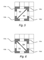
- the defining of the two triangles may be content adaptive, in the sense that based on the differences between diagonally positioned pixels, different diagonal settings of the triangles may be employed. This is shown in figures 5-6 where figure 5 shows two triangles 602, 604.
- the first triangle 602 is formed by the pixel positions 106a, 106b, and 106c, while the second triangle 604 is formed by the pixel positions 106b, 106c and 106d.
- another diagonal setting is used.
- the first triangle 702 is formed by the pixel positions 106a, 106b, and 106d
- the second triangle 604 is formed by the pixel positions 106a, 106c and 106d.
- the selection between the diagonal settings may be done by calculating, by the geometry shader, a first difference between the color components corresponding to a upper left pixel position 106a in the quad, and a lower right pixel position 106d in the quad, and a second difference between the color components corresponding to a upper right pixel position 106c in the quad, and a lower left pixel position 106b in the quad.
- the first difference is larger than the second difference
- the diagonal setting shown in figure 5 is selected; else the diagonal setting shown in figure 6 is selected.
- this embodiment provides a decision point in the algorithm that substantially improves visual quality of the resulting demosaiced image.
- the interpolation is adaptive to the actual pixel values in the 3x3 pixel area (quad) and thus content adaptive. Consequently, the geometry shader may be arranged to, prior to the step of defining two instances of a triangle primitive type, calculate the above described differences and reorder S812 the pixel positions comprised in the instance of the patch primitive type in case it is needed, e.g. when the second difference is larger than the first difference.
- the built-in rasterization function of the GPU can be used for rasterization S816 of each instance of the triangle primitive outputted by the geometry shaders.
- the already existing, fixed function e.g. implemented in dedicated silicon in the GPU
- rasterization functionality can be used for providing that all pixel positions of the texture with color components of each of the first, second and third color.
- the raster data may be snapped to integer locations that are then culled and clipped (to draw the minimum number of pixels), and per-pixel attributes (e.g. the color component corresponding to the pixel position) are interpolated (from per-vertex attributes) before being passed to a pixel shader
- the rasterization rules of the GPU will be used for the rasterization, and example of such rules may be as defined for Direct3D version 11.
- each pixel position will now correspond to two color components of the third color, and one color component of the first color and one color component of the second color.
- each pixel position verex
- each pixel position has 4 attributes, one attribute defining the color component of the first color, one attribute defining the color component of the second color, and two attributes defining the color components of the third color.
- each pixel position of the texture and the corresponding components of the first, second and third color will now automatically be inputted to the pixel shader of the GPU.
- a complete image (all pixels of the image having a color component from each of the first, second and third color) may be formed.
- the pixel shader may perform an alpha blending operation. Consequently, the fixed function blend stage (using dedicated hardware of the GPU) may be employed for forming the final image.
- the alpha blending operation is performed on one of the color components corresponding to each pixel position inputted to the pixel shader.
- each color channel is added to the final image using four rendering operations at the pixel shader. For each rendering operation, the color component for 100% of the first color or 100% of the color component for the second color or the color component for 50% of the third color is generated.
- the pixel shader needs to, for each inputted pixel position of the texture and the corresponding color components of each of the first, second and third color, divide the corresponding color component of the third color by 2 (or multiplying with 0.5) before outputting the pixel position and the corresponding color components of each of the first, second and third color.
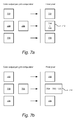
- the alpha blending operation is shown in figure 7a , and is thus a single pass solution where an additive blend is performed on color components 704, 705 (from the third color) which thus forms color component 712 (from the third color) in the final pixel.
- the final pixel is thus a pixel having an R-component 702, a G-component 712 and a B-component 706.
- no blending operation is performed by the pixel shader.
- the pixel shader is, for each inputted pixel position of the texture and the corresponding color components of each of the first, second and third color, outputting the pixel position and corresponding color components of each of the first, second and third color.
- the pixel shader outputs the interpolated colors of the first, second and third color for each pixel position.
- the final image is formed by, for each pixel position, combining the corresponding color component of the first color, the corresponding color component of the second color and the two corresponding color components of the third color. Pseudo code for this may be as follow:
- the color component of the third color (e.g. green) is formed by adding the two color components 708, 709 of the third color (which where the outcome from the built-in rasterization function) and dividing the added values by 2 (or multiplying with 0.5) to form the final color component 714 of the third color.
- the final pixel is thus a pixel having an R-component 702, a G-component 714 and a B-component 706.
- any of the combination functions for this embodiment may also include weight or similar for the color channels and this embodiment may thus be more flexible than performing the blending in the pixel shader (as shown in figure 7a and described above).
Landscapes
- Engineering & Computer Science (AREA)
- Physics & Mathematics (AREA)
- General Physics & Mathematics (AREA)
- Theoretical Computer Science (AREA)
- Computer Vision & Pattern Recognition (AREA)
- Image Processing (AREA)
- Color Television Image Signal Generators (AREA)
Abstract
Description
- The present disclosure generally relates to the field of demosaicing an image captured by an image sensor a color filter array, and more specifically relate to such a demosaicing operation using the GPU, shaders of the GPU and built-in rasterization function of the GPU.
- A demosaicing (also de-mosaicing, demosaicking or debayering) algorithm is a digital image process used to reconstruct a full color image from the incomplete color samples output from an image sensor overlaid with a color filter array (CFA). It is also known as CFA interpolation or color reconstruction.
- These days it is common to do advanced image processing on GPUs (Graphics Processor Units), since the GPUs provide high performance and better energy efficiency compared to perform the processing on the CPU (Central Processing Unit).
- It would thus be advantageous to do the bayer demosaicing on the GPU as well, but preferably in a more energy efficient way than the standard pixel or compute shaders described in prior art.
- It is within this context that the present disclosure lies.
- In view of the above, an objective of the invention is to solve or at least reduce one or several of the drawbacks discussed above. Generally, the above objective is achieved by the attached independent patent claims.
- According to a first aspect of the present invention, this and other objectives are achieved by a method for demosaicing an image captured by an image sensor comprising a color filter array, the method comprising the steps of:
- receiving, by a graphical processing unit, GPU, a texture corresponding to the captured image, the texture having a mosaic pattern with a first, second and third color, each pixel in the texture having a color component from only one color of said first, second and third color, wherein 25% of the pixels in the texture have a color component from the first color, wherein 25% of the pixels in the texture have a color component from the second color, wherein 50% of the pixels in the texture have a color component from the third color,
- from the texture, defining four grids, each grid defining a plurality of pixel positions in the texture, wherein a first grid define pixel positions of all pixels of the texture having a color component from the first color, wherein a second grid define pixel positions of all pixels of the texture having a color component from the second color, wherein a third grid define pixel positions of 50% of the pixels of the texture having a color component from the third color, wherein a fourth grid define pixel positions of a remaining 50% of the pixels of the texture having a color component from the third color,
- for each grid and each pixel position in the grid, initiating a vertex shader of the GPU and provide as an input to the vertex shader the pixel position, wherein the vertex shader extracts the color component corresponding to the pixel position in the texture and outputs the pixel position and the corresponding color component of the pixel position,
- for each grid and using the output from the vertex shaders, defining a plurality instances of a patch primitive type, each instance of the patch primitive type comprising four pixel positions forming a quad, and the color component corresponding to each of the four pixel positions,
- for each instance of the patch primitive type, initiating a geometry shader of the GPU, and provide as a input to the geometry shader the instance of the patch primitive type, wherein the geometry shader define two instances of a triangle primitive type from the instance of the patch primitive type based on an order of the pixel positions comprised in the instance of the patch primitive type, wherein each instance of the triangle primitive type comprises three pixel positions forming a triangle, and the color components corresponding to each of the three pixel positions, and output the two instances of the triangle primitive type,
- using a built-in rasterization function of the GPU for rasterization of each instance of the triangle primitive outputted by the geometry shaders of the GPU, such that all pixel positions of the texture each corresponds to a color component of the first color, a color component of the second color and two color components of the third color,
- inputting each pixel position of the texture and the corresponding color components of each of the first, second and third color to a pixel shader of the GPU, and
- forming an image based on outputs of the pixel shader, wherein all pixels of the image having a color component from each of the first, second and third color.
- By the term "patch primitive type" (or just "patch") should, in the context of present specification, be understood a data structure (primitive) with a user-defined number of vertices, for example four pixel positions forming a quad. This primitive is supported by some GPUs, for example those implementing OpenGL 4 or later, or Direct3D 11 or later. Each patch of vertex data may be subdivided into smaller primitives in the rendering pipeline (also known as Tessellation).
- By the term triangle primitive type" (or just "triangle") should, in the context of present specification, be understood a data structure (primitive) formed by 3 vertices.
- The built-in rasterization function of the GPU may function as described in the rastarization rules for Direct3D 11. Any other suitable rasterization rule may apply.
- In the context of the present specification, all data elements processed before the rasterization step are stored within vertex points. In other words, the data points of the grids originate from the pixel positions of the texture but in this context may be considered as vertex points containing pixel position data.
- It should be noted that the input to the vertex shader should be the pixel center positions, i.e. x+0.5, y+0.5. Consequently, the first, second, third and fourth grid may define such pixel center positions. According to other embodiments, the grids define e.g. x and y, and the addition of the 0.5 to each of the x-, and y-value is made before inputting the value to the vertex shader.
- It should be noted that by specifying the output type of the geometry shader as two triangle primitive types, the Tessellation process (e.g. defining of the two triangles) may be done implicitly during execution of the shader. In other words, the geometry shader will define two instances of the triangle primitive type from the instance of the patch primitive type.
- Since two grids defining the pixel positions the pixels of the texture having a color component from the third color exist, i.e. a third grid define pixel positions of 50% of the pixels of the texture having a color component from the third color, wherein a fourth grid define pixel positions of a remaining 50% of the pixels of the texture having a color component from the third color, each pixel position will after rasterization correspond to two color components of the third color. These two will then be blended together or otherwise added to each other, to form a single color component in the final image, as will be further described below.
- The inventors have realized that by using the built-in rasterization function of the GPU, which includes an interpolator in fixed-function silicon/hardware (which is normally used by the rasterization stage of the 3D graphics pipeline), an energy consumption similar to a dedicated camera processing chip (which typically has the Bayer interpolator implemented as fixed function hardware) can be achieved when performing Bayer demosaicing. Consequently, the functionality of such dedicated camera processing chip can be implemented by the GPU and a more cost efficient Bayer demosaicing can be achieved.
- According to some embodiments, the method further comprises the steps of: prior to the step of defining two instances of a triangle primitive type by the geometry shader, calculating, by the geometry shader, a first difference between the color components corresponding to a upper left pixel position in the quad, and a lower right pixel position in the quad, and a second difference between the color components corresponding to a upper right pixel position in the quad, and a lower left pixel position in the quad, and reorder the pixel positions comprised in the instance of the patch primitive type in case the second difference is larger than the first difference.
- Since the method operates on 3x3 pixel quads, the geometry shader can order the pixel positions in the quad such that the rasterization can be done with either of two different diagonal settings. In order to choose the best diagonal partitioning of the quad, the absolute difference between the diagonally positioned pixels in the quad may be calculated. Advantageously, this may improve the resulting image quality of the interpolation when there is edges present in the region defined by the pixel positions in the quad.
- In a second aspect, the present invention provides a computer program product comprising a computer-readable storage medium with instructions adapted to carry out the method of any one of claims 1-8 when executed by a device having processing capability.
- In a third aspect, the present invention provides a graphical processing unit, GPU, arranged for demosaicing an image captured by an image sensor comprising a color filter array, wherein the GPU is arranged to:
- receiving a texture corresponding to the captured image, the texture having a mosaic pattern with a first, second and third color, each pixel in the texture having a color component from only one color of said first, second and third color, wherein 25% of the pixels in the texture have a color component from the first color, wherein 25% of the pixels in the texture have a color component from the second color, wherein 50% of the pixels in the texture have a color component from the third color,
- from the texture, defining four grids, each grid defining a plurality of pixel positions in the texture, wherein a first grid define pixel positions of all pixels of the texture having a color component from the first color, wherein a second grid define pixel positions of all pixels of the texture having a color component from the second color, wherein a third grid define pixel positions of 50% of the pixels of the texture having a color component from the third color, wherein a fourth grid define pixel positions of a remaining 50% of the pixels of the texture having a color component from the third color,
- for each grid and each pixel position in the grid, initiating a vertex shader and provide as a input to the vertex shader the pixel position, wherein the vertex shader extracts the color component corresponding to the pixel position in the texture and outputs the pixel position and the corresponding color component of the pixel position,
- for each grid and using the output from the vertex shaders, defining a plurality instances of a patch primitive type, each instance of the patch primitive type comprising four pixel positions forming a quad, and the color component corresponding to each of the four pixel positions ,
- for each instance of the patch primitive type, initiating a geometry shader, and provide as a input to the geometry shader the instance of the patch primitive type, wherein the geometry shader define two instances of a triangle primitive type from the instance of the patch primitive type based on a order of the pixel positions comprised in the instance of the patch primitive type, wherein each instance of the triangle primitive type comprises three pixel positions forming a triangle, and the color components corresponding to each of the three pixel positions, and output the two instances of the triangle primitive type,
- using a built-in rasterization function for rasterization of each instance of the triangle primitive outputted by the geometry shaders, such that all pixel positions of the texture each corresponds to a color component of the first color, a color component of the second color and two color components of the third color,
- inputting each pixel position of the texture and the corresponding color components of each of the first, second and third color to a pixel shader, and
- forming an image based on outputs of the pixel shader, wherein all pixels of the image having a color component from each of the first, second and third color.
- The second and third aspect may generally have the same features and advantages as the first aspect.
- Other objectives, features and advantages of the present invention will appear from the following detailed disclosure, from the attached dependent claims as well as from the drawings.
- Generally, all terms used in the claims are to be interpreted according to their ordinary meaning in the technical field, unless explicitly defined otherwise herein. All references to "a/an/the [element, device, component, means, step, etc]" are to be interpreted openly as referring to at least one instance of the element, device, component, means, step, etc., unless explicitly stated otherwise.
- The above, as well as additional objects, features and advantages of the present invention, will be better understood through the following illustrative and non-limiting detailed description of embodiments of the present invention, with reference to the appended drawings, where the same reference numerals will be used for similar elements, wherein:
-
figure 1 shows a color filter array with a Bayer pattern, -
figure 2 shows four grids defined by the GPU from the Bayer pattern offigure 1 , -
figure 3 shows by way of example a rasterization of a mosaiced image received by the GPU, using a fixed function interpolator of the GPU, -
figure 4 shows rasterization according tofigure 3 for adjacent quads, -
figures 5-6 show ways of rasterization a quad, using two different diagonal settings, -
figures 7a-b show two ways of defining color components of a final pixel according to embodiments, -
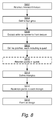
figure 8 shows a method for demosaicing an image captured by an image sensor comprising a color filter array. - A demosaicing (also de-mosaicing, demosaicking or debayering) algorithm is a digital image process used to reconstruct a full color image from the incomplete color samples output from an image sensor overlaid with a color filter array (CFA). It is also known as CFA interpolation or color reconstruction. Such an
incomplete color sample 100, e.g. animage 100 captured by an image sensor comprising a CFA, is shown infigure 1 . Thecolor sample 100 has a mosaic pattern with a first 104, second 106, 108 and third 102 color. Sinceimage 100 are captured with a by an image sensor comprising a CFA (e.g. a RGBG filter, GRGB filter, RGGB filter and a CYYM filter), each pixel in the image has a color component from only one color of said first, second and third color. As can be seen infigure 1 , 25% of the pixels in the texture have a color component from thefirst color 104, 25% of the pixels in the texture have a color component from thesecond color 106, and 50% of the pixels in the texture have a color component from thethird color 102. - In the following, the CFA is exemplified as a RGBG filter, and the
first color 104 thus corresponds to red, thesecond color 106 corresponds to blue and thethird color 102 corresponds to green. - With demosaicing, the missing colors for each pixel are created. In the RGBG case, 3 cases exist. If the pixel is a "green pixel" 102 (the green color component), the red and blue color components have to be created. If the pixel is a "blue pixel" 106 (the blue color component), the red and green color components have to be created. If the pixel is a "red pixel" 104 (the red color component), the green and blue color component have to be created. Typically, demosaicing is done using interpolation in a hardware specifically dedicated for the demosaicing operation. For example, for the
blue pixel 108, the following steps need to be performed: - Calculate the red component of
pixel 108 by calculating the average of the 4 surrounding red pixels. - Calculate the green component of
pixel 108 by calculating the average of the 4 surrounding green pixels. - After this, we have all 3 components of
pixel 108. - The similar thing needs to be done to the rest of the pixels in the
image 100. - However, the inventors have realized that if the GPU could be used for the interpolation, a much more energy efficient and cost efficient demosaicing method can be achieved since no additional hardware is needed and since the image data is transferred to the GPU anyway for further processing. Such methods, devices and computer program products will now be described in conjunction with
figures 2-8 . - As mentioned above, the GPU will receive S802 a texture corresponding to the captured
image 100. This is thus the raw image as captured by the image sensor of the camera. The texture have a mosaic pattern with a first 104, second 106, 108 and third 102 color, each pixel in the texture having a color component from only one color of said first, second and third color, wherein 25% of the pixels in the texture have a color component from the first color 104 (e.g. red), wherein 25% of the pixels in the texture have a color component from the second color 106 (e.g. blue), wherein 50% of the pixels in the texture have a color component from the third color 102 (e.g. green). - From the texture, the GPU may define S804 four grids 202-208, shown in
figure 2 . Thefirst grid 202 defines pixel positions of all pixels of the texture having a color component from the first color 104 (red). Thesecond grid 204 defines pixel positions of all pixels of the texture having a color component from the second color 106 (blue). Thethird grid 206 defines pixel positions of 50% of the pixels of the texture having a color component from the third color 102 (green). Thefourth grid 208 defines pixel positions of a remaining 50% of the pixels of the texture having a color component from the third color 102 (green). By dividing the green pixels into twogrids tree colors - According to some embodiment, the GPU may extract metadata defining a mosaic pattern from the texture, and defining the four grids based on the metadata. This may decrease the computational complexity. According to other embodiments, the mosaic pattern is defined by e.g. analyzing a small bit of the input texture, to extract the pattern. This may increase the flexibility since no metadata may be needed to define the pattern. According to some embodiments, the second, third and fourth grid is defined by shifting the positions of the first grid according to a predefined rule. Consequently, only one grid with pixel positions needs to be defined and stored in memory since the second, third and fourth grid with their respective pixel positions may be deduced from the one grid defined and stored in memory. In case the captured image always is of the same size, the grid may be hardcoded in memory. Otherwise, the size may be read from the captured image.
- After the four grids 202-208 have been defined, the color components for each pixel position in the grids 202-208 need to be extracted S806. This may be done by, for each grid and each pixel position in the grid, initiating a vertex shader of the GPU and provide as an input to the vertex shader the pixel position. The input to a vertex shader is thus a single pixel position, and the output of the vertex shader is the pixel position and the corresponding color component of the pixel position, i.e. the color component from the pixel position in the texture having the mosaiced pattern. According to some embodiments, the extraction of the color value for each pixel positions defined in a grid 202-208 may be performed in parallel. In other words, in case a grid 202-208 comprises e.g. 200 pixel positions, 200 vertex shaders may be initiated in parallel. Each of the 200 vertex shaders may then in parallel extract the respective color component by reading directly from the texture memory of the GPU. This may increase the speed of the demosaicing operation in the GPU.
- The output from the vertex shaders are vertex points containing pixel position data and corresponding color component data of the pixel position data, read from the texture as described above..
- After this, patches (patch primitive types) are instantiated and defined S810, where each instance of a patch comprises four pixel positions forming a quad, and the color component corresponding to each of the four pixel positions. The content of a patch is exemplified in
figure 3 where fourpixel positions 106a-d forms aquad 302, and where the color components (blue in this case) of thepixel positions 106a-d extracted by the vertex shaders also are included in the patch. - For each such instance the patch primitive type, a geometry shader of the GPU may be initiated. The input the geometry shader is the instance of the patch primitive type. The geometry shader may be arranged to define S814 two instances of a triangle primitive type from the instance of the patch primitive type based on an order of the pixel positions comprised in the instance of the patch primitive type. As described above, a triangle is a data structure formed by 3 vertices, and consequently, each instance of the triangle primitive type comprises three pixel positions forming a triangle, and the color components corresponding to each of the three pixel positions. The two defined instances of the triangle are then outputted from the geometry shader.
- As can be seen in
figure 4 ,adjacent quads quad 302 is defined by thepixel positions 106a-d, and thequad 402 is defined by the pixel positions 106b, 106d, 106e, 106g, thus sharing two vertices with the neighboringquad 302. - According to some embodiments, the defining of the two triangles may be content adaptive, in the sense that based on the differences between diagonally positioned pixels, different diagonal settings of the triangles may be employed. This is shown in
figures 5-6 wherefigure 5 shows twotriangles first triangle 602 is formed by thepixel positions second triangle 604 is formed by the pixel positions 106b, 106c and 106d. Infigure 6 , another diagonal setting is used. In this setting, thefirst triangle 702 is formed by thepixel positions second triangle 604 is formed by thepixel positions left pixel position 106a in the quad, and a lowerright pixel position 106d in the quad, and a second difference between the color components corresponding to a upperright pixel position 106c in the quad, and a lowerleft pixel position 106b in the quad. In case the first difference is larger than the second difference, the diagonal setting shown infigure 5 is selected; else the diagonal setting shown infigure 6 is selected. By doing this, the interpolation (to be described below) when there is an edge present in the region defined by the quad are improved. In other words, this embodiment provides a decision point in the algorithm that substantially improves visual quality of the resulting demosaiced image. With this addition, the interpolation is adaptive to the actual pixel values in the 3x3 pixel area (quad) and thus content adaptive. Consequently, the geometry shader may be arranged to, prior to the step of defining two instances of a triangle primitive type, calculate the above described differences and reorder S812 the pixel positions comprised in the instance of the patch primitive type in case it is needed, e.g. when the second difference is larger than the first difference. - After the triangles have been defined, the built-in rasterization function of the GPU can be used for rasterization S816 of each instance of the triangle primitive outputted by the geometry shaders. In this ways, the already existing, fixed function (e.g. implemented in dedicated silicon in the GPU) rasterization functionality can be used for providing that all pixel positions of the texture with color components of each of the first, second and third color. In this step, the raster data may be snapped to integer locations that are then culled and clipped (to draw the minimum number of pixels), and per-pixel attributes (e.g. the color component corresponding to the pixel position) are interpolated (from per-vertex attributes) before being passed to a pixel shader
- The rasterization rules of the GPU will be used for the rasterization, and example of such rules may be as defined for Direct3D version 11.
- Since two grids exist for the third color (e.g. green), each pixel position will now correspond to two color components of the third color, and one color component of the first color and one color component of the second color. In other words, each pixel position (vertex) has 4 attributes, one attribute defining the color component of the first color, one attribute defining the color component of the second color, and two attributes defining the color components of the third color.
- By using the built-in rasterization function of the GPU, each pixel position of the texture and the corresponding components of the first, second and third color will now automatically be inputted to the pixel shader of the GPU.
- Based on the outputs of the pixel shader, a complete image (all pixels of the image having a color component from each of the first, second and third color) may be formed. According to some embodiments, the pixel shader may perform an alpha blending operation. Consequently, the fixed function blend stage (using dedicated hardware of the GPU) may be employed for forming the final image. The alpha blending operation is performed on one of the color components corresponding to each pixel position inputted to the pixel shader. In this embodiment, each color channel is added to the final image using four rendering operations at the pixel shader. For each rendering operation, the color component for 100% of the first color or 100% of the color component for the second color or the color component for 50% of the third color is generated. Consequently, in case the alpha blending operation by the pixel shader is performed on the color component of the third channel, the pixel shader needs to, for each inputted pixel position of the texture and the corresponding color components of each of the first, second and third color, divide the corresponding color component of the third color by 2 (or multiplying with 0.5) before outputting the pixel position and the corresponding color components of each of the first, second and third color. The alpha blending operation is shown in
figure 7a , and is thus a single pass solution where an additive blend is performed oncolor components 704, 705 (from the third color) which thus forms color component 712 (from the third color) in the final pixel. In this example, the final pixel is thus a pixel having an R-component 702, a G-component 712 and a B-component 706. - In another embodiment, no blending operation is performed by the pixel shader. In this case, the pixel shader is, for each inputted pixel position of the texture and the corresponding color components of each of the first, second and third color, outputting the pixel position and corresponding color components of each of the first, second and third color. In other words, the pixel shader outputs the interpolated colors of the first, second and third color for each pixel position. In this embodiment, the final image is formed by, for each pixel position, combining the corresponding color component of the first color, the corresponding color component of the second color and the two corresponding color components of the third color. Pseudo code for this may be as follow:

- To form the final pixel, a second calculation is needed, shown in
figure 7b where the color component of the third color (e.g. green) is formed by adding the twocolor components final color component 714 of the third color. In this example, the final pixel is thus a pixel having an R-component 702, a G-component 714 and a B-component 706. - However, any of the combination functions for this embodiment may also include weight or similar for the color channels and this embodiment may thus be more flexible than performing the blending in the pixel shader (as shown in
figure 7a and described above).
Claims (15)
- A method for demosaicing an image (100) captured by an image sensor comprising a color filter array, the method comprising the steps of:receiving (S802), by a graphical processing unit, GPU, a texture corresponding to the captured image, the texture having a mosaic pattern with a first (104), second (106, 108) and third (102) color, each pixel in the texture having a color component from only one color of said first, second and third color, wherein 25% of the pixels in the texture have a color component from the first color, wherein 25% of the pixels in the texture have a color component from the second color, wherein 50% of the pixels in the texture have a color component from the third color,from the texture, defining (S804) four grids (202, 204, 206, 208), each grid defining a plurality of pixel positions in the texture, wherein a first grid define pixel positions of all pixels of the texture having a color component from the first color, wherein a second grid define pixel positions of all pixels of the texture having a color component from the second color, wherein a third grid define pixel positions of 50% of the pixels of the texture having a color component from the third color, wherein a fourth grid define pixel positions of a remaining 50% of the pixels of the texture having a color component from the third color,for each grid and each pixel position in the grid, initiating a vertex shader of the GPU and provide as an input to the vertex shader the pixel position, wherein the vertex shader extracts the color component corresponding to the pixel position in the texture and outputs the pixel position and the corresponding color component of the pixel position,for each grid and using the output from the vertex shaders, defining a plurality instances of a patch primitive type, each instance of the patch primitive type comprising four pixel positions forming a quad (302, 402, 404), and the color component corresponding to each of the four pixel positions,for each instance of the patch primitive type, initiating a geometry shader of the GPU, and provide as a input to the geometry shader the instance of the patch primitive type, wherein the geometry shader define (S814) two instances of a triangle primitive type from the instance of the patch primitive type based on an order of the pixel positions comprised in the instance of the patch primitive type, wherein each instance of the triangle primitive type comprises three pixel positions forming a triangle (602, 604, 702, 704), and the color components corresponding to each of the three pixel positions, and output the two instances of the triangle primitive type,using a built-in rasterization function of the GPU for rasterization (S816) of each instance of the triangle primitive outputted by the geometry shaders of the GPU, such that all pixel positions of the texture each corresponds to a color component of the first color component, a color component of the second color and two color components of the third color,inputting each pixel position of the texture and the corresponding color components of each of the first, second and third color to a pixel shader of the GPU, andforming (S818) an image based on outputs of the pixel shader, wherein all pixels of the image having a color component from each of the first, second and third color.
- The method of claim 1, further comprising the steps of:prior to the step of defining two instances of a triangle primitive type by the geometry shader,calculating, by the geometry shader, a first difference between the color components corresponding to a upper left pixel position in the quad, and a lower right pixel position in the quad, and a second difference between the color components corresponding to a upper right pixel position in the quad, and a lower left pixel position in the quad, and reorder the pixel positions comprised in the instance of the patch primitive type in case the second difference is larger than the first difference.
- The method of any one of claims 1-2, further comprising the step of:extracting metadata defining a mosaic pattern from the texture, wherein the step of defining the four grids is performed based on the metadata.
- The method of any one of claims 1-3, wherein the second, third and fourth grid is defined by shifting the positions of the first grid according to a predefined rule.
- The method of any one of claims 1-4, further comprising the step of:performing an alpha blending operation by the pixel shader on one of the color components corresponding to each pixel position inputted to the pixel shader.
- The method of claim 5, wherein the alpha blending operation by the pixel shader is performed on the color component of the third channel, wherein the method further comprises the step of:by the pixel shader, for each inputted pixel position of the texture and the corresponding color components of each of the first, second and third color, dividing the corresponding color component of the third color by 2 before outputting the pixel position and the corresponding color components of each of the first, second and third color.
- The method of any one of claims 1-4, further comprises the steps of:by the pixel shader, for each inputted pixel position of the texture and the corresponding color components of each of the first, second and third color, outputting the pixel position and corresponding color components of each of the first, second and third color, and wherein the step of forming an image comprises:for each pixel position, combining the corresponding color component of the first color, the corresponding color component of the second color and the two corresponding color components of the third color.
- The method of any one of claims 1-7, wherein the color filter array corresponds to one from the list of: a RGBG filter, GRGB filter, RGGB filter and a CYYM filter.
- A computer program product comprising a computer-readable storage medium with instructions adapted to carry out the method of any one of claims 1-8 when executed by a device having processing capability.
- A graphical processing unit, GPU, arranged for demosaicing an image captured by an image sensor comprising a color filter array, wherein the GPU is arranged to:receiving an texture corresponding to the captured image, the texture having a mosaic pattern with a first, second and third color, each pixel in the texture having a color component from only one color of said first, second and third color, wherein 25% of the pixels in the texture have a color component from the first color, wherein 25% of the pixels in the texture have a color component from the second color, wherein 50% of the pixels in the texture have a color component from the third color,from the texture, defining four grids, each grid defining a plurality of pixel positions in the texture, wherein a first grid define pixel positions of all pixels of the texture having a color component from the first color, wherein a second grid define pixel positions of all pixels of the texture having a color component from the second color, wherein a third grid define pixel positions of 50% of the pixels of the texture having a color component from the third color, wherein a fourth grid define pixel positions of a remaining 50% of the pixels of the texture having a color component from the third color,for each grid and each pixel position in the grid, initiating a vertex shader and provide as a input to the vertex shader the pixel position, wherein the vertex shader extracts the color component corresponding to the pixel position in the texture and outputs the pixel position and the corresponding color component of the pixel position,for each grid and using the output from the vertex shaders, defining a plurality instances of a patch primitive type, each instance of the patch primitive type comprising four pixel positions forming a quad, and the color component corresponding to each of the four pixel positions ,for each instance of the patch primitive type, initiating a geometry shader, and provide as a input to the geometry shader the instance of the patch primitive type, wherein the geometry shader define two instances of a triangle primitive type from the instance of the patch primitive type based on an order of the pixel positions comprised in the instance of the patch primitive type, wherein each instance of the triangle primitive type comprises three pixel positions forming a triangle, and the color components corresponding to each of the three pixel positions, and output the two instances of the triangle primitive type,using a built-in rasterization function for rasterization of each instance of the triangle primitive outputted by the geometry shaders, such that all pixel positions of the texture each corresponds to a color component of the first color, a color component of the second color and two color components of the third color,inputting each pixel position of the texture and the corresponding color components of each of the first, second and third color to a pixel shader, andforming an image based on outputs of the pixel shader, wherein all pixels of the image having a color component from each of the first, second and third color.
- The GPU of claim 10, further being adapted for:prior to defining two instances of a triangle primitive type by the geometry shader,calculating, by the geometry shader, a first difference between the color components corresponding to a upper left pixel position in the quad, and a lower right pixel position in the quad, and a second difference between the color components corresponding to a upper right pixel position in the quad, and a lower left pixel position in the quad, and reorder the pixel positions comprised in the instance of the patch primitive type in case the second difference is larger than the first difference.
- The GPU of any one of claims 10-11, further being adapted for extracting metadata defining a mosaic pattern from the texture, wherein the step of defining the four grids is performed based on the metadata.
- The GPU of any one of claims 10-12, further being adapted for defining the second, third and fourth grid by shifting the positions of the first grid according to a predefined rule.
- The GPU of any one of claims 10-13, further being adapted for performing an alpha blending operation by the pixel shader on one of the color components corresponding to each pixel position inputted to the pixel shader.
- The GPU of any one of claims 10-13, further being adapted for:by the pixel shader, for each inputted pixel position of the texture and the corresponding color components of each of the first, second and third color, outputting the pixel position and corresponding color components of each of the first, second and third color, and wherein the step of forming an image comprises:for each pixel position, combining the corresponding color component of the first color, the corresponding color component of the second color and the two corresponding color components of the third color.
Priority Applications (2)
| Application Number | Priority Date | Filing Date | Title |
|---|---|---|---|
| EP16170899.5A EP3249604B1 (en) | 2016-05-23 | 2016-05-23 | Methods, devices and computer program products for demosaicing an image captured by an image sensor comprising a color filter array |
| US15/594,641 US10255660B2 (en) | 2016-05-23 | 2017-05-14 | Methods, devices and computer program products for demosaicing an image captured by an image sensor comprising a color filter array |
Applications Claiming Priority (1)
| Application Number | Priority Date | Filing Date | Title |
|---|---|---|---|
| EP16170899.5A EP3249604B1 (en) | 2016-05-23 | 2016-05-23 | Methods, devices and computer program products for demosaicing an image captured by an image sensor comprising a color filter array |
Publications (2)
| Publication Number | Publication Date |
|---|---|
| EP3249604A1 true EP3249604A1 (en) | 2017-11-29 |
| EP3249604B1 EP3249604B1 (en) | 2019-06-26 |
Family
ID=56080274
Family Applications (1)
| Application Number | Title | Priority Date | Filing Date |
|---|---|---|---|
| EP16170899.5A Active EP3249604B1 (en) | 2016-05-23 | 2016-05-23 | Methods, devices and computer program products for demosaicing an image captured by an image sensor comprising a color filter array |
Country Status (2)
| Country | Link |
|---|---|
| US (1) | US10255660B2 (en) |
| EP (1) | EP3249604B1 (en) |
Families Citing this family (7)
| Publication number | Priority date | Publication date | Assignee | Title |
|---|---|---|---|---|
| KR20180038793A (en) * | 2016-10-07 | 2018-04-17 | 삼성전자주식회사 | Method and apparatus for processing image data |
| US10885676B2 (en) * | 2016-12-27 | 2021-01-05 | Samsung Electronics Co., Ltd. | Method and apparatus for modifying display settings in virtual/augmented reality |
| US10922203B1 (en) * | 2018-09-21 | 2021-02-16 | Nvidia Corporation | Fault injection architecture for resilient GPU computing |
| CN109658358B (en) * | 2018-12-25 | 2023-05-12 | 辽宁工程技术大学 | Rapid Bayer color reconstruction method based on multi-guide filtering |
| EP3812801B1 (en) | 2019-10-23 | 2024-06-19 | Samsung Electronics Co., Ltd. | Image sensor including color separating lens array and electronic device including the image sensor |
| CN112701132B (en) | 2019-10-23 | 2025-08-22 | 三星电子株式会社 | Image sensor and electronic device including the same |
| US12112420B2 (en) | 2021-12-07 | 2024-10-08 | Samsung Electronics Co., Ltd. | Method and apparatus for improving the image quality of variable rate shading using gradients |
Citations (2)
| Publication number | Priority date | Publication date | Assignee | Title |
|---|---|---|---|---|
| US20120026178A1 (en) * | 2006-02-06 | 2012-02-02 | Microsoft Corporation | Raw image processing |
| US20160217548A1 (en) * | 2015-01-28 | 2016-07-28 | Qualcomm Incorporated | Graphics processing unit with bayer mapping |
Family Cites Families (1)
| Publication number | Priority date | Publication date | Assignee | Title |
|---|---|---|---|---|
| US6816197B2 (en) * | 2001-03-21 | 2004-11-09 | Hewlett-Packard Development Company, L.P. | Bilateral filtering in a demosaicing process |
-
2016
- 2016-05-23 EP EP16170899.5A patent/EP3249604B1/en active Active
-
2017
- 2017-05-14 US US15/594,641 patent/US10255660B2/en active Active
Patent Citations (2)
| Publication number | Priority date | Publication date | Assignee | Title |
|---|---|---|---|---|
| US20120026178A1 (en) * | 2006-02-06 | 2012-02-02 | Microsoft Corporation | Raw image processing |
| US20160217548A1 (en) * | 2015-01-28 | 2016-07-28 | Qualcomm Incorporated | Graphics processing unit with bayer mapping |
Non-Patent Citations (2)
| Title |
|---|
| GWANGGIL JEON: "Different Color Union for Single Sensor Interpolation", INTERNATIONAL JOURNAL OF CONTROL AND AUTOMATION, vol. 7, no. 2, 28 February 2014 (2014-02-28), KR, pages 397 - 404, XP055318056, ISSN: 2005-4297, DOI: 10.14257/ijca.2014.7.2.35 * |
| MORGAN MCGUIRE: "Efficient, High-Quality Bayer Demosaic Filtering on GPUs", JOURNAL OF GRAPHICS TOOLS, ASSOCIATION FOR COMPUTING MACHINERY, NEW YORK, US, vol. 13, no. 4, 2008, pages 1 - 16, XP009189618, ISSN: 1086-7651 * |
Also Published As
| Publication number | Publication date |
|---|---|
| EP3249604B1 (en) | 2019-06-26 |
| US10255660B2 (en) | 2019-04-09 |
| US20170337664A1 (en) | 2017-11-23 |
Similar Documents
| Publication | Publication Date | Title |
|---|---|---|
| EP3249604B1 (en) | Methods, devices and computer program products for demosaicing an image captured by an image sensor comprising a color filter array | |
| EP4220567B1 (en) | Graphics processing units and methods for controlling rendering complexity using cost indications for sets of tiles of a rendering space | |
| US9786091B2 (en) | Gradient adjustment for texture mapping to non-orthonormal grid | |
| Al-Dwairi et al. | Optimized true-color image processing | |
| CN109889800B (en) | Image enhancement method and device, electronic equipment and storage medium | |
| US9105106B2 (en) | Two-dimensional super resolution scaling | |
| US11983848B2 (en) | AI frame engine for mobile edge | |
| US11263805B2 (en) | Method of real-time image processing based on rendering engine and a display apparatus | |
| CN110852953B (en) | Image interpolation method and device, storage medium, image signal processor and terminal | |
| WO2022061879A1 (en) | Image processing method, apparatus and system, and computer-readable storage medium | |
| US8681180B2 (en) | Post-render graphics scaling | |
| US11238639B2 (en) | Gradient adjustment for texture mapping to non-orthonormal grid | |
| CN114040246A (en) | Image format conversion method, device, equipment and storage medium of graphic processor | |
| US20160063752A1 (en) | Rendering apparatus and method | |
| CN113424231B (en) | Apparatus and method for generating light intensity images | |
| US11037357B2 (en) | Pixelation optimized delta color compression | |
| US20180101980A1 (en) | Method and apparatus for processing image data | |
| CN106570924B (en) | Texture processing methods and units | |
| US7986358B1 (en) | Bayer image conversion using a graphics processing unit | |
| CN113793249B (en) | Pentile image conversion method and related equipment for RGB images | |
| US20240037701A1 (en) | Image processing and rendering | |
| US10970817B2 (en) | Image magnifying apparatus | |
| US8452090B1 (en) | Bayer reconstruction of images using a GPU | |
| CN116258644B (en) | Image enhancement method, device, computer equipment and storage medium | |
| US20130182000A1 (en) | System and method for rendering an image |
Legal Events
| Date | Code | Title | Description |
|---|---|---|---|
| PUAI | Public reference made under article 153(3) epc to a published international application that has entered the european phase |
Free format text: ORIGINAL CODE: 0009012 |
|
| STAA | Information on the status of an ep patent application or granted ep patent |
Free format text: STATUS: THE APPLICATION HAS BEEN PUBLISHED |
|
| AK | Designated contracting states |
Kind code of ref document: A1 Designated state(s): AL AT BE BG CH CY CZ DE DK EE ES FI FR GB GR HR HU IE IS IT LI LT LU LV MC MK MT NL NO PL PT RO RS SE SI SK SM TR |
|
| AX | Request for extension of the european patent |
Extension state: BA ME |
|
| STAA | Information on the status of an ep patent application or granted ep patent |
Free format text: STATUS: REQUEST FOR EXAMINATION WAS MADE |
|
| 17P | Request for examination filed |
Effective date: 20180419 |
|
| RBV | Designated contracting states (corrected) |
Designated state(s): AL AT BE BG CH CY CZ DE DK EE ES FI FR GB GR HR HU IE IS IT LI LT LU LV MC MK MT NL NO PL PT RO RS SE SI SK SM TR |
|
| GRAP | Despatch of communication of intention to grant a patent |
Free format text: ORIGINAL CODE: EPIDOSNIGR1 |
|
| STAA | Information on the status of an ep patent application or granted ep patent |
Free format text: STATUS: GRANT OF PATENT IS INTENDED |
|
| RIC1 | Information provided on ipc code assigned before grant |
Ipc: G06T 3/40 20060101AFI20181214BHEP |
|
| INTG | Intention to grant announced |
Effective date: 20190122 |
|
| GRAS | Grant fee paid |
Free format text: ORIGINAL CODE: EPIDOSNIGR3 |
|
| GRAA | (expected) grant |
Free format text: ORIGINAL CODE: 0009210 |
|
| STAA | Information on the status of an ep patent application or granted ep patent |
Free format text: STATUS: THE PATENT HAS BEEN GRANTED |
|
| AK | Designated contracting states |
Kind code of ref document: B1 Designated state(s): AL AT BE BG CH CY CZ DE DK EE ES FI FR GB GR HR HU IE IS IT LI LT LU LV MC MK MT NL NO PL PT RO RS SE SI SK SM TR |
|
| REG | Reference to a national code |
Ref country code: GB Ref legal event code: FG4D |
|
| REG | Reference to a national code |
Ref country code: CH Ref legal event code: EP |
|
| REG | Reference to a national code |
Ref country code: AT Ref legal event code: REF Ref document number: 1149183 Country of ref document: AT Kind code of ref document: T Effective date: 20190715 |
|
| REG | Reference to a national code |
Ref country code: IE Ref legal event code: FG4D |
|
| REG | Reference to a national code |
Ref country code: DE Ref legal event code: R096 Ref document number: 602016015799 Country of ref document: DE |
|
| REG | Reference to a national code |
Ref country code: NL Ref legal event code: FP |
|
| PG25 | Lapsed in a contracting state [announced via postgrant information from national office to epo] |
Ref country code: SE Free format text: LAPSE BECAUSE OF FAILURE TO SUBMIT A TRANSLATION OF THE DESCRIPTION OR TO PAY THE FEE WITHIN THE PRESCRIBED TIME-LIMIT Effective date: 20190626 Ref country code: LT Free format text: LAPSE BECAUSE OF FAILURE TO SUBMIT A TRANSLATION OF THE DESCRIPTION OR TO PAY THE FEE WITHIN THE PRESCRIBED TIME-LIMIT Effective date: 20190626 Ref country code: FI Free format text: LAPSE BECAUSE OF FAILURE TO SUBMIT A TRANSLATION OF THE DESCRIPTION OR TO PAY THE FEE WITHIN THE PRESCRIBED TIME-LIMIT Effective date: 20190626 Ref country code: AL Free format text: LAPSE BECAUSE OF FAILURE TO SUBMIT A TRANSLATION OF THE DESCRIPTION OR TO PAY THE FEE WITHIN THE PRESCRIBED TIME-LIMIT Effective date: 20190626 Ref country code: NO Free format text: LAPSE BECAUSE OF FAILURE TO SUBMIT A TRANSLATION OF THE DESCRIPTION OR TO PAY THE FEE WITHIN THE PRESCRIBED TIME-LIMIT Effective date: 20190926 Ref country code: HR Free format text: LAPSE BECAUSE OF FAILURE TO SUBMIT A TRANSLATION OF THE DESCRIPTION OR TO PAY THE FEE WITHIN THE PRESCRIBED TIME-LIMIT Effective date: 20190626 |
|
| REG | Reference to a national code |
Ref country code: LT Ref legal event code: MG4D |
|
| PG25 | Lapsed in a contracting state [announced via postgrant information from national office to epo] |
Ref country code: GR Free format text: LAPSE BECAUSE OF FAILURE TO SUBMIT A TRANSLATION OF THE DESCRIPTION OR TO PAY THE FEE WITHIN THE PRESCRIBED TIME-LIMIT Effective date: 20190927 Ref country code: BG Free format text: LAPSE BECAUSE OF FAILURE TO SUBMIT A TRANSLATION OF THE DESCRIPTION OR TO PAY THE FEE WITHIN THE PRESCRIBED TIME-LIMIT Effective date: 20190926 Ref country code: RS Free format text: LAPSE BECAUSE OF FAILURE TO SUBMIT A TRANSLATION OF THE DESCRIPTION OR TO PAY THE FEE WITHIN THE PRESCRIBED TIME-LIMIT Effective date: 20190626 Ref country code: LV Free format text: LAPSE BECAUSE OF FAILURE TO SUBMIT A TRANSLATION OF THE DESCRIPTION OR TO PAY THE FEE WITHIN THE PRESCRIBED TIME-LIMIT Effective date: 20190626 |
|
| REG | Reference to a national code |
Ref country code: AT Ref legal event code: MK05 Ref document number: 1149183 Country of ref document: AT Kind code of ref document: T Effective date: 20190626 |
|
| PG25 | Lapsed in a contracting state [announced via postgrant information from national office to epo] |
Ref country code: AT Free format text: LAPSE BECAUSE OF FAILURE TO SUBMIT A TRANSLATION OF THE DESCRIPTION OR TO PAY THE FEE WITHIN THE PRESCRIBED TIME-LIMIT Effective date: 20190626 Ref country code: EE Free format text: LAPSE BECAUSE OF FAILURE TO SUBMIT A TRANSLATION OF THE DESCRIPTION OR TO PAY THE FEE WITHIN THE PRESCRIBED TIME-LIMIT Effective date: 20190626 Ref country code: RO Free format text: LAPSE BECAUSE OF FAILURE TO SUBMIT A TRANSLATION OF THE DESCRIPTION OR TO PAY THE FEE WITHIN THE PRESCRIBED TIME-LIMIT Effective date: 20190626 Ref country code: CZ Free format text: LAPSE BECAUSE OF FAILURE TO SUBMIT A TRANSLATION OF THE DESCRIPTION OR TO PAY THE FEE WITHIN THE PRESCRIBED TIME-LIMIT Effective date: 20190626 Ref country code: PT Free format text: LAPSE BECAUSE OF FAILURE TO SUBMIT A TRANSLATION OF THE DESCRIPTION OR TO PAY THE FEE WITHIN THE PRESCRIBED TIME-LIMIT Effective date: 20191028 Ref country code: SK Free format text: LAPSE BECAUSE OF FAILURE TO SUBMIT A TRANSLATION OF THE DESCRIPTION OR TO PAY THE FEE WITHIN THE PRESCRIBED TIME-LIMIT Effective date: 20190626 |
|
| PG25 | Lapsed in a contracting state [announced via postgrant information from national office to epo] |
Ref country code: IS Free format text: LAPSE BECAUSE OF FAILURE TO SUBMIT A TRANSLATION OF THE DESCRIPTION OR TO PAY THE FEE WITHIN THE PRESCRIBED TIME-LIMIT Effective date: 20191026 Ref country code: IT Free format text: LAPSE BECAUSE OF FAILURE TO SUBMIT A TRANSLATION OF THE DESCRIPTION OR TO PAY THE FEE WITHIN THE PRESCRIBED TIME-LIMIT Effective date: 20190626 Ref country code: SM Free format text: LAPSE BECAUSE OF FAILURE TO SUBMIT A TRANSLATION OF THE DESCRIPTION OR TO PAY THE FEE WITHIN THE PRESCRIBED TIME-LIMIT Effective date: 20190626 Ref country code: ES Free format text: LAPSE BECAUSE OF FAILURE TO SUBMIT A TRANSLATION OF THE DESCRIPTION OR TO PAY THE FEE WITHIN THE PRESCRIBED TIME-LIMIT Effective date: 20190626 |
|
| PG25 | Lapsed in a contracting state [announced via postgrant information from national office to epo] |
Ref country code: TR Free format text: LAPSE BECAUSE OF FAILURE TO SUBMIT A TRANSLATION OF THE DESCRIPTION OR TO PAY THE FEE WITHIN THE PRESCRIBED TIME-LIMIT Effective date: 20190626 |
|
| PG25 | Lapsed in a contracting state [announced via postgrant information from national office to epo] |
Ref country code: DK Free format text: LAPSE BECAUSE OF FAILURE TO SUBMIT A TRANSLATION OF THE DESCRIPTION OR TO PAY THE FEE WITHIN THE PRESCRIBED TIME-LIMIT Effective date: 20190626 Ref country code: PL Free format text: LAPSE BECAUSE OF FAILURE TO SUBMIT A TRANSLATION OF THE DESCRIPTION OR TO PAY THE FEE WITHIN THE PRESCRIBED TIME-LIMIT Effective date: 20190626 |
|
| PG25 | Lapsed in a contracting state [announced via postgrant information from national office to epo] |
Ref country code: IS Free format text: LAPSE BECAUSE OF FAILURE TO SUBMIT A TRANSLATION OF THE DESCRIPTION OR TO PAY THE FEE WITHIN THE PRESCRIBED TIME-LIMIT Effective date: 20200224 |
|
| REG | Reference to a national code |
Ref country code: DE Ref legal event code: R097 Ref document number: 602016015799 Country of ref document: DE |
|
| PLBE | No opposition filed within time limit |
Free format text: ORIGINAL CODE: 0009261 |
|
| STAA | Information on the status of an ep patent application or granted ep patent |
Free format text: STATUS: NO OPPOSITION FILED WITHIN TIME LIMIT |
|
| PG2D | Information on lapse in contracting state deleted |
Ref country code: IS |
|
| 26N | No opposition filed |
Effective date: 20200603 |
|
| PG25 | Lapsed in a contracting state [announced via postgrant information from national office to epo] |
Ref country code: SI Free format text: LAPSE BECAUSE OF FAILURE TO SUBMIT A TRANSLATION OF THE DESCRIPTION OR TO PAY THE FEE WITHIN THE PRESCRIBED TIME-LIMIT Effective date: 20190626 |
|
| PG25 | Lapsed in a contracting state [announced via postgrant information from national office to epo] |
Ref country code: LI Free format text: LAPSE BECAUSE OF NON-PAYMENT OF DUE FEES Effective date: 20200531 Ref country code: CH Free format text: LAPSE BECAUSE OF NON-PAYMENT OF DUE FEES Effective date: 20200531 Ref country code: MC Free format text: LAPSE BECAUSE OF FAILURE TO SUBMIT A TRANSLATION OF THE DESCRIPTION OR TO PAY THE FEE WITHIN THE PRESCRIBED TIME-LIMIT Effective date: 20190626 |
|
| REG | Reference to a national code |
Ref country code: BE Ref legal event code: MM Effective date: 20200531 |
|
| GBPC | Gb: european patent ceased through non-payment of renewal fee |
Effective date: 20200523 |
|
| PG25 | Lapsed in a contracting state [announced via postgrant information from national office to epo] |
Ref country code: LU Free format text: LAPSE BECAUSE OF NON-PAYMENT OF DUE FEES Effective date: 20200523 |
|
| PG25 | Lapsed in a contracting state [announced via postgrant information from national office to epo] |
Ref country code: GB Free format text: LAPSE BECAUSE OF NON-PAYMENT OF DUE FEES Effective date: 20200523 Ref country code: IE Free format text: LAPSE BECAUSE OF NON-PAYMENT OF DUE FEES Effective date: 20200523 Ref country code: FR Free format text: LAPSE BECAUSE OF NON-PAYMENT OF DUE FEES Effective date: 20200531 |
|
| PG25 | Lapsed in a contracting state [announced via postgrant information from national office to epo] |
Ref country code: BE Free format text: LAPSE BECAUSE OF NON-PAYMENT OF DUE FEES Effective date: 20200531 |
|
| PG25 | Lapsed in a contracting state [announced via postgrant information from national office to epo] |
Ref country code: MT Free format text: LAPSE BECAUSE OF FAILURE TO SUBMIT A TRANSLATION OF THE DESCRIPTION OR TO PAY THE FEE WITHIN THE PRESCRIBED TIME-LIMIT Effective date: 20190626 Ref country code: CY Free format text: LAPSE BECAUSE OF FAILURE TO SUBMIT A TRANSLATION OF THE DESCRIPTION OR TO PAY THE FEE WITHIN THE PRESCRIBED TIME-LIMIT Effective date: 20190626 |
|
| PG25 | Lapsed in a contracting state [announced via postgrant information from national office to epo] |
Ref country code: MK Free format text: LAPSE BECAUSE OF FAILURE TO SUBMIT A TRANSLATION OF THE DESCRIPTION OR TO PAY THE FEE WITHIN THE PRESCRIBED TIME-LIMIT Effective date: 20190626 |
|
| P01 | Opt-out of the competence of the unified patent court (upc) registered |
Effective date: 20230527 |
|
| PGFP | Annual fee paid to national office [announced via postgrant information from national office to epo] |
Ref country code: NL Payment date: 20240418 Year of fee payment: 9 |
|
| PGFP | Annual fee paid to national office [announced via postgrant information from national office to epo] |
Ref country code: DE Payment date: 20240418 Year of fee payment: 9 |
|
| REG | Reference to a national code |
Ref country code: DE Ref legal event code: R119 Ref document number: 602016015799 Country of ref document: DE |
|
| REG | Reference to a national code |
Ref country code: NL Ref legal event code: MM Effective date: 20250601 |
|
| PG25 | Lapsed in a contracting state [announced via postgrant information from national office to epo] |
Ref country code: NL Free format text: LAPSE BECAUSE OF NON-PAYMENT OF DUE FEES Effective date: 20250601 |
|
| PG25 | Lapsed in a contracting state [announced via postgrant information from national office to epo] |
Ref country code: DE Free format text: LAPSE BECAUSE OF NON-PAYMENT OF DUE FEES Effective date: 20251202 |