EP3249433A1 - Optical transmission connector device - Google Patents
Optical transmission connector device Download PDFInfo
- Publication number
- EP3249433A1 EP3249433A1 EP15872481.5A EP15872481A EP3249433A1 EP 3249433 A1 EP3249433 A1 EP 3249433A1 EP 15872481 A EP15872481 A EP 15872481A EP 3249433 A1 EP3249433 A1 EP 3249433A1
- Authority
- EP
- European Patent Office
- Prior art keywords
- optical
- transmission
- side connector
- light
- reception
- Prior art date
- Legal status (The legal status is an assumption and is not a legal conclusion. Google has not performed a legal analysis and makes no representation as to the accuracy of the status listed.)
- Withdrawn
Links
- 230000003287 optical effect Effects 0.000 title claims abstract description 148
- 230000005540 biological transmission Effects 0.000 title claims abstract description 57
- 239000013307 optical fiber Substances 0.000 claims abstract description 58
- 238000005549 size reduction Methods 0.000 abstract description 5
- 210000001747 pupil Anatomy 0.000 description 9
- 230000008901 benefit Effects 0.000 description 4
- 230000009467 reduction Effects 0.000 description 3
- 230000004075 alteration Effects 0.000 description 2
- 238000003491 array Methods 0.000 description 2
- 230000000694 effects Effects 0.000 description 2
- 239000000835 fiber Substances 0.000 description 2
- 239000011347 resin Substances 0.000 description 2
- 229920005989 resin Polymers 0.000 description 2
- 230000007480 spreading Effects 0.000 description 2
- XLYOFNOQVPJJNP-UHFFFAOYSA-N water Substances O XLYOFNOQVPJJNP-UHFFFAOYSA-N 0.000 description 2
- 238000004140 cleaning Methods 0.000 description 1
- 239000011521 glass Substances 0.000 description 1
- 239000000463 material Substances 0.000 description 1
- 230000004048 modification Effects 0.000 description 1
- 238000012986 modification Methods 0.000 description 1
- 230000001681 protective effect Effects 0.000 description 1
Images



Classifications
-
- G—PHYSICS
- G02—OPTICS
- G02B—OPTICAL ELEMENTS, SYSTEMS OR APPARATUS
- G02B6/00—Light guides; Structural details of arrangements comprising light guides and other optical elements, e.g. couplings
- G02B6/24—Coupling light guides
- G02B6/36—Mechanical coupling means
- G02B6/38—Mechanical coupling means having fibre to fibre mating means
- G02B6/3807—Dismountable connectors, i.e. comprising plugs
- G02B6/3873—Connectors using guide surfaces for aligning ferrule ends, e.g. tubes, sleeves, V-grooves, rods, pins, balls
- G02B6/3885—Multicore or multichannel optical connectors, i.e. one single ferrule containing more than one fibre, e.g. ribbon type
-
- G—PHYSICS
- G02—OPTICS
- G02B—OPTICAL ELEMENTS, SYSTEMS OR APPARATUS
- G02B6/00—Light guides; Structural details of arrangements comprising light guides and other optical elements, e.g. couplings
- G02B6/24—Coupling light guides
- G02B6/26—Optical coupling means
- G02B6/32—Optical coupling means having lens focusing means positioned between opposed fibre ends
-
- G—PHYSICS
- G02—OPTICS
- G02B—OPTICAL ELEMENTS, SYSTEMS OR APPARATUS
- G02B23/00—Telescopes, e.g. binoculars; Periscopes; Instruments for viewing the inside of hollow bodies; Viewfinders; Optical aiming or sighting devices
- G02B23/24—Instruments or systems for viewing the inside of hollow bodies, e.g. fibrescopes
- G02B23/26—Instruments or systems for viewing the inside of hollow bodies, e.g. fibrescopes using light guides
-
- G—PHYSICS
- G02—OPTICS
- G02B—OPTICAL ELEMENTS, SYSTEMS OR APPARATUS
- G02B6/00—Light guides; Structural details of arrangements comprising light guides and other optical elements, e.g. couplings
- G02B6/24—Coupling light guides
- G02B6/26—Optical coupling means
- G02B6/264—Optical coupling means with optical elements between opposed fibre ends which perform a function other than beam splitting
Definitions
- the present invention relates to an optical transmission connector device.
- optical transmission media such as a plurality of optical fibers. Then, when a plurality of optical transmission media are connected to each other or when a plurality of optical transmission media and various optical devices are connected, optical transmission connectors for transmitting/receiving optical signals, which serve as data, are provided at a connecting portion therebetween.
- optical transmission connectors various optical transmission connectors in which lenses are made to have characteristics in order to improve the data transmission efficiency by expanding the light-beam diameters of optical signals from the optical transmission media have been proposed (for example, see PTLs 1 and 2).
- PTL 1 discloses an optical connector that collimates optical signals from a plurality of optical propagation paths (optical transmission media), in a lens array in which the same number of resin lenses as the optical propagation paths are arrayed, and that causes the optical signals to be emitted from the lens array to another device.
- PTL 2 discloses an optical module in which, between an optical waveguide group having a plurality of optical transmission paths and a photoelectric element group having a plurality of photoelectric elements, a first convex lens that has an effective diameter larger than the distance between the optical axes of the two farthest optical transmission paths and a second convex lens that has an effective diameter larger than the distance between the optical axes of the two farthest photoelectric elements are provided, and optical signals from the optical waveguide group are collimated in the first convex lens and are focused on the photoelectric elements by the second convex lens.
- optical transmission connectors are also provided at a connecting portion between a scope and an image processing device in an endoscope system. Then, because there is a fear that foreign matter, water stains, or the like will adhere to optical transmission connector portions at the time of attachment/detachment or cleaning of the scope, thus reducing the transmission efficiency, optical transmission connectors that achieve an improved transmission efficiency by using lenses such as those mentioned above are used. On the other hand, there is a strong demand for size reduction of endoscope systems from the point of view of reducing the burden on patients, and it is preferred that the optical transmission connectors to be applied to endoscope systems be small.
- the optical connector is also increased in size.
- the present invention has been made in view of the above-described circumstances and provides an optical transmission connector device capable of achieving a size reduction while improving the transmission efficiency.
- the present invention provides an optical transmission connector device including: a transmission-side connector that sends a plurality of optical signals; and a reception-side connector that receives the plurality of optical signals sent from the transmission-side connector, wherein the transmission-side connector and the reception-side connector each have: a plurality of optical fibers that transmit the optical signals; and an optical member that is disposed in contact with or in the vicinity of one end surfaces of the plurality of optical fibers; the optical member of the transmission-side connector is formed so as to convert the plurality of optical signals emitted from the one end surfaces of the optical fibers into approximately parallel beams of light and so as to cause the centers of light beams of the approximately parallel beams of light to intersect at approximately one point; the optical member of the reception-side connector is formed so as to cause the plurality of optical signals converted into approximately parallel beams of light at the optical member of the transmission-side connector to enter the separate optical fibers; and the following conditional expression (1) is satisfied; D 1 / D 2 ⁇ 2 where D1 is the maximum effective diameter of the optical
- a plurality of optical signals guided via the plurality of optical fibers of the transmission-side connector are emitted from one end surfaces of the optical fibers, then enter the optical member disposed in contact with the one end surfaces, are converted into approximately parallel beams of light, and are emitted.
- An optical member that is formed of a material having the same degree of a refractive index as those of the optical fibers can be selected as the optical member, and optical signals emitted from the one end surfaces of the optical fibers propagate in the optical member without widely spreading and are emitted in the form of relatively-thin approximately parallel beams of light.
- the centers of light beams of the signal light beams emitted from the optical member in the form of approximately parallel beams of light are made to intersect at approximately one point, after the pupils of the plurality of signal light beams are shared, they are focused, by the optical member of the reception-side connector, on the one end surfaces of the optical fibers of the reception-side connector, and are received by the reception-side connector. Accordingly, it is possible to reduce the light-beam diameters of the optical signals and to reduce the optical member in size, specifically, to configure the optical member so as to be smaller than twice the maximum light-beam diameter of the signal light, thus making it possible to achieve a size reduction.
- conditional expression (2) D 1 / 2 ftan ⁇ / 2 ⁇ 2
- ⁇ is a divergence angle of the signal light from the optical fibers
- f is the focal length of the optical member.
- the optical fibers are disposed at positions and angles for satisfying the above-described expression (3), thereby making it possible to further reduce the light-beam diameters of the optical signals.
- optical signals are made to enter the optical member that is disposed opposing the one end surfaces with minute gaps therebetween, the divergence angles of the optical signals are suppressed, and the optical signals propagate in the optical member and are emitted in the form of relatively-thin approximately parallel beams of light.
- the optical members may each have a convex surface; the convex surface may have an aspheric surface shape in which power is weakened from the center toward the periphery thereof; and the optical member of the reception-side connector and the optical member of the transmission-side connector may be disposed with the convex surfaces thereof opposing each other.
- the aberrations of signal light beams passing though the optical member are corrected to form the signal light beams formed of approximately parallel beams of light whose the light-beam centers intersect at one point, and, in the reception-side connector, the aberrations of signal light beams passing through the optical member are corrected to cause the signal light beams formed of approximately parallel beams of light to correctly enter the one end surfaces of the optical fibers.
- an advantageous effect is afforded in that a further size reduction can be achieved while improving the transmission efficiency.
- the optical transmission connector device 1 of this embodiment is provided with a transmission-side connector 2 and a reception-side connector 3.
- the transmission-side connector 2 and the reception-side connector 3 are respectively provided with: housings 4 and 5; lenses (optical members) 6 and 7 that are fixed in the housings 4 and 5; and a plurality of, for example, five, optical fibers 8 and 9, as shown in Fig. 2 , one end surfaces of which are fixed to the lenses 6 and 7 (only three optical fibers thereof are shown in Fig. 1 ).
- the lenses 6 and 7 have single convex surfaces 10 and 11, respectively.
- the convex surfaces 10 and 11 are aspheric surfaces in which power is gradually weakened from the centers of the lenses 6 and 7 toward the peripheries thereof.
- the housing 4 of the transmission-side connector 2 and the housing 5 of the reception-side connector 3 are coupled to each other in a detachable manner.
- the housing 5 of the reception-side connector 3 is provided with a fitting hole 12 into which the housing 4 of the transmission-side connector 2 is fitted and is also provided with an abutting surface 13 against which the housing 4 of the transmission-side connector 2 abuts in the longitudinal direction.
- the housings 4 and 5 are provided with circumferential positioning means, such as a key and a keyway (not shown), for positioning the housings 4 and 5 in the circumferential direction.
- the housings 4 and 5 are coupled, and the housing 4 of the transmission-side connector 2 abuts against the abutting surface 13 of the housing 5 of the reception-side connector 3, the housings 4 and 5 are positioned in the radial direction and in the longitudinal direction, as shown in Fig. 3 .
- the convex surface 10 of the lens 6 of the transmission-side connector 2 and the convex surface 11 of the lens 7 of the reception-side connector 3 are disposed opposing each other with a predetermined gap therebetween, with the optical axes thereof aligned.
- the lenses 6 and 7 are formed of transparent resin or glass and have a refractive index equivalent to the refractive index of the cores of the optical fibers 8 and 9.
- the respective optical fibers 8 are disposed such that the centers of the light beams emitted from one end surfaces of the optical fibers 8 are made to intersect at one point (exit pupil) after being emitted from the lens 6.
- optical fibers 8 are disposed so as to satisfy the following conditional expression (1).
- conditional expression (2) can be derived; D 1 / 2 ftan ⁇ / 2 ⁇ 2 where ⁇ is a divergence angle of signal light from each of the optical fibers 8, and f is the focal length of the lens 6.
- D 1 2 P + ftan ⁇ / 2 ⁇ ⁇ .
- the respective optical fibers 9 are disposed such that approximately parallel beams of light that have the centers of the light beams intersecting at one point (entrance pupil) outside the convex surface 11 are converged when entering the lens 7 from the convex surface 11 and are focused on one end surfaces of the optical fibers 9.
- conditional expression (2) is also satisfied.
- reference numeral 14 denotes a protective cover that protects the lens 6 of the transmission-side connector 2.
- the housings 4 and 5 of the transmission-side connector 2 and the reception-side connector 3 are coupled, thereby aligning the exit pupil of the transmission-side connector 2 and the entrance pupil of the reception-side connector 3.
- the housing 4 of the transmission-side connector 2 and the housing 5 of the reception-side connector 3 are coupled. Accordingly, the exit pupil of the transmission-side connector 2 and the entrance pupil of the reception-side connector 3 are aligned.
- optical signals are guided via the optical fibers 8 of the transmission-side connector 2.
- the optical signals guided inside the optical fibers 8 spread when emitted from one end surfaces thereof, because the one end surfaces of the optical fibers 8 are brought into close contact with the lens 6 with no gaps therebetween, in this embodiment, the light beams thereof propagate in the lens 6 without widely spreading and are focused by the power of the convex surface 10 of the lens 6, thereby being converted into approximately parallel beams of light and being emitted.
- the centers of the light beams of the plurality of optical signals, which are formed of the approximately parallel beams of light, emitted from the lens 6 pass through one point at the exit pupil, then spread again, and enter the convex surface 11 of the lens 7 of the reception-side connector 3.
- the plurality of optical signals entering the convex surface 11 of the lens 7 of the reception-side connector 3 are respectively focused by the power of the convex surface 11 of the lens 7, thereby being made to separately enter one end surfaces of the plurality of optical fibers 9, which are fixed to the lens 7.
- the optical signals guided via the plurality of optical fibers 8 of the transmission-side connector 2 can be made to enter the plurality of optical fibers 9 of the reception-side connector 3, thus making it possible to easily connect the plurality of optical signals.
- the optical transmission connector device 1 of this embodiment because the end surfaces of the respective optical fibers 8 are brought into close contact with the lens 6, the light-beam diameters of the optical signals formed of approximately parallel beams of light emitted from the lens 6 can be sufficiently reduced.
- the optical transmission connector device 1 of this embodiment there is an advantage that, even when a plurality of optical signals are connected, it is possible to use the single lenses 6 and 7 at the transmission side and the reception side, respectively, without using large-scale optical components, such as lens arrays, thereby making it possible to suppress the maximum diameter dimensions of the lenses 6 and 7 to achieve a reduction in size and diameter.
- the light emitted from the lens 6 is formed into parallel beams of light, thereby making it possible to broaden the allowable range of error in the optical-axis direction. Specifically, there is an advantage that the degree of freedom in arrangement of the transmission-side connector 2 and the reception-side connector 3 is increased, and the tolerance to errors that occur at the time of assembly of the optical transmission connector device 1 is excellent.
- optical transmission connector device 1 When the optical transmission connector device 1 is used in an endoscope system, there is an advantage that various scopes can be easily switched, connected to an image processing device, and cleaned after use and that, because the lens 6 is disposed at the distal ends of the optical fibers 8 to expand the light-beam diameters of the optical signals so as to form them into approximately parallel beams of light, optical signals can be connected without reducing the transmission efficiency even if water stains and a foreign matter adhere to the lens 6. Furthermore, because the optical fibers 8 and 9 and the lenses 6 and 7 are brought into close contact, respectively, a foreign matter does not enter therebetween, thus preventing a reduction in transmission efficiency caused by the entrance of a foreign matter.
- optical transmission connector device 1 of this embodiment although an example case in which the five optical fibers 8 and 9 are respectively provided has been illustrated, instead of this, it is also possible to provide any number of optical fibers 8 and 9 equal to two or more.
- optical transmission connector device 15 according to a second embodiment of the present invention will be described below with reference to the drawings.
- the optical transmission connector device 15 of this embodiment differs from the optical transmission connector device 1 of the first embodiment in that lenses 16 and 17 are formed of plano-convex lenses that have the convex surfaces 10 and 11 and flat surfaces 18 and 19, and in that one end surfaces of the optical fibers 8 and 9 and the flat surfaces 18 and 19 of the lenses 16 and 17 are respectively disposed opposing each other with minute gaps therebetween.
- the optical transmission connector device 15 of this embodiment although optical signals guided by the optical fibers 8 spread at large divergence angles when emitted from the one end surfaces of the optical fibers 8, because the optical signals immediately enter the flat surface 18 of the lens 16, which is disposed opposing the one end surfaces of the optical fibers 8 with minute gaps therebetween, the light-beam diameters of signal light beams, formed of approximately parallel beams of light, to be emitted from the convex surface 10 of the lens 16 can be prevented from being increased much, and the above-described conditional expression (3) can be satisfied.
- the tilts of the plurality of optical fibers 8 such that the centers of light beams of a plurality of signal light beams, formed of approximately parallel beams of light, emitted from the lens 16 intersect at one point, as shown in Fig. 6 , or it is also possible to adjust the angles of the one end surfaces of the optical fibers 8 with respect to the longitudinal axes thereof such that the centers of light beams of a plurality of signal light beams, formed of approximately parallel beams of light, emitted from the lens 16 intersect at one point, as shown in Fig. 7 .
Landscapes
- Physics & Mathematics (AREA)
- General Physics & Mathematics (AREA)
- Optics & Photonics (AREA)
- Astronomy & Astrophysics (AREA)
- Optical Couplings Of Light Guides (AREA)
Abstract

Description
- The present invention relates to an optical transmission connector device.
- In various devices provided with an image acquisition device, an image processing device, etc., since the amount of data to be transmitted is increased in association with an increased number of pixels of an image acquisition element, high-speed data transmission/reception is widely performed by using optical transmission media, such as a plurality of optical fibers. Then, when a plurality of optical transmission media are connected to each other or when a plurality of optical transmission media and various optical devices are connected, optical transmission connectors for transmitting/receiving optical signals, which serve as data, are provided at a connecting portion therebetween.
- Among such optical transmission connectors, various optical transmission connectors in which lenses are made to have characteristics in order to improve the data transmission efficiency by expanding the light-beam diameters of optical signals from the optical transmission media have been proposed (for example, see
PTLs 1 and 2). -
PTL 1 discloses an optical connector that collimates optical signals from a plurality of optical propagation paths (optical transmission media), in a lens array in which the same number of resin lenses as the optical propagation paths are arrayed, and that causes the optical signals to be emitted from the lens array to another device. - Furthermore,
PTL 2 discloses an optical module in which, between an optical waveguide group having a plurality of optical transmission paths and a photoelectric element group having a plurality of photoelectric elements, a first convex lens that has an effective diameter larger than the distance between the optical axes of the two farthest optical transmission paths and a second convex lens that has an effective diameter larger than the distance between the optical axes of the two farthest photoelectric elements are provided, and optical signals from the optical waveguide group are collimated in the first convex lens and are focused on the photoelectric elements by the second convex lens. - Incidentally, optical transmission connectors are also provided at a connecting portion between a scope and an image processing device in an endoscope system. Then, because there is a fear that foreign matter, water stains, or the like will adhere to optical transmission connector portions at the time of attachment/detachment or cleaning of the scope, thus reducing the transmission efficiency, optical transmission connectors that achieve an improved transmission efficiency by using lenses such as those mentioned above are used. On the other hand, there is a strong demand for size reduction of endoscope systems from the point of view of reducing the burden on patients, and it is preferred that the optical transmission connectors to be applied to endoscope systems be small.
-
- {PTL 1} Japanese Unexamined Patent Application, Publication No.
2007-178790 - {PTL 2} Japanese Unexamined Patent Application, Publication No.
2007-127797 - In
PTL 1, because the lens array becomes large in association with an increase in the number of fibers serving as optical propagation paths or an increase in the numerical aperture of the fibers, the optical connector is also increased in size. - In
PTL 2, because an air space is provided between the optical waveguide group and the first convex lens, the diameters of light beams emitted from the optical waveguide group are expanded in this air space; thus, if the diameter of the first convex lens is not large, it is impossible to cause all light beams to enter the first convex lens. Specifically, the lens diameter becomes large, thus increasing the size of the optical module itself. - The present invention has been made in view of the above-described circumstances and provides an optical transmission connector device capable of achieving a size reduction while improving the transmission efficiency.
- The present invention provides an optical transmission connector device including: a transmission-side connector that sends a plurality of optical signals; and a reception-side connector that receives the plurality of optical signals sent from the transmission-side connector, wherein the transmission-side connector and the reception-side connector each have: a plurality of optical fibers that transmit the optical signals; and an optical member that is disposed in contact with or in the vicinity of one end surfaces of the plurality of optical fibers; the optical member of the transmission-side connector is formed so as to convert the plurality of optical signals emitted from the one end surfaces of the optical fibers into approximately parallel beams of light and so as to cause the centers of light beams of the approximately parallel beams of light to intersect at approximately one point; the optical member of the reception-side connector is formed so as to cause the plurality of optical signals converted into approximately parallel beams of light at the optical member of the transmission-side connector to enter the separate optical fibers; and the following conditional expression (1) is satisfied;

- According to the present invention, a plurality of optical signals guided via the plurality of optical fibers of the transmission-side connector are emitted from one end surfaces of the optical fibers, then enter the optical member disposed in contact with the one end surfaces, are converted into approximately parallel beams of light, and are emitted. An optical member that is formed of a material having the same degree of a refractive index as those of the optical fibers can be selected as the optical member, and optical signals emitted from the one end surfaces of the optical fibers propagate in the optical member without widely spreading and are emitted in the form of relatively-thin approximately parallel beams of light.
- Because the centers of light beams of the signal light beams emitted from the optical member in the form of approximately parallel beams of light are made to intersect at approximately one point, after the pupils of the plurality of signal light beams are shared, they are focused, by the optical member of the reception-side connector, on the one end surfaces of the optical fibers of the reception-side connector, and are received by the reception-side connector. Accordingly, it is possible to reduce the light-beam diameters of the optical signals and to reduce the optical member in size, specifically, to configure the optical member so as to be smaller than twice the maximum light-beam diameter of the signal light, thus making it possible to achieve a size reduction.
- In the above-described aspect, it is preferred that the following conditional expression (2) be satisfied:

- Here, ω is a divergence angle of the signal light from the optical fibers, and f is the focal length of the optical member.
- In this way, light emitted from the optical member is formed into parallel light, thus making it possible to further allow an error in the optical-axis direction. Specifically, the degree of freedom in arrangement of the transmission-side connector and the reception-side connector is increased, and tolerance to errors that occur at the time of assembly of the optical transmission connector device is excellent.
- In the above-described aspect, it is preferred that the following conditional expression (3) be satisfied;

- Accordingly, although a plurality of optical signals guided via the plurality of optical fibers of the transmission-side connector spread at relatively wide angles when emitted from the one end surfaces of the optical fibers, the optical fibers are disposed at positions and angles for satisfying the above-described expression (3), thereby making it possible to further reduce the light-beam diameters of the optical signals.
- Furthermore, in a case in which optical signals are made to enter the optical member that is disposed opposing the one end surfaces with minute gaps therebetween, the divergence angles of the optical signals are suppressed, and the optical signals propagate in the optical member and are emitted in the form of relatively-thin approximately parallel beams of light.
- In the above-described aspect, the optical members may each have a convex surface; the convex surface may have an aspheric surface shape in which power is weakened from the center toward the periphery thereof; and the optical member of the reception-side connector and the optical member of the transmission-side connector may be disposed with the convex surfaces thereof opposing each other.
- By doing so, in the transmission-side connector, the aberrations of signal light beams passing though the optical member are corrected to form the signal light beams formed of approximately parallel beams of light whose the light-beam centers intersect at one point, and, in the reception-side connector, the aberrations of signal light beams passing through the optical member are corrected to cause the signal light beams formed of approximately parallel beams of light to correctly enter the one end surfaces of the optical fibers. {Advantageous Effects of Invention}
- According to the present invention, an advantageous effect is afforded in that a further size reduction can be achieved while improving the transmission efficiency.
-
- {
Fig. 1} Fig. 1 is a longitudinal sectional view showing an optical transmission connector device according to a first embodiment of the present invention. - {
Fig. 2} Fig. 2 is a transverse sectional view of a lens of a transmission-side (or reception-side) connector of the optical transmission connector device shown inFig. 1 , viewed along the line A-A inFig. 1 . - {
Fig. 3} Fig. 3 is a longitudinal sectional view showing a state in which the transmission-side connector and the reception-side connector of the optical transmission connector device shown inFig. 1 are coupled. - {
Fig. 4} Fig. 4 is a longitudinal sectional view showing optical signals overlaid on the optical transmission connector device shown inFig. 3 . - {
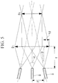
Fig. 5} Fig. 5 is a view showing, in outline, a case in which optical signals enter the lens of the transmission-side connector shown inFig. 4 , while being tilted by θ with respect to the optical axis. - {
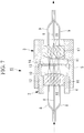
Fig. 6} Fig. 6 is a longitudinal sectional view showing an optical transmission connector device according to a second embodiment of the present invention. - {
Fig. 7} Fig. 7 is a longitudinal sectional view showing a modification of the optical transmission connector device shown inFig. 6 . - An optical
transmission connector device 1 according to a first embodiment of the present invention will be described below with reference to the drawings. - As shown in
Fig. 1 , the opticaltransmission connector device 1 of this embodiment is provided with a transmission-side connector 2 and a reception-side connector 3. - The transmission-
side connector 2 and the reception-side connector 3 are respectively provided with:housings housings optical fibers Fig. 2 , one end surfaces of which are fixed to thelenses 6 and 7 (only three optical fibers thereof are shown inFig. 1 ). Thelenses convex surfaces - The
convex surfaces lenses - The
housing 4 of the transmission-side connector 2 and thehousing 5 of the reception-side connector 3 are coupled to each other in a detachable manner. Thehousing 5 of the reception-side connector 3 is provided with afitting hole 12 into which thehousing 4 of the transmission-side connector 2 is fitted and is also provided with anabutting surface 13 against which thehousing 4 of the transmission-side connector 2 abuts in the longitudinal direction. Note that thehousings housings - Accordingly, when the
housings housing 4 of the transmission-side connector 2 abuts against theabutting surface 13 of thehousing 5 of the reception-side connector 3, thehousings Fig. 3 . Specifically, when the transmission-side connector 2 and the reception-side connector 3 are coupled, theconvex surface 10 of thelens 6 of the transmission-side connector 2 and theconvex surface 11 of thelens 7 of the reception-side connector 3 are disposed opposing each other with a predetermined gap therebetween, with the optical axes thereof aligned. - One ends of the
optical fibers lenses lenses optical fibers - In the transmission-
side connector 2, as shown inFig. 4 , the respectiveoptical fibers 8 are disposed such that the centers of the light beams emitted from one end surfaces of theoptical fibers 8 are made to intersect at one point (exit pupil) after being emitted from thelens 6. - Specifically, the
optical fibers 8 are disposed so as to satisfy the following conditional expression (1). - Specifically, when the maximum effective diameter of the
lens 6 of the transmission-side connector 2 is set to D1, and the maximum light-beam diameter at the position of the exit pupil of the light emitted from thelens 6 is set to D2, the conditional expression will be as follows.
- More specifically, in
Fig. 5 , the maximum light-beam diameter D2 is expressed by:
- From the above expression and expression (1), the following conditional expression (2) can be derived;

optical fibers 8, and f is the focal length of thelens 6. - Furthermore, the maximum effective diameter D1 is expressed by:

- Therefore, from the above expression and expression (2), the following conditional expression (3) can be derived;

optical fiber 8, and θ is a tilt angle of theoptical fiber 8. - In the reception-side connector 3, the respective
optical fibers 9 are disposed such that approximately parallel beams of light that have the centers of the light beams intersecting at one point (entrance pupil) outside theconvex surface 11 are converged when entering thelens 7 from theconvex surface 11 and are focused on one end surfaces of theoptical fibers 9. In this case, conditional expression (2) is also satisfied. In the figure,reference numeral 14 denotes a protective cover that protects thelens 6 of the transmission-side connector 2. - Then, the
housings side connector 2 and the reception-side connector 3 are coupled, thereby aligning the exit pupil of the transmission-side connector 2 and the entrance pupil of the reception-side connector 3. - The operation of the thus-configured optical
transmission connector device 1 of this embodiment will now be described. - In order to connect optical signals by using the optical
transmission connector device 1 of this embodiment, thehousing 4 of the transmission-side connector 2 and thehousing 5 of the reception-side connector 3 are coupled. Accordingly, the exit pupil of the transmission-side connector 2 and the entrance pupil of the reception-side connector 3 are aligned. - In this state, optical signals are guided via the
optical fibers 8 of the transmission-side connector 2. Although the optical signals guided inside theoptical fibers 8 spread when emitted from one end surfaces thereof, because the one end surfaces of theoptical fibers 8 are brought into close contact with thelens 6 with no gaps therebetween, in this embodiment, the light beams thereof propagate in thelens 6 without widely spreading and are focused by the power of theconvex surface 10 of thelens 6, thereby being converted into approximately parallel beams of light and being emitted. - The centers of the light beams of the plurality of optical signals, which are formed of the approximately parallel beams of light, emitted from the
lens 6 pass through one point at the exit pupil, then spread again, and enter theconvex surface 11 of thelens 7 of the reception-side connector 3. - The plurality of optical signals entering the
convex surface 11 of thelens 7 of the reception-side connector 3 are respectively focused by the power of theconvex surface 11 of thelens 7, thereby being made to separately enter one end surfaces of the plurality ofoptical fibers 9, which are fixed to thelens 7. - Accordingly, the optical signals guided via the plurality of
optical fibers 8 of the transmission-side connector 2 can be made to enter the plurality ofoptical fibers 9 of the reception-side connector 3, thus making it possible to easily connect the plurality of optical signals. - In this case, according to the optical
transmission connector device 1 of this embodiment, because the end surfaces of the respectiveoptical fibers 8 are brought into close contact with thelens 6, the light-beam diameters of the optical signals formed of approximately parallel beams of light emitted from thelens 6 can be sufficiently reduced. - In this way, according to the optical
transmission connector device 1 of this embodiment, there is an advantage that, even when a plurality of optical signals are connected, it is possible to use thesingle lenses lenses - The light emitted from the
lens 6 is formed into parallel beams of light, thereby making it possible to broaden the allowable range of error in the optical-axis direction. Specifically, there is an advantage that the degree of freedom in arrangement of the transmission-side connector 2 and the reception-side connector 3 is increased, and the tolerance to errors that occur at the time of assembly of the opticaltransmission connector device 1 is excellent. - When the optical
transmission connector device 1 is used in an endoscope system, there is an advantage that various scopes can be easily switched, connected to an image processing device, and cleaned after use and that, because thelens 6 is disposed at the distal ends of theoptical fibers 8 to expand the light-beam diameters of the optical signals so as to form them into approximately parallel beams of light, optical signals can be connected without reducing the transmission efficiency even if water stains and a foreign matter adhere to thelens 6. Furthermore, because theoptical fibers lenses - Note that, in the optical
transmission connector device 1 of this embodiment, although an example case in which the fiveoptical fibers optical fibers - Next, an optical
transmission connector device 15 according to a second embodiment of the present invention will be described below with reference to the drawings. - In the description of this embodiment, identical reference signs are assigned to components having configurations common to those in the optical
transmission connector device 1 of the above-described first embodiment, and a description thereof will be omitted. - As shown in
Fig. 6 , the opticaltransmission connector device 15 of this embodiment differs from the opticaltransmission connector device 1 of the first embodiment in thatlenses convex surfaces flat surfaces optical fibers flat surfaces lenses - According to the thus-configured optical
transmission connector device 15 of this embodiment, although optical signals guided by theoptical fibers 8 spread at large divergence angles when emitted from the one end surfaces of theoptical fibers 8, because the optical signals immediately enter theflat surface 18 of thelens 16, which is disposed opposing the one end surfaces of theoptical fibers 8 with minute gaps therebetween, the light-beam diameters of signal light beams, formed of approximately parallel beams of light, to be emitted from theconvex surface 10 of thelens 16 can be prevented from being increased much, and the above-described conditional expression (3) can be satisfied. - Specifically, according to this embodiment, there is also an advantage that it is possible to use the
single lenses lenses - Note that, in this embodiment, as in the optical
transmission connector device 1 of the first embodiment, it is also possible to adjust the tilts of the plurality ofoptical fibers 8 such that the centers of light beams of a plurality of signal light beams, formed of approximately parallel beams of light, emitted from thelens 16 intersect at one point, as shown inFig. 6 , or it is also possible to adjust the angles of the one end surfaces of theoptical fibers 8 with respect to the longitudinal axes thereof such that the centers of light beams of a plurality of signal light beams, formed of approximately parallel beams of light, emitted from thelens 16 intersect at one point, as shown inFig. 7 . -
- 1, 15 optical transmission connector device
- 2 transmission-side connector
- 3 reception-type connector
- 6, 7, 16, 17 lens (optical member)
- 8, 9 optical fiber
- 10, 11 convex surface
Claims (4)
- An optical transmission connector device comprising:a transmission-side connector that sends a plurality of optical signals; anda reception-side connector that receives the plurality of optical signals sent from the transmission-side connector,wherein the transmission-side connector and the reception-side connector each have: a plurality of optical fibers that transmit the optical signals; and an optical member that is disposed in contact with or in the vicinity of one end surfaces of the plurality of optical fibers;the optical member of the transmission-side connector is formed so as to convert the plurality of optical signals emitted from the one end surfaces of the optical fibers into approximately parallel beams of light and so as to cause the centers of light beams of the approximately parallel beams of light to intersect at approximately one point;the optical member of the reception-side connector is formed so as to cause the plurality of optical signals converted into approximately parallel beams of light at the optical member of the transmission-side connector to enter the separate optical fibers; andthe following conditional expression (1) is satisfied;where D1 is the maximum effective diameter of the optical member of the transmission-side connector, and D2 is the maximum light-beam diameter of the parallel light.

- An optical transmission connector device according to claim 1, wherein the following conditional expression (2) is satisfied;

- An optical transmission connector device according to claim 2, wherein the following conditional expression (3) is satisfied;

- An optical transmission connector device according to one of claims 1 to 3,
wherein the optical members each have a convex surface;
the convex surface has an aspheric surface shape in which power is weakened from the center toward the periphery thereof; and
the optical member of the reception-side connector and the optical member of the transmission-side connector are disposed with the convex surfaces thereof opposing each other.
Applications Claiming Priority (2)
| Application Number | Priority Date | Filing Date | Title |
|---|---|---|---|
| JP2014262879 | 2014-12-25 | ||
| PCT/JP2015/080717 WO2016103912A1 (en) | 2014-12-25 | 2015-10-30 | Optical transmission connector device |
Publications (2)
| Publication Number | Publication Date |
|---|---|
| EP3249433A1 true EP3249433A1 (en) | 2017-11-29 |
| EP3249433A4 EP3249433A4 (en) | 2018-10-24 |
Family
ID=56149947
Family Applications (1)
| Application Number | Title | Priority Date | Filing Date |
|---|---|---|---|
| EP15872481.5A Withdrawn EP3249433A4 (en) | 2014-12-25 | 2015-10-30 | Optical transmission connector device |
Country Status (5)
| Country | Link |
|---|---|
| US (1) | US9885840B2 (en) |
| EP (1) | EP3249433A4 (en) |
| JP (1) | JP6109427B2 (en) |
| CN (1) | CN107003481A (en) |
| WO (1) | WO2016103912A1 (en) |
Families Citing this family (2)
| Publication number | Priority date | Publication date | Assignee | Title |
|---|---|---|---|---|
| US11327250B1 (en) * | 2019-03-08 | 2022-05-10 | Wavefront Research, Inc. | Optical interconnect devices |
| WO2022079769A1 (en) * | 2020-10-12 | 2022-04-21 | オリンパス株式会社 | Waveguide connection structure, waveguide connector, waveguide unit, mode converter, imaging device, and endoscope |
Family Cites Families (22)
| Publication number | Priority date | Publication date | Assignee | Title |
|---|---|---|---|---|
| JPS56150714A (en) * | 1980-04-25 | 1981-11-21 | Nippon Telegr & Teleph Corp <Ntt> | Lens connector |
| JPS5984511U (en) * | 1983-10-27 | 1984-06-07 | 富士通株式会社 | Coupling structure of semiconductor laser and optical fiber |
| US7015454B2 (en) | 1998-10-22 | 2006-03-21 | Wavefront Research, Inc. | Relaxed tolerance optical interconnect system capable of providing an array of sub-images |
| US6635861B1 (en) | 1998-10-22 | 2003-10-21 | Wavefront Research, Inc. | Relaxed tolerance optical interconnect system having a GRIN rod lens |
| US7446298B1 (en) | 1998-10-22 | 2008-11-04 | Wavefront Research, Inc. | Relaxed tolerance optical interconnect systems |
| US6289152B1 (en) * | 1998-10-27 | 2001-09-11 | Adc Telecommunications, Inc. | Multiple port, fiber optic coupling device |
| US6438290B1 (en) * | 2000-06-22 | 2002-08-20 | Eastman Kodak Company | Micro-aspheric collimator lens |
| US20030081897A1 (en) | 2001-09-27 | 2003-05-01 | Nobuki Itoh | Aspherical rod lens and method of manufacturing aspherical rod lens |
| JP2003195012A (en) | 2001-09-27 | 2003-07-09 | Matsushita Electric Ind Co Ltd | Aspherical rod lens and method of manufacturing aspherical rod lens |
| WO2003107055A1 (en) | 2002-06-14 | 2003-12-24 | 日本板硝子株式会社 | Optical device unit, optical device, and microlens array |
| JP2004070311A (en) * | 2002-06-14 | 2004-03-04 | Nippon Sheet Glass Co Ltd | Optical device unit and optical device |
| CN101283491A (en) * | 2005-07-08 | 2008-10-08 | 晶体纤维公司 | Optocoupler device and method of making and using same |
| JP2007127797A (en) | 2005-11-02 | 2007-05-24 | Hitachi Cable Ltd | Optical module |
| JP2007178790A (en) | 2005-12-28 | 2007-07-12 | Sony Corp | Optical coupler and optical connector |
| US7660502B1 (en) * | 2006-07-12 | 2010-02-09 | Wavefront Research, Inc. | Optical interconnect and connector devices |
| CN102023340B (en) * | 2006-12-27 | 2013-10-16 | 日本电气硝子株式会社 | Lens assembly, optical device, optical axis adjusting method for an optical device |
| JP2008203546A (en) * | 2007-02-20 | 2008-09-04 | Hitachi Cable Ltd | Lens assembly and optical module using the same |
| US9557488B2 (en) * | 2011-01-11 | 2017-01-31 | Corning Incorporated | Optical connector with lenses having opposing angled planar surfaces |
| JP5747721B2 (en) | 2011-07-29 | 2015-07-15 | 富士通株式会社 | Optical transmission line, optical connector, and optical module |
| JP2013225010A (en) * | 2012-04-20 | 2013-10-31 | Sumitomo Electric Ind Ltd | Optical multiplexing/demultiplexing component |
| US9223091B2 (en) * | 2013-02-28 | 2015-12-29 | The United States Of America As Represented By The Secretary Of The Army | Light beam collimator particularly suitable for a densely packed array |
| US9645325B2 (en) * | 2015-05-01 | 2017-05-09 | Corning Optical Communications LLC | Expanded-beam ferrule with high coupling efficiency for optical interface devices |
-
2015
- 2015-10-30 JP JP2016543251A patent/JP6109427B2/en active Active
- 2015-10-30 WO PCT/JP2015/080717 patent/WO2016103912A1/en not_active Ceased
- 2015-10-30 EP EP15872481.5A patent/EP3249433A4/en not_active Withdrawn
- 2015-10-30 CN CN201580065854.0A patent/CN107003481A/en active Pending
-
2017
- 2017-06-22 US US15/630,656 patent/US9885840B2/en active Active
Also Published As
| Publication number | Publication date |
|---|---|
| JP6109427B2 (en) | 2017-04-05 |
| JPWO2016103912A1 (en) | 2017-04-27 |
| US9885840B2 (en) | 2018-02-06 |
| CN107003481A (en) | 2017-08-01 |
| US20170285278A1 (en) | 2017-10-05 |
| EP3249433A4 (en) | 2018-10-24 |
| WO2016103912A1 (en) | 2016-06-30 |
Similar Documents
| Publication | Publication Date | Title |
|---|---|---|
| US10718909B2 (en) | Expanded beam fiber optic connection system | |
| US8457458B2 (en) | Imaging interface for optical components | |
| US20150370012A1 (en) | Imaging apparatus | |
| US20090226137A1 (en) | Miniature mechanical transfer optical coupler | |
| US20170023747A1 (en) | Eye-safe interface for optical connector | |
| US20170160491A1 (en) | Eye-safe interface for optical connector | |
| EP1990665B1 (en) | System and apparatus for fiber optic connector | |
| EP2518549B1 (en) | Spatial multiplexer for coupling single-mode fibers to a multi-core fiber | |
| US12078854B2 (en) | Optical assembly | |
| US9885840B2 (en) | Optical transmission connector device | |
| WO2014151927A1 (en) | Universal fiber optic connector | |
| US9706906B2 (en) | Endoscope objective optical system | |
| CN105425344B (en) | A kind of optic fibre connector and connector | |
| JP2011164182A (en) | Optical connector connection body | |
| US20170017040A1 (en) | Collimating lens | |
| US20160223767A1 (en) | Optical fiber device | |
| EP4345518B1 (en) | Apparatus and method for low latency free-space optical communications | |
| JP2014052496A (en) | Optical connector between multi-core fibers | |
| US9304266B2 (en) | Optical communications module having an optical port that prevents relative movement from occurring between the optical port and a ferrule that is mated with the optical port | |
| US20190064444A1 (en) | Optical system for fiber optic termini | |
| KR101137229B1 (en) | Contactless optical fiber interconnecting apparatus | |
| WO2011083454A2 (en) | Optical data communication | |
| KR101507376B1 (en) | Expanded beam interconnects based on compound-lens | |
| TW201337370A (en) | Optical coupler | |
| JP2008116743A (en) | Multi-channel optical communication lens and optical module using the same |
Legal Events
| Date | Code | Title | Description |
|---|---|---|---|
| STAA | Information on the status of an ep patent application or granted ep patent |
Free format text: STATUS: THE INTERNATIONAL PUBLICATION HAS BEEN MADE |
|
| PUAI | Public reference made under article 153(3) epc to a published international application that has entered the european phase |
Free format text: ORIGINAL CODE: 0009012 |
|
| STAA | Information on the status of an ep patent application or granted ep patent |
Free format text: STATUS: REQUEST FOR EXAMINATION WAS MADE |
|
| 17P | Request for examination filed |
Effective date: 20170724 |
|
| AK | Designated contracting states |
Kind code of ref document: A1 Designated state(s): AL AT BE BG CH CY CZ DE DK EE ES FI FR GB GR HR HU IE IS IT LI LT LU LV MC MK MT NL NO PL PT RO RS SE SI SK SM TR |
|
| AX | Request for extension of the european patent |
Extension state: BA ME |
|
| DAV | Request for validation of the european patent (deleted) | ||
| DAX | Request for extension of the european patent (deleted) | ||
| A4 | Supplementary search report drawn up and despatched |
Effective date: 20180926 |
|
| RIC1 | Information provided on ipc code assigned before grant |
Ipc: G02B 6/32 20060101AFI20180920BHEP Ipc: G02B 23/26 20060101ALI20180920BHEP Ipc: G02B 6/26 20060101ALI20180920BHEP Ipc: G02B 6/40 20060101ALI20180920BHEP |
|
| STAA | Information on the status of an ep patent application or granted ep patent |
Free format text: STATUS: THE APPLICATION IS DEEMED TO BE WITHDRAWN |
|
| 18D | Application deemed to be withdrawn |
Effective date: 20190501 |