EP3249296A1 - Volatile organic compounds combustion device, boiler, tanker, and volatile organic compound combustion method - Google Patents
Volatile organic compounds combustion device, boiler, tanker, and volatile organic compound combustion method Download PDFInfo
- Publication number
- EP3249296A1 EP3249296A1 EP16755444.3A EP16755444A EP3249296A1 EP 3249296 A1 EP3249296 A1 EP 3249296A1 EP 16755444 A EP16755444 A EP 16755444A EP 3249296 A1 EP3249296 A1 EP 3249296A1
- Authority
- EP
- European Patent Office
- Prior art keywords
- voc
- volatile organic
- gas
- voc gas
- organic compound
- Prior art date
- Legal status (The legal status is an assumption and is not a legal conclusion. Google has not performed a legal analysis and makes no representation as to the accuracy of the status listed.)
- Granted
Links
Images



Classifications
-
- F—MECHANICAL ENGINEERING; LIGHTING; HEATING; WEAPONS; BLASTING
- F23—COMBUSTION APPARATUS; COMBUSTION PROCESSES
- F23G—CREMATION FURNACES; CONSUMING WASTE PRODUCTS BY COMBUSTION
- F23G7/00—Incinerators or other apparatus for consuming industrial waste, e.g. chemicals
- F23G7/06—Incinerators or other apparatus for consuming industrial waste, e.g. chemicals of waste gases or noxious gases, e.g. exhaust gases
- F23G7/061—Incinerators or other apparatus for consuming industrial waste, e.g. chemicals of waste gases or noxious gases, e.g. exhaust gases with supplementary heating
- F23G7/065—Incinerators or other apparatus for consuming industrial waste, e.g. chemicals of waste gases or noxious gases, e.g. exhaust gases with supplementary heating using gaseous or liquid fuel
-
- F—MECHANICAL ENGINEERING; LIGHTING; HEATING; WEAPONS; BLASTING
- F23—COMBUSTION APPARATUS; COMBUSTION PROCESSES
- F23G—CREMATION FURNACES; CONSUMING WASTE PRODUCTS BY COMBUSTION
- F23G7/00—Incinerators or other apparatus for consuming industrial waste, e.g. chemicals
- F23G7/06—Incinerators or other apparatus for consuming industrial waste, e.g. chemicals of waste gases or noxious gases, e.g. exhaust gases
-
- F—MECHANICAL ENGINEERING; LIGHTING; HEATING; WEAPONS; BLASTING
- F23—COMBUSTION APPARATUS; COMBUSTION PROCESSES
- F23G—CREMATION FURNACES; CONSUMING WASTE PRODUCTS BY COMBUSTION
- F23G7/00—Incinerators or other apparatus for consuming industrial waste, e.g. chemicals
-
- B—PERFORMING OPERATIONS; TRANSPORTING
- B63—SHIPS OR OTHER WATERBORNE VESSELS; RELATED EQUIPMENT
- B63B—SHIPS OR OTHER WATERBORNE VESSELS; EQUIPMENT FOR SHIPPING
- B63B35/00—Vessels or similar floating structures specially adapted for specific purposes and not otherwise provided for
- B63B35/44—Floating buildings, stores, drilling platforms, or workshops, e.g. carrying water-oil separating devices
- B63B2035/448—Floating hydrocarbon production vessels, e.g. Floating Production Storage and Offloading vessels [FPSO]
-
- B—PERFORMING OPERATIONS; TRANSPORTING
- B63—SHIPS OR OTHER WATERBORNE VESSELS; RELATED EQUIPMENT
- B63J—AUXILIARIES ON VESSELS
- B63J99/00—Subject matter not provided for in other groups of this subclass
- B63J2099/001—Burning of transported goods, e.g. fuel, boil-off or refuse
- B63J2099/003—Burning of transported goods, e.g. fuel, boil-off or refuse of cargo oil or fuel, or of boil-off gases, e.g. for propulsive purposes
-
- F—MECHANICAL ENGINEERING; LIGHTING; HEATING; WEAPONS; BLASTING
- F23—COMBUSTION APPARATUS; COMBUSTION PROCESSES
- F23G—CREMATION FURNACES; CONSUMING WASTE PRODUCTS BY COMBUSTION
- F23G2204/00—Supplementary heating arrangements
- F23G2204/10—Supplementary heating arrangements using auxiliary fuel
- F23G2204/103—Supplementary heating arrangements using auxiliary fuel gaseous or liquid fuel
-
- F—MECHANICAL ENGINEERING; LIGHTING; HEATING; WEAPONS; BLASTING
- F23—COMBUSTION APPARATUS; COMBUSTION PROCESSES
- F23G—CREMATION FURNACES; CONSUMING WASTE PRODUCTS BY COMBUSTION
- F23G2208/00—Safety aspects
- F23G2208/10—Preventing or abating fire or explosion, e.g. by purging
-
- F—MECHANICAL ENGINEERING; LIGHTING; HEATING; WEAPONS; BLASTING
- F23—COMBUSTION APPARATUS; COMBUSTION PROCESSES
- F23G—CREMATION FURNACES; CONSUMING WASTE PRODUCTS BY COMBUSTION
- F23G2209/00—Specific waste
- F23G2209/14—Gaseous waste or fumes
-
- Y—GENERAL TAGGING OF NEW TECHNOLOGICAL DEVELOPMENTS; GENERAL TAGGING OF CROSS-SECTIONAL TECHNOLOGIES SPANNING OVER SEVERAL SECTIONS OF THE IPC; TECHNICAL SUBJECTS COVERED BY FORMER USPC CROSS-REFERENCE ART COLLECTIONS [XRACs] AND DIGESTS
- Y02—TECHNOLOGIES OR APPLICATIONS FOR MITIGATION OR ADAPTATION AGAINST CLIMATE CHANGE
- Y02T—CLIMATE CHANGE MITIGATION TECHNOLOGIES RELATED TO TRANSPORTATION
- Y02T70/00—Maritime or waterways transport
- Y02T70/50—Measures to reduce greenhouse gas emissions related to the propulsion system
Definitions
- the present invention relates to a volatile organic compound combustion device which is used when treating volatile organic compounds, a boiler, a tanker, and a volatile organic compound combustion method.
- VOC volatile organic compounds
- PTL 1 discloses an engine system which is realized with a simple structure and at low cost even in a case where product gas which is obtained by reforming VOC is used as fuel gas.
- PTL 2 discloses an induction heating furnace having a furnace shell structure in which the airtightness of a furnace can be secured with a simple structure without increasing a size and there is no concern that electric discharge may occur.
- a furnace shell is disposed on the outside of a furnace shell surrounding a material to be heated, in a multilayered manner with a distance therebetween, inert gas is introduced into the space between the furnace shells, and the pressure of the inert gas is set to be higher than or equal to the pressure of atmosphere gas in the furnace shell surrounding a material to be heated.
- VOC As a method of treating VOC, there is a method of burning the VOC to incinerate it. In this case, the VOC is burned by using a dedicated burner which injects the VOC. However, it is necessary to prepare a dedicated compressor which pressurizes the VOC to a pressure sufficiently higher than the pressure in a furnace, and thus there is a problem in which the manufacturing cost of equipment for treating the VOC increases.
- the present invention has been made in view of such circumstances and an object thereof is to provide a volatile organic compound combustion device which reduces the manufacturing cost of equipment for burning volatile organic compounds, a boiler, a tanker, and a volatile organic compound combustion method.
- a volatile organic compound combustion device includes: a mixer which mixes VOC gas containing volatile organic compounds and combustion air; and a burner which burns fuel by using VOC mixed air mixed by the mixer.
- the VOC gas is premixed with the combustion air for burning fuel by the mixer, whereby the volatile organic compounds are burned by using the burner which burns the fuel.
- the pressure of the VOC gas higher than the pressure in a furnace or to pressurize the VOC gas to the same degree as the pressure of the fuel gas, and it is possible to make the pressure for pressurizing the VOC gas relatively low.
- the volatile organic compound combustion device further includes a wind box which supplies the VOC mixed air to the burner.
- the wind box includes an inner casing in which an atmosphere to which the combustion air and the VOC gas are injected is formed inside thereof, and an outer casing which surrounds the inner casing.
- the wind box in which the VOC mixed air in which the VOC gas and the combustion air are mixed is stored is made in a double casing structure, whereby it is possible to more reliably prevent leakage of the VOC mixed air in the wind box.
- the volatile organic compound combustion device further includes a purge gas supplying device which supplies purge gas to a space which is formed between the inner casing and the outer casing.
- the purge gas having a higher pressure than the inside of the inner casing is supplied to the space between the inner casing and the outer casing, whereby it is possible to more reliably prevent leakage of the VOC mixed air in the wind box.
- the purge gas is some of seal air produced for cooling a view port formed in a boiler main body forming a combustion chamber in which the fuel is burned.
- some of the seal air for cooling the view port is used as the purge gas which is supplied to the space between the inner casing and the outer casing, whereby the purge gas supplying device which supplies the purge gas to the space between the inner casing and the outer casing does not need to be provided separately from a seal air supplying device which supplies the seal air to the view port, and the volatile organic compound combustion device can be manufactured at low cost.
- the mixer is formed with: a combustion air outlet for injecting the combustion air; a plurality of VOC gas flow paths through which the VOC gas flows; and a plurality of VOC gas blowing-out nozzles corresponding to the plurality of VOC gas flow paths.
- the plurality of VOC gas blowing-out nozzles inject the VOC gas to a region to which the combustion air is injected.
- the VOC gas is distributed to the plurality of VOC gas flow paths and then injected from each VOC gas blowing-out nozzle, and therefore, it is possible to equally inject the VOC gas supplied to the mixer from the VOC gas blowing-out nozzles. Further, such a mixer can be formed on a relatively small scale and installed in a space-saving manner.
- the plurality of VOC gas flow paths are formed in such a manner that the longer the flow path length is, the larger the flow path cross-sectional area becomes.
- the volatile organic compound combustion device further includes a VOC gas blower which pressurizes the VOC gas to a pressure calculated based on a pressure of the combustion air and supplies the pressurized VOC gas to the mixer.
- the VOC gas has lower oxygen concentration than the combustion air and contains more inert gas than the combustion air.
- the VOC gas has lower oxygen concentration than the combustion air and contains more inert gas than the combustion air, whereby it is possible to lower a combustion temperature when the fuel burns, and it is possible to reduce the concentration of a nitrogen oxide (NOx) in flue gas which is generated due to combustion of the fuel.
- NOx nitrogen oxide
- the volatile organic compound combustion device further includes inert gas supply piping which supplies, as the inert gas, flue gas which is generated by burning the fuel by using the VOC mixed air to a heavy oil tank which stores heavy oil from which the volatile organic compounds volatilize.
- the flue gas which is generated due to combustion of the fuel is used as the inert gas, and therefore, it is possible to reduce the amount of fuel which is burned in order to produce the inert gas.
- a boiler according to a second aspect of the present invention includes the volatile organic compound combustion device according to the present invention.
- Such a boiler is provided with the volatile organic compound combustion device, and therefore, it is possible to burn the volatile organic compounds with equipment having a low manufacturing cost.
- a tanker includes: the volatile organic compound combustion device according to the present invention; and the heavy oil tank.
- Such a tanker is provided with the volatile organic compound combustion device according to the present invention, and therefore, it is possible to burn the volatile organic compounds volatilizing from the heavy oil tank with equipment having a low manufacturing cost.
- a volatile organic compound combustion method includes: a step of producing VOC mixed air by mixing VOC gas containing volatile organic compounds and combustion air; and a step of burning fuel by using the VOC mixed air.
- the VOC mixed air is produced by premixing the VOC gas with the combustion air for burning fuel, and the fuel is burned by using the VOC mixed air.
- the pressure of the VOC higher than the pressure in a furnace or to pressurize the VOC gas to the same degree as the pressure of the fuel gas, and it is possible to make the pressure for pressurizing the VOC gas relatively low.
- the volatile organic compound combustion device the boiler, the tanker, and the volatile organic compound combustion method according to the present invention, it is possible to reduce the manufacturing cost of equipment for burning the volatile organic compounds.
- a volatile organic compound combustion device 1 is installed in a tanker for transporting crude oil and equipment (FPSO: Floating Production, Storage and Offloading, or the like) for storing crude oil and is applied to a boiler provided together with a crude tank 2, as shown in Fig. 1 .
- crude oil is stored in a storage space formed inside thereof.
- Volatile organic compounds (VOC) having combustibility volatilize from the crude oil.
- the volatile organic compound combustion device 1 is provided with a VOC gas tank 5, a VOC gas blower 6, a boiler blower 7, and a mixer 8.
- the VOC gas tank 5 is connected to an upper portion of an area in which the crude oil is stored, of the storage space of the crude tank 2, through VOC gas piping 11 and stores VOC gas which is supplied from the crude tank 2.
- the VOC gas blower 6 pressurizes the VOC gas stored in the VOC gas tank 5 and supplies the VOC gas pressurized to a predetermined pressure (for example, 60 mbar) to the mixer 8.
- a predetermined pressure for example, 60 mbar
- the boiler blower 7 pressurizes air and supplies combustion air pressurized to a predetermined pressure (for example, 60 mbar) to the mixer 8.
- a predetermined pressure for example, 60 mbar
- the mixer 8 produces VOC mixed air by premixing the VOC gas supplied from the VOC gas blower 6 with the combustion air supplied from the boiler blower 7.
- the volatile organic compound combustion device 1 is provided with a wind box 14, a fuel gas supplying device 15, a boiler main body 16, and a burner 17.
- the wind box 14 temporarily stores the VOC mixed air premixed by the mixer 8, rectifies an air flow, and supplies it to the burner 17 at a constant flow rate.
- the fuel gas supplying device 15 supplies fuel gas (fuel) pressurized to a predetermined pressure (for example, 1 bar) to the burner 17.
- fuel gas gas of a hydrocarbon compound such as methane, ethane, or propane is exemplified.
- the boiler main body 16 is provided with a combustion chamber 18, and a flame is formed in the combustion chamber 18.
- the burner 17 burns the fuel gas supplied from the fuel gas supplying device 15 in the combustion chamber 18 by using the VOC mixed air supplied from the wind box 14.
- the boiler main body 16 is provided with a heat exchanger such as an evaporator (not shown).
- the heat exchanger produces high-temperature and high-pressure steam by heating water supplied from the outside to a steam drum 13 by using heat generated by combustion of the fuel gas.
- the steam produced by the heat exchanger is collected into the steam drum 13, and the steam separated in the steam drum 13 is supplied to an external demander (not shown).
- the boiler main body 16 further has a plurality of view ports (not shown) formed in a wall surface in order to view the state of the combustion chamber 18 of the inside from the outside of the boiler main body 16.
- the volatile organic compound combustion device 1 is further provided with inert gas supply piping 19 connected to an upper portion of the crude tank 2.
- the inert gas supply piping 19 supplies some or the whole of flue gas generated in the boiler main body 16 by the combustion of the fuel gas to the upper part of the storage space of the crude tank 2 as inert gas.
- the upstream side of the inert gas supply piping 19 is not shown. However, it is provided at an arbitrary position in a smoke furnace for the flue gas discharged from the boiler main body 16.
- the mixer 8 for mixing the VOC gas and the combustion air is shown.
- the mixer 8 is provided with a combustion air duct 21 and a VOC gas duct 22.
- the combustion air duct 21 is formed into a container formed in a rectangular parallelepiped shape and having the inside which is hollow, and a combustion air inlet 23 and a combustion air outlet 24 are formed therein.
- the combustion air inlet 23 is formed at the vertically upper end of the combustion air duct 21 and supplies the combustion air pressurized by the boiler blower 7 to the inside of the combustion air duct 21.
- the combustion air outlet 24 is formed by opening the entirety of the vertically lower surface of the combustion air duct 21 and sends the combustion air existing in the combustion air duct 21 vertically downward.
- the VOC gas duct 22 is formed in the shape of a container formed in a rectangular parallelepiped shape and having the inside which is hollow, and has a shape that is thinner and longer than the combustion air duct 21.
- the VOC gas duct 22 is disposed inside of the combustion air duct 21 in such a structure as to be inserted from the side of the combustion air duct 21. Most of the VOC gas duct 22 is installed over the entire longitudinal direction of the inside of the combustion air duct 21, and the remaining portion is exposed to the outside of the combustion air duct 21.
- a VOC gas inlet 25 a plurality of VOC gas blowing-out nozzles 26a, 26b, and 26c, and a plurality of VOC gas flow paths 27a, 27b, and 27c are formed.
- the number of VOC gas blowing-out nozzles and the number of VOC gas flow paths are not limited to three as in this embodiment and may be two or may be four or more.
- the VOC gas inlet 25 is formed at the vertically upper end of the portion which is disposed outside the combustion air duct 21, of the VOC gas duct 22.
- the VOC gas inlet 25 divergingly supplies the VOC gas which is supplied from the VOC gas blower 6, to the plurality of VOC gas flow paths 27a, 27b, and 27c.
- the respective VOC gas blowing-out nozzles 26a, 26b, and 26c are disposed side by side on a straight line along a longitudinal direction on the lower surface of the VOC gas duct 22.
- Each of the VOC gas blowing-out nozzles 26a, 26b, and 26c is provided at the same height position as the vertically lower end of the combustion air duct 21. Therefore, each of the VOC gas blowing-out nozzles 26a, 26b, and 26c is disposed so as to be surrounded by the combustion air outlet 24 of the combustion air duct 21.
- Each of the VOC gas blowing-out nozzles 26a, 26b, and 26c is formed into a tapered shape in which the flow path area decreases toward the tip, and is made such that the flow path cross-sectional area decreases toward the downstream side in a flow direction in which the VOC gas flows and the VOC gas is accelerated and ejected vertically downward.
- the plurality of VOC gas flow paths 27a, 27b, and 27c are formed inside of the VOC gas duct 22 and correspond on a one-to-one basis to the plurality of VOC gas blowing-out nozzles 26a, 26b, and 26c. Therefore, the first VOC gas blowing-out nozzle 26a is connected to the downstream end of the first VOC gas flow path 27a, the second VOC gas blowing-out nozzle 26b is connected to the downstream end of the second VOC gas flow path 27b, and the third VOC gas blowing-out nozzle 26c is connected to the downstream end of the third VOC gas flow path 27c. In this manner, each of the VOC gas flow paths 27a, 27b, and 27c is an independent flow path.
- Each of the VOC gas flow paths 27a, 27b, and 27c extends in the longitudinal direction of the VOC gas duct 22, the second VOC gas flow path 27b is located below the first VOC gas flow path 27a, and the third VOC gas flow path 27c is located below the second VOC gas flow path 27b. Therefore, the first VOC gas flow path 27a is formed such that the flow path bypasses the second VOC gas flow path 27b from the vertically upper side, and therefore, the flow path length of the first VOC gas flow path 27a is longer than that of the second VOC gas flow path 27b.
- the second VOC gas flow path 27b is formed such that the flow path bypasses the third VOC gas flow path 27c from the vertically upper side, and therefore, the flow path length of the second VOC gas flow path 27b is longer than that of the third VOC gas flow path 27c. Accordingly, the first VOC gas blowing-out nozzle 26a is located at the position farthest from the VOC gas inlet 25, and the third VOC gas blowing-out nozzle 26c is located at the position closest to the VOC gas inlet 25.
- the VOC gas flow paths 27a, 27b, and 27c are formed in such a manner that the longer the flow path length is, the larger the flow path cross-sectional area becomes. That is, the VOC gas flow paths 27a, 27b, and 27c are formed such that the flow path cross-sectional area of the VOC gas flow path which is connected to the VOC gas blowing-out nozzle which is farther from the VOC gas inlet 25 in the horizontal direction, among the VOC gas blowing-out nozzles 26a, 26b, and 26c, becomes larger.
- the first VOC gas flow path 27a corresponding to the first VOC gas blowing-out nozzle 26a farthest from the VOC gas inlet 25 in the horizontal direction has a flow path cross-sectional area larger than that of the second VOC gas flow path 27b corresponding to the next second VOC gas blowing-out nozzle 26b
- the third VOC gas flow path 27c corresponding to the third VOC gas blowing-out nozzle 26c closest to the VOC gas inlet 25 in the horizontal direction has a flow path cross-sectional area smaller than that of the next second VOC gas flow path 27b.
- the flow path cross-sectional area is adjusted according to the distance in the horizontal direction from the VOC gas inlet 25 to each of the VOC gas blowing-out nozzles 26a, 26b, and 26c, and the flow path cross-sectional area is adjusted in this manner, so that a pressure loss when the VOC gas flows through each of the VOC gas flow paths 27a, 27b, and 27c from the VOC gas inlet 25 to each of the VOC gas blowing-out nozzles 26a, 26b, 26c is equalized.
- the wind box 14 is shown.
- the wind box 14 is provided with an inner casing 31 and an outer casing 32.
- an inner space 33 to which the VOC mixed air obtained by mixing the VOC gas and the combustion air is supplied from the mixer 8 is formed inside thereof.
- the outer casing 32 is made to be a container surrounding the inner casing 31 and forms an outer space 34 between itself and the inner casing 31.
- Purge gas is supplied from a purge gas supplying device 35 to the outer space 34.
- the purge gas air or nitrogen gas is exemplified.
- the volatile organic compound combustion device 1 is provided with a seal gas supplying device (not shown).
- the seal gas supplying device pressurizes air and blows seal air pressurized to a predetermined pressure (for example, 200 mbar) to a plurality of view ports (not shown) formed in the boiler main body 16, thereby cooling each view port.
- Some of the seal air pressurized by the seal gas supplying device is supplied to the purge gas supplying device 35 as purge gas.
- the burner 17 is disposed in the inner space 33 of the wind box 14, and the tip side (the lower end side) forming a flame is exposed to the combustion chamber 18 of the boiler main body 16.
- a bottom view of the burner 17 is shown.
- the burner 17 is provided with a burner outer cylinder 41 and a plurality of fuel gas nozzles 42 to which fuel gas is supplied.
- the burner outer cylinder 41 is formed in a cylindrical shape.
- the plurality of fuel gas nozzles 42 are respectively formed in a tubular shape and are disposed inside of the burner outer cylinder 41 side by side along a concentric circle centered on the central axis of the burner outer cylinder 41.
- the space between the burner outer cylinder 41 and each of the fuel gas nozzles 42 serves as a VOC mixed air nozzle 46 through which the VOC mixed air flows. Therefore, the VOC mixed air flows so as to surround the fuel gas which is ejected from each of the fuel gas nozzles 42.
- an open portion or an opening portion which allows the flow of the VOC mixed air in the inner space 33 is provided in the burner outer cylinder 41. In this way, as shown by arrows in Fig. 4 , the VOC mixed air flows into the inside of the burner outer cylinder 41 and is led to the VOC mixed air nozzle 46.
- each of the fuel gas nozzles 42 is connected to a fuel gas header 44 to which the fuel gas is led, and the fuel gas is distributed from the fuel gas header 44 to each of the fuel gas nozzles 42. Further, the space between the fuel gas nozzles 42 serves as a VOC mixed air flow path 45 through which the VOC mixed air flows. The VOC mixed air flowing through the VOC mixed air flow path 45 is led to the VOC mixed air nozzle 46.
- the burner 17 injects the fuel gas from each fuel gas nozzle 42 and injects the VOC mixed gas from the periphery of each fuel gas nozzle 42 by the VOC mixed air nozzle 46, whereby the fuel gas and the VOC mixed air are diffused from the outlet of the burner 17 to form a single flame such that the flame falls within a furnace and are burned in the combustion chamber 18.
- the combustion air is supplied from the boiler blower 7 to the mixer 8 at a predetermined pressure, and the VOC gas is supplied from the VOC gas blower 6 to the mixer 8 at a pressure calculated based on the pressure of the combustion air.
- the pressure of the VOC gas is set to be a pressure equal to the pressure of the combustion air or a pressure slightly higher than the pressure of the combustion air.
- the combustion air supplied to the mixer 8 is supplied to the inner space 33 of the wind box 14 through the combustion air outlet 24 of the mixer 8.
- the plurality of VOC gas flow paths 27a, 27b, and 27c are formed in such a manner that the longer the flow path length is, the larger the flow path cross-sectional area becomes.
- an increase in pressure loss in each of the VOC gas flow paths 27a, 27b, and 27c, which supply the VOC gas to the VOC gas blowing-out nozzles 26a, 26b, and 26c farther from the VOC gas inlet 25 in the horizontal direction, is reduced.
- the VOC gas supplied to the mixer 8 is equally supplied to the plurality of VOC gas blowing-out nozzles 26a, 26b, and 26c without a decrease in the flow rate of the VOC gas which is supplied to the VOC gas blowing-out nozzles 26a, 26b, and 26c farther from the VOC gas inlet 25.
- the VOC gas is accelerated and blown out from the plurality of VOC gas blowing-out nozzles 26a, 26b, and 26c and is favorably mixed with the combustion air supplied through the combustion air outlet 24, to be supplied to the inner space 33 of the wind box 14.
- the VOC gas is equally supplied to each of the VOC gas blowing-out nozzles 26a, 26b, and 26c and injected therefrom, and therefore, the concentration of the volatile organic compound in the VOC gas which is injected from the respective VOC gas blowing-out nozzles 26a, 26b, and 26c can be equalized.
- the flow path cross-sectional area of each of the plurality of VOC gas flow paths 27a, 27b, and 27c is appropriately formed, whereby the combustion air which is supplied from the boiler blower 7 and the VOC gas which is supplied from the VOC gas blower 6 can be appropriately mixed with a small pressure loss.
- the mixer 8 is formed in this manner, whereby it can be formed on a small scale and installed in a space-saving manner.
- the VOC mixed air mixed by the mixer 8 fills the inner space 33 of the wind box 14 and is supplied to the burner 17 at a predetermined flow rate to be injected into the combustion chamber 18 of the boiler main body 16 through the VOC mixed air nozzle 46 of the burner 17.
- Fuel gas is further supplied from the fuel gas supplying device 15 to the burner 17 at a predetermined pressure.
- the fuel gas supplied from the fuel gas supplying device 15 to the burner 17 is injected into the combustion chamber 18 of the boiler main body 16 through the plurality of fuel gas nozzles 42 of the burner 17.
- the fuel gas injected from each fuel gas nozzle 42 is burned by using oxygen contained in the VOC mixed air injected from the VOC mixed air nozzle 46 and forms a flame.
- the volatile organic compounds contained in the VOC mixed air are burned using the oxygen contained in the VOC mixed air by the flame caused by the combustion of the fuel gas.
- the flue gas generated by combustion of the fuel gas and the volatile organic compounds is partially supplied to the upper portion of the storage space of the crude tank 2 through the inert gas supply piping 19 (refer to Fig. 1 ) as an inert gas.
- the inert gas supplied to the crude tank 2 is mixed with the gas filled in the upper portion of the storage space of the crude tank 2 to reduce the oxygen concentration of the gas filled in the upper portion of the storage space of the crude tank 2.
- the volatile organic compound volatilizing from the crude oil stored in the crude tank 2 is prevented from igniting due to a reduction in the oxygen concentration of the gas filled in the upper portion of the storage space of the crude tank 2.
- the volatile organic compound volatilizing from the crude oil is mixed with the inert gas which is supplied to the crude tank 2 through the inert gas supply piping 19 and becomes VOC gas.
- the VOC gas stored in the upper portion of the crude tank 2 is supplied to the VOC gas tank 5 through the VOC gas piping 11 and stored in the VOC gas tank 5.
- the VOC gas which is supplied to the mixer 8 contains the volatile organic compounds volatilizing from the crude oil, and the flue gas generated by combustion.
- Nitrogen contained in the combustion air or the fuel gas produces a nitrogen oxide (NOx) by reacting with oxygen when the fuel gas is burned at a high temperature by using the combustion air.
- the VOC mixed air which is used for the combustion of the fuel gas in the combustion chamber 18 has higher inert gas concentration than the combustion air which is supplied from the boiler blower 7 to the mixer 8, because the VOC gas contains the flue gas. Heat which is generated by the combustion of the fuel gas is also used for heating of the inert gas, whereby a temperature is lowered and the NOx which is produced is reduced.
- a through-hole is formed in the inner casing 31 of the wind box 14 in a case where due to breakage, a through-hole is formed in the inner casing 31 of the wind box 14, a through-hole is formed in a mounting portion where the inner casing 31 and the mixer 8 are joined to each other, or a through-hole is formed in a mounting portion where the inner casing 31 and the boiler main body 16 are joined to each other.
- the purge gas which is supplied to the outer space 34 of the wind box 14 flows from the outer space 34 of the wind box 14 to the inner space 33 through the formed through-hole.
- the VOC mixed air existing in the inner space 33 of the wind box 14 is more reliably prevented from leaking to the outside of the wind box 14, compared to another wind box which is not provided with the outer casing 32.
- the volatile organic compound combustion device 1 can be manufactured by remodeling an existing boiler.
- the existing boiler is provided with the boiler blower 7, a wind box which is provided with only the inner casing 31, the fuel gas supplying device 15, the boiler main body 16, and the burner 17.
- the volatile organic compound combustion device 1 can be easily manufactured by forming the wind box 14 by adding the outer casing 32 to the inner casing 31, and adding the VOC gas tank 5, the VOC gas blower 6, the mixer 8, and the purge gas supplying device 35 to the existing boiler.
- FIG. 7 shows a burner with which a volatile organic compound combustion device of a first comparative example is provided.
- a burner 101 has a VOC gas nozzle 102 added to the burner 17 in the embodiment described above.
- the VOC gas nozzle 102 is formed in a tubular shape and is disposed separately from the plurality of fuel gas nozzles 42 inside of the burner outer cylinder 41.
- the VOC gas needs be pressurized to a pressure higher than the pressure in the combustion chamber 18 that is inside of a furnace, that is, to a pressure approximately equal to the pressure of the fuel gas which is injected from the plurality of fuel gas nozzles 42, and thus the volatile organic compound combustion device of the first comparative example needs to be provided with a dedicated compressor for pressurizing the VOC gas to a pressure approximately equal to the pressure of the fuel gas which is injected from the fuel gas nozzle 42.
- the combustion air is mixed with the VOC gas, whereby it is possible to secure a pressure for injecting the VOC gas into the combustion chamber 18, even if a small-scale VOC gas blower 6 having a pressure ratio lower than that in a dedicated compressor which pressurizes the VOC gas to a pressure approximately equal to the pressure of the fuel gas which is injected from the fuel gas nozzle 42 is used. For this reason, in the volatile organic compound combustion device 1, such a dedicated compressor does not need to be provided, and thus the manufacturing cost can be reduced.
- the burner 17 of this embodiment does not need to be provided with the VOC gas nozzle 102 as in the first comparative example, and therefore, it can be more easily manufactured and the manufacturing cost can be further reduced.
- the plurality of fuel gas nozzles 42 of the burner 17 inject VOC mixed fuel in which the fuel gas and the VOC gas are mixed, thereby burning the volatile organic compounds.
- VOC mixed fuel in which the fuel gas and the VOC gas are mixed, thereby burning the volatile organic compounds.
- a modification example of the volatile organic compound combustion device is shown.
- the installation place of the mixer 8 in the wind box 14 is different from that in the embodiment described above, and others are formed in the same manner as in the embodiment described above.
- the mixer 8 and the wind box 14 are disposed so as to be aligned in the horizontal direction, and the mixer 8 is laterally installed such that the combustion air inlet 23 is horizontally aligned with the combustion air outlet 24.
- the mixer 8 is installed such that the combustion air supplied from the boiler blower 7 and the VOC gas supplied from the VOC gas blower 6 are injected in parallel in the horizontal direction, rather than vertically downward, into the inner space 33 of the wind box 14.
- the burner 17 burns the fuel gas by using the VOC mixed air mixed by the mixer 8, whereby it is possible to burn low-pressure VOC gas.
- the VOC gas blower 6 which is formed on a smaller scale than a compressor which pressurizes the VOC gas to a pressure equivalent to the pressure of the fuel gas can be used.
- the installation location of the mixer 8 is not limited to the vertically upper side or the lateral side of the wind box 14, and the mixer 8 may be installed at any position as long as it is an installation location where the combustion air supplied from the boiler blower 7 and the VOC gas supplied from the VOC gas blower 6 can be supplied to the inner space 33 of the wind box 14.
- the mixer 8 can be replaced by another mixer which mixes VOC gas with combustion air.
- a mixer which mixes VOC gas with combustion air by using a baffle plate is exemplified.
- a dedicated compressor for pressurizing VOC gas does not need to be provided, and thus equipment for burning volatile organic compounds can be easily manufactured at low cost by using a small-scale VOC gas blower 6.
- the mixer 8 of this embodiment the plurality of VOC gas blowing-out nozzles 26a, 26b, and 26c and the plurality of VOC gas flow paths 27a, 27b, and 27c are formed, whereby a pressure loss when the combustion air and the VOC gas are mixed can be reduced compared to the mixer using a baffle plate, and the mixer 8 can be formed on a small scale and installed in a space-saving manner. For this reason, in the volatile organic compound combustion device 1, the mixer 8 can be easily added to an existing boiler, compared to a volatile organic compound combustion device which is provided with the mixer using a baffle plate.
- the seal air which is supplied to the plurality of view ports formed in the boiler main body 16 being used as the purge gas which is supplied to the outer space 34 between the inner casing 31 and the outer casing 32 of the wind box 14 is an example, and purge gas different from the seal air may be supplied to the outer space 34.
- purge gas compressed air compressed by a compressor which is provided separately from the seal gas supplying device, for example, compressed air for instrumentation is exemplified.
- the purge gas supplying device 35 can be omitted.
- the wind box 14 does not need to be formed in a double casing structure, and the wind box 14 can be formed such that the inner space 33 that is an atmosphere into which the combustion air and the VOC gas are injected and the outside of the wind box 14 are separated by a single layer.
- a volatile organic compound combustion device with such a wind box applied thereto also does not need to be provided with a dedicated compressor for pressurizing the VOC gas, similar to the volatile organic compound combustion device 1 described above, and thus equipment for burning volatile organic compounds can be easily manufactured at low cost by using a small-scale VOC gas blower 6.
- the volatile organic compound combustion device 1 can also be applied to a boiler provided together with a crude tank which is not mounted on a tanker. As such a crude tank, a tank which is disposed on the ground is exemplified.
- the crude oil can be replaced by substances other than crude oil from which volatile organic compounds volatilize.
- substances chemical products such as an adhesive and a paint are exemplified.
- a volatile organic compound combustion device which is applied to such a case also does not need to be provided with a dedicated compressor for pressurizing the VOC gas, similar to the volatile organic compound combustion device 1 in the embodiment described above, and thus equipment for burning volatile organic compounds can be easily manufactured at low cost by using a small-scale VOC gas blower 6.
Landscapes
- Engineering & Computer Science (AREA)
- Environmental & Geological Engineering (AREA)
- Mechanical Engineering (AREA)
- General Engineering & Computer Science (AREA)
- Incineration Of Waste (AREA)
- Gasification And Melting Of Waste (AREA)
Abstract
Description
- The present invention relates to a volatile organic compound combustion device which is used when treating volatile organic compounds, a boiler, a tanker, and a volatile organic compound combustion method.
- The emission of volatile organic compounds (VOC) to an environment is regulated, and thus it is necessary to reduce the VOC which is emitted to the environment.
- PTL 1 discloses an engine system which is realized with a simple structure and at low cost even in a case where product gas which is obtained by reforming VOC is used as fuel gas.
-
PTL 2 discloses an induction heating furnace having a furnace shell structure in which the airtightness of a furnace can be secured with a simple structure without increasing a size and there is no concern that electric discharge may occur. In this induction heating furnace, a furnace shell is disposed on the outside of a furnace shell surrounding a material to be heated, in a multilayered manner with a distance therebetween, inert gas is introduced into the space between the furnace shells, and the pressure of the inert gas is set to be higher than or equal to the pressure of atmosphere gas in the furnace shell surrounding a material to be heated. -
- [PTL 1] Japanese Unexamined Patent Application Publication No.
2010-203364 - [PTL 2] Japanese Patent No.
5162949 - On the other hand, as a method of treating VOC, there is a method of burning the VOC to incinerate it. In this case, the VOC is burned by using a dedicated burner which injects the VOC. However, it is necessary to prepare a dedicated compressor which pressurizes the VOC to a pressure sufficiently higher than the pressure in a furnace, and thus there is a problem in which the manufacturing cost of equipment for treating the VOC increases.
- The present invention has been made in view of such circumstances and an object thereof is to provide a volatile organic compound combustion device which reduces the manufacturing cost of equipment for burning volatile organic compounds, a boiler, a tanker, and a volatile organic compound combustion method.
- A volatile organic compound combustion device according to a first aspect of the present invention includes: a mixer which mixes VOC gas containing volatile organic compounds and combustion air; and a burner which burns fuel by using VOC mixed air mixed by the mixer.
- When burning volatile organic compounds by using a dedicated burner which injects only VOC gas, it is necessary to prepare a dedicated compressor which pressurizes the VOC gas to a pressure sufficiently higher than the pressure in a furnace. Further, for example, even in a case of burning volatile organic compounds with a burner by mixing VOC gas with fuel which is regarded as a fuel gas, it is necessary to prepare a dedicated compressor which pressurizes the VOC gas to the same degree as the pressure of the fuel gas.
- Therefore, in the volatile organic compound combustion device according to the first aspect of the present invention, the VOC gas is premixed with the combustion air for burning fuel by the mixer, whereby the volatile organic compounds are burned by using the burner which burns the fuel. In this manner, it is only necessary to mix the VOC gas with the combustion air, and therefore, it is not necessary to make the pressure of the VOC gas higher than the pressure in a furnace or to pressurize the VOC gas to the same degree as the pressure of the fuel gas, and it is possible to make the pressure for pressurizing the VOC gas relatively low. In this way, it is possible to burn the volatile organic compounds by pressurizing the VOC gas by using a VOC gas blower or the like having a smaller scale and a lower pressure ratio than a compressor, and it is possible to reduce the manufacturing cost.
- The volatile organic compound combustion device according to the first aspect of the present invention further includes a wind box which supplies the VOC mixed air to the burner. The wind box includes an inner casing in which an atmosphere to which the combustion air and the VOC gas are injected is formed inside thereof, and an outer casing which surrounds the inner casing.
- In such a volatile organic compound combustion device, the wind box in which the VOC mixed air in which the VOC gas and the combustion air are mixed is stored is made in a double casing structure, whereby it is possible to more reliably prevent leakage of the VOC mixed air in the wind box.
- The volatile organic compound combustion device according to the first aspect of the present invention further includes a purge gas supplying device which supplies purge gas to a space which is formed between the inner casing and the outer casing.
- In such a volatile organic compound combustion device, the purge gas having a higher pressure than the inside of the inner casing is supplied to the space between the inner casing and the outer casing, whereby it is possible to more reliably prevent leakage of the VOC mixed air in the wind box.
- The purge gas is some of seal air produced for cooling a view port formed in a boiler main body forming a combustion chamber in which the fuel is burned.
- In such a volatile organic compound combustion device, some of the seal air for cooling the view port is used as the purge gas which is supplied to the space between the inner casing and the outer casing, whereby the purge gas supplying device which supplies the purge gas to the space between the inner casing and the outer casing does not need to be provided separately from a seal air supplying device which supplies the seal air to the view port, and the volatile organic compound combustion device can be manufactured at low cost.
- The mixer is formed with: a combustion air outlet for injecting the combustion air; a plurality of VOC gas flow paths through which the VOC gas flows; and a plurality of VOC gas blowing-out nozzles corresponding to the plurality of VOC gas flow paths. The plurality of VOC gas blowing-out nozzles inject the VOC gas to a region to which the combustion air is injected.
- In the mixer of such a volatile organic compound combustion device, the VOC gas is distributed to the plurality of VOC gas flow paths and then injected from each VOC gas blowing-out nozzle, and therefore, it is possible to equally inject the VOC gas supplied to the mixer from the VOC gas blowing-out nozzles. Further, such a mixer can be formed on a relatively small scale and installed in a space-saving manner.
- The plurality of VOC gas flow paths are formed in such a manner that the longer the flow path length is, the larger the flow path cross-sectional area becomes.
- Even in a case where the distances from a VOC gas inlet to which the VOC gas is supplied to the plurality of VOC gas blowing-out nozzles in the mixer are different from each other, by forming the plurality of VOC gas flow paths in such a manner that the longer the flow path length is, the larger the flow path cross-sectional area becomes, it is possible to uniformly inject the VOC gas from the plurality of VOC gas blowing-out nozzles, and it is possible to properly mix the VOC gas and the combustion air such that the concentration of the volatile organic compound in the VOC mixed air is not biased.
- The volatile organic compound combustion device according to the first aspect of the present invention further includes a VOC gas blower which pressurizes the VOC gas to a pressure calculated based on a pressure of the combustion air and supplies the pressurized VOC gas to the mixer.
- In such a volatile organic compound combustion device, since it is sufficient if the VOC gas is pressurized to the pressure calculated based on the pressure of the combustion air and mixed with the combustion air, a blower having a pressure ratio lower than that in a compressor can be used. In this way, it is possible to reduce an installation cost and an operating cost.
- The VOC gas has lower oxygen concentration than the combustion air and contains more inert gas than the combustion air.
- The VOC gas has lower oxygen concentration than the combustion air and contains more inert gas than the combustion air, whereby it is possible to lower a combustion temperature when the fuel burns, and it is possible to reduce the concentration of a nitrogen oxide (NOx) in flue gas which is generated due to combustion of the fuel.
- The volatile organic compound combustion device according to the first aspect of the present invention further includes inert gas supply piping which supplies, as the inert gas, flue gas which is generated by burning the fuel by using the VOC mixed air to a heavy oil tank which stores heavy oil from which the volatile organic compounds volatilize.
- In such a volatile organic compound combustion device, as the inert gas which is supplied to the heavy oil tank, the flue gas which is generated due to combustion of the fuel is used. In this manner, the flue gas which is generated due to combustion of the volatile organic compounds can also be used as the inert gas, and therefore, it is possible to reduce the amount of fuel which is burned in order to produce the inert gas.
- A boiler according to a second aspect of the present invention includes the volatile organic compound combustion device according to the present invention.
- Such a boiler is provided with the volatile organic compound combustion device, and therefore, it is possible to burn the volatile organic compounds with equipment having a low manufacturing cost.
- A tanker according to a third aspect of the present invention includes: the volatile organic compound combustion device according to the present invention; and the heavy oil tank.
- Such a tanker is provided with the volatile organic compound combustion device according to the present invention, and therefore, it is possible to burn the volatile organic compounds volatilizing from the heavy oil tank with equipment having a low manufacturing cost.
- A volatile organic compound combustion method according to a fourth aspect of the present invention includes: a step of producing VOC mixed air by mixing VOC gas containing volatile organic compounds and combustion air; and a step of burning fuel by using the VOC mixed air.
- When burning volatile organic compounds by using a dedicated burner which injects only VOC gas, it is necessary to prepare a dedicated compressor which pressurizes the VOC gas to a pressure sufficiently higher than the pressure in a furnace. Further, for example, even in a case of burning volatile organic compounds with a burner by mixing VOC gas with fuel which is regarded as a fuel gas, it is necessary to prepare a dedicated compressor which pressurizes the VOC gas to the same degree as the pressure of the fuel gas.
- Therefore, according to the volatile organic compound combustion method of the fourth aspect of the present invention, the VOC mixed air is produced by premixing the VOC gas with the combustion air for burning fuel, and the fuel is burned by using the VOC mixed air. In this manner, it is only necessary to mix the VOC with the combustion air, and therefore, it is not necessary to make the pressure of the VOC higher than the pressure in a furnace or to pressurize the VOC gas to the same degree as the pressure of the fuel gas, and it is possible to make the pressure for pressurizing the VOC gas relatively low. In this way, it is possible to easily burn the volatile organic compounds by using a blower or the like having a smaller scale and a lower pressure ratio than a compressor. Advantageous Effects of Invention
- According to the volatile organic compound combustion device, the boiler, the tanker, and the volatile organic compound combustion method according to the present invention, it is possible to reduce the manufacturing cost of equipment for burning the volatile organic compounds.
-
-
Fig. 1 is a conceptual diagram showing a volatile organic compound combustion device according to an embodiment of the present invention. -
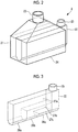
Fig. 2 is a perspective view showing a mixer of the volatile organic compound combustion device. -
Fig. 3 is a perspective view showing a VOC duct of the mixer. -
Fig. 4 is a side view showing a wind box of the volatile organic compound combustion device. -
Fig. 5 is a bottom view showing a burner of the volatile organic compound combustion device. -
Fig. 6 is a schematic diagram showing the burner ofFig. 5 . -
Fig. 7 is a plan view showing a burner of a first comparative example. -
Fig. 8 is a schematic diagram showing a modification example of the volatile organic compound combustion device. Description of Embodiments - Hereinafter, a volatile organic compound combustion device according to an embodiment of the present invention will be described with reference to the drawings.
- A volatile organic compound combustion device 1 is installed in a tanker for transporting crude oil and equipment (FPSO: Floating Production, Storage and Offloading, or the like) for storing crude oil and is applied to a boiler provided together with a
crude tank 2, as shown inFig. 1 . In thecrude tank 2, crude oil is stored in a storage space formed inside thereof. Volatile organic compounds (VOC) having combustibility volatilize from the crude oil. - The volatile organic compound combustion device 1 is provided with a
VOC gas tank 5, aVOC gas blower 6, aboiler blower 7, and amixer 8. - The
VOC gas tank 5 is connected to an upper portion of an area in which the crude oil is stored, of the storage space of thecrude tank 2, throughVOC gas piping 11 and stores VOC gas which is supplied from thecrude tank 2. - The
VOC gas blower 6 pressurizes the VOC gas stored in theVOC gas tank 5 and supplies the VOC gas pressurized to a predetermined pressure (for example, 60 mbar) to themixer 8. - The
boiler blower 7 pressurizes air and supplies combustion air pressurized to a predetermined pressure (for example, 60 mbar) to themixer 8. - The
mixer 8 produces VOC mixed air by premixing the VOC gas supplied from theVOC gas blower 6 with the combustion air supplied from theboiler blower 7. - The volatile organic compound combustion device 1 is provided with a
wind box 14, a fuelgas supplying device 15, a boilermain body 16, and aburner 17. - The
wind box 14 temporarily stores the VOC mixed air premixed by themixer 8, rectifies an air flow, and supplies it to theburner 17 at a constant flow rate. - The fuel
gas supplying device 15 supplies fuel gas (fuel) pressurized to a predetermined pressure (for example, 1 bar) to theburner 17. As the fuel gas, gas of a hydrocarbon compound such as methane, ethane, or propane is exemplified. - The boiler
main body 16 is provided with acombustion chamber 18, and a flame is formed in thecombustion chamber 18. - The
burner 17 burns the fuel gas supplied from the fuelgas supplying device 15 in thecombustion chamber 18 by using the VOC mixed air supplied from thewind box 14. - The boiler
main body 16 is provided with a heat exchanger such as an evaporator (not shown). The heat exchanger produces high-temperature and high-pressure steam by heating water supplied from the outside to asteam drum 13 by using heat generated by combustion of the fuel gas. The steam produced by the heat exchanger is collected into thesteam drum 13, and the steam separated in thesteam drum 13 is supplied to an external demander (not shown). The boilermain body 16 further has a plurality of view ports (not shown) formed in a wall surface in order to view the state of thecombustion chamber 18 of the inside from the outside of the boilermain body 16. - The volatile organic compound combustion device 1 is further provided with inert gas supply piping 19 connected to an upper portion of the
crude tank 2. The inert gas supply piping 19 supplies some or the whole of flue gas generated in the boilermain body 16 by the combustion of the fuel gas to the upper part of the storage space of thecrude tank 2 as inert gas. InFig. 1 , the upstream side of the inertgas supply piping 19 is not shown. However, it is provided at an arbitrary position in a smoke furnace for the flue gas discharged from the boilermain body 16. - In
Fig. 2 , themixer 8 for mixing the VOC gas and the combustion air is shown. Themixer 8 is provided with acombustion air duct 21 and aVOC gas duct 22. Thecombustion air duct 21 is formed into a container formed in a rectangular parallelepiped shape and having the inside which is hollow, and acombustion air inlet 23 and acombustion air outlet 24 are formed therein. Thecombustion air inlet 23 is formed at the vertically upper end of thecombustion air duct 21 and supplies the combustion air pressurized by theboiler blower 7 to the inside of thecombustion air duct 21. Thecombustion air outlet 24 is formed by opening the entirety of the vertically lower surface of thecombustion air duct 21 and sends the combustion air existing in thecombustion air duct 21 vertically downward. - The
VOC gas duct 22 is formed in the shape of a container formed in a rectangular parallelepiped shape and having the inside which is hollow, and has a shape that is thinner and longer than thecombustion air duct 21. TheVOC gas duct 22 is disposed inside of thecombustion air duct 21 in such a structure as to be inserted from the side of thecombustion air duct 21. Most of theVOC gas duct 22 is installed over the entire longitudinal direction of the inside of thecombustion air duct 21, and the remaining portion is exposed to the outside of thecombustion air duct 21. - In the
VOC gas duct 22, as shown inFig. 3 , aVOC gas inlet 25, a plurality of VOC gas blowing-outnozzles gas flow paths - The
VOC gas inlet 25 is formed at the vertically upper end of the portion which is disposed outside thecombustion air duct 21, of theVOC gas duct 22. TheVOC gas inlet 25 divergingly supplies the VOC gas which is supplied from theVOC gas blower 6, to the plurality of VOCgas flow paths - The respective VOC gas blowing-out
nozzles VOC gas duct 22. Each of the VOC gas blowing-outnozzles combustion air duct 21. Therefore, each of the VOC gas blowing-outnozzles combustion air outlet 24 of thecombustion air duct 21. - Each of the VOC gas blowing-out
nozzles - The plurality of VOC
gas flow paths VOC gas duct 22 and correspond on a one-to-one basis to the plurality of VOC gas blowing-outnozzles nozzle 26a is connected to the downstream end of the first VOCgas flow path 27a, the second VOC gas blowing-outnozzle 26b is connected to the downstream end of the second VOCgas flow path 27b, and the third VOC gas blowing-outnozzle 26c is connected to the downstream end of the third VOCgas flow path 27c. In this manner, each of the VOCgas flow paths - Each of the VOC
gas flow paths VOC gas duct 22, the second VOCgas flow path 27b is located below the first VOCgas flow path 27a, and the third VOCgas flow path 27c is located below the second VOCgas flow path 27b. Therefore, the first VOCgas flow path 27a is formed such that the flow path bypasses the second VOCgas flow path 27b from the vertically upper side, and therefore, the flow path length of the first VOCgas flow path 27a is longer than that of the second VOCgas flow path 27b. Similarly, the second VOCgas flow path 27b is formed such that the flow path bypasses the third VOCgas flow path 27c from the vertically upper side, and therefore, the flow path length of the second VOCgas flow path 27b is longer than that of the third VOCgas flow path 27c. Accordingly, the first VOC gas blowing-outnozzle 26a is located at the position farthest from theVOC gas inlet 25, and the third VOC gas blowing-outnozzle 26c is located at the position closest to theVOC gas inlet 25. - Then, the VOC
gas flow paths gas flow paths VOC gas inlet 25 in the horizontal direction, among the VOC gas blowing-outnozzles gas flow path 27a corresponding to the first VOC gas blowing-outnozzle 26a farthest from theVOC gas inlet 25 in the horizontal direction has a flow path cross-sectional area larger than that of the second VOCgas flow path 27b corresponding to the next second VOC gas blowing-outnozzle 26b, and the third VOCgas flow path 27c corresponding to the third VOC gas blowing-outnozzle 26c closest to theVOC gas inlet 25 in the horizontal direction has a flow path cross-sectional area smaller than that of the next second VOCgas flow path 27b. That is, in the VOCgas flow paths VOC gas inlet 25 to each of the VOC gas blowing-outnozzles gas flow paths VOC gas inlet 25 to each of the VOC gas blowing-outnozzles - In
Fig. 4 , thewind box 14 is shown. Thewind box 14 is provided with aninner casing 31 and anouter casing 32. In theinner casing 31, aninner space 33 to which the VOC mixed air obtained by mixing the VOC gas and the combustion air is supplied from themixer 8 is formed inside thereof. Theouter casing 32 is made to be a container surrounding theinner casing 31 and forms anouter space 34 between itself and theinner casing 31. Purge gas is supplied from a purgegas supplying device 35 to theouter space 34. As the purge gas, air or nitrogen gas is exemplified. - The volatile organic compound combustion device 1 is provided with a seal gas supplying device (not shown). The seal gas supplying device pressurizes air and blows seal air pressurized to a predetermined pressure (for example, 200 mbar) to a plurality of view ports (not shown) formed in the boiler
main body 16, thereby cooling each view port. - Some of the seal air pressurized by the seal gas supplying device is supplied to the purge
gas supplying device 35 as purge gas. - The
burner 17 is disposed in theinner space 33 of thewind box 14, and the tip side (the lower end side) forming a flame is exposed to thecombustion chamber 18 of the boilermain body 16. - In
Fig. 5 , a bottom view of theburner 17 is shown. Theburner 17 is provided with a burnerouter cylinder 41 and a plurality offuel gas nozzles 42 to which fuel gas is supplied. - The burner
outer cylinder 41 is formed in a cylindrical shape. The plurality offuel gas nozzles 42 are respectively formed in a tubular shape and are disposed inside of the burnerouter cylinder 41 side by side along a concentric circle centered on the central axis of the burnerouter cylinder 41. - The space between the burner
outer cylinder 41 and each of thefuel gas nozzles 42 serves as a VOCmixed air nozzle 46 through which the VOC mixed air flows. Therefore, the VOC mixed air flows so as to surround the fuel gas which is ejected from each of thefuel gas nozzles 42. - In the burner
outer cylinder 41, an open portion or an opening portion which allows the flow of the VOC mixed air in theinner space 33 is provided. In this way, as shown by arrows inFig. 4 , the VOC mixed air flows into the inside of the burnerouter cylinder 41 and is led to the VOCmixed air nozzle 46. - In
Fig. 6 , the flow of the fuel gas flowing through theburner 17 is indicated by arrows. That is, each of thefuel gas nozzles 42 is connected to afuel gas header 44 to which the fuel gas is led, and the fuel gas is distributed from thefuel gas header 44 to each of thefuel gas nozzles 42. Further, the space between thefuel gas nozzles 42 serves as a VOC mixedair flow path 45 through which the VOC mixed air flows. The VOC mixed air flowing through the VOC mixedair flow path 45 is led to the VOCmixed air nozzle 46. - In this manner, the
burner 17 injects the fuel gas from eachfuel gas nozzle 42 and injects the VOC mixed gas from the periphery of eachfuel gas nozzle 42 by the VOCmixed air nozzle 46, whereby the fuel gas and the VOC mixed air are diffused from the outlet of theburner 17 to form a single flame such that the flame falls within a furnace and are burned in thecombustion chamber 18. - Subsequently, an operation of the volatile organic compound combustion device 1 will be described.
- The combustion air is supplied from the
boiler blower 7 to themixer 8 at a predetermined pressure, and the VOC gas is supplied from theVOC gas blower 6 to themixer 8 at a pressure calculated based on the pressure of the combustion air. The pressure of the VOC gas is set to be a pressure equal to the pressure of the combustion air or a pressure slightly higher than the pressure of the combustion air. The combustion air supplied to themixer 8 is supplied to theinner space 33 of thewind box 14 through thecombustion air outlet 24 of themixer 8. - In the
mixer 8, the plurality of VOCgas flow paths gas flow paths nozzles VOC gas inlet 25 in the horizontal direction, is reduced. For this reason, the VOC gas supplied to themixer 8 is equally supplied to the plurality of VOC gas blowing-outnozzles nozzles VOC gas inlet 25. - The VOC gas is accelerated and blown out from the plurality of VOC gas blowing-out
nozzles combustion air outlet 24, to be supplied to theinner space 33 of thewind box 14. - In this manner, in the
mixer 8, the VOC gas is equally supplied to each of the VOC gas blowing-outnozzles nozzles - Further, in the
mixer 8, the flow path cross-sectional area of each of the plurality of VOCgas flow paths boiler blower 7 and the VOC gas which is supplied from theVOC gas blower 6 can be appropriately mixed with a small pressure loss. Further, themixer 8 is formed in this manner, whereby it can be formed on a small scale and installed in a space-saving manner. - The VOC mixed air mixed by the
mixer 8 fills theinner space 33 of thewind box 14 and is supplied to theburner 17 at a predetermined flow rate to be injected into thecombustion chamber 18 of the boilermain body 16 through the VOCmixed air nozzle 46 of theburner 17. Fuel gas is further supplied from the fuelgas supplying device 15 to theburner 17 at a predetermined pressure. The fuel gas supplied from the fuelgas supplying device 15 to theburner 17 is injected into thecombustion chamber 18 of the boilermain body 16 through the plurality offuel gas nozzles 42 of theburner 17. The fuel gas injected from eachfuel gas nozzle 42 is burned by using oxygen contained in the VOC mixed air injected from the VOCmixed air nozzle 46 and forms a flame. At this time, the volatile organic compounds contained in the VOC mixed air are burned using the oxygen contained in the VOC mixed air by the flame caused by the combustion of the fuel gas. - The flue gas generated by combustion of the fuel gas and the volatile organic compounds is partially supplied to the upper portion of the storage space of the
crude tank 2 through the inert gas supply piping 19 (refer toFig. 1 ) as an inert gas. The inert gas supplied to thecrude tank 2 is mixed with the gas filled in the upper portion of the storage space of thecrude tank 2 to reduce the oxygen concentration of the gas filled in the upper portion of the storage space of thecrude tank 2. The volatile organic compound volatilizing from the crude oil stored in thecrude tank 2 is prevented from igniting due to a reduction in the oxygen concentration of the gas filled in the upper portion of the storage space of thecrude tank 2. The volatile organic compound volatilizing from the crude oil is mixed with the inert gas which is supplied to thecrude tank 2 through the inertgas supply piping 19 and becomes VOC gas. - The VOC gas stored in the upper portion of the
crude tank 2 is supplied to theVOC gas tank 5 through theVOC gas piping 11 and stored in theVOC gas tank 5. In this manner, the VOC gas which is supplied to themixer 8 contains the volatile organic compounds volatilizing from the crude oil, and the flue gas generated by combustion. - Nitrogen contained in the combustion air or the fuel gas produces a nitrogen oxide (NOx) by reacting with oxygen when the fuel gas is burned at a high temperature by using the combustion air. The VOC mixed air which is used for the combustion of the fuel gas in the
combustion chamber 18 has higher inert gas concentration than the combustion air which is supplied from theboiler blower 7 to themixer 8, because the VOC gas contains the flue gas. Heat which is generated by the combustion of the fuel gas is also used for heating of the inert gas, whereby a temperature is lowered and the NOx which is produced is reduced. - In the
wind box 14, there is a case where due to breakage, a through-hole is formed in theinner casing 31 of thewind box 14, a through-hole is formed in a mounting portion where theinner casing 31 and themixer 8 are joined to each other, or a through-hole is formed in a mounting portion where theinner casing 31 and the boilermain body 16 are joined to each other. In a case where such a through-hole is formed, the purge gas which is supplied to theouter space 34 of thewind box 14 flows from theouter space 34 of thewind box 14 to theinner space 33 through the formed through-hole. Due to the purge gas which is supplied to theouter space 34 flowing into theinner space 33, the VOC mixed air existing in theinner space 33 of thewind box 14 is more reliably prevented from leaking to the outside of thewind box 14, compared to another wind box which is not provided with theouter casing 32. - The volatile organic compound combustion device 1 can be manufactured by remodeling an existing boiler. For example, the existing boiler is provided with the
boiler blower 7, a wind box which is provided with only theinner casing 31, the fuelgas supplying device 15, the boilermain body 16, and theburner 17. The volatile organic compound combustion device 1 can be easily manufactured by forming thewind box 14 by adding theouter casing 32 to theinner casing 31, and adding theVOC gas tank 5, theVOC gas blower 6, themixer 8, and the purgegas supplying device 35 to the existing boiler. -
Fig. 7 shows a burner with which a volatile organic compound combustion device of a first comparative example is provided. Aburner 101 has aVOC gas nozzle 102 added to theburner 17 in the embodiment described above. TheVOC gas nozzle 102 is formed in a tubular shape and is disposed separately from the plurality offuel gas nozzles 42 inside of the burnerouter cylinder 41. - When the
burner 101 injects the VOC gas into thecombustion chamber 18 through theVOC gas nozzle 102, the VOC gas needs be pressurized to a pressure higher than the pressure in thecombustion chamber 18 that is inside of a furnace, that is, to a pressure approximately equal to the pressure of the fuel gas which is injected from the plurality offuel gas nozzles 42, and thus the volatile organic compound combustion device of the first comparative example needs to be provided with a dedicated compressor for pressurizing the VOC gas to a pressure approximately equal to the pressure of the fuel gas which is injected from thefuel gas nozzle 42. - In contrast, in the volatile organic compound combustion device 1 of this embodiment, the combustion air is mixed with the VOC gas, whereby it is possible to secure a pressure for injecting the VOC gas into the
combustion chamber 18, even if a small-scaleVOC gas blower 6 having a pressure ratio lower than that in a dedicated compressor which pressurizes the VOC gas to a pressure approximately equal to the pressure of the fuel gas which is injected from thefuel gas nozzle 42 is used. For this reason, in the volatile organic compound combustion device 1, such a dedicated compressor does not need to be provided, and thus the manufacturing cost can be reduced. - Further, the
burner 17 of this embodiment does not need to be provided with theVOC gas nozzle 102 as in the first comparative example, and therefore, it can be more easily manufactured and the manufacturing cost can be further reduced. - In a volatile organic compound combustion device of a second comparative example, the plurality of
fuel gas nozzles 42 of theburner 17 inject VOC mixed fuel in which the fuel gas and the VOC gas are mixed, thereby burning the volatile organic compounds. At this time, in the volatile organic compound combustion device of the second comparative example, when mixing the fuel gas and the VOC gas with the VOC mixed fuel, it is necessary to pressurize the VOC gas to a pressure approximately equal to the pressure of the fuel gas which is injected from the plurality offuel gas nozzles 42, and thus, similar to the volatile organic compound combustion device of the first comparative example, a compressor for pressurizing the VOC gas to a pressure approximately equal to the pressure of the fuel gas which is injected from the plurality offuel gas nozzles 42 needs to be provided. - In
Fig. 8 , a modification example of the volatile organic compound combustion device is shown. In a volatile organiccompound combustion device 51 of the modification example, the installation place of themixer 8 in thewind box 14 is different from that in the embodiment described above, and others are formed in the same manner as in the embodiment described above. In the volatile organiccompound combustion device 51, themixer 8 and thewind box 14 are disposed so as to be aligned in the horizontal direction, and themixer 8 is laterally installed such that thecombustion air inlet 23 is horizontally aligned with thecombustion air outlet 24. At this time, themixer 8 is installed such that the combustion air supplied from theboiler blower 7 and the VOC gas supplied from theVOC gas blower 6 are injected in parallel in the horizontal direction, rather than vertically downward, into theinner space 33 of thewind box 14. - In the volatile organic
compound combustion device 51, similar to the volatile organic compound combustion device 1 described above, theburner 17 burns the fuel gas by using the VOC mixed air mixed by themixer 8, whereby it is possible to burn low-pressure VOC gas. For this reason, in the volatile organiccompound combustion device 51, as a device for pressurizing the VOC gas, theVOC gas blower 6 which is formed on a smaller scale than a compressor which pressurizes the VOC gas to a pressure equivalent to the pressure of the fuel gas can be used. - The installation location of the
mixer 8 is not limited to the vertically upper side or the lateral side of thewind box 14, and themixer 8 may be installed at any position as long as it is an installation location where the combustion air supplied from theboiler blower 7 and the VOC gas supplied from theVOC gas blower 6 can be supplied to theinner space 33 of thewind box 14. - The
mixer 8 can be replaced by another mixer which mixes VOC gas with combustion air. As such a mixer, a mixer which mixes VOC gas with combustion air by using a baffle plate is exemplified. Also in a volatile organic compound combustion device which is provided with such a mixer, similar to the volatile organic compound combustion device 1 described above, a dedicated compressor for pressurizing VOC gas does not need to be provided, and thus equipment for burning volatile organic compounds can be easily manufactured at low cost by using a small-scaleVOC gas blower 6. Further, in themixer 8 of this embodiment, the plurality of VOC gas blowing-outnozzles gas flow paths mixer 8 can be formed on a small scale and installed in a space-saving manner. For this reason, in the volatile organic compound combustion device 1, themixer 8 can be easily added to an existing boiler, compared to a volatile organic compound combustion device which is provided with the mixer using a baffle plate. - The seal air which is supplied to the plurality of view ports formed in the boiler
main body 16 being used as the purge gas which is supplied to theouter space 34 between theinner casing 31 and theouter casing 32 of thewind box 14 is an example, and purge gas different from the seal air may be supplied to theouter space 34. As such purge gas, compressed air compressed by a compressor which is provided separately from the seal gas supplying device, for example, compressed air for instrumentation is exemplified. - In a case where the
wind box 14 can sufficiently prevent the leakage of the VOC gas without supplying the purge gas to theouter space 34, the purgegas supplying device 35 can be omitted. Further, in a case where it is possible to sufficiently prevent breakage which causes the leakage of the VOC gas, thewind box 14 does not need to be formed in a double casing structure, and thewind box 14 can be formed such that theinner space 33 that is an atmosphere into which the combustion air and the VOC gas are injected and the outside of thewind box 14 are separated by a single layer. A volatile organic compound combustion device with such a wind box applied thereto also does not need to be provided with a dedicated compressor for pressurizing the VOC gas, similar to the volatile organic compound combustion device 1 described above, and thus equipment for burning volatile organic compounds can be easily manufactured at low cost by using a small-scaleVOC gas blower 6. - The volatile organic compound combustion device 1 can also be applied to a boiler provided together with a crude tank which is not mounted on a tanker. As such a crude tank, a tank which is disposed on the ground is exemplified.
- Further, the crude oil can be replaced by substances other than crude oil from which volatile organic compounds volatilize. As such substances, chemical products such as an adhesive and a paint are exemplified. A volatile organic compound combustion device which is applied to such a case also does not need to be provided with a dedicated compressor for pressurizing the VOC gas, similar to the volatile organic compound combustion device 1 in the embodiment described above, and thus equipment for burning volatile organic compounds can be easily manufactured at low cost by using a small-scale
VOC gas blower 6. -
- 1:
- volatile organic compound combustion device
- 2:
- crude tank
- 5:
- VOC gas tank
- 6:
- VOC gas blower
- 7:
- boiler blower
- 8:
- mixer
- 11:
- VOC gas piping
- 14:
- wind box
- 16:
- boiler main body
- 17:
- burner
- 18:
- combustion chamber
- 19:
- inert gas supply piping
- 24:
- combustion air outlet
- 25:
- VOC gas inlet
- 26a, 26b, 26c:
- VOC gas blowing-out nozzle
- 27a, 27b, 27c:
- VOC gas flow path
- 31:
- inner casing
- 32:
- outer casing
- 33:
- inner space
- 34:
- outer space
- 35:
- purge gas supplying device
Claims (12)
- A volatile organic compound combustion device comprising:a mixer which mixes VOC gas containing volatile organic compounds and combustion air; anda burner which burns fuel by using VOC mixed air mixed by the mixer.
- The volatile organic compound combustion device according to Claim 1, further comprising:a wind box which supplies the VOC mixed air to the burner,wherein the wind box includesan inner casing in which an atmosphere to which the combustion air and the VOC gas are injected is formed inside thereof, andan outer casing which surrounds the inner casing.
- The volatile organic compound combustion device according to Claim 2, further comprising:a purge gas supplying device which supplies purge gas to a space which is formed between the inner casing and the outer casing.
- The volatile organic compound combustion device according to Claim 3, wherein the purge gas is some of seal air produced for cooling a view port formed in a boiler main body forming a combustion chamber in which the fuel is burned.
- The volatile organic compound combustion device according to any one of Claims 1 to 4, wherein the mixer is formed with:a combustion air outlet for injecting the combustion air;a plurality of VOC gas flow paths through which the VOC gas flows; anda plurality of VOC gas blowing-out nozzles corresponding to the plurality of VOC gas flow paths, andthe plurality of VOC gas blowing-out nozzles inject the VOC gas to a region to which the combustion air is injected.
- The volatile organic compound combustion device according to Claim 5, wherein the plurality of VOC gas flow paths are formed in such a manner that the longer the flow path length is, the larger the flow path cross-sectional area becomes.
- The volatile organic compound combustion device according to any one of Claims 1 to 6, further comprising:a VOC gas blower which pressurizes the VOC gas to a pressure calculated based on a pressure of the combustion air and supplies the pressurized VOC gas to the mixer.
- The volatile organic compound combustion device according to any one of Claims 1 to 7, wherein the VOC gas has lower oxygen concentration than the combustion air and contains more inert gas than the combustion air.
- The volatile organic compound combustion device according to Claim 8, further comprising:inert gas supply piping which supplies, as the inert gas, flue gas which is generated by burning the fuel by using the VOC mixed air to a heavy oil tank which stores heavy oil from which the volatile organic compounds volatilize.
- A boiler comprising: the volatile organic compound combustion device according to any one of Claims 1 to 9.
- A tanker comprising: the volatile organic compound combustion device according to any one of Claims 1 to 9.
- A volatile organic compound combustion method comprising:a step of producing VOC mixed air by mixing VOC gas containing volatile organic compounds and combustion air; anda step of burning fuel by using the VOC mixed air.
Applications Claiming Priority (2)
| Application Number | Priority Date | Filing Date | Title |
|---|---|---|---|
| JP2015038285A JP6580341B2 (en) | 2015-02-27 | 2015-02-27 | Volatile organic compound combustion apparatus, boiler, tanker, and volatile organic compound combustion method |
| PCT/JP2016/055148 WO2016136699A1 (en) | 2015-02-27 | 2016-02-23 | Volatile organic compounds combustion device, boiler, tanker, and volatile organic compound combustion method |
Publications (3)
| Publication Number | Publication Date |
|---|---|
| EP3249296A1 true EP3249296A1 (en) | 2017-11-29 |
| EP3249296A4 EP3249296A4 (en) | 2018-01-31 |
| EP3249296B1 EP3249296B1 (en) | 2019-09-04 |
Family
ID=56788674
Family Applications (1)
| Application Number | Title | Priority Date | Filing Date |
|---|---|---|---|
| EP16755444.3A Active EP3249296B1 (en) | 2015-02-27 | 2016-02-23 | Volatile organic compounds combustion device, boiler, tanker, and volatile organic compound combustion method |
Country Status (6)
| Country | Link |
|---|---|
| EP (1) | EP3249296B1 (en) |
| JP (1) | JP6580341B2 (en) |
| KR (1) | KR102048133B1 (en) |
| CN (1) | CN107250670B (en) |
| DK (1) | DK3249296T3 (en) |
| WO (1) | WO2016136699A1 (en) |
Families Citing this family (4)
| Publication number | Priority date | Publication date | Assignee | Title |
|---|---|---|---|---|
| KR101839847B1 (en) * | 2017-08-25 | 2018-03-19 | 단국대학교 산학협력단 | Apparatus for combusting volatile organic compounds |
| JP7152957B2 (en) * | 2019-01-08 | 2022-10-13 | 三菱重工マリンマシナリ株式会社 | Marine boiler and modification method of marine boiler |
| KR102142995B1 (en) * | 2019-07-26 | 2020-08-12 | 대우조선해양 주식회사 | Fuel Gas Supply System and Method for Crude Oil Eco-carrier |
| CN110671708A (en) * | 2019-09-24 | 2020-01-10 | 南通亚泰工程技术有限公司 | A Versatile Inert Gas System for Handling VOCs |
Family Cites Families (22)
| Publication number | Priority date | Publication date | Assignee | Title |
|---|---|---|---|---|
| JPS48630U (en) * | 1971-04-14 | 1973-01-08 | ||
| JPS5162949A (en) | 1974-11-30 | 1976-05-31 | Mitsubishi Heavy Ind Ltd | DEJITARU KANSUHATSUSEIKI |
| JPS63119698U (en) * | 1987-01-29 | 1988-08-02 | ||
| US5215018A (en) * | 1990-06-26 | 1993-06-01 | White Horse Technologies, Inc. | Pollution control apparatus and method for pollution control |
| NO305853B1 (en) * | 1997-01-29 | 1999-08-09 | Norske Stats Oljeselskap | Procedure for reducing emissions of volatile organic compounds |
| JP2002303403A (en) * | 2001-04-03 | 2002-10-18 | Oji Paper Co Ltd | Method and apparatus for sealing boiler penetration, and airport cleaner |
| JP4041690B2 (en) * | 2002-04-12 | 2008-01-30 | 大日本印刷株式会社 | Organic component-containing gas, waste liquid treatment method and treatment apparatus |
| CN2586893Y (en) * | 2002-11-21 | 2003-11-19 | 亚泰金属工业股份有限公司 | Energy-saving waste-gas burning apparatus |
| JP2005246321A (en) * | 2004-03-05 | 2005-09-15 | Mitsubishi Electric Corp | Gas processing apparatus and gas processing method |
| FR2881209B1 (en) * | 2005-01-21 | 2015-04-24 | Snecma Moteurs | GAS INCINERATOR INSTALLED ON A LIQUEFIED GAS TRANSPORT VESSEL |
| CN101218471A (en) * | 2005-07-04 | 2008-07-09 | 三浦工业株式会社 | boiler |
| JP2007283182A (en) * | 2006-04-14 | 2007-11-01 | Fujimori Kogyo Co Ltd | Apparatus and method for treating volatile organic compounds |
| JP2008281237A (en) * | 2007-05-08 | 2008-11-20 | Kyokuto Kaihatsu Kogyo Co Ltd | Deodorizing mechanism of waste disposal equipment |
| KR100780231B1 (en) * | 2007-05-09 | 2007-11-27 | 주식회사 대우엔지니어링 | Combustion device of volatile organic compound |
| JP4947594B2 (en) * | 2007-09-06 | 2012-06-06 | Jx日鉱日石エネルギー株式会社 | Pier equipment and hydrocarbon recovery system |
| JP5054051B2 (en) | 2009-03-04 | 2012-10-24 | 三井造船株式会社 | Engine system |
| GB2471909C (en) * | 2009-07-18 | 2019-02-13 | Hamworthy Combustion Engineering Ltd | Incinerator for boil-off gas |
| GB201001525D0 (en) * | 2010-01-29 | 2010-03-17 | Hamworthy Combustion Eng Ltd | Improvements in or relating to heating |
| JP5135369B2 (en) * | 2010-03-15 | 2013-02-06 | 株式会社東芝 | Sludge drying method |
| CN102913918B (en) * | 2011-08-01 | 2015-06-17 | 中国石油化工股份有限公司 | Catalytic combustion processing method of high-concentration organic exhaust gas |
| WO2013162965A1 (en) * | 2012-04-27 | 2013-10-31 | John Zink Company, Llc | Handling liquid hydrocarbon |
| JP5398881B2 (en) * | 2012-07-11 | 2014-01-29 | 月島環境エンジニアリング株式会社 | VOC-containing gas processing apparatus and processing method |
-
2015
- 2015-02-27 JP JP2015038285A patent/JP6580341B2/en active Active
-
2016
- 2016-02-23 WO PCT/JP2016/055148 patent/WO2016136699A1/en not_active Ceased
- 2016-02-23 CN CN201680010775.4A patent/CN107250670B/en active Active
- 2016-02-23 KR KR1020177023215A patent/KR102048133B1/en active Active
- 2016-02-23 EP EP16755444.3A patent/EP3249296B1/en active Active
- 2016-02-23 DK DK16755444.3T patent/DK3249296T3/en active
Also Published As
| Publication number | Publication date |
|---|---|
| CN107250670A (en) | 2017-10-13 |
| KR102048133B1 (en) | 2019-11-22 |
| CN107250670B (en) | 2020-06-16 |
| JP2016161171A (en) | 2016-09-05 |
| WO2016136699A1 (en) | 2016-09-01 |
| KR20170107022A (en) | 2017-09-22 |
| JP6580341B2 (en) | 2019-09-25 |
| EP3249296B1 (en) | 2019-09-04 |
| EP3249296A4 (en) | 2018-01-31 |
| DK3249296T3 (en) | 2019-10-14 |
Similar Documents
| Publication | Publication Date | Title |
|---|---|---|
| US9388976B2 (en) | High pressure combustor with hot surface ignition | |
| US8033254B2 (en) | Submerged combustion vaporizer with low NOx | |
| CN105318353B (en) | Gas turbine burner | |
| EP3249296B1 (en) | Volatile organic compounds combustion device, boiler, tanker, and volatile organic compound combustion method | |
| KR20070119566A (en) | Koanda gas burner device and combustion method | |
| CN101956988B (en) | Incinerator for boil-off gas | |
| CN108474553B (en) | Staged steam injection system | |
| FI57922B (en) | FOERFARANDE OCH ANORDNING FOER FRAMSTAELLNING AV SVAVELDIOXID | |
| KR102410184B1 (en) | Low steam consumption and high smoke-free capacity waste gas flare | |
| CN103307611A (en) | Device for disposing harmful gases | |
| US8016590B2 (en) | Combustion burner resulting in low oxides of nitrogen | |
| CN108884997A (en) | burner | |
| TW202118728A (en) | High-temperature oxygen generator and high-temperature oxygen generation method | |
| KR102537965B1 (en) | Arraratus for premixing combustion air and fuel gas | |
| US20210025589A1 (en) | Staged gas injection system | |
| RU2670641C9 (en) | Fuel combustion device | |
| KR200339842Y1 (en) | spread of fire burner furnace for combustibility gas | |
| JP2021519910A (en) | Various fuel flameless combustors | |
| KR20050021712A (en) | spread of fire burner furnace for combustibility gas |
Legal Events
| Date | Code | Title | Description |
|---|---|---|---|
| STAA | Information on the status of an ep patent application or granted ep patent |
Free format text: STATUS: THE INTERNATIONAL PUBLICATION HAS BEEN MADE |
|
| PUAI | Public reference made under article 153(3) epc to a published international application that has entered the european phase |
Free format text: ORIGINAL CODE: 0009012 |
|
| STAA | Information on the status of an ep patent application or granted ep patent |
Free format text: STATUS: REQUEST FOR EXAMINATION WAS MADE |
|
| 17P | Request for examination filed |
Effective date: 20170821 |
|
| AK | Designated contracting states |
Kind code of ref document: A1 Designated state(s): AL AT BE BG CH CY CZ DE DK EE ES FI FR GB GR HR HU IE IS IT LI LT LU LV MC MK MT NL NO PL PT RO RS SE SI SK SM TR |
|
| AX | Request for extension of the european patent |
Extension state: BA ME |
|
| A4 | Supplementary search report drawn up and despatched |
Effective date: 20180105 |
|
| RIC1 | Information provided on ipc code assigned before grant |
Ipc: F23G 7/06 20060101AFI20171222BHEP Ipc: F23G 7/00 20060101ALI20171222BHEP |
|
| DAV | Request for validation of the european patent (deleted) | ||
| DAX | Request for extension of the european patent (deleted) | ||
| STAA | Information on the status of an ep patent application or granted ep patent |
Free format text: STATUS: EXAMINATION IS IN PROGRESS |
|
| 17Q | First examination report despatched |
Effective date: 20181030 |
|
| GRAP | Despatch of communication of intention to grant a patent |
Free format text: ORIGINAL CODE: EPIDOSNIGR1 |
|
| STAA | Information on the status of an ep patent application or granted ep patent |
Free format text: STATUS: GRANT OF PATENT IS INTENDED |
|
| INTG | Intention to grant announced |
Effective date: 20190517 |
|
| GRAS | Grant fee paid |
Free format text: ORIGINAL CODE: EPIDOSNIGR3 |
|
| GRAA | (expected) grant |
Free format text: ORIGINAL CODE: 0009210 |
|
| STAA | Information on the status of an ep patent application or granted ep patent |
Free format text: STATUS: THE PATENT HAS BEEN GRANTED |
|
| AK | Designated contracting states |
Kind code of ref document: B1 Designated state(s): AL AT BE BG CH CY CZ DE DK EE ES FI FR GB GR HR HU IE IS IT LI LT LU LV MC MK MT NL NO PL PT RO RS SE SI SK SM TR |
|
| REG | Reference to a national code |
Ref country code: GB Ref legal event code: FG4D |
|
| REG | Reference to a national code |
Ref country code: CH Ref legal event code: EP |
|
| REG | Reference to a national code |
Ref country code: AT Ref legal event code: REF Ref document number: 1175864 Country of ref document: AT Kind code of ref document: T Effective date: 20190915 |
|
| REG | Reference to a national code |
Ref country code: DE Ref legal event code: R096 Ref document number: 602016020020 Country of ref document: DE |
|
| REG | Reference to a national code |
Ref country code: IE Ref legal event code: FG4D |
|
| REG | Reference to a national code |
Ref country code: DK Ref legal event code: T3 Effective date: 20191010 |
|
| REG | Reference to a national code |
Ref country code: NL Ref legal event code: MP Effective date: 20190904 |
|
| REG | Reference to a national code |
Ref country code: LT Ref legal event code: MG4D |
|
| PG25 | Lapsed in a contracting state [announced via postgrant information from national office to epo] |
Ref country code: NO Free format text: LAPSE BECAUSE OF FAILURE TO SUBMIT A TRANSLATION OF THE DESCRIPTION OR TO PAY THE FEE WITHIN THE PRESCRIBED TIME-LIMIT Effective date: 20191204 Ref country code: BG Free format text: LAPSE BECAUSE OF FAILURE TO SUBMIT A TRANSLATION OF THE DESCRIPTION OR TO PAY THE FEE WITHIN THE PRESCRIBED TIME-LIMIT Effective date: 20191204 Ref country code: SE Free format text: LAPSE BECAUSE OF FAILURE TO SUBMIT A TRANSLATION OF THE DESCRIPTION OR TO PAY THE FEE WITHIN THE PRESCRIBED TIME-LIMIT Effective date: 20190904 Ref country code: FI Free format text: LAPSE BECAUSE OF FAILURE TO SUBMIT A TRANSLATION OF THE DESCRIPTION OR TO PAY THE FEE WITHIN THE PRESCRIBED TIME-LIMIT Effective date: 20190904 Ref country code: HR Free format text: LAPSE BECAUSE OF FAILURE TO SUBMIT A TRANSLATION OF THE DESCRIPTION OR TO PAY THE FEE WITHIN THE PRESCRIBED TIME-LIMIT Effective date: 20190904 Ref country code: LT Free format text: LAPSE BECAUSE OF FAILURE TO SUBMIT A TRANSLATION OF THE DESCRIPTION OR TO PAY THE FEE WITHIN THE PRESCRIBED TIME-LIMIT Effective date: 20190904 |
|
| PG25 | Lapsed in a contracting state [announced via postgrant information from national office to epo] |
Ref country code: ES Free format text: LAPSE BECAUSE OF FAILURE TO SUBMIT A TRANSLATION OF THE DESCRIPTION OR TO PAY THE FEE WITHIN THE PRESCRIBED TIME-LIMIT Effective date: 20190904 Ref country code: GR Free format text: LAPSE BECAUSE OF FAILURE TO SUBMIT A TRANSLATION OF THE DESCRIPTION OR TO PAY THE FEE WITHIN THE PRESCRIBED TIME-LIMIT Effective date: 20191205 Ref country code: RS Free format text: LAPSE BECAUSE OF FAILURE TO SUBMIT A TRANSLATION OF THE DESCRIPTION OR TO PAY THE FEE WITHIN THE PRESCRIBED TIME-LIMIT Effective date: 20190904 Ref country code: LV Free format text: LAPSE BECAUSE OF FAILURE TO SUBMIT A TRANSLATION OF THE DESCRIPTION OR TO PAY THE FEE WITHIN THE PRESCRIBED TIME-LIMIT Effective date: 20190904 Ref country code: AL Free format text: LAPSE BECAUSE OF FAILURE TO SUBMIT A TRANSLATION OF THE DESCRIPTION OR TO PAY THE FEE WITHIN THE PRESCRIBED TIME-LIMIT Effective date: 20190904 |
|
| REG | Reference to a national code |
Ref country code: AT Ref legal event code: MK05 Ref document number: 1175864 Country of ref document: AT Kind code of ref document: T Effective date: 20190904 |
|
| PG25 | Lapsed in a contracting state [announced via postgrant information from national office to epo] |
Ref country code: PT Free format text: LAPSE BECAUSE OF FAILURE TO SUBMIT A TRANSLATION OF THE DESCRIPTION OR TO PAY THE FEE WITHIN THE PRESCRIBED TIME-LIMIT Effective date: 20200106 Ref country code: PL Free format text: LAPSE BECAUSE OF FAILURE TO SUBMIT A TRANSLATION OF THE DESCRIPTION OR TO PAY THE FEE WITHIN THE PRESCRIBED TIME-LIMIT Effective date: 20190904 Ref country code: IT Free format text: LAPSE BECAUSE OF FAILURE TO SUBMIT A TRANSLATION OF THE DESCRIPTION OR TO PAY THE FEE WITHIN THE PRESCRIBED TIME-LIMIT Effective date: 20190904 Ref country code: RO Free format text: LAPSE BECAUSE OF FAILURE TO SUBMIT A TRANSLATION OF THE DESCRIPTION OR TO PAY THE FEE WITHIN THE PRESCRIBED TIME-LIMIT Effective date: 20190904 Ref country code: NL Free format text: LAPSE BECAUSE OF FAILURE TO SUBMIT A TRANSLATION OF THE DESCRIPTION OR TO PAY THE FEE WITHIN THE PRESCRIBED TIME-LIMIT Effective date: 20190904 Ref country code: EE Free format text: LAPSE BECAUSE OF FAILURE TO SUBMIT A TRANSLATION OF THE DESCRIPTION OR TO PAY THE FEE WITHIN THE PRESCRIBED TIME-LIMIT Effective date: 20190904 Ref country code: AT Free format text: LAPSE BECAUSE OF FAILURE TO SUBMIT A TRANSLATION OF THE DESCRIPTION OR TO PAY THE FEE WITHIN THE PRESCRIBED TIME-LIMIT Effective date: 20190904 |
|
| PG25 | Lapsed in a contracting state [announced via postgrant information from national office to epo] |
Ref country code: IS Free format text: LAPSE BECAUSE OF FAILURE TO SUBMIT A TRANSLATION OF THE DESCRIPTION OR TO PAY THE FEE WITHIN THE PRESCRIBED TIME-LIMIT Effective date: 20200224 Ref country code: CZ Free format text: LAPSE BECAUSE OF FAILURE TO SUBMIT A TRANSLATION OF THE DESCRIPTION OR TO PAY THE FEE WITHIN THE PRESCRIBED TIME-LIMIT Effective date: 20190904 Ref country code: SM Free format text: LAPSE BECAUSE OF FAILURE TO SUBMIT A TRANSLATION OF THE DESCRIPTION OR TO PAY THE FEE WITHIN THE PRESCRIBED TIME-LIMIT Effective date: 20190904 Ref country code: SK Free format text: LAPSE BECAUSE OF FAILURE TO SUBMIT A TRANSLATION OF THE DESCRIPTION OR TO PAY THE FEE WITHIN THE PRESCRIBED TIME-LIMIT Effective date: 20190904 |
|
| REG | Reference to a national code |
Ref country code: DE Ref legal event code: R097 Ref document number: 602016020020 Country of ref document: DE |
|
| PLBE | No opposition filed within time limit |
Free format text: ORIGINAL CODE: 0009261 |
|
| STAA | Information on the status of an ep patent application or granted ep patent |
Free format text: STATUS: NO OPPOSITION FILED WITHIN TIME LIMIT |
|
| PG2D | Information on lapse in contracting state deleted |
Ref country code: IS |
|
| PG25 | Lapsed in a contracting state [announced via postgrant information from national office to epo] |
Ref country code: IS Free format text: LAPSE BECAUSE OF FAILURE TO SUBMIT A TRANSLATION OF THE DESCRIPTION OR TO PAY THE FEE WITHIN THE PRESCRIBED TIME-LIMIT Effective date: 20200105 |
|
| 26N | No opposition filed |
Effective date: 20200605 |
|
| PG25 | Lapsed in a contracting state [announced via postgrant information from national office to epo] |
Ref country code: SI Free format text: LAPSE BECAUSE OF FAILURE TO SUBMIT A TRANSLATION OF THE DESCRIPTION OR TO PAY THE FEE WITHIN THE PRESCRIBED TIME-LIMIT Effective date: 20190904 |
|
| REG | Reference to a national code |
Ref country code: DE Ref legal event code: R119 Ref document number: 602016020020 Country of ref document: DE |
|
| REG | Reference to a national code |
Ref country code: CH Ref legal event code: PL |
|
| REG | Reference to a national code |
Ref country code: BE Ref legal event code: MM Effective date: 20200229 |
|
| PG25 | Lapsed in a contracting state [announced via postgrant information from national office to epo] |
Ref country code: LU Free format text: LAPSE BECAUSE OF NON-PAYMENT OF DUE FEES Effective date: 20200223 Ref country code: MC Free format text: LAPSE BECAUSE OF FAILURE TO SUBMIT A TRANSLATION OF THE DESCRIPTION OR TO PAY THE FEE WITHIN THE PRESCRIBED TIME-LIMIT Effective date: 20190904 |
|
| PG25 | Lapsed in a contracting state [announced via postgrant information from national office to epo] |
Ref country code: CH Free format text: LAPSE BECAUSE OF NON-PAYMENT OF DUE FEES Effective date: 20200229 Ref country code: LI Free format text: LAPSE BECAUSE OF NON-PAYMENT OF DUE FEES Effective date: 20200229 |
|
| PG25 | Lapsed in a contracting state [announced via postgrant information from national office to epo] |
Ref country code: DE Free format text: LAPSE BECAUSE OF NON-PAYMENT OF DUE FEES Effective date: 20200901 Ref country code: IE Free format text: LAPSE BECAUSE OF NON-PAYMENT OF DUE FEES Effective date: 20200223 Ref country code: FR Free format text: LAPSE BECAUSE OF NON-PAYMENT OF DUE FEES Effective date: 20200229 |
|
| PG25 | Lapsed in a contracting state [announced via postgrant information from national office to epo] |
Ref country code: BE Free format text: LAPSE BECAUSE OF NON-PAYMENT OF DUE FEES Effective date: 20200229 |
|
| REG | Reference to a national code |
Ref country code: GB Ref legal event code: 732E Free format text: REGISTERED BETWEEN 20210513 AND 20210519 |
|
| PG25 | Lapsed in a contracting state [announced via postgrant information from national office to epo] |
Ref country code: TR Free format text: LAPSE BECAUSE OF FAILURE TO SUBMIT A TRANSLATION OF THE DESCRIPTION OR TO PAY THE FEE WITHIN THE PRESCRIBED TIME-LIMIT Effective date: 20190904 Ref country code: MT Free format text: LAPSE BECAUSE OF FAILURE TO SUBMIT A TRANSLATION OF THE DESCRIPTION OR TO PAY THE FEE WITHIN THE PRESCRIBED TIME-LIMIT Effective date: 20190904 Ref country code: CY Free format text: LAPSE BECAUSE OF FAILURE TO SUBMIT A TRANSLATION OF THE DESCRIPTION OR TO PAY THE FEE WITHIN THE PRESCRIBED TIME-LIMIT Effective date: 20190904 |
|
| PG25 | Lapsed in a contracting state [announced via postgrant information from national office to epo] |
Ref country code: MK Free format text: LAPSE BECAUSE OF FAILURE TO SUBMIT A TRANSLATION OF THE DESCRIPTION OR TO PAY THE FEE WITHIN THE PRESCRIBED TIME-LIMIT Effective date: 20190904 |
|
| PGFP | Annual fee paid to national office [announced via postgrant information from national office to epo] |
Ref country code: GB Payment date: 20260106 Year of fee payment: 11 |
|
| PGFP | Annual fee paid to national office [announced via postgrant information from national office to epo] |
Ref country code: DK Payment date: 20260213 Year of fee payment: 11 |