EP3249288A1 - A holder for multiple interchangeable light accessories - Google Patents
A holder for multiple interchangeable light accessories Download PDFInfo
- Publication number
- EP3249288A1 EP3249288A1 EP17171186.4A EP17171186A EP3249288A1 EP 3249288 A1 EP3249288 A1 EP 3249288A1 EP 17171186 A EP17171186 A EP 17171186A EP 3249288 A1 EP3249288 A1 EP 3249288A1
- Authority
- EP
- European Patent Office
- Prior art keywords
- holder
- side wall
- perimeter
- accessories
- optical
- Prior art date
- Legal status (The legal status is an assumption and is not a legal conclusion. Google has not performed a legal analysis and makes no representation as to the accuracy of the status listed.)
- Granted
Links
- 230000003287 optical effect Effects 0.000 claims abstract description 95
- 239000000463 material Substances 0.000 claims description 9
- 239000004033 plastic Substances 0.000 claims description 8
- 229920003023 plastic Polymers 0.000 claims description 8
- 238000001746 injection moulding Methods 0.000 claims description 6
- 238000009434 installation Methods 0.000 claims description 6
- 230000000694 effects Effects 0.000 claims description 5
- 239000011521 glass Substances 0.000 abstract description 3
- 230000004313 glare Effects 0.000 description 3
- XECAHXYUAAWDEL-UHFFFAOYSA-N acrylonitrile butadiene styrene Chemical compound C=CC=C.C=CC#N.C=CC1=CC=CC=C1 XECAHXYUAAWDEL-UHFFFAOYSA-N 0.000 description 2
- 229920000122 acrylonitrile butadiene styrene Polymers 0.000 description 2
- 239000004676 acrylonitrile butadiene styrene Substances 0.000 description 2
- POIUWJQBRNEFGX-XAMSXPGMSA-N cathelicidin Chemical compound C([C@@H](C(=O)N[C@@H](CCCNC(N)=N)C(=O)N[C@@H](CCCCN)C(=O)N[C@@H](CO)C(=O)N[C@@H](CCCCN)C(=O)N[C@@H](CCC(O)=O)C(=O)N[C@@H](CCCCN)C(=O)N[C@@H]([C@@H](C)CC)C(=O)NCC(=O)N[C@@H](CCCCN)C(=O)N[C@@H](CCC(O)=O)C(=O)N[C@@H](CC=1C=CC=CC=1)C(=O)N[C@@H](CCCCN)C(=O)N[C@@H](CCCNC(N)=N)C(=O)N[C@@H]([C@@H](C)CC)C(=O)N[C@@H](C(C)C)C(=O)N[C@@H](CCC(N)=O)C(=O)N[C@@H](CCCNC(N)=N)C(=O)N[C@@H]([C@@H](C)CC)C(=O)N[C@@H](CCCCN)C(=O)N[C@@H](CC(O)=O)C(=O)N[C@@H](CC=1C=CC=CC=1)C(=O)N[C@@H](CC(C)C)C(=O)N[C@@H](CCCNC(N)=N)C(=O)N[C@@H](CC(N)=O)C(=O)N[C@@H](CC(C)C)C(=O)N[C@@H](C(C)C)C(=O)N1[C@@H](CCC1)C(=O)N[C@@H](CCCNC(N)=N)C(=O)N[C@@H]([C@@H](C)O)C(=O)N[C@@H](CCC(O)=O)C(=O)N[C@@H](CO)C(O)=O)NC(=O)[C@H](CC=1C=CC=CC=1)NC(=O)[C@H](CC(O)=O)NC(=O)CNC(=O)[C@H](CC(C)C)NC(=O)[C@@H](N)CC(C)C)C1=CC=CC=C1 POIUWJQBRNEFGX-XAMSXPGMSA-N 0.000 description 2
- 230000008878 coupling Effects 0.000 description 2
- 238000010168 coupling process Methods 0.000 description 2
- 238000005859 coupling reaction Methods 0.000 description 2
- 238000004519 manufacturing process Methods 0.000 description 2
- 239000002184 metal Substances 0.000 description 2
- 238000000034 method Methods 0.000 description 2
- 238000010146 3D printing Methods 0.000 description 1
- 239000004743 Polypropylene Substances 0.000 description 1
- 230000009286 beneficial effect Effects 0.000 description 1
- 238000010276 construction Methods 0.000 description 1
- 238000005516 engineering process Methods 0.000 description 1
- 239000004417 polycarbonate Substances 0.000 description 1
- 229920000515 polycarbonate Polymers 0.000 description 1
- -1 polypropylene Polymers 0.000 description 1
- 229920001155 polypropylene Polymers 0.000 description 1
Images



Classifications
-
- F—MECHANICAL ENGINEERING; LIGHTING; HEATING; WEAPONS; BLASTING
- F21—LIGHTING
- F21V—FUNCTIONAL FEATURES OR DETAILS OF LIGHTING DEVICES OR SYSTEMS THEREOF; STRUCTURAL COMBINATIONS OF LIGHTING DEVICES WITH OTHER ARTICLES, NOT OTHERWISE PROVIDED FOR
- F21V17/00—Fastening of component parts of lighting devices, e.g. shades, globes, refractors, reflectors, filters, screens, grids or protective cages
- F21V17/002—Fastening of component parts of lighting devices, e.g. shades, globes, refractors, reflectors, filters, screens, grids or protective cages with provision for interchangeability, i.e. component parts being especially adapted to be replaced by another part with the same or a different function
-
- F—MECHANICAL ENGINEERING; LIGHTING; HEATING; WEAPONS; BLASTING
- F21—LIGHTING
- F21V—FUNCTIONAL FEATURES OR DETAILS OF LIGHTING DEVICES OR SYSTEMS THEREOF; STRUCTURAL COMBINATIONS OF LIGHTING DEVICES WITH OTHER ARTICLES, NOT OTHERWISE PROVIDED FOR
- F21V17/00—Fastening of component parts of lighting devices, e.g. shades, globes, refractors, reflectors, filters, screens, grids or protective cages
- F21V17/10—Fastening of component parts of lighting devices, e.g. shades, globes, refractors, reflectors, filters, screens, grids or protective cages characterised by specific fastening means or way of fastening
- F21V17/16—Fastening of component parts of lighting devices, e.g. shades, globes, refractors, reflectors, filters, screens, grids or protective cages characterised by specific fastening means or way of fastening by deformation of parts; Snap action mounting
- F21V17/164—Fastening of component parts of lighting devices, e.g. shades, globes, refractors, reflectors, filters, screens, grids or protective cages characterised by specific fastening means or way of fastening by deformation of parts; Snap action mounting the parts being subjected to bending, e.g. snap joints
-
- F—MECHANICAL ENGINEERING; LIGHTING; HEATING; WEAPONS; BLASTING
- F21—LIGHTING
- F21V—FUNCTIONAL FEATURES OR DETAILS OF LIGHTING DEVICES OR SYSTEMS THEREOF; STRUCTURAL COMBINATIONS OF LIGHTING DEVICES WITH OTHER ARTICLES, NOT OTHERWISE PROVIDED FOR
- F21V17/00—Fastening of component parts of lighting devices, e.g. shades, globes, refractors, reflectors, filters, screens, grids or protective cages
- F21V17/10—Fastening of component parts of lighting devices, e.g. shades, globes, refractors, reflectors, filters, screens, grids or protective cages characterised by specific fastening means or way of fastening
- F21V17/16—Fastening of component parts of lighting devices, e.g. shades, globes, refractors, reflectors, filters, screens, grids or protective cages characterised by specific fastening means or way of fastening by deformation of parts; Snap action mounting
- F21V17/166—Fastening of component parts of lighting devices, e.g. shades, globes, refractors, reflectors, filters, screens, grids or protective cages characterised by specific fastening means or way of fastening by deformation of parts; Snap action mounting the parts being subjected to torsion, e.g. spiral springs
-
- F—MECHANICAL ENGINEERING; LIGHTING; HEATING; WEAPONS; BLASTING
- F21—LIGHTING
- F21Y—INDEXING SCHEME ASSOCIATED WITH SUBCLASSES F21K, F21L, F21S and F21V, RELATING TO THE FORM OR THE KIND OF THE LIGHT SOURCES OR OF THE COLOUR OF THE LIGHT EMITTED
- F21Y2115/00—Light-generating elements of semiconductor light sources
- F21Y2115/10—Light-emitting diodes [LED]
Definitions
- the invention generally relates to lighting systems. More particularly but not exclusively, this invention relates to a light accessory holder for placing and interchanging multiple optical accessories in a lighting fixture.
- a holder e.g., removable, interchangeable and made by injection molding from a plastic material
- a lighting fixture for placing interchangeable optical accessories near a light source (e.g., one or more LEDs)
- a light source e.g., one or more LEDs
- the one part is configured to accommodate placing one or more optical accessories inside the side wall, where each of the one or more optical accessories matches internal dimensions of the side wall for smooth inserting to and for forming a close fit with internal surfaces of the side wall
- the one part further comprises: multiple springs, spaced along the perimeter and vertically cut in the side wall from the top plane toward the bottom plane until a predefined distance from the bottom plane, where each spring originated near the bottom plane is tilted inward
- each of the multiple springs may comprise notches, parallel to the bottom plane, along the perimeter, at different distances from the bottom plane in order to push forward and hold the each inserted accessory in a desired position.
- the multiple springs can comprise three strings 120° apart.
- the holder when placed in a lighting fixture, may be held in place by a spring force generating by bended legs of the holder spaced along the perimeter and attached to a bottom surface of the side wall. Further, the bended legs may be 120° apart.
- tan inside surface of the side wall may comprise at least two vertical grooves of different sizes for allowing only one direction of installation of corresponding optical accessories when inserted into the holder by matching with corresponding features complimenting the at least two vertical grooves on the corresponding optical accessories.
- one of the one or more optical accessories may comprise a diffuser, an optical filter, and a Hexcel Louver.
- a new light accessory holder comprising only one part, for placing and interchanging multiple optical accessories in a lighting fixture near/in front of a light sources.
- the holder can use multiple notched springs (e.g., three) to push accessories forward and holds them in place.
- the holder may be removable from the lighting fixture, so the user can load into the holder whatever accessories are needed, and then return the re-loaded holder into the light fixture.
- Accessories include but are not limited to diffusers, glass components (optical filers), Hexcel Louvers, snoots, or other objects that are intended to alter the color or shape of a light source.
- a removable/interchangeable holder in a lighting fixture can comprise only one part, for placing interchangeable optical accessories near a light source (e.g., light emitting diode, LED).
- the one part holder may have a closed perimeter structure with a side wall crossing a perimeter/perimeter line (e.g., a circle, a rectangle, an ellipse or the like) and perpendicular to a perimeter plane comprising the perimeter/perimeter line.
- the side wall may be limited by bottom and top surfaces/planes (e.g., these surface/planes may be parallel to each other and to the perimeter plane) and having corresponding top and bottom openings.
- the one part may be configured to accommodate placing of one or more optical accessories inside of the side wall, where each of the one or more optical accessories matches internal dimensions of the side wall for smooth inserting to and for forming a close fit with the internal surfaces of the side wall.
- the one part can further comprise multiple springs, spaced along the perimeter (e.g., three springs 120° apart) and vertically cut in the side wall from the top surface/plane toward the bottom surface/plane until a predefined distance from the bottom surface/plane, where each spring originated near the bottom plane is tilted inward from the perimeter (toward the top plane) by a predefined extent (angle/distance), so that when each accessory of the one or more optical accessories is inserted into the one part through the top opening, at least one of the multiple springs is manually bent outward of the perimeter to allow the each accessory to slide down inside the side wall, and then the multiple springs, after being back to original positions by a spring effect, tightly hold the each optical accessory in place.
- the one part can further comprise multiple ledges, spaced along the perimeter and attached to a bottom surface of the side wall for keeping optical accessories from falling down.
- each of the multiple springs may comprise notches (e.g., as shown in FIG. 3 ), parallel to the bottom plane (or the top plane), along the perimeter, at different distances (e.g., equally spaced) from the bottom plane in order to push forward and hold each inserted accessory sturdy in a desired position.
- the holder when placed in a lighting fixture (as shown in FIG.1 ), can be held in place by a spring force generated by bended legs of the holder spaced along the perimeter and attached to a bottom surface of the side wall.
- the bended legs may comprise three bended legs 120° apart.
- the holder (comprising one part) can be removed from and interchanged in the lighting fixture without any additional lock feature, for loading different optical accessories.
- surfaces of the one or more optical accessories when placed in the holder, can be perpendicular to the side wall.
- the holder and the inserted one or more optical accessories can have a common (central) optical axis parallel to the side wall.
- an outside dimension of the one or more optical accessories and an inside dimension of the side wall may be matched, where the outside dimension of the one or more optical accessories is smaller than the inside dimensions of the side wall by a predefined small value for providing smooth inserting of accessories to and forming a close fit of accessories with the side wall.
- an inside surface of the side wall can comprise at least two vertical grooves of different sizes for allowing only one direction of installation of corresponding optical accessories (e.g., a diffuser) when inserted into the holder, by matching with corresponding features complimenting the at least two vertical grooves on the corresponding optical accessories.
- corresponding optical accessories e.g., a diffuser
- the holder can be made of a plastic material using, for example, injection molding.
- the plastic material can be a type of polycarbonate (PC) or its variations, a type of ABS (acrylonitrile-butadiene-styrene copolymer), a material like polypropylene and the like.
- PC polycarbonate
- ABS acrylonitrile-butadiene-styrene copolymer
- the injection molding seems to be very feasible manufacturing method to create this holder described herein, but possibly other methods, like 3D printing technology, can be used as well.
- FIGS. 1-8 illustrate construction, performance and application of a circular (one part) holder, as described in further detail below. Similar or identical elements shown in different figures are designated using the same reference numbers.
- FIG. 1 is a sectional view of an exemplary light (track) fixture 10, according to an embodiment of the invention.
- the fixture 10 comprises a light fixture housing 11, a LED source 12 (e.g., one or more LEDs), optics 14 (e.g., one or more lenses), an accessory ring holder 16 (which is a one part holder implemented as a ring), and a cap 18.
- the light is emerged from a bottom of the fixture 10 after passing through the optical accessories placed in the ring holder 16.
- An optical axis of the emerging light can correspond to a physical axis 15 of the LEDs source 12, optics 14 and the ring holder 16.
- the cap 18 is removed, the ring holder 16 can be removed and exchanged with different optical accessories, as described herein.
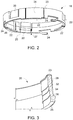
- FIG. 2 is a three-dimensional view of the ring (one part) holder 16 for holding interchangeable optical accessories (not shown in FIG. 2 ), according to an embodiment of the invention.
- the holder 16 has a round perimeter which can be represented by a circle perimeter line along a side wall 28 in a perimeter plane.
- the perimeter plane can be defined as any cross sectional plane perpendicular to a central axis (e.g., shown as the axis 15 in FIG. 1 ) of the ring holder 16 which crosses the side wall 28 of the ring holder 16.
- Top and bottom surfaces 23 and 25 define corresponding top and bottom planes (parallel to each other and to the perimeter plane) are perpendicular to the side wall 28.
- the side wall 28 is limited by the bottom and top planes/surfaces (which are parallel to each other and to the perimeter plane) and having the top opening for inserting optical accessories, and the bottom opening for the light to go through.
- the one part is configured to accommodate placing one or more optical accessories inside of the side wall 28, where each of the one or more optical accessories matches internal dimensions of the side wall 28 for smooth inserting of accessories to and forming a close fit of accessories with the side wall, as discussed herein.
- the ring holder 16 further comprises three springs 20, spaced along the perimeter 120° apart and vertically cut in the side wall 28 from the top surface (plane) 23 toward the bottom surface (plane) 25 until a predefined distance 27 from the bottom 25, where each spring 20 originated near the bottom plane 25 is tilted inward from the perimeter (toward the top plane 25) by a predefined extent (distance/angle). Then, when an optical accessory is inserted into the ring holder 16 through the top opening, at least one (may be more than one) of the springs 20 is manually bent outward of the perimeter to allow this accessory to slide down inside the side wall. After the manually bent at least one spring 20 being brought back to the original position by a spring effect, the multiple springs 20 can tightly hold the optical accessory in place.
- the ring holder 16 further comprises three ledges 22, spaced along the perimeter 120° apart and attached to a bottom surface 25 of the side wall 28.
- the three ledges 22 are configured to keep optical accessories from falling down from the ring holder 16.
- the ring holder 16 when placed in a lighting fixture 10 (e.g., as shown in FIG.1 ), can be held in place by a spring force generated by bended legs 24 spaced along the perimeter and attached to the bottom surface 25 of the side wall 28.
- the bended legs 24 may comprise three bended legs 120° apart.
- the ring holder 16 (comprising the one part) can be removed from and interchanged in the lighting fixture without any additional lock feature (or the like), for loading different optical accessories, as stated herein.
- an outside dimension of the one or more optical accessories and an inside dimension of the side wall 28 may have a similar circular shape and dimensions for providing smooth inserting of the optical accessories to and forming a close fit of accessories with the side wall 28.
- the inside surface of the side wall 28 can comprise at least two vertical grooves of different sizes 26 (only one groove is visible in FIG. 2 ) for allowing only one direction of installation of corresponding optical accessories (e.g., a diffuser) when inserted into the ring holder 16, by matching with corresponding features complimenting the at least two vertical grooves on the corresponding optical accessory (see an example in FIG. 5B ).
- corresponding optical accessories e.g., a diffuser
- the ring holder 16 can be made of a plastic material using injection molding.
- FIG. 3 shows an exemplary view of a spring 20 comprising notches 32, 34 and 36, e.g., parallel to the bottom surface 25, along the internal surface of the side wall 28, at predefined distances from the bottom 25 (e.g., equally spaced) in order to push forward and hold each inserted optical accessory sturdy in place. This also helps to keep accessories from becoming loose during shipping and handling.
- FIGS. 4A and 4B further demonstrate how the spring notches may be used for holding the optical accessories, according to an embodiment of the invention.
- FIG. 4A shows an exemplary cross-sectional view 40a of the ring holder 16 assembled with an optical accessory 41, which can be an optical filter (for selecting specific wavelength of the light output), a diffuser (to alter light beam angles), or the like.
- the spring 20 with the notch/groove 36 (see FIG. 3 ) is holding the optical accessory 41 in place.
- FIG. 4B shows an exemplary cross-sectional view 40b of the ring holder 16, when a second optical accessory 42 is inserted on the top of the optical accessory 41.
- a next groove 34 see FIG. 3 ) becomes the dominant component in holding both components 41 and 42 in place as shown in FIG. 4B .
- FIGS. 5A, 5B , 5C and 5D show exemplary views of assembling the ring holder 16 with two optical accessories 51 and 52, according to an embodiment of the invention described herein.
- FIG. 5A is a view 50a of the ring holder 16 to be assembled with a diffuser 51 and a Hexcel Louver 52.
- the Hexcel Louver 52 can be made of a metal or plastic material and have a honeycomb shape, for eliminating light glare in the output light of the light fixture (e.g., shown in FIG. 1 ).
- FIG. 5B is a top view 50b of the ring holder 16 assembled with the diffuser 51.
- the diffuser design requires diffuser's one side facing the light source (e.g., LED), thus there is only one way it can be placed in the ring holder 16. That is achieved using complimentary and matching features (groves-like) 26a and 26b of different sizes as discussed above. Also, it is clearly shown how the springs 20 hold the diffuser 51 in place.
- FIG. 5C is a top view 50c of the ring holder 16 assembled with the Hexcel Louver 52 on the top of the diffuser 51. It is clearly shown how the springs 20 hold the Hexcel Louver 52 and the diffuser 51 in place.
- FIG. 5D is a cross sectional view 50d of the ring holder 16 assembled with the Hexcel Louver 52 on the top of the diffuser 51.
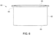
- FIG. 6 is exemplary view of a snoot (optical accessory) 60.
- the snoot 60 can be made of a metal or plastic material and can be used in the ring holder 16 for narrowing the light beam and reducing glare.
- the snoot 60 comprises a hollow cylinder 62 having ends 63 and 65, and further having a flange 66 at the end 65 of the cylinder 62.
- the external diameter of the flange 66 is matched to the internal diameter of the side wall 28 in FIG. 2 , so that the snoot 60 can be inserted into the ring holder 16 through the top 23, and slid in until the flange 66 is placed on the ledges 22 and then secured by the springs 20.
- a bottom portion in the light fixture 10 shown in Figure 1 would need to be removed to access the ring holder 16 comprising the snoot 60.
- the snoot 60 needs to be the first accessory inserted into the ring holder 16, so that additional optical accessories can be placed on the top of it if necessary.
- the light accessory holder has many advantages associated with the novel and unique features which include (but are not limited to):
Landscapes
- Engineering & Computer Science (AREA)
- General Engineering & Computer Science (AREA)
- Fastening Of Light Sources Or Lamp Holders (AREA)
- Non-Portable Lighting Devices Or Systems Thereof (AREA)
Abstract
Description
- The invention generally relates to lighting systems. More particularly but not exclusively, this invention relates to a light accessory holder for placing and interchanging multiple optical accessories in a lighting fixture.
- In track lighting and other light fixture envelopes, it is beneficial to use diffusers, glass, or other items to change a beam pattern or a light color. These items, referred to as accessories, are required by some customers so they can have different light outputs from the same light fixture. In retail applications for example, customers will want specific accessory combinations for different displays within the store. Also in environments in which the lighting requirements change from time to time, for example, in theaters, galleries, museums, etc., it may be necessary to replace or exchange some or all of the accessory elements installed in a particular fixture. This creates a necessity to provide removal and/or exchange of accessory elements to meet the customers need. Mechanically holding these accessories in place becomes a challenge, as it is difficult to determine the number and type of accessories that will be wanted. Multiple mechanical pieces, or multiple holders may be necessary to solve this challenge using conventional means.
- According to an aspect of the invention, a holder (e.g., removable, interchangeable and made by injection molding from a plastic material), in a lighting fixture for placing interchangeable optical accessories near a light source (e.g., one or more LEDs), comprising: one part, having a closed perimeter structure with a side wall crossing a perimeter (such as a circle, rectangle, ellipse, etc.) and perpendicular to a perimeter plane, the side wall being limited by bottom and top planes and having top and bottom openings (e.g., the bottom and top planes being parallel), the one part is configured to accommodate placing one or more optical accessories inside the side wall, where each of the one or more optical accessories matches internal dimensions of the side wall for smooth inserting to and for forming a close fit with internal surfaces of the side wall, the one part further comprises: multiple springs, spaced along the perimeter and vertically cut in the side wall from the top plane toward the bottom plane until a predefined distance from the bottom plane, where each spring originated near the bottom plane is tilted inward from the perimeter by a predefined extent, so that when each accessory of the one or more optical accessories is inserted into the one part through the top opening, at least one of the multiple springs is manually bent outward of the perimeter to allow the each accessory to slide down inside the side wall, and then, after the at least one spring being brought back to an original position by a spring effect, the multiple springs tightly hold the each optical accessory in place; and multiple ledges, spaced along the perimeter on the bottom plane and attached to the side wall, configured to keep optical accessories from falling down. Further, the holder with a circular perimeter can comprise a ring holder.
- According further to the aspect of the invention, each of the multiple springs may comprise notches, parallel to the bottom plane, along the perimeter, at different distances from the bottom plane in order to push forward and hold the each inserted accessory in a desired position. Further the multiple springs can comprise three strings 120° apart.
- According further to the aspect of the invention, the holder, when placed in a lighting fixture, may be held in place by a spring force generating by bended legs of the holder spaced along the perimeter and attached to a bottom surface of the side wall. Further, the bended legs may be 120° apart.
- Still further according to the aspect of the invention, tan inside surface of the side wall may comprise at least two vertical grooves of different sizes for allowing only one direction of installation of corresponding optical accessories when inserted into the holder by matching with corresponding features complimenting the at least two vertical grooves on the corresponding optical accessories.
- According further to the aspect of the invention, one of the one or more optical accessories may comprise a diffuser, an optical filter, and a Hexcel Louver.
- These and other features and aspects of the present disclosure will become better understood when the following detailed description is read, with reference to the accompanying drawings, in which like characters represent like parts throughout the drawings, wherein:
-
FIG. 1 is a sectional view of an exemplary light fixture, according to an embodiment of the invention; -
FIG. 2 is a three-dimensional view of a ring holder implemented as one part for holding interchangeable optical accessories, according to an embodiment of the invention; -
FIG. 3 is an exemplary view of a spring with notches configured to push forward and hold multiple optical accessories, according to an embodiment of the invention; -
FIGS. 4A and 4B are exemplary cross-sectional views demonstrating how the spring notches are used for holding the optical accessories in the ring holder, according to an embodiment of the invention; -
FIGS. 5A, 5B ,5C and 5D are exemplary views for illustration of assembling the ring holder with two optical accessories, according to an embodiment of the invention described herein; and -
FIG. 6 is an exemplary view of a snoot (optical accessory) for reducing light glare, which can be used in a ring holder according to an embodiment of the invention. - A new light accessory holder, comprising only one part, for placing and interchanging multiple optical accessories in a lighting fixture near/in front of a light sources is presented. The holder can use multiple notched springs (e.g., three) to push accessories forward and holds them in place. The holder may be removable from the lighting fixture, so the user can load into the holder whatever accessories are needed, and then return the re-loaded holder into the light fixture. According to an embodiment described herein, multiple accessories form one to N (N is a finite number, e.g., N=3) can be placed in the holder near/in front of a light source. Accessories include but are not limited to diffusers, glass components (optical filers), Hexcel Louvers, snoots, or other objects that are intended to alter the color or shape of a light source.
- According to an embodiment of the invention, a removable/interchangeable holder (in a lighting fixture) can comprise only one part, for placing interchangeable optical accessories near a light source (e.g., light emitting diode, LED). The one part holder may have a closed perimeter structure with a side wall crossing a perimeter/perimeter line (e.g., a circle, a rectangle, an ellipse or the like) and perpendicular to a perimeter plane comprising the perimeter/perimeter line. The side wall may be limited by bottom and top surfaces/planes (e.g., these surface/planes may be parallel to each other and to the perimeter plane) and having corresponding top and bottom openings. The one part may be configured to accommodate placing of one or more optical accessories inside of the side wall, where each of the one or more optical accessories matches internal dimensions of the side wall for smooth inserting to and for forming a close fit with the internal surfaces of the side wall.
- The one part can further comprise multiple springs, spaced along the perimeter (e.g., three springs 120° apart) and vertically cut in the side wall from the top surface/plane toward the bottom surface/plane until a predefined distance from the bottom surface/plane, where each spring originated near the bottom plane is tilted inward from the perimeter (toward the top plane) by a predefined extent (angle/distance), so that when each accessory of the one or more optical accessories is inserted into the one part through the top opening, at least one of the multiple springs is manually bent outward of the perimeter to allow the each accessory to slide down inside the side wall, and then the multiple springs, after being back to original positions by a spring effect, tightly hold the each optical accessory in place. The one part can further comprise multiple ledges, spaced along the perimeter and attached to a bottom surface of the side wall for keeping optical accessories from falling down.
- According to a further embodiment, each of the multiple springs may comprise notches (e.g., as shown in
FIG. 3 ), parallel to the bottom plane (or the top plane), along the perimeter, at different distances (e.g., equally spaced) from the bottom plane in order to push forward and hold each inserted accessory sturdy in a desired position. - According to another embodiment, the holder, when placed in a lighting fixture (as shown in
FIG.1 ), can be held in place by a spring force generated by bended legs of the holder spaced along the perimeter and attached to a bottom surface of the side wall. For example, the bended legs may comprise three bended legs 120° apart. Moreover, the holder (comprising one part) can be removed from and interchanged in the lighting fixture without any additional lock feature, for loading different optical accessories. - According to further embodiments, surfaces of the one or more optical accessories, when placed in the holder, can be perpendicular to the side wall. Also, the holder and the inserted one or more optical accessories can have a common (central) optical axis parallel to the side wall.
- Furthermore, an outside dimension of the one or more optical accessories and an inside dimension of the side wall may be matched, where the outside dimension of the one or more optical accessories is smaller than the inside dimensions of the side wall by a predefined small value for providing smooth inserting of accessories to and forming a close fit of accessories with the side wall.
- According to a further embodiment, an inside surface of the side wall can comprise at least two vertical grooves of different sizes for allowing only one direction of installation of corresponding optical accessories (e.g., a diffuser) when inserted into the holder, by matching with corresponding features complimenting the at least two vertical grooves on the corresponding optical accessories.
- It is further noted that the holder can be made of a plastic material using, for example, injection molding. The plastic material can be a type of polycarbonate (PC) or its variations, a type of ABS (acrylonitrile-butadiene-styrene copolymer), a material like polypropylene and the like. The injection molding seems to be very feasible manufacturing method to create this holder described herein, but possibly other methods, like 3D printing technology, can be used as well.
-
FIGS. 1-8 illustrate construction, performance and application of a circular (one part) holder, as described in further detail below. Similar or identical elements shown in different figures are designated using the same reference numbers. -
FIG. 1 is a sectional view of an exemplary light (track)fixture 10, according to an embodiment of the invention. Thefixture 10 comprises alight fixture housing 11, a LED source 12 (e.g., one or more LEDs), optics 14 (e.g., one or more lenses), an accessory ring holder 16 (which is a one part holder implemented as a ring), and acap 18. The light is emerged from a bottom of thefixture 10 after passing through the optical accessories placed in thering holder 16. An optical axis of the emerging light can correspond to aphysical axis 15 of theLEDs source 12,optics 14 and thering holder 16. When thecap 18 is removed, thering holder 16 can be removed and exchanged with different optical accessories, as described herein. -
FIG. 2 is a three-dimensional view of the ring (one part)holder 16 for holding interchangeable optical accessories (not shown inFIG. 2 ), according to an embodiment of the invention. Theholder 16 has a round perimeter which can be represented by a circle perimeter line along aside wall 28 in a perimeter plane. The perimeter plane can be defined as any cross sectional plane perpendicular to a central axis (e.g., shown as theaxis 15 inFIG. 1 ) of thering holder 16 which crosses theside wall 28 of thering holder 16. Top andbottom surfaces side wall 28. Theside wall 28 is limited by the bottom and top planes/surfaces (which are parallel to each other and to the perimeter plane) and having the top opening for inserting optical accessories, and the bottom opening for the light to go through. The one part is configured to accommodate placing one or more optical accessories inside of theside wall 28, where each of the one or more optical accessories matches internal dimensions of theside wall 28 for smooth inserting of accessories to and forming a close fit of accessories with the side wall, as discussed herein. - Moreover, the
ring holder 16 further comprises threesprings 20, spaced along the perimeter 120° apart and vertically cut in theside wall 28 from the top surface (plane) 23 toward the bottom surface (plane) 25 until apredefined distance 27 from the bottom 25, where eachspring 20 originated near thebottom plane 25 is tilted inward from the perimeter (toward the top plane 25) by a predefined extent (distance/angle). Then, when an optical accessory is inserted into thering holder 16 through the top opening, at least one (may be more than one) of thesprings 20 is manually bent outward of the perimeter to allow this accessory to slide down inside the side wall. After the manually bent at least onespring 20 being brought back to the original position by a spring effect, themultiple springs 20 can tightly hold the optical accessory in place. - The
ring holder 16 further comprises threeledges 22, spaced along the perimeter 120° apart and attached to abottom surface 25 of theside wall 28. The threeledges 22 are configured to keep optical accessories from falling down from thering holder 16. - According to another embodiment, the
ring holder 16, when placed in a lighting fixture 10 (e.g., as shown inFIG.1 ), can be held in place by a spring force generated bybended legs 24 spaced along the perimeter and attached to thebottom surface 25 of theside wall 28. For example, thebended legs 24 may comprise three bended legs 120° apart. Moreover, the ring holder 16 (comprising the one part) can be removed from and interchanged in the lighting fixture without any additional lock feature (or the like), for loading different optical accessories, as stated herein. - Moreover, an outside dimension of the one or more optical accessories and an inside dimension of the
side wall 28 may have a similar circular shape and dimensions for providing smooth inserting of the optical accessories to and forming a close fit of accessories with theside wall 28. - According to a further embodiment, the inside surface of the
side wall 28 can comprise at least two vertical grooves of different sizes 26 (only one groove is visible inFIG. 2 ) for allowing only one direction of installation of corresponding optical accessories (e.g., a diffuser) when inserted into thering holder 16, by matching with corresponding features complimenting the at least two vertical grooves on the corresponding optical accessory (see an example inFIG. 5B ). - It is further noted that the
ring holder 16 can be made of a plastic material using injection molding. -
FIG. 3 shows an exemplary view of aspring 20 comprisingnotches bottom surface 25, along the internal surface of theside wall 28, at predefined distances from the bottom 25 (e.g., equally spaced) in order to push forward and hold each inserted optical accessory sturdy in place. This also helps to keep accessories from becoming loose during shipping and handling.FIGS. 4A and 4B further demonstrate how the spring notches may be used for holding the optical accessories, according to an embodiment of the invention. -
FIG. 4A shows an exemplarycross-sectional view 40a of thering holder 16 assembled with anoptical accessory 41, which can be an optical filter (for selecting specific wavelength of the light output), a diffuser (to alter light beam angles), or the like. Thespring 20 with the notch/groove 36 (seeFIG. 3 ) is holding theoptical accessory 41 in place. -
FIG. 4B shows an exemplarycross-sectional view 40b of thering holder 16, when a secondoptical accessory 42 is inserted on the top of theoptical accessory 41. In this case, as thespring 20 is pushed out, anext groove 34 seeFIG. 3 ) becomes the dominant component in holding bothcomponents FIG. 4B . -
FIGS. 5A, 5B ,5C and 5D show exemplary views of assembling thering holder 16 with twooptical accessories FIG. 5A is aview 50a of thering holder 16 to be assembled with adiffuser 51 and aHexcel Louver 52. TheHexcel Louver 52 can be made of a metal or plastic material and have a honeycomb shape, for eliminating light glare in the output light of the light fixture (e.g., shown inFIG. 1 ). -
FIG. 5B is atop view 50b of thering holder 16 assembled with thediffuser 51. In this example the diffuser design requires diffuser's one side facing the light source (e.g., LED), thus there is only one way it can be placed in thering holder 16. That is achieved using complimentary and matching features (groves-like) 26a and 26b of different sizes as discussed above. Also, it is clearly shown how thesprings 20 hold thediffuser 51 in place. -
FIG. 5C is atop view 50c of thering holder 16 assembled with theHexcel Louver 52 on the top of thediffuser 51. It is clearly shown how thesprings 20 hold theHexcel Louver 52 and thediffuser 51 in place. FinallyFIG. 5D is a crosssectional view 50d of thering holder 16 assembled with theHexcel Louver 52 on the top of thediffuser 51. -
FIG. 6 is exemplary view of a snoot (optical accessory) 60. Thesnoot 60 can be made of a metal or plastic material and can be used in thering holder 16 for narrowing the light beam and reducing glare. Thesnoot 60 comprises ahollow cylinder 62 having ends 63 and 65, and further having aflange 66 at theend 65 of thecylinder 62. The external diameter of theflange 66 is matched to the internal diameter of theside wall 28 inFIG. 2 , so that thesnoot 60 can be inserted into thering holder 16 through the top 23, and slid in until theflange 66 is placed on theledges 22 and then secured by thesprings 20. - It is noted that a bottom portion in the
light fixture 10 shown inFigure 1 would need to be removed to access thering holder 16 comprising thesnoot 60. Thesnoot 60 needs to be the first accessory inserted into thering holder 16, so that additional optical accessories can be placed on the top of it if necessary. - Thus, the light accessory holder has many advantages associated with the novel and unique features which include (but are not limited to):
- one piece simplified design which can provide lower manufacturing cost,
- notched design holding accessories in place,
- customization of components can be done at the installation site and does not require ordering additional mechanical component,
- customers can change their existing light fixture by using different accessories without having to buy a new light fixture,
- light fixture can have multiple configurations without ordering additional mechanical components, and
- a universal looking fixture is provided even if accessories are changed for light quality purposes.
- Unless defined otherwise, technical and scientific terms used herein have the same meaning as is commonly understood by one having ordinary skill in the art to which this disclosure belongs. The terms "first", "second", and the like, as used herein, do not denote any order, quantity, or importance, but rather are employed to distinguish one element from another. Also, the terms "a" and "an" do not denote a limitation of quantity, but rather denote the presence of at least one of the referenced items. The use of "including," "comprising" or "having" and variations thereof herein are meant to encompass the items listed thereafter and equivalents thereof, as well as additional items. The terms "connected" and "coupled" are not restricted to physical or mechanical connections or couplings, and can include electrical and optical connections or couplings, whether direct or indirect.
- Furthermore, the skilled artisan will recognize the interchangeability of various features from different embodiments. The various features described, as well as other known equivalents for each feature, can be mixed and matched by one of ordinary skill in this art, to construct additional systems and techniques in accordance with principles of this disclosure.
- In describing alternate embodiments of the apparatus claimed, specific terminology is employed for the sake of clarity. The invention, however, is not intended to be limited to the specific terminology so selected. Thus, it is to be understood that each specific element includes all technical equivalents that operate in a similar manner to accomplish similar functions.
- It is to be understood that the foregoing description is intended to illustrate and not to limit the scope of the invention, which is defined by the scope of the appended claims. Other embodiments are within the scope of the following claims.
- It is noted that various non-limiting embodiments described and claimed herein may be used separately, combined or selectively combined for specific applications.
- Further, some of the various features of the above non-limiting embodiments may be used to advantage, without the corresponding use of other described features. The foregoing description should therefore be considered as merely illustrative of the principles, teachings and exemplary embodiments of this invention, and not in limitation thereof.
- Various aspects and embodiments of the present invention are defined by the following clauses:
- 1. A holder, in a lighting fixture for placing interchangeable optical accessories near a light source, comprising:
- one part, having a closed perimeter structure with a side wall crossing a perimeter and perpendicular to a perimeter plane, the side wall being limited by bottom and top planes and having top and bottom openings, the one part is configured to accommodate placing one or more optical accessories inside the side wall, where each of the one or more optical accessories matches internal dimensions of the side wall for smooth inserting to and for forming a close fit with internal surfaces of the side wall, the one part further comprises:
- multiple springs, spaced along the perimeter and vertically cut in the side wall from the top plane toward the bottom plane until a predefined distance from the bottom plane, where each spring originated near the bottom plane is tilted inward from the perimeter by a predefined extent, so that when each accessory of the one or more optical accessories is inserted into the one part through the top opening, at least one of the multiple springs is manually bent outward of the perimeter to allow the each accessory to slide down inside the side wall, and then, after the at least one spring being brought back to an original position by a spring effect, the multiple springs tightly hold the each optical accessory in place; and
- multiple ledges, spaced along the perimeter on the bottom plane and attached to the side wall, configured to keep optical accessories from falling down.
- one part, having a closed perimeter structure with a side wall crossing a perimeter and perpendicular to a perimeter plane, the side wall being limited by bottom and top planes and having top and bottom openings, the one part is configured to accommodate placing one or more optical accessories inside the side wall, where each of the one or more optical accessories matches internal dimensions of the side wall for smooth inserting to and for forming a close fit with internal surfaces of the side wall, the one part further comprises:
- 2. The holder of clause 1, wherein each of the multiple springs comprises notches, parallel to the bottom plane, along the perimeter, at different distances from the bottom plane in order to push forward and hold the each inserted accessory in a desired position.
- 3. The holder of clause 1, when placed in a lighting fixture, is held in place by a spring force generating by bended legs of the holder spaced along the perimeter and attached to a bottom surface of the side wall.
- 4. The holder of clause 3, wherein the bended legs are 120° apart.
- 5. The holder of clause 1, wherein the holder is removable from and interchangeable in the lighting fixture, without any additional lock feature, for loading different optical accessories.
- 6. The holder of clause 1, wherein exposed to light surfaces of the one or more optical accessories, when placed in the holder, are perpendicular to the side wall.
- 7. The holder of clause 1, wherein the perimeter comprises a circle.
- 8. The holder of clause 1, wherein the holder and the inserted one or more optical accessories have a common optical axis parallel to the side wall.
- 9. The holder of clause 1, wherein the perimeter comprises a rectangle.
- 10. The holder of clause 1, wherein the perimeter comprises an ellipse.
- 11. The holder of clause 1, wherein an outside dimension of the one or more optical accessories and a corresponding inside dimension of the side wall are matched, where the outside dimension of the one or more optical accessories being smaller than the inside dimensions of the side wall by a predefined small value to provide said smooth inserting and for forming a close fit with the side wall.
- 12. The holder of clause 1, wherein the multiple springs comprise three strings 120° apart.
- 13. The holder of clause 1, wherein an inside surface of the side wall comprises at least two vertical grooves of different sizes for allowing only one direction of installation of corresponding optical accessories when inserted into the holder by matching with corresponding features complimenting the at least two vertical grooves on the corresponding optical accessories.
- 14. The holder of clause 1, wherein the bottom and top planes are parallel.
- 15. The holder of clause 1, wherein the holder is made of a plastic material using injection molding.
- 16. The holder of clause 1, wherein one of the one or more optical accessories comprises a diffuser.
- 17. The holder of clause 1, wherein one of the one or more optical accessories comprises an optical filter.
- 18. The holder of clause 1, wherein one of the one or more optical accessories comprises a Hexcel Louver.
- 19. The holder of clause 1, wherein one of the one or more optical accessories comprises a snoot.
- 20. The holder of clause 1, wherein the light source comprises one or more light emitting diodes (LEDs).
Claims (14)
- A holder (16), in a lighting fixture (10) for placing interchangeable optical accessories (51, 52) near a light source (12), comprising:one part, having a closed perimeter structure with a side wall (28) crossing a perimeter and perpendicular to a perimeter plane, the side wall (28) being limited by bottom and top planes (23, 25) and having top and bottom openings, the one part is configured to accommodate placing one or more optical accessories (41, 42) inside the side wall (28), where each of the one or more optical accessories (41, 42) matches internal dimensions of the side wall (28) for smooth inserting to and for forming a close fit with internal surfaces of the side wall (28), the one part further comprises:multiple springs (20), spaced along the perimeter and vertically cut in the side wall (28) from the top plane (25) toward the bottom plane (23) until a predefined distance from the bottom plane (23), where each spring (20) originated near the bottom plane (23) is tilted inward from the perimeter by a predefined extent, so that when each accessory of the one or more optical accessories (41,42) is inserted into the one part through the top opening, at least one of the multiple springs (20) is manually bent outward of the perimeter to allow the each accessory (41, 42) to slide down inside the side wall (28), and then, after the at least one spring (20) being brought back to an original position by a spring effect, the multiple springs (20) tightly hold the each optical accessory (41, 42) in place; andmultiple ledges (22), spaced along the perimeter on the bottom plane (23) and attached to the side wall (28), configured to keep optical accessories (41, 42) from falling down.
- The holder (16) of claim 1, wherein each of the multiple springs (20) comprises notches (32, 34, 36), parallel to the bottom plane (23), along the perimeter, at different distances from the bottom plane (23) in order to push forward and hold the each inserted accessory (41, 42) in a desired position.
- The holder (16) of claim 1 or claim 2, when placed in a lighting fixture (10), is held in place by a spring force generating by bended legs (24) of the holder (16) spaced along the perimeter and attached to a bottom surface (25) of the side wall (28) and wherein the bended legs (24) are 120° apart.
- The holder (16) of any preceding claim, wherein the holder (16) is removable from and interchangeable in the lighting fixture (10), without any additional lock feature, for loading different optical accessories (41, 42).
- The holder (16) of any preceding claim, wherein exposed to light surfaces of the one or more optical accessories (41, 42), when placed in the holder (16), are perpendicular to the side wall (28).
- The holder (16) of any preceding claim, wherein the perimeter comprises a circle.
- The holder (16) of claim 1, wherein the holder (16) and the inserted one or more optical accessories (51, 52) have a common optical axis (15) parallel to the side wall (28) and the holder (16) is made of a plastic material using injection molding.
- The holder (16) of any preceding claim, wherein the perimeter comprises a rectangle or ellipse.
- The holder (16) of any preceding claim, wherein an outside dimension of the one or more optical accessories (41, 42) and a corresponding inside dimension of the side wall (28) are matched, where the outside dimension of the one or more optical accessories (41, 42) being smaller than the inside dimensions of the side wall (28) by a predefined small value to provide said smooth inserting and for forming a close fit with the side wall (28).
- The holder (16) of any preceding claim, wherein the multiple springs (20) comprise three strings 120° apart.
- The holder (16) of any preceding claim, wherein an inside surface of the side wall (28) comprises at least two vertical grooves (26) of different sizes for allowing only one direction of installation of corresponding optical accessories (41, 42) when inserted into the holder (16) by matching with corresponding features complimenting the at least two vertical grooves (26) on the corresponding optical accessories (41, 42).
- The holder (16) of any preceding claim, wherein the bottom and top planes (23, 25) are parallel.
- The holder (16) of any preceding claim, wherein the light source (12) comprises one or more light emitting diodes (LEDs).
- The holder (16) of any preceding claim, wherein one of the one or more optical accessories comprises a diffuser (51) or an optical filter or a Hexcel Louver (52) or a snoot (60).
Applications Claiming Priority (1)
| Application Number | Priority Date | Filing Date | Title |
|---|---|---|---|
| US15/163,751 US9933138B2 (en) | 2016-05-25 | 2016-05-25 | Holder for multiple interchangeable light accessories |
Publications (2)
| Publication Number | Publication Date |
|---|---|
| EP3249288A1 true EP3249288A1 (en) | 2017-11-29 |
| EP3249288B1 EP3249288B1 (en) | 2019-04-10 |
Family
ID=58714953
Family Applications (1)
| Application Number | Title | Priority Date | Filing Date |
|---|---|---|---|
| EP17171186.4A Not-in-force EP3249288B1 (en) | 2016-05-25 | 2017-05-15 | A holder for multiple interchangeable light accessories |
Country Status (4)
| Country | Link |
|---|---|
| US (1) | US9933138B2 (en) |
| EP (1) | EP3249288B1 (en) |
| CA (1) | CA2966684A1 (en) |
| MX (1) | MX2017006765A (en) |
Citations (2)
| Publication number | Priority date | Publication date | Assignee | Title |
|---|---|---|---|---|
| DE202007004216U1 (en) * | 2006-09-05 | 2007-05-31 | Bruckner, Attila A. | Masking plate for illumination devices, has masking plate fixing device with spring clamps, and honey comb ratchet disc that absorbs plate rays that occurs under cap, where reflected rays are passed via disc |
| US20130107570A1 (en) * | 2011-10-26 | 2013-05-02 | Enlight Corporation | Led lamp |
Family Cites Families (7)
| Publication number | Priority date | Publication date | Assignee | Title |
|---|---|---|---|---|
| US3117732A (en) * | 1961-08-14 | 1964-01-14 | Preston A Jones | Light fixture apparatus |
| US3130949A (en) * | 1962-07-02 | 1964-04-28 | Century Lighting Inc | Support for lighting and building fixtures and the like |
| US6896394B2 (en) * | 2002-05-31 | 2005-05-24 | #9060-0495 Quebec, Inc. | Recessed light fixture |
| US6942368B1 (en) | 2003-10-17 | 2005-09-13 | Lighting Services Inc. | Accessory cartridge for lighting fixture |
| US7488092B2 (en) | 2005-08-05 | 2009-02-10 | Genlyte Thomas Group Llc | Track fixture with hinged accessory ring |
| US7563016B1 (en) | 2005-08-05 | 2009-07-21 | Genlyte Thomas Group, Llc | PAR track light with internal wire way |
| US7575345B2 (en) * | 2007-01-03 | 2009-08-18 | Venmar Ventilation, Inc | Lamp housing assembly |
-
2016
- 2016-05-25 US US15/163,751 patent/US9933138B2/en not_active Expired - Fee Related
-
2017
- 2017-05-11 CA CA2966684A patent/CA2966684A1/en not_active Abandoned
- 2017-05-15 EP EP17171186.4A patent/EP3249288B1/en not_active Not-in-force
- 2017-05-24 MX MX2017006765A patent/MX2017006765A/en unknown
Patent Citations (2)
| Publication number | Priority date | Publication date | Assignee | Title |
|---|---|---|---|---|
| DE202007004216U1 (en) * | 2006-09-05 | 2007-05-31 | Bruckner, Attila A. | Masking plate for illumination devices, has masking plate fixing device with spring clamps, and honey comb ratchet disc that absorbs plate rays that occurs under cap, where reflected rays are passed via disc |
| US20130107570A1 (en) * | 2011-10-26 | 2013-05-02 | Enlight Corporation | Led lamp |
Also Published As
| Publication number | Publication date |
|---|---|
| MX2017006765A (en) | 2018-09-06 |
| EP3249288B1 (en) | 2019-04-10 |
| US9933138B2 (en) | 2018-04-03 |
| US20170343192A1 (en) | 2017-11-30 |
| CA2966684A1 (en) | 2017-11-25 |
Similar Documents
| Publication | Publication Date | Title |
|---|---|---|
| US4339787A (en) | Christmas decoration | |
| CN105960562A (en) | Elongated multi-piece lens group and lamp with such lens group | |
| EP2927561A1 (en) | Lamp | |
| EP2734779B1 (en) | Lighting device and associated method | |
| WO2015038761A1 (en) | Catadioptric spotlight | |
| JP2017513193A5 (en) | ||
| US9933138B2 (en) | Holder for multiple interchangeable light accessories | |
| CN109073182A (en) | Luminescence unit and lamps apparatus for vehicle | |
| US12181131B2 (en) | Adjustable optical system for lighting units | |
| EP2924348B1 (en) | Lighting apparatus | |
| EP3543761A1 (en) | Device for condensing and changing light of mobile phone | |
| US20230341097A1 (en) | Optical cells for modular luminaires | |
| US9163809B2 (en) | Lighting system | |
| CN107036051A (en) | Lighting device | |
| EP3280949B1 (en) | Linear lighting apparatus | |
| JP6559862B1 (en) | Optical unit and LED lighting apparatus using the optical unit | |
| JP6231026B2 (en) | Remote beam shaping | |
| WO2015043980A1 (en) | Remote controllable lighting device | |
| JP2019029147A (en) | Lighting apparatus and light control member | |
| US20160091724A1 (en) | Stereoscopic kaleidoscope and projecting device | |
| EP3788301B1 (en) | Luminaire | |
| EP3034934B1 (en) | Nonlinear optical assembly of an alert light | |
| JP6440427B2 (en) | lighting equipment | |
| JP6920678B2 (en) | lighting equipment | |
| EP4202294A1 (en) | Indicator light |
Legal Events
| Date | Code | Title | Description |
|---|---|---|---|
| PUAI | Public reference made under article 153(3) epc to a published international application that has entered the european phase |
Free format text: ORIGINAL CODE: 0009012 |
|
| STAA | Information on the status of an ep patent application or granted ep patent |
Free format text: STATUS: THE APPLICATION HAS BEEN PUBLISHED |
|
| AK | Designated contracting states |
Kind code of ref document: A1 Designated state(s): AL AT BE BG CH CY CZ DE DK EE ES FI FR GB GR HR HU IE IS IT LI LT LU LV MC MK MT NL NO PL PT RO RS SE SI SK SM TR |
|
| AX | Request for extension of the european patent |
Extension state: BA ME |
|
| STAA | Information on the status of an ep patent application or granted ep patent |
Free format text: STATUS: REQUEST FOR EXAMINATION WAS MADE |
|
| 17P | Request for examination filed |
Effective date: 20180529 |
|
| RBV | Designated contracting states (corrected) |
Designated state(s): AL AT BE BG CH CY CZ DE DK EE ES FI FR GB GR HR HU IE IS IT LI LT LU LV MC MK MT NL NO PL PT RO RS SE SI SK SM TR |
|
| GRAP | Despatch of communication of intention to grant a patent |
Free format text: ORIGINAL CODE: EPIDOSNIGR1 |
|
| STAA | Information on the status of an ep patent application or granted ep patent |
Free format text: STATUS: GRANT OF PATENT IS INTENDED |
|
| INTG | Intention to grant announced |
Effective date: 20181128 |
|
| GRAS | Grant fee paid |
Free format text: ORIGINAL CODE: EPIDOSNIGR3 |
|
| GRAA | (expected) grant |
Free format text: ORIGINAL CODE: 0009210 |
|
| STAA | Information on the status of an ep patent application or granted ep patent |
Free format text: STATUS: THE PATENT HAS BEEN GRANTED |
|
| AK | Designated contracting states |
Kind code of ref document: B1 Designated state(s): AL AT BE BG CH CY CZ DE DK EE ES FI FR GB GR HR HU IE IS IT LI LT LU LV MC MK MT NL NO PL PT RO RS SE SI SK SM TR |
|
| REG | Reference to a national code |
Ref country code: GB Ref legal event code: FG4D |
|
| REG | Reference to a national code |
Ref country code: CH Ref legal event code: EP Ref country code: AT Ref legal event code: REF Ref document number: 1119176 Country of ref document: AT Kind code of ref document: T Effective date: 20190415 |
|
| REG | Reference to a national code |
Ref country code: IE Ref legal event code: FG4D |
|
| REG | Reference to a national code |
Ref country code: DE Ref legal event code: R096 Ref document number: 602017003158 Country of ref document: DE |
|
| REG | Reference to a national code |
Ref country code: NL Ref legal event code: MP Effective date: 20190410 |
|
| RAP2 | Party data changed (patent owner data changed or rights of a patent transferred) |
Owner name: CURRENT LIGHTING SOLUTIONS, LLC |
|
| REG | Reference to a national code |
Ref country code: LT Ref legal event code: MG4D |
|
| REG | Reference to a national code |
Ref country code: AT Ref legal event code: MK05 Ref document number: 1119176 Country of ref document: AT Kind code of ref document: T Effective date: 20190410 |
|
| PG25 | Lapsed in a contracting state [announced via postgrant information from national office to epo] |
Ref country code: NL Free format text: LAPSE BECAUSE OF FAILURE TO SUBMIT A TRANSLATION OF THE DESCRIPTION OR TO PAY THE FEE WITHIN THE PRESCRIBED TIME-LIMIT Effective date: 20190410 |
|
| PG25 | Lapsed in a contracting state [announced via postgrant information from national office to epo] |
Ref country code: NO Free format text: LAPSE BECAUSE OF FAILURE TO SUBMIT A TRANSLATION OF THE DESCRIPTION OR TO PAY THE FEE WITHIN THE PRESCRIBED TIME-LIMIT Effective date: 20190710 Ref country code: SE Free format text: LAPSE BECAUSE OF FAILURE TO SUBMIT A TRANSLATION OF THE DESCRIPTION OR TO PAY THE FEE WITHIN THE PRESCRIBED TIME-LIMIT Effective date: 20190410 Ref country code: AL Free format text: LAPSE BECAUSE OF FAILURE TO SUBMIT A TRANSLATION OF THE DESCRIPTION OR TO PAY THE FEE WITHIN THE PRESCRIBED TIME-LIMIT Effective date: 20190410 Ref country code: FI Free format text: LAPSE BECAUSE OF FAILURE TO SUBMIT A TRANSLATION OF THE DESCRIPTION OR TO PAY THE FEE WITHIN THE PRESCRIBED TIME-LIMIT Effective date: 20190410 Ref country code: HR Free format text: LAPSE BECAUSE OF FAILURE TO SUBMIT A TRANSLATION OF THE DESCRIPTION OR TO PAY THE FEE WITHIN THE PRESCRIBED TIME-LIMIT Effective date: 20190410 Ref country code: LT Free format text: LAPSE BECAUSE OF FAILURE TO SUBMIT A TRANSLATION OF THE DESCRIPTION OR TO PAY THE FEE WITHIN THE PRESCRIBED TIME-LIMIT Effective date: 20190410 Ref country code: PT Free format text: LAPSE BECAUSE OF FAILURE TO SUBMIT A TRANSLATION OF THE DESCRIPTION OR TO PAY THE FEE WITHIN THE PRESCRIBED TIME-LIMIT Effective date: 20190910 Ref country code: ES Free format text: LAPSE BECAUSE OF FAILURE TO SUBMIT A TRANSLATION OF THE DESCRIPTION OR TO PAY THE FEE WITHIN THE PRESCRIBED TIME-LIMIT Effective date: 20190410 |
|
| PG25 | Lapsed in a contracting state [announced via postgrant information from national office to epo] |
Ref country code: LV Free format text: LAPSE BECAUSE OF FAILURE TO SUBMIT A TRANSLATION OF THE DESCRIPTION OR TO PAY THE FEE WITHIN THE PRESCRIBED TIME-LIMIT Effective date: 20190410 Ref country code: RS Free format text: LAPSE BECAUSE OF FAILURE TO SUBMIT A TRANSLATION OF THE DESCRIPTION OR TO PAY THE FEE WITHIN THE PRESCRIBED TIME-LIMIT Effective date: 20190410 Ref country code: BG Free format text: LAPSE BECAUSE OF FAILURE TO SUBMIT A TRANSLATION OF THE DESCRIPTION OR TO PAY THE FEE WITHIN THE PRESCRIBED TIME-LIMIT Effective date: 20190710 Ref country code: PL Free format text: LAPSE BECAUSE OF FAILURE TO SUBMIT A TRANSLATION OF THE DESCRIPTION OR TO PAY THE FEE WITHIN THE PRESCRIBED TIME-LIMIT Effective date: 20190410 Ref country code: GR Free format text: LAPSE BECAUSE OF FAILURE TO SUBMIT A TRANSLATION OF THE DESCRIPTION OR TO PAY THE FEE WITHIN THE PRESCRIBED TIME-LIMIT Effective date: 20190711 |
|
| REG | Reference to a national code |
Ref country code: DE Ref legal event code: R119 Ref document number: 602017003158 Country of ref document: DE |
|
| PG25 | Lapsed in a contracting state [announced via postgrant information from national office to epo] |
Ref country code: IS Free format text: LAPSE BECAUSE OF FAILURE TO SUBMIT A TRANSLATION OF THE DESCRIPTION OR TO PAY THE FEE WITHIN THE PRESCRIBED TIME-LIMIT Effective date: 20190810 Ref country code: AT Free format text: LAPSE BECAUSE OF FAILURE TO SUBMIT A TRANSLATION OF THE DESCRIPTION OR TO PAY THE FEE WITHIN THE PRESCRIBED TIME-LIMIT Effective date: 20190410 |
|
| PG25 | Lapsed in a contracting state [announced via postgrant information from national office to epo] |
Ref country code: MC Free format text: LAPSE BECAUSE OF FAILURE TO SUBMIT A TRANSLATION OF THE DESCRIPTION OR TO PAY THE FEE WITHIN THE PRESCRIBED TIME-LIMIT Effective date: 20190410 Ref country code: CZ Free format text: LAPSE BECAUSE OF FAILURE TO SUBMIT A TRANSLATION OF THE DESCRIPTION OR TO PAY THE FEE WITHIN THE PRESCRIBED TIME-LIMIT Effective date: 20190410 Ref country code: RO Free format text: LAPSE BECAUSE OF FAILURE TO SUBMIT A TRANSLATION OF THE DESCRIPTION OR TO PAY THE FEE WITHIN THE PRESCRIBED TIME-LIMIT Effective date: 20190410 Ref country code: DK Free format text: LAPSE BECAUSE OF FAILURE TO SUBMIT A TRANSLATION OF THE DESCRIPTION OR TO PAY THE FEE WITHIN THE PRESCRIBED TIME-LIMIT Effective date: 20190410 Ref country code: EE Free format text: LAPSE BECAUSE OF FAILURE TO SUBMIT A TRANSLATION OF THE DESCRIPTION OR TO PAY THE FEE WITHIN THE PRESCRIBED TIME-LIMIT Effective date: 20190410 Ref country code: SK Free format text: LAPSE BECAUSE OF FAILURE TO SUBMIT A TRANSLATION OF THE DESCRIPTION OR TO PAY THE FEE WITHIN THE PRESCRIBED TIME-LIMIT Effective date: 20190410 |
|
| REG | Reference to a national code |
Ref country code: BE Ref legal event code: MM Effective date: 20190531 |
|
| PLBE | No opposition filed within time limit |
Free format text: ORIGINAL CODE: 0009261 |
|
| STAA | Information on the status of an ep patent application or granted ep patent |
Free format text: STATUS: NO OPPOSITION FILED WITHIN TIME LIMIT |
|
| PG25 | Lapsed in a contracting state [announced via postgrant information from national office to epo] |
Ref country code: LU Free format text: LAPSE BECAUSE OF NON-PAYMENT OF DUE FEES Effective date: 20190515 Ref country code: IT Free format text: LAPSE BECAUSE OF FAILURE TO SUBMIT A TRANSLATION OF THE DESCRIPTION OR TO PAY THE FEE WITHIN THE PRESCRIBED TIME-LIMIT Effective date: 20190410 Ref country code: SM Free format text: LAPSE BECAUSE OF FAILURE TO SUBMIT A TRANSLATION OF THE DESCRIPTION OR TO PAY THE FEE WITHIN THE PRESCRIBED TIME-LIMIT Effective date: 20190410 |
|
| 26N | No opposition filed |
Effective date: 20200113 |
|
| PG25 | Lapsed in a contracting state [announced via postgrant information from national office to epo] |
Ref country code: TR Free format text: LAPSE BECAUSE OF FAILURE TO SUBMIT A TRANSLATION OF THE DESCRIPTION OR TO PAY THE FEE WITHIN THE PRESCRIBED TIME-LIMIT Effective date: 20190410 |
|
| PG25 | Lapsed in a contracting state [announced via postgrant information from national office to epo] |
Ref country code: DE Free format text: LAPSE BECAUSE OF NON-PAYMENT OF DUE FEES Effective date: 20191203 Ref country code: IE Free format text: LAPSE BECAUSE OF NON-PAYMENT OF DUE FEES Effective date: 20190515 |
|
| PG25 | Lapsed in a contracting state [announced via postgrant information from national office to epo] |
Ref country code: SI Free format text: LAPSE BECAUSE OF FAILURE TO SUBMIT A TRANSLATION OF THE DESCRIPTION OR TO PAY THE FEE WITHIN THE PRESCRIBED TIME-LIMIT Effective date: 20190410 Ref country code: BE Free format text: LAPSE BECAUSE OF NON-PAYMENT OF DUE FEES Effective date: 20190531 |
|
| PG25 | Lapsed in a contracting state [announced via postgrant information from national office to epo] |
Ref country code: FR Free format text: LAPSE BECAUSE OF NON-PAYMENT OF DUE FEES Effective date: 20190610 |
|
| PG25 | Lapsed in a contracting state [announced via postgrant information from national office to epo] |
Ref country code: CH Free format text: LAPSE BECAUSE OF NON-PAYMENT OF DUE FEES Effective date: 20200531 Ref country code: LI Free format text: LAPSE BECAUSE OF NON-PAYMENT OF DUE FEES Effective date: 20200531 |
|
| PG25 | Lapsed in a contracting state [announced via postgrant information from national office to epo] |
Ref country code: CY Free format text: LAPSE BECAUSE OF FAILURE TO SUBMIT A TRANSLATION OF THE DESCRIPTION OR TO PAY THE FEE WITHIN THE PRESCRIBED TIME-LIMIT Effective date: 20190410 |
|
| PG25 | Lapsed in a contracting state [announced via postgrant information from national office to epo] |
Ref country code: MT Free format text: LAPSE BECAUSE OF FAILURE TO SUBMIT A TRANSLATION OF THE DESCRIPTION OR TO PAY THE FEE WITHIN THE PRESCRIBED TIME-LIMIT Effective date: 20190410 Ref country code: HU Free format text: LAPSE BECAUSE OF FAILURE TO SUBMIT A TRANSLATION OF THE DESCRIPTION OR TO PAY THE FEE WITHIN THE PRESCRIBED TIME-LIMIT; INVALID AB INITIO Effective date: 20170515 |
|
| GBPC | Gb: european patent ceased through non-payment of renewal fee |
Effective date: 20210515 |
|
| PG25 | Lapsed in a contracting state [announced via postgrant information from national office to epo] |
Ref country code: GB Free format text: LAPSE BECAUSE OF NON-PAYMENT OF DUE FEES Effective date: 20210515 |
|
| PG25 | Lapsed in a contracting state [announced via postgrant information from national office to epo] |
Ref country code: MK Free format text: LAPSE BECAUSE OF FAILURE TO SUBMIT A TRANSLATION OF THE DESCRIPTION OR TO PAY THE FEE WITHIN THE PRESCRIBED TIME-LIMIT Effective date: 20190410 |