EP3249257A1 - Damper device - Google Patents
Damper device Download PDFInfo
- Publication number
- EP3249257A1 EP3249257A1 EP16773208.0A EP16773208A EP3249257A1 EP 3249257 A1 EP3249257 A1 EP 3249257A1 EP 16773208 A EP16773208 A EP 16773208A EP 3249257 A1 EP3249257 A1 EP 3249257A1
- Authority
- EP
- European Patent Office
- Prior art keywords
- springs
- damper device
- spring
- circumferential direction
- elastic body
- Prior art date
- Legal status (The legal status is an assumption and is not a legal conclusion. Google has not performed a legal analysis and makes no representation as to the accuracy of the status listed.)
- Granted
Links
Images


Classifications
-
- F—MECHANICAL ENGINEERING; LIGHTING; HEATING; WEAPONS; BLASTING
- F16—ENGINEERING ELEMENTS AND UNITS; GENERAL MEASURES FOR PRODUCING AND MAINTAINING EFFECTIVE FUNCTIONING OF MACHINES OR INSTALLATIONS; THERMAL INSULATION IN GENERAL
- F16F—SPRINGS; SHOCK-ABSORBERS; MEANS FOR DAMPING VIBRATION
- F16F15/00—Suppression of vibrations in systems; Means or arrangements for avoiding or reducing out-of-balance forces, e.g. due to motion
- F16F15/10—Suppression of vibrations in rotating systems by making use of members moving with the system
- F16F15/12—Suppression of vibrations in rotating systems by making use of members moving with the system using elastic members or friction-damping members, e.g. between a rotating shaft and a gyratory mass mounted thereon
- F16F15/131—Suppression of vibrations in rotating systems by making use of members moving with the system using elastic members or friction-damping members, e.g. between a rotating shaft and a gyratory mass mounted thereon the rotating system comprising two or more gyratory masses
- F16F15/133—Suppression of vibrations in rotating systems by making use of members moving with the system using elastic members or friction-damping members, e.g. between a rotating shaft and a gyratory mass mounted thereon the rotating system comprising two or more gyratory masses using springs as elastic members, e.g. metallic springs
- F16F15/134—Wound springs
- F16F15/13469—Combinations of dampers, e.g. with multiple plates, multiple spring sets, i.e. complex configurations
- F16F15/13476—Combinations of dampers, e.g. with multiple plates, multiple spring sets, i.e. complex configurations resulting in a staged spring characteristic, e.g. with multiple intermediate plates
- F16F15/13484—Combinations of dampers, e.g. with multiple plates, multiple spring sets, i.e. complex configurations resulting in a staged spring characteristic, e.g. with multiple intermediate plates acting on multiple sets of springs
-
- F—MECHANICAL ENGINEERING; LIGHTING; HEATING; WEAPONS; BLASTING
- F16—ENGINEERING ELEMENTS AND UNITS; GENERAL MEASURES FOR PRODUCING AND MAINTAINING EFFECTIVE FUNCTIONING OF MACHINES OR INSTALLATIONS; THERMAL INSULATION IN GENERAL
- F16F—SPRINGS; SHOCK-ABSORBERS; MEANS FOR DAMPING VIBRATION
- F16F15/00—Suppression of vibrations in systems; Means or arrangements for avoiding or reducing out-of-balance forces, e.g. due to motion
- F16F15/10—Suppression of vibrations in rotating systems by making use of members moving with the system
- F16F15/12—Suppression of vibrations in rotating systems by making use of members moving with the system using elastic members or friction-damping members, e.g. between a rotating shaft and a gyratory mass mounted thereon
- F16F15/131—Suppression of vibrations in rotating systems by making use of members moving with the system using elastic members or friction-damping members, e.g. between a rotating shaft and a gyratory mass mounted thereon the rotating system comprising two or more gyratory masses
- F16F15/133—Suppression of vibrations in rotating systems by making use of members moving with the system using elastic members or friction-damping members, e.g. between a rotating shaft and a gyratory mass mounted thereon the rotating system comprising two or more gyratory masses using springs as elastic members, e.g. metallic springs
- F16F15/134—Wound springs
-
- F—MECHANICAL ENGINEERING; LIGHTING; HEATING; WEAPONS; BLASTING
- F16—ENGINEERING ELEMENTS AND UNITS; GENERAL MEASURES FOR PRODUCING AND MAINTAINING EFFECTIVE FUNCTIONING OF MACHINES OR INSTALLATIONS; THERMAL INSULATION IN GENERAL
- F16F—SPRINGS; SHOCK-ABSORBERS; MEANS FOR DAMPING VIBRATION
- F16F15/00—Suppression of vibrations in systems; Means or arrangements for avoiding or reducing out-of-balance forces, e.g. due to motion
- F16F15/10—Suppression of vibrations in rotating systems by making use of members moving with the system
- F16F15/12—Suppression of vibrations in rotating systems by making use of members moving with the system using elastic members or friction-damping members, e.g. between a rotating shaft and a gyratory mass mounted thereon
- F16F15/121—Suppression of vibrations in rotating systems by making use of members moving with the system using elastic members or friction-damping members, e.g. between a rotating shaft and a gyratory mass mounted thereon using springs as elastic members, e.g. metallic springs
- F16F15/123—Wound springs
- F16F15/12353—Combinations of dampers, e.g. with multiple plates, multiple spring sets, i.e. complex configurations
- F16F15/1236—Combinations of dampers, e.g. with multiple plates, multiple spring sets, i.e. complex configurations resulting in a staged spring characteristic, e.g. with multiple intermediate plates
- F16F15/12366—Combinations of dampers, e.g. with multiple plates, multiple spring sets, i.e. complex configurations resulting in a staged spring characteristic, e.g. with multiple intermediate plates acting on multiple sets of springs
- F16F15/12373—Combinations of dampers, e.g. with multiple plates, multiple spring sets, i.e. complex configurations resulting in a staged spring characteristic, e.g. with multiple intermediate plates acting on multiple sets of springs the sets of springs being arranged at substantially the same radius
-
- F—MECHANICAL ENGINEERING; LIGHTING; HEATING; WEAPONS; BLASTING
- F16—ENGINEERING ELEMENTS AND UNITS; GENERAL MEASURES FOR PRODUCING AND MAINTAINING EFFECTIVE FUNCTIONING OF MACHINES OR INSTALLATIONS; THERMAL INSULATION IN GENERAL
- F16D—COUPLINGS FOR TRANSMITTING ROTATION; CLUTCHES; BRAKES
- F16D3/00—Yielding couplings, i.e. with means permitting movement between the connected parts during the drive
- F16D3/02—Yielding couplings, i.e. with means permitting movement between the connected parts during the drive adapted to specific functions
- F16D3/12—Yielding couplings, i.e. with means permitting movement between the connected parts during the drive adapted to specific functions specially adapted for accumulation of energy to absorb shocks or vibration
-
- F—MECHANICAL ENGINEERING; LIGHTING; HEATING; WEAPONS; BLASTING
- F16—ENGINEERING ELEMENTS AND UNITS; GENERAL MEASURES FOR PRODUCING AND MAINTAINING EFFECTIVE FUNCTIONING OF MACHINES OR INSTALLATIONS; THERMAL INSULATION IN GENERAL
- F16F—SPRINGS; SHOCK-ABSORBERS; MEANS FOR DAMPING VIBRATION
- F16F15/00—Suppression of vibrations in systems; Means or arrangements for avoiding or reducing out-of-balance forces, e.g. due to motion
- F16F15/10—Suppression of vibrations in rotating systems by making use of members moving with the system
- F16F15/12—Suppression of vibrations in rotating systems by making use of members moving with the system using elastic members or friction-damping members, e.g. between a rotating shaft and a gyratory mass mounted thereon
- F16F15/121—Suppression of vibrations in rotating systems by making use of members moving with the system using elastic members or friction-damping members, e.g. between a rotating shaft and a gyratory mass mounted thereon using springs as elastic members, e.g. metallic springs
- F16F15/123—Wound springs
- F16F15/12353—Combinations of dampers, e.g. with multiple plates, multiple spring sets, i.e. complex configurations
- F16F15/1236—Combinations of dampers, e.g. with multiple plates, multiple spring sets, i.e. complex configurations resulting in a staged spring characteristic, e.g. with multiple intermediate plates
- F16F15/12366—Combinations of dampers, e.g. with multiple plates, multiple spring sets, i.e. complex configurations resulting in a staged spring characteristic, e.g. with multiple intermediate plates acting on multiple sets of springs
-
- F—MECHANICAL ENGINEERING; LIGHTING; HEATING; WEAPONS; BLASTING
- F16—ENGINEERING ELEMENTS AND UNITS; GENERAL MEASURES FOR PRODUCING AND MAINTAINING EFFECTIVE FUNCTIONING OF MACHINES OR INSTALLATIONS; THERMAL INSULATION IN GENERAL
- F16F—SPRINGS; SHOCK-ABSORBERS; MEANS FOR DAMPING VIBRATION
- F16F15/00—Suppression of vibrations in systems; Means or arrangements for avoiding or reducing out-of-balance forces, e.g. due to motion
- F16F15/10—Suppression of vibrations in rotating systems by making use of members moving with the system
- F16F15/12—Suppression of vibrations in rotating systems by making use of members moving with the system using elastic members or friction-damping members, e.g. between a rotating shaft and a gyratory mass mounted thereon
- F16F15/131—Suppression of vibrations in rotating systems by making use of members moving with the system using elastic members or friction-damping members, e.g. between a rotating shaft and a gyratory mass mounted thereon the rotating system comprising two or more gyratory masses
- F16F15/133—Suppression of vibrations in rotating systems by making use of members moving with the system using elastic members or friction-damping members, e.g. between a rotating shaft and a gyratory mass mounted thereon the rotating system comprising two or more gyratory masses using springs as elastic members, e.g. metallic springs
- F16F15/134—Wound springs
- F16F15/13407—Radially mounted springs
-
- F—MECHANICAL ENGINEERING; LIGHTING; HEATING; WEAPONS; BLASTING
- F16—ENGINEERING ELEMENTS AND UNITS; GENERAL MEASURES FOR PRODUCING AND MAINTAINING EFFECTIVE FUNCTIONING OF MACHINES OR INSTALLATIONS; THERMAL INSULATION IN GENERAL
- F16H—GEARING
- F16H45/00—Combinations of fluid gearings for conveying rotary motion with couplings or clutches
- F16H45/02—Combinations of fluid gearings for conveying rotary motion with couplings or clutches with mechanical clutches for bridging a fluid gearing of the hydrokinetic type
- F16H2045/0221—Combinations of fluid gearings for conveying rotary motion with couplings or clutches with mechanical clutches for bridging a fluid gearing of the hydrokinetic type with damping means
- F16H2045/0226—Combinations of fluid gearings for conveying rotary motion with couplings or clutches with mechanical clutches for bridging a fluid gearing of the hydrokinetic type with damping means comprising two or more vibration dampers
- F16H2045/0231—Combinations of fluid gearings for conveying rotary motion with couplings or clutches with mechanical clutches for bridging a fluid gearing of the hydrokinetic type with damping means comprising two or more vibration dampers arranged in series
-
- F—MECHANICAL ENGINEERING; LIGHTING; HEATING; WEAPONS; BLASTING
- F16—ENGINEERING ELEMENTS AND UNITS; GENERAL MEASURES FOR PRODUCING AND MAINTAINING EFFECTIVE FUNCTIONING OF MACHINES OR INSTALLATIONS; THERMAL INSULATION IN GENERAL
- F16H—GEARING
- F16H45/00—Combinations of fluid gearings for conveying rotary motion with couplings or clutches
- F16H45/02—Combinations of fluid gearings for conveying rotary motion with couplings or clutches with mechanical clutches for bridging a fluid gearing of the hydrokinetic type
- F16H2045/0273—Combinations of fluid gearings for conveying rotary motion with couplings or clutches with mechanical clutches for bridging a fluid gearing of the hydrokinetic type characterised by the type of the friction surface of the lock-up clutch
- F16H2045/0294—Single disk type lock-up clutch, i.e. using a single disc engaged between friction members
Definitions
- a damper device that is applicable to a starting device, a double-path damper used in association with a torque converter (see Patent Document 1, for example).
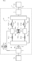
- a vibration path from an engine and a lock-up clutch (32) to an output hub (37) is divided into two parallel vibration paths B and C, and the two vibration paths B and C each have a pair of springs and a separate intermediate flange (36, 38) disposed between the pair of springs.
- a turbine (34) of the torque converter is coupled to the intermediate flange (36) of the vibration path B in order to make the natural frequencies of the two vibration paths different from each other, and the natural frequency of the intermediate flange (36) of the vibration path B is lower than the natural frequency of the intermediate flange (38) of the vibration path C.
- vibration from the engine is input to the two vibration paths B and C of the damper device.
- the vibration path B which includes the intermediate flange (36) coupled to the turbine (34)
- the phase of vibration between the intermediate flange (36) of the vibration path B and the output hub (37) is shifted by 180 degrees with respect to the phase of input vibration.
- vibration which is input to the vibration path C is transferred to the output hub (37) without causing a shift (deviation) of the phase.
- vibration of the output hub (37) can be damped by shifting the phase of vibration transferred from the vibration path B to the output hub (37) and the phase of vibration transferred from the vibration path C to the output hub (37) by 180 degrees.
- Patent Document 1 Published Japanese Translation of PCT Application No. 2012-506006 ( JP 2012-506006 A )
- the present disclosure provides a damper device that has an input element to which torque from an engine is transferred and an output element, including: a first intermediate element; a second intermediate element; a first elastic body that transfers torque between the input element and the first intermediate element; a second elastic body that transfers torque between the first intermediate element and the output element; a third elastic body that transfers torque between the input element and the second intermediate element; a fourth elastic body that transfers torque between the second intermediate element and the output element; and a fifth elastic body that transfers torque between the first intermediate element and the second intermediate element, in which: a natural frequency of the first intermediate element at a time when torque is transferred from the input element to the output element via all of the first to fifth elastic bodies is lower than a natural frequency of the second intermediate element at a time when torque is transferred from the input element to the output element via all of the first to fifth elastic bodies; and at least one of the first and second elastic bodies is disposed on a radially outer side of the third and fourth elastic bodies.
- the damper device by adjusting the rigidity of the fifth elastic body, it is possible to set the two natural frequencies of the entire damper device easily and appropriately while keeping the equivalent rigidity of the damper device appropriate and suppressing an increase in weights (moments of inertia) of the first and second intermediate elements. Furthermore, the natural frequency of the first intermediate element can be further reduced by increasing the moment of inertia of the first intermediate element by disposing at least one of the first and second elastic bodies corresponding to the first intermediate element, which has a natural frequency that is lower than that of the second intermediate element, on the radially outer side of the third and fourth elastic bodies. As a result, the vibration damping performance of the damper device can be improved well.
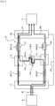
- FIG. 1 is a schematic diagram illustrating a starting device 1 that includes a damper device 10 according to the present disclosure.
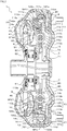
- FIG. 2 is a sectional view illustrating the starting device 1.
- the starting device 1 illustrated in the drawings is mounted on a vehicle that includes an engine (in the present embodiment, an internal combustion engine) EG that serves as a motor.
- an engine in the present embodiment, an internal combustion engine
- the starting device 1 includes: a front cover 3 coupled to a crankshaft of the engine EG; a pump impeller (input-side fluid transmission element) 4 fixed to the front cover 3; a turbine runner (output-side fluid transmission element) 5 that is coaxially rotatable with the pump impeller 4; a damper hub 7 that serves as a power output member coupled to the damper device 10 and fixed to an input shaft IS of a transmission (power transfer device) TM that is an automatic transmission (AT), a continuously variable transmission (CVT), a dual clutch transmission (DCT), a hybrid transmission, or a speed reducer; a lock-up clutch 8; and so forth.
- a transmission power transfer device
- TM that is an automatic transmission (AT), a continuously variable transmission (CVT), a dual clutch transmission (DCT), a hybrid transmission, or a speed reducer
- a lock-up clutch 8 and so forth.
- the term “axial direction” basically indicates the direction of extension of a center axis CA (axis; see FIG. 4 ) of the starting device 1 and the damper device 10.
- the term “radial direction” basically indicates the radial direction of a rotational element such as the starting device 1 or the damper device 10, that is, the direction of extension of a line that extends in directions (radial directions) that are orthogonal to the center axis CA from the center axis CA of the starting device 1 or the damper device 10.
- the term “circumferential direction” basically indicates the circumferential direction of a rotary element such as the starting device 1 or the damper device 10, that is, the direction along the rotational direction of such a rotary element.
- the pump impeller 4 has a pump shell 40 tightly fixed to the front cover 3 and a plurality of pump blades 41 disposed on the inner surface of the pump shell 40.
- the turbine runner 5 has a turbine shell 50 and a plurality of turbine blades 51 disposed on the inner surface of the turbine shell 50.
- the inner peripheral portion of the turbine shell 50 is fixed to a turbine hub 52 via a plurality of rivets.
- the turbine hub 52 is rotatably supported by the damper hub 7. Movement of the turbine hub 52 (turbine runner 5) in the axial direction of the starting device 1 is restricted by the damper hub 7 and a snap ring mounted to the damper hub 7.
- the pump impeller 4 and the turbine runner 5 face each other.
- a stator 6 is disposed between and coaxially with the pump impeller 4 and the turbine runner 5.
- the stator 6 adjusts a flow of working oil (working fluid) from the turbine runner 5 to the pump impeller 4.
- the stator 6 has a plurality of stator blades 60.
- the rotational direction of the stator 6 is set to only one direction by a one-way clutch 61.
- the pump impeller 4, the turbine runner 5, and the stator 6 form a torus (annular flow passage) that allows circulation of working oil, and function as a torque converter (fluid transmission apparatus) with a torque amplification function. It should be noted, however, that the stator 6 and the one-way clutch 61 may be omitted from the starting device 1, and that the pump impeller 4 and the turbine runner 5 may function as a fluid coupling.
- the lock-up clutch 8 can establish and release lock-up in which the front cover 3 and the damper hub 7 are coupled to each other via the damper device 10.
- the lock-up clutch 8 is constituted as a hydraulic single-plate clutch, and has a lock-up piston (power input member) 80 disposed inside the front cover 3 and in the vicinity of the inner wall surface of the front cover 3 on the engine EG side and fitted so as to be movable in the axial direction with respect to the damper hub 7.
- a friction material 88 is affixed to a surface of the lock-up piston 80 on the outer peripheral side and on the front cover 3 side.
- a lock-up chamber (engagement oil chamber) 85 is defined between the lock-up piston 80 and the front cover 3.
- the lock-up chamber 85 is connected to a hydraulic control device (not illustrated) via a working oil supply passage and an oil passage formed in the input shaft IS.
- a hydraulic multi-plate clutch that includes at least one friction engagement plate (a plurality of friction materials) may be adopted as the lock-up clutch 8.
- a clutch drum or a clutch hub of the hydraulic multi-plate clutch functions as the power input member.
- the damper device 10 damps vibration between the engine EG and the transmission TM.
- the damper device 10 includes, as rotary elements (rotary members, i.e. rotary mass bodies) that rotate coaxially relative to each other, a drive member (input element) 11, a first intermediate member (first intermediate element) 12, a second intermediate member (second intermediate element) 14, and a driven member (output element) 16.
- the damper device 10 further includes, as torque transfer elements (torque transfer elastic bodies): a plurality of (e.g. two in the present embodiment) first outer springs (first elastic bodies) SP11 disposed between the drive member 11 and the first intermediate member 12 to transfer rotational torque (torque in the rotational direction); a plurality of (e.g.
- second outer springs (second elastic bodies) SP12 disposed between the first intermediate member 12 and the driven member 16 to transfer rotational torque
- linear coil springs made of a metal material spirally wound so as to have an axis that extends straight when no load is applied are adopted as the first and second outer springs SP11 and SP12, the first and second inner springs SP21 and SP22, and the intermediate springs SPm. Consequently, a hysteresis due to a friction force generated between the springs which transfer torque and the rotary elements, that is, the difference between torque output when torque input to the drive member 11 is increasing and torque output when torque input to the drive member 11 is decreasing, can be reduced by expanding and contracting the springs SP11 to SPm along the axes more appropriately than the case where arc coil springs are used.
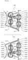
- the first outer springs SP 11, the second outer springs SP12, and the intermediate springs SPm are arranged side by side in the order of SP11, SP12, SPm, SP11, SP12, and SPm, for example, along the circumferential direction of the damper device 10 (first intermediate member 12), and disposed in the outer peripheral region in the fluid transmission chamber 9 in proximity to the outer periphery of the starting device 1.
- the intermediate springs SPm side by side with the first and second outer springs SP11 and SP12 on the outer peripheral side along the circumferential direction, it is possible to secure the torsional angle (stroke) between the first and second outer springs SP11 and SP12 and the intermediate springs SPm well.
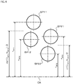
- the attachment radius r SP11 , r SP12 , r SP21 , or r SP22 may be the distance between the center axis CA and a point (e.g. the center or an end portion in the axial direction) determined in advance on the axis of the springs SP11, SP12, SP21, or SP22.
- first and second outer springs SP11 and SP12 are arranged on the same circumference so that the attachment radius r SP11 and the attachment radius r SP12 are equal to each other, and the axis of the first outer springs SP11 and the axis of the second outer springs SP12 are included in one plane that is orthogonal to the center axis CA.
- the first and second inner springs SP21 and SP22 are arranged on the same circumference so that the attachment radius r SP21 and the attachment radius r SP22 are equal to each other, and the axis of the first inner springs SP21 and the axis of the second inner springs SP22 are included in one plane that is orthogonal to the center axis CA.
- the first and second inner springs SP21 and SP22 are disposed on the radially inner side of the first and second outer springs SP11 and SP12 so as to overlap the first and second outer springs SP11 and SP12 in the axial direction as seen in the radial direction. Consequently, it is possible to make the damper device 10 compact in the radial direction, and to shorten the axial length of the damper device 10.
- the attachment radius r SP11 from the center axis CA to the axis of the first outer springs SP11 and the attachment radius r SP12 from the center axis CA to the axis of the second outer springs SP12 may be different from each other.
- the attachment radius r SP21 from the center axis CA to the axis of the first inner springs SP21 and the attachment radius r SP22 from the center axis CA to the axis of the second inner springs SP22 may be different from each other.
- the axes of the springs SP11, SP12, SP21, and SP22 may be included in one plane that is orthogonal to the center axis CA, and at least one of the axes of the springs SP11, SP12, SP21, and SP22 may not be included in the one plane.
- the rigidity, that is, the spring constant, of the first outer springs SP11 is defined as “k 11 "
- the rigidity, that is, the spring constant, of the second outer springs SP12 is defined as “k 12 "
- the rigidity, that is, the spring constant, of the first inner springs SP21 is defined as “k 21 "
- the rigidity, that is, the spring constant, of the second inner springs SP22 is defined as "k 22 ".
- the spring constants k 11 , k 12 , k 21 , and k 22 are selected such that the relations k 11 ⁇ k 21 and k 11 /k 21 ⁇ k 12 /k 22 are met.
- the spring constants k 11 , k 12 , k 21 , and k 22 meet the relations k 11 /k 21 ⁇ k 12 /k 22 and k 11 ⁇ k 12 ⁇ k 22 ⁇ k 21 . That is, the smaller one (k 11 ) of the spring constants k 11 and k 12 of the first and second outer springs SP11 and SP12 is smaller than the smaller one (k 22 ) of the spring constants k 21 and k 22 of the first and second inner springs SP21 and SP22.
- the rigidity that is, the spring constant
- the spring constants k 11 , k 12 , k 21 , k 22 , and k m meet the relation k 11 ⁇ k m ⁇ k 12 ⁇ k 22 ⁇ k 21 .
- the drive member 11 of the damper device 10 includes: an annular first plate member (first input member) 111 fixed to the lock-up piston 80 of the lock-up clutch 8; an annular second plate member (second input member) 112 rotatably supported (aligned) by the damper hub 7 and coupled so as to be rotatable together with the first plate member 111; and an annular third plate member (third input member) 113 disposed in more proximity to the turbine runner 5 than the second plate member 112 and coupled (fixed) to the second plate member 112 via a plurality of rivets (couplers) 125.
- the drive member 11 that is, the first, second, and third plate members 111, 112, and 113, rotates together with the lock-up piston 80, and the front cover 3 (engine EG) and the drive member 11 of the damper device 10 are coupled to each other through engagement of the lock-up clutch 8.
- the first plate member 111 has: an annular fixed portion 111a fixed to the inner surface (a surface to which the friction material 88 is not affixed) of the lock-up piston 80 on the outer peripheral side via a plurality of rivets; a short tubular portion 111b that extends in the axial direction from the outer peripheral portion of the fixed portion 111a; a plurality of (e.g.
- first abutment portions spring abutment portions (first abutment portions) 111c that extend radially outward at intervals (equal intervals) in the circumferential direction from the free end portion of the tubular portion 111b and that extend in the axial direction away from the fixed portion 111a; and a plurality of (e.g. twelve in the present embodiment) engagement projecting portions 111e that extend in the axial direction from the free end portion of the tubular portion 111b at intervals in the circumferential direction.
- the lock-up piston 80 to which the first plate member 111 is fixed is rotatably supported by a cylindrical first support portion 71 formed on the damper hub 7.
- the second plate member 112 is constituted as an annular plate-like member, disposed in more proximity to the lock-up piston 80 than the third plate member 113, and rotatably supported by a cylindrical second support portion 72 formed on the damper hub 7.
- the second support portion 72 of the damper hub 7 is formed as shifted in the axial direction of the damper device 10 from the first support portion 71 so as to be in more proximity to the turbine runner 5 than the first support portion 71.
- the second support portion 72 has an outside diameter that is larger than that of the first support portion 71, and is provided on the radially outer side of the first support portion 71.
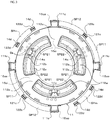
- the second plate member 112 has: a plurality of (e.g. three in the present embodiment) spring housing windows 112w (see FIGS. 3 and 5 ) that extend arcuately and that are disposed at intervals (at equal intervals) in the circumferential direction; a plurality of (e.g. three in the present embodiment) spring support portions 112a that extend along the inner peripheral edges of the respective spring housing windows 112w and that are arranged at intervals (equal intervals) in the circumferential direction; a plurality of (e.g.
- spring support portions 112b that extend along the outer peripheral edges of the respective spring housing windows 112w and that are arranged at intervals (equal intervals) in the circumferential direction to face the respective spring support portions 112a in the radial direction of the second plate member 112; and a plurality of (e.g. three in the present embodiment) spring abutment portions (second abutment portions) 112c.
- the plurality of spring abutment portions 112c of the second plate member 112 are provided such that each spring abutment portion 112c is interposed between the spring housing windows 112w (spring support portions 112a and 112b) which are adjacent to each other along the circumferential direction.
- engagement recessed portions 112e are formed at the outer peripheral portion of the second plate member 112 at intervals in the circumferential direction.
- the engagement recessed portions 112e are fitted with the respective engagement projecting portions 111 of the first plate member 111 with backlash in the radial direction.
- the first and second plate members 111 and 112 are relatively movable in the radial direction with the engagement projecting portions 111e fitted with the engagement recessed portions 112e.
- spring support portions 113b that extend along the outer peripheral edges of the respective spring housing windows and that are arranged at intervals (equal intervals) in the circumferential direction to face the respective spring support portions 113a in the radial direction of the third plate member 113; and a plurality of (e.g. three in the present embodiment) spring abutment portions (third abutment portions) 113c.
- the plurality of spring abutment portions 113c of the third plate member 113 are provided such that each spring abutment portion 113c is interposed between the spring support portions 113a and 113b (spring housing windows) which are adjacent to each other along the circumferential direction.
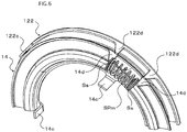
- the first intermediate member 12 includes an elastic body support member 121 and a coupling member 122.
- the elastic body support member 121 is formed in an annular shape so as to support (guide) the outer peripheral portions of the first and second outer springs SP11 and SP12, the side portions (right side portions in FIG. 2 ) of the first and second outer springs SP11 and SP12 on the lock-up piston 80 side (engine EG side), and the outer peripheral side of the side portions of the first and second outer springs SP11 and SP12 on the turbine runner 5 side (transmission TM side).
- the elastic body support member 121 is rotatably supported (aligned) in the radial direction by the tubular portion 111b of the first plate member 111 of the drive member 11, and disposed in the outer peripheral region in the fluid transmission chamber 9.
- the elastic body support member 121 has a plurality of (e.g. two at intervals of 180° in the present embodiment) spring abutment portions 121c disposed at intervals in the circumferential direction.
- the spring abutment portions 121c extend in the axial direction from the side portion of the elastic body support member 121 on the lock-up piston 80 side toward the turbine runner 5.
- the coupling member 122 which constitutes the first intermediate member 12 has: an annular fixed portion (annular portion) 122a fixed to the turbine shell 50 of the turbine runner 5 by welding, for example; a plurality of (e.g. two at intervals of 180° in the present embodiment) spring abutment portions (first spring abutment portions) 122c that extend in the axial direction from the outer peripheral portion of the fixed portion 122a at intervals in the circumferential direction; a plurality of (e.g.
- second spring abutment portions 122d that extend in the axial direction from the outer peripheral portion of the fixed portion 122a between the spring abutment portions 122c; and a support portion 122s in a short cylindrical shape that extends in the axial direction from the inner peripheral portion of the fixed portion 122a toward the same side as the spring abutment portions 122c and 122d extend.
- the plurality of second spring abutment portions 122d of the coupling member 122 are formed symmetrically with respect to the axis of the coupling member 122 such that two (a pair of) second spring abutment portions 122d are proximate to each other (see FIG. 3 ).
- the two second spring abutment portions 122d which are paired with each other are arranged in the circumferential direction at an interval that matches the natural length of the intermediate springs SPm, for example.
- the second intermediate member 14 has: an annular supported portion (annular portion) 14a; a plurality of (e.g. three at intervals of 120° in the present embodiment) spring abutment portions (first spring abutment portions) 14c that extend in the axial direction from the inner peripheral portion of the supported portion 14a at intervals in the circumferential direction; and a plurality of (e.g. four in the present embodiment) second spring abutment portions 14d that extend in the axial direction from the outer peripheral portion of the supported portion 14a toward the same side as the spring abutment portions 14c extend.
- first spring abutment portions first spring abutment portions
- second spring abutment portions 14d that extend in the axial direction from the outer peripheral portion of the supported portion 14a toward the same side as the spring abutment portions 14c extend.
- the second intermediate member 14 is rotatably supported by the coupling member 122 of the first intermediate member 12 which is fixed to the turbine runner 5, and the supported portion 14a of the second intermediate member 14 is positioned between the third plate member 113 of the drive member 11 and the turbine runner 5 in the axial direction.
- the supported portion 14a of the second intermediate member 14 is formed with a recessed portion with which the support portion 122s of the coupling member 122 is fitted, and the second intermediate member 14 is rotatably supported by the support portion 122s.
- movement of the second intermediate member 14 toward the turbine runner 5 is restricted with the supported portion 14a of the second intermediate member 14 abutting against the distal end of the support portion 122s.
- a plurality of movement restriction projecting portions 113s are formed at the outer peripheral portion of the third plate member 113 at intervals in the circumferential direction.
- the plurality of movement restriction projecting portions 113s project from the surface on the turbine runner 5 side toward the second intermediate member 14.
- movement of the second intermediate member 14 in the direction away from the turbine runner 5 is restricted with the supported portion 14a of the second intermediate member 14 abutting against the movement restriction projecting portions 113s of the third plate member 113.
- the driven member 16 is constituted as an annular plate-like member. As illustrated in FIG. 2 , the driven member 16 is disposed between the second plate member 112 and the third plate member 113 of the drive member 11 in the axial direction, and fixed to the damper hub 7 (in the present embodiment, the second support portion 72) via rivets. Consequently, the driven member 16 is rotated together with the damper hub 7.
- the driven member 16 has: a plurality of (e.g. three in the present embodiment) spring housing windows that extend arcuately and that are disposed at intervals (equal intervals) in the circumferential direction; a plurality of (e.g.
- inner spring abutment portions inner abutment portions 16ci formed at intervals in the circumferential direction in proximity to the inner peripheral edge of the driven member 16; and a plurality of (e.g. four in the present embodiment) outer spring abutment portions (outer abutment portions) 16co that are arranged at intervals (equal intervals) in the circumferential direction on the radially outer side with respect to the plurality of inner spring abutment portions 16ci and that extend in the axial direction from the turbine runner 5 side toward the lock-up piston 80.
- the plurality of inner spring abutment portions 16ci of the driven member 16 are provided such that each inner spring abutment portion 16ci is interposed between the spring housing windows which are adjacent to each other along the circumferential direction.
- each first outer spring SP11 abuts against a corresponding one of the spring abutment portions 111c of the drive member 11
- a second end portion (end portion on the second outer spring SP12 side in FIG. 3 ) of each first outer spring SP11 abuts against a corresponding one of the spring abutment portions 121c and a corresponding one of the spring abutment portions 122c of the first intermediate member 12.
- each second outer spring SP12 abuts against a corresponding one of the spring abutment portions 121c and a corresponding one of the spring abutment portions 122c of the first intermediate member 12, and a second end portion (end portion on the intermediate spring SPm side in FIG. 3 ) of each second outer spring SP12 abuts against a corresponding one of the spring abutment portions 111c of the drive member 11.
- the plurality of spring support portions 112a of the second plate member 112 support (guide) the side portions of the associated first and second inner springs SP21 and SP22 (one each) on the lock-up piston 80 side from the inner peripheral side.
- the plurality of spring support portions 112b support (guide) the side portions of the associated first and second inner springs SP21 and SP22 on the lock-up piston 80 side from the outer peripheral side.
- the plurality of spring support portions 113a of the third plate member 113 support (guide) the side portions of the associated first and second inner springs SP21 and SP22 (one each) on the turbine runner 5 side from the inner peripheral side.
- the plurality of spring support portions 113b support (guide) the side portions of the associated first and second inner springs SP21 and SP22 on the turbine runner 5 side from the outer peripheral side. That is, the first and second inner springs SP21 and SP22 are supported by the spring support portions 112a and 112b of the second plate member 112 and the spring support portions 113a and 113b of the third plate member 113, which constitute the drive member 11, such that one first inner spring SP21 and one second inner spring SP22 are paired (act in series with each other) and such that the first and second inner springs SP21 and SP22 are arranged alternately in the circumferential direction (circumferential direction of the second intermediate member 14).
- the spring abutment portions 112c of the second plate member 112 are each provided between the first and second inner springs SP21 and SP22, which are supported by different spring housing windows 112w (spring support portions 112a, 112b, 113a, and 113b) and which are not paired (do not act in series with each other), so as to abut against the end portions of such first and second inner springs SP21 and SP22 in the circumferential direction.
- the spring abutment portions 113c of the third plate member 113 are each provided between the first and second inner springs SP21 and SP22, which are supported by different spring support portions 112a, 112b, 113a, and 113b (spring housing windows) (which are not paired), so as to abut against the end portions of such first and second inner springs SP21 and SP22 in the circumferential direction.
- spring support portions 112a, 112b, 113a, and 113b spring housing windows
- each second inner spring SP22 abuts against a corresponding one of the spring abutment portions 14c of the second intermediate member 14, and a second end portion of each second inner spring SP22 abuts against a corresponding one of the spring abutment portions 112c and a corresponding one of the spring abutment portions 113c of the drive member 11.
- spring seats Ss may be disposed between each spring abutment portion 14c and the second end portion of the corresponding first inner spring SP21 and between the spring abutment portion 14c and the first end portion of the corresponding second inner spring SP22.
- each first inner spring SP21 also abuts against the corresponding inner spring abutment portion 16ci of the driven member 16
- the second end portion of each second inner spring SP22 also abuts against the corresponding inner spring abutment portion 16ci of the driven member 16.
- the driven member 16 is coupled to the drive member 11 via the plurality of first inner springs SP21, the second intermediate member 14, and the plurality of second inner springs SP22.
- each intermediate spring SPm is supported from both sides by the pair of second spring abutment portions 122d of the first intermediate member 12 (coupling member 122), and supported from both sides by the pair of second spring abutment portions 14d of the second intermediate member 14. Consequently, the first intermediate member 12 and the second intermediate member 14 are coupled to each other via the plurality of intermediate springs SPm.
- spring seats Ss are disposed between the end portions of the intermediate springs SPm and the second spring abutment portions 14d and 122d.
- the first stopper 21 is constituted from: a plurality of stopper portions 122x that extend in the axial direction from the coupling member 122, which constitutes the first intermediate member 12, toward the lock-up piston 80 at intervals in the circumferential direction; and a plurality of notch portions 161x formed in the outer peripheral portion of the driven member 16 at intervals in the circumferential direction to extend arcuately.
- the stopper portions 122x of the first intermediate member 12 are inserted through any of a plurality of arcuate slits 14v formed in the outer peripheral portion of the supported portion 14a of the second intermediate member 14 at intervals in the circumferential direction, and disposed in the respective notch portions 161x of the driven member 16 so as not to abut against the wall surfaces of the driven member 16 which define the end portions of the notch portions 161x on both sides.
- each stopper portion 122x of the coupling member 122 and one of the wall surfaces which define the end portions of the notch portion 161x on both sides abut against each other along with relative rotation between the first intermediate member 12 and the driven member 16
- relative rotation between the first intermediate member 12 and the driven member 16 and deflection of the second outer springs SP12 are restricted.
- the stopper portions 122x of the first intermediate member 12 and the wall surfaces of the second intermediate member 14 which define the end portions of the slits 14v on both sides do not abut against each other during a period before relative rotation between the drive member 11 and the driven member 16 is restricted by the third stopper 23.
- the stopper portions 162x of the driven member 16 are inserted through any of a plurality of arcuate slits 113v formed in the outer peripheral portion of the third plate member 113 of the drive member 11 at intervals in the circumferential direction, and disposed in the respective slits 14x of the second intermediate member 14 so as not to abut against the wall surfaces of the second intermediate member 14 which define the end portions of the slits 14x on both sides.
- the third stopper 23 is constituted from: collars mounted to the plurality of rivets which couple the second and third plate members 112 and 113, which constitute the drive member 11, to each other; and a plurality of notch portions 163x formed in the driven member 16 at intervals in the circumferential direction to extend arcuately.
- the plurality of rivets 125 and the collars are disposed in the respective notch portions 163x of the driven member 16 so as not to abut against the wall surfaces of the driven member 16 which define the end portions of the notch portions 163x on both sides.
- first and second outer springs SP11 and SP12 are disposed such that the entire first and second outer springs SP11 and SP12 are positioned on the radially outer side with respect to the first and second inner springs SP21 and SP22.
- the first and second outer springs SP11 and SP12 which are low in rigidity and relatively light in weight, are disposed on the outer peripheral side of the damper device 10
- the first and second inner springs SP21 and SP22 which are high in rigidity and relatively heavy in weight, are disposed on the center axis CA side of the damper device 10. Consequently, it is possible to reduce the hysteresis of the entire damper device 10 by reducing a friction force generated between the springs SP11, SP12, SP21, and SP22 and the associated rotary elements because of a centrifugal force.
- the damper device 10 further includes the coupling member 122 which is fixed to the turbine runner 5 and has the spring abutment portions 122c which are each provided between the first and second outer springs SP11 and SP12, which are adjacent to each other, so as to abut against the end portions of such first and second outer springs SP11 and SP12 in the circumferential direction. Consequently, it is possible to couple the first intermediate member 12 to both the first and second outer springs SP11 and SP12, which are disposed on the radially outer side, and to couple the first intermediate member 12 to the turbine runner 5 while suppressing an increase in axial length of the damper device 10.
- the substantial moment of inertia of the first intermediate member 12 (the total of the moments of inertia of the elastic body support member 121, the coupling member 122, the turbine runner 5, and so forth) can be further increased.
- both the spring abutment portions 121c of the elastic body support member 121 and the spring abutment portions 122c of the coupling member 122 to abut against the end portions of the first and second outer springs SP11 and SP12, it is possible to smoothly expand and contract the first and second outer springs SP11 and SP12.
- the first outer springs (first elastic bodies) SP11 transfer rotational torque from the drive member 11 to the first intermediate member 12, and the second outer springs (second elastic bodies) SP12 transfer rotational torque from the first intermediate member 12 to the driven member 16.
- the first inner springs (third elastic bodies) SP21 transfer rotational torque from the drive member 11 to the second intermediate member 14, and the second inner springs (fourth elastic bodies) SP22 transfer rotational torque from the second intermediate member 14 to the driven member 16.
- the damper device 10 has, as torque transfer paths between the drive member 11 and the driven member 16, the first torque transfer path P1 which includes the first outer springs SP11, the first intermediate member 12, and the second outer springs SP12 and the second torque transfer path P2 which includes the first inner springs SP21, the second intermediate member 14, and the second inner springs SP22.
- the spring constants k 11 , k 12 , k 21 , and k 22 of the first and second outer springs SP11 and SP12 and the first and second inner springs SP21 and SP22 meet the relation k 11 ⁇ k 12 ⁇ k 22 ⁇ k 21 . Therefore, when torque is transferred to the drive member 11 during a period before input torque reaches the torque T1 during establishment of lock-up, as illustrated in FIG. 7 , the second intermediate member 14 is (slightly) twisted with respect to the first intermediate member 12 toward the advancing direction side (toward the downstream side) in the rotational direction (the rotational direction at the time when the vehicle travels forward).
- torque is transferred from the drive member 11 to the driven member 16 via the first, second, and third torque transfer paths P1, P2, and P3. More particularly, while deflection of all of the first and second outer springs SP11 and SP12, the first and second inner springs SP21 and SP22, and the intermediate springs SPm is allowed, rotational torque from the first outer springs SP11 and rotational torque from the first inner springs SP21, the second intermediate member 14, and the intermediate springs SPm are transferred to the second outer springs SP12. In addition, rotational torque from the first inner springs SP21 is transferred to the second inner springs SP22.
- the first outer springs SP11 and the first inner springs SP21 act in parallel with each other to damp (absorb) fluctuations in torque transferred to the drive member 11 since torque input to the drive member 11 reaches the torque T1 described above until the input torque reaches the torque T2 described above to cause the third stopper 23 to operate.
- damper device 10 As discussed above, while deflection of all of the first and second outer springs SP11 and SP12, the first and second inner springs SP21 and SP22, and the intermediate springs SPm is allowed, torque (average torque) is transferred between the drive member 11 and the driven member 16 via all of the springs SP11 to SPm.
- the inventors diligently studied and analyzed the damper device 10 which had complicated torque transfer paths which were neither series nor parallel. As a result, the inventors found that such a damper device 10 had two natural frequencies for the entire device while deflection of all of the springs SP11 to SPm is allowed.
- the damper device 10 in addition, when resonance (in the present embodiment, resonance of the first intermediate member 12 at the time when the first and second intermediate members 12 and 14 are vibrated in phase with each other) at the lower one of the two natural frequencies (a natural frequency on the low-rotation side (low-frequency side) is generated in accordance with the frequency of vibration transferred to the drive member 11, the phase of vibration transferred from the second outer springs SP12 to the driven member 16 and the phase of vibration transferred from the second inner springs SP22 to the driven member 16 are shifted from each other.
- resonance in the present embodiment, resonance of the first intermediate member 12 at the time when the first and second intermediate members 12 and 14 are vibrated in phase with each other
- the lower one of the two natural frequencies a natural frequency on the low-rotation side (low-frequency side)
- ⁇ 1 is the torsional angle of the drive member 11
- ⁇ 21 is the torsional angle of the first intermediate member 12
- ⁇ 22 is the torsional angle of the second intermediate member 14
- ⁇ 3 is the torsional angle of the driven member 16.
- k 1 is the synthetic spring constant of the plurality of first outer springs SP11 which are provided between the drive member 11 and the first intermediate member 12 to act in parallel with each other
- k 2 is the synthetic spring constant of the plurality of second outer springs SP12 which are provided between the first intermediate member 12 and the driven member 16 to act in parallel with each other
- k 3 is the synthetic spring constant of the plurality of first inner springs SP21 which are provided between the drive member 11 and the second intermediate member 14 to act in parallel with each other
- k 4 is the synthetic spring constant of the plurality of second inner springs SP22 which are provided between the second intermediate member 14 and the driven member 16 to act in parallel with each other
- k 5 is the synthetic spring constant (rigidity) of the plurality of intermediate springs SPm which are provided between the first intermediate member 12 and the second intermediate member 14 to act in parallel with each other
- k R is the rigidity, that is, the spring constant, of the transmission TM, a drive shaft, etc.
- the inventors then focused on the fact that, if the vibration amplitude ⁇ 3 of the driven member 16 in the formula (4) became zero, no vibration was transferred in theory to the transmission TM, the drive shaft, etc. in a stage subsequent to the driven member 16 as vibration from the engine EG is damped by the damper device 10.
- the inventors obtained a conditional expression indicated by the following formula (5) by solving the identity of the formula (4) for the vibration amplitude ⁇ 3 and setting ⁇ 3 to zero.
- vibrations from the engine EG transferred from the drive member 11 to the driven member 16 via the first, second, and third torque transfer paths P1, P2, and P3 cancel out each other, and the vibration amplitude ⁇ 3 of the driven member 16 becomes zero in theory.
- ⁇ 2 k 5 ⁇ k 1 + k 3 ⁇ k 2 + k 4 + k 1 k 2 k 3 + k 1 k 2 k 4 + k 1 k 3 k 4 + k 2 k 3 k 4 J 21 k 3 k 4 + J 22 k 1 k 2
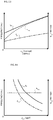
- an antiresonance point A at which the vibration amplitude ⁇ 3 (torque fluctuations) of the driven member 16 becomes zero in theory as indicated in FIG. 8 may be set because the phase of vibration transferred from the second outer springs SP12 to the driven member 16 and the phase of vibration transferred from the second inner springs SP22 to the driven member 16 are shifted by 180 degrees (inverted) from each other through generation of resonance at the lower one of the two natural frequencies so that the vibrations cancel out each other.
- FIG. 8 indicates an example of the relationship between the rotational speed of the engine EG and the vibration amplitude (torque fluctuations) in theory (under the assumption that no hysteresis is provided) of the driven members of the damper device according to the present disclosure and a damper device from which the intermediate springs SPm have been omitted (the damper device described in Patent Document 1; hereinafter referred to as a "damper device according to a comparative example").
- both the amplitudes ⁇ 21 and ⁇ 22 are not zero.
- the determinant of the square matrix on the left side of the formula (9) is zero, and a conditional expression of the following formula (10) must be met.
- Such a formula (10) is a quadratic equation for the square value ⁇ 2 of two natural angular frequencies of the damper device 10.
- the two natural angular frequencies ⁇ 1 and ⁇ 2 of the damper device 10 are represented by the following formulas (11) and (12), and ⁇ 1 ⁇ ⁇ 2 is met.
- the frequency of resonance (resonance point R1) that causes the resonance point A, that is, the natural frequency of the first intermediate member 12 is defined as “f 21 "
- the frequency of resonance (resonance point R2) generated on the high-rotation side with respect to the antiresonance point A, that is, the natural frequency of the second intermediate member 14 is defined as "f 22 "
- the natural frequency f 21 on the low-rotation side (low-frequency side) is represented by the following formula (13)
- the natural frequency f 22 (f 22 > f 21 ) on the high-rotation side (high-frequency side) is represented by the following formula (14).
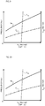
- FIGS. 9 to 14 indicate the mode of variations in the natural frequency f 21 , the frequency fa of the antiresonance point A, and the equivalent rigidity k eq at the time when only one of the synthetic spring constants k 1 , k 2 , k 3 , k 4 , and k 5 and the moments of inertia J 21 and J 22 of the first and second intermediate members 12 and 14 is varied while keeping the others of the parameters at constant values (fixed values).
- the equivalent rigidity k eq is increased steeply when the synthetic spring constant k 1 is increased slightly from a value adapted in advance, and decreased steeply when the synthetic spring constant k 1 is decreased slightly from the adapted value. That is, variations (variation gradient) in the equivalent rigidity k eq are very large with respect to variations in the synthetic spring constant k 1 of the first outer springs SP 11.
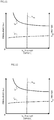
- the difference (fa - f 21 ) between the natural frequency f 21 and the frequency fa of the antiresonance point A corresponding to a certain synthetic spring constant k 5 becomes gradually larger as the synthetic spring constant k 5 becomes larger. Furthermore, in the case where only the synthetic spring constant k 5 of the intermediate springs SPm is varied, as illustrated in FIG. 13 , the equivalent rigidity k eq becomes higher as the synthetic spring constant k 5 is larger, and becomes gradually lower as the synthetic spring constant k 5 becomes smaller.
- the values of the spring constants k 11 , k 12 , k 21 , k 22 , and k m are determined so as to meet the relation k 11 ⁇ k m ⁇ k 12 ⁇ k 22 ⁇ k 21 discussed above.
- the spring constant k m of the intermediate springs SPm and the spring constants k 11 and k 12 of the first and second outer springs SP11 and SP12 are determined to be small such that the natural frequency f 21 on the low-rotation side and the frequency fa of the antiresonance point A is reduced more. Furthermore, the spring constants k 21 and k 22 of the first and second inner springs SP21 and SP22 are determined to be large such that the natural frequency f 21 on the low-rotation side is reduced more.
- the rotational speed (frequency) at which the phase of vibration transferred from the second outer springs SP12 to the driven member 16 and the phase of vibration transferred from the second inner springs SP22 to the driven member 16 are shifted by 180 degrees from each other can also be set to the low-rotation side.
- the rotational speed (frequency) at which the phase of vibration transferred from the second outer springs SP12 to the driven member 16 and the phase of vibration transferred from the second inner springs SP22 to the driven member 16 are shifted by 180 degrees from each other can also be set to the low-rotation side.
- the spring constants (synthetic spring constants) k 1 , k 2 , k 3 , k 4 , and k 5 and the moments of inertia J 21 and J 22 are preferably selected and set such that the frequency of resonance generated on the high-rotation side (high-frequency side) with respect to the antiresonance point A is higher. Consequently, it is possible to generate such resonance (resonance point R2) in the high-rotational speed range in which vibration does not easily become manifest, which further improves the vibration damping performance of the damper device 10 in the low-rotational speed range.
- the natural frequencies f 21 and f 22 are affected by both the moments of inertia J 21 and J 22 of the first and second intermediate members 12 and 14.
- the damper device 10 it is possible to easily shift resonance at the lower one of the two natural frequencies f 21 and f 22 to the low-rotation side, that is, the non-lock-up region, while suppressing an increase in weights of the first and second intermediate members 12 and 14, that is, the moments of inertia J 21 and J 22 , and to set the natural frequencies f 21 and f 22 and the frequency fa of the antiresonance point A easily and appropriately such that the vibrations cancel out each other at the driven member 16 better when the rotational speed of the drive member 11 is lower.
- the two natural frequencies f 21 and f 22 are affected by both the moments of inertia J 21 and J 22 of the first and second intermediate members 12 and 14.
- the natural frequency f 21 (resonance point R1) on the low-rotation side can be easily shifted to the lower-rotation side of the non-lock-up region compared to the damper device according to the comparative example described above while determining the frequency fa of the antiresonance point A as a value about a frequency fa' of the antiresonance point of the damper device according to the comparative example.
- the analysis conducted by the inventors has revealed that, by coupling vibrations of the first and second intermediate members 12 and 14 to each other by coupling the first and second intermediate members 12 and 14 to each other using the intermediate springs SPm, vibrations transferred from the first, second, and third torque transfer paths P1, P2, and P3 described above to the driven member 16 tend to cancel out each other, which may reduce the actual vibration amplitude of the driven member 16 around the antiresonance point A and decrease the difference in torque amplitude (torque fluctuations) between the second outer springs SP12 and the second inner springs SP22 (bring the torque amplitudes of the second outer springs SP12 and the second inner springs SP22 closer to each other).
- the frequency fa' of the antiresonance point in the damper device according to the comparative example is represented by the following formula (22).
- the vibration amplitude fa' of the antiresonance point in the damper device according to the comparative example is smaller than the frequency fa of the antiresonance point A in the damper device 10.
- the first and second outer springs SP11 and SP12 which have a spring constant (rigidity) that is smaller than that of the first and second inner springs SP21 and SP22 are disposed on the outer side of the first and second inner springs SP21 and SP22 in the radial direction of the damper device 10. Consequently, it is possible to increase the moment of inertia J 21 of the first intermediate member 12 and to lower the rigidity of the first and second outer springs SP11 and SP12, so that the natural frequency (f 21 ) of the first intermediate member 12 can be further lowered.
- the first and second outer springs SP11 and SP12 which have a low rigidity and a relatively light weight are disposed on the outer peripheral side of the damper device 10
- the first and second inner springs SP21 and SP22 which have a high rigidity and a relatively heavy weight are disposed on the center axis CA side of the damper device 10.
- the basic procedure for designing the damper device 10 under the assumption that no hysteresis is provided has been described so far.
- the frequency at which the phase of vibration transferred from the second outer springs SP12 to the driven member 16 is shifted by 180 degrees with respect to the phase of vibration transferred from the second inner springs SP22 to the driven member 16 may be shifted to the high-frequency side (high-rotation side) from the theoretical value because of the hysteresis.
- the frequency at which the vibration amplitude of the driven member 16 is minimized because vibration from the second outer springs SP12 and vibration from the second inner springs SP22 cancel out each other may also be shifted to the high-frequency side (high-rotation side).
- the inventors closely investigated the effect of the hysteresis on the phase inversion of vibration due to resonance at the natural frequency on the low-frequency side in the damper device 10 and the damper device according to the comparative example.
- the inventors first performed a simulation for a model of the damper device according to the comparative example in which the theoretical frequency fa' (see the formula (18) given above) of the antiresonance point is caused to generally coincide with a frequency ftag of resonance due to vibration of the entire damper device and the drive shaft of the vehicle (resonance due to vibration generated between the drive member and the drive shaft) to verify variations in phase of vibration due to resonance at the natural frequency f 21 ' on the low-frequency side.
- the simulation result for the damper device according to the comparative example is indicated by the broken line. It was revealed that, in the damper device according to the comparative example, as indicated in FIG.
- the damper device according to the comparative example may not damp resonance due to vibration of the entire damper device and the drive shaft of the vehicle well.
- the inventors further performed a simulation for a model of the damper device 10 in which the theoretical frequency fa (see the formula (6) given above) of the antiresonance point A is caused to generally coincide with the frequency ftag (the same value as with the comparative example) of resonance due to vibration of the entire damper device 10 and the drive shaft of the vehicle to verify variations in phase of vibration due to resonance at the natural frequency f 21 on the low-frequency side in the damper device 10.
- the simulation result for the damper device 10 is indicated by the solid line. As seen from the simulation results in FIG.
- the damper device 10 which includes the intermediate springs SPm, as discussed above, resonance at the natural frequency f 21 on the low-frequency side, that is, resonance of the first intermediate member 12, can be easily shifted to the low-frequency side by adjusting the moments of inertia J 21 and J 22 of the first and second intermediate members 12 and 14.
- the spring constants k 11 , k 12 , k 21 , and k 22 of the first and second outer springs SP11 and SP12 and the first and second inner springs SP21 and SP22 meet the relations k 11 ⁇ k 21 and k 11 /k 21 ⁇ k 12 /k 22 .
- the frequency fr at which the phase of vibration transferred from the second outer springs SP12 to the driven member 16 is shifted by 180 degrees with respect to the phase of vibration transferred from the second inner springs SP22 to the driven member 16 can be shifted to the low-frequency side (low-rotation side) with respect to the frequency ftag of vibration to be damped.
- the spring constants k 11 , k 12 , k 21 , and k 22 of the first and second outer springs SP11 and SP12 and the first and second inner springs SP21 and SP22 meet the relations k 11 /k 21 ⁇ k 12 /k 22 and k 11 ⁇ k 12 ⁇ k 22 ⁇ k 21 .
- torque (a part of average torque) is transferred from the second intermediate member 14 to the first intermediate member 12 via the third torque transfer path P3 which includes the intermediate springs SPm, which increases torque transferred by the second outer springs SP12 which are provided between the first intermediate member 12 and the driven member 16.
- the damper device 10 it is possible to further reduce a friction force generated between the first and second outer springs SP11 and SP12 and the rotary elements, that is, the hysteresis, because of a weight reduction of the first and second outer springs SP11 and SP12 due to the rigidity reduction, and to shift resonance at the natural frequency f 21 , that is, resonance of the first intermediate member 12, to the low-frequency side.
- a shift of the frequency fr described above to the high-frequency side due to the hysteresis can be reduced well.
- FIG. 16 illustrates the relationship among a torque distribution ratio ⁇ 1 of the first outer springs SP11 and the first inner springs SP21 to which torque is transferred from the drive member 11, a torque distribution ratio ⁇ 2 of the second outer springs SP12 and the second inner springs SP22 which transfer torque to the driven member 16, and the vibration damping performance of the damper device 10.
- the inventors also analyzed the relationship between the torque distribution ratios ⁇ 1 and ⁇ 2 and the vibration damping performance of the damper device 10 at the time when the torque T which was input to the drive member 11 was a predetermined value that is less than the torque T1 described above (when deflection of all of the springs SP11, SP12, SP21, SP22, and SPm was allowed).
- the inventors obtained through analysis a range in the region X in which the vibration damping performance was secured well while suppressing an increase in coil diameter or axial length of the springs SP11, SP12, SP21, SP22, and SPm, that is, an increase in size of the damper device 10.
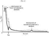
- FIG. 17 illustrates an example of the relationship between the rotational speed of the engine EG and the vibration amplitude (torque fluctuations) of the driven member of the damper device 10 and the damper device according to the comparative example, from which the intermediate springs SPm have been omitted, with the hysteresis taken into consideration.
- the solid line indicates the simulation result for the vibration amplitude (torque fluctuations) of the driven member of the damper device 10 with the hysteresis taken into consideration
- the broken line indicates the simulation result for the vibration amplitude (torque fluctuations) of the driven member of the damper device according to the comparative example with the hysteresis taken into consideration.
- a model of the damper device according to the comparative example used in the simulation was built by determining various specifications such that the theoretical frequency fa' of the antiresonance point generally coincided with the frequency ftag (the same value as with the damper device 10) of resonance due to vibration of the entire damper device and the drive shaft of the vehicle.
- the spring constant K 21 of the first inner springs SP21 is larger than the spring constant K 22 of the second inner springs SP22 (k 22 ⁇ k 21 ).
- the spring constant k m of the intermediate springs SPm may be determined to be smaller than the spring constants k 11 , k 12 , k 21 , and k 22 of the first and second outer springs SP11 and SP12 and the first and second inner springs SP21 and SP22. That is, as discussed above, the natural frequency f 21 on the low-rotation side (low-frequency side) and the frequency fa of the antiresonance point A are lower as the synthetic spring constant k 5 of the intermediate springs SPm is smaller (see FIG. 13 ).
- the natural frequency f 21 and the frequency fa can be made much smaller. Adopting such a configuration also makes it possible to set the start point of a rotational speed band in which one of vibration transferred from the second outer springs SP12 to the driven member 16 and vibration transferred from the second inner springs SP22 to the driven member 16 is used to cancel out at least a part of the other on the lower-rotation side.
- the rotational speed (frequency) at which the phase of vibration transferred from the second outer springs SP12 to the driven member 16 and the phase of vibration transferred from the second inner springs SP22 to the driven member 16 are shifted by 180 degrees from each other can also be set to the low-rotation side (low-frequency side).
- the spring constants k 11 , k 12 , k 21 , and k 22 of the first and second outer springs SP11 and SP12 and the first and second inner springs SP21 and SP22 preferably meet at least the relations k 11 ⁇ k 21 and k 11 /k 21 ⁇ k 12 /k 22 .
- the spring constant k m of the intermediate springs SPm may be determined to be larger than the spring constants k 11 , k 12 , k 21 , and k 22 of the first and second outer springs SP11 and SP12 and the first and second inner springs SP21 and SP22. That is, as discussed above, the difference (fa - f 21 ) between the natural frequency f 21 on the low-rotation side (low-frequency side) and the frequency fa of the antiresonance point A is larger as the synthetic spring constant k 5 of the intermediate springs SPm is larger (see FIG. 13 ).
- the spring constant (rigidity) k m of the intermediate springs SPm larger than the spring constants k 11 , k 12 , k 21 , and k 22 , it is possible to widen the rotational speed band in which one of vibration transferred from the second outer springs SP12 to the driven member 16 and vibration transferred from the second inner springs SP22 to the driven member 16 is used to cancel out at least a part of the other, that is, a range in which the vibration level of the driven member 16 may be lowered well, by increasing the difference from the difference (fa - f 21 ) between the natural frequency f 21 and the frequency fa.
- the spring constants k 11 , k 12 , k 21 , and k 22 of the first and second outer springs SP11 and SP12 and the first and second inner springs SP21 and SP22 are preferably adjusted such that the natural frequency f 21 and the frequency fa of the antiresonance point A are further reduced and the difference (fa - f 21 ) therebetween is more increased.
- the damper device 10 may further include at least one torque transfer path provided in parallel with the first and second torque transfer paths P1 and P2, for example, in addition to the first, second, and third torque transfer paths P1, P2, and P3. Moreover, at least one of the first and second torque transfer paths P1 and P2, for example, of the damper device 10 may be additionally provided with at least one set of an intermediate member and springs (elastic bodies).
- the frequency fa of the antiresonance point A described above may be caused to coincide with a frequency fs of shudder generated when the slip control is executed, or may be set to a value that is close to the frequency fs of the shudder. Consequently, it is possible to reduce shudder generated when the slip control is executed.
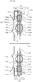
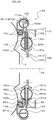
- FIG. 18 is a sectional view illustrating another damper device 10X according to the present disclosure. Constituent elements of the damper device 10X that are identical to the elements of the damper device 10 discussed above are given the same numerals to omit redundant descriptions.
- a drive member 11X of the damper device 10X illustrated in FIG. 18 includes: an annular coupling member 110 fixed to the lock-up piston of the lock-up clutch; an annular first plate member (first input member) 111X rotatably supported (aligned) by the damper hub, for example, and coupled so as to rotate together with the coupling member 110; and an annular second plate member (second input member) 112X disposed in more proximity to the turbine runner 5 than the first plate member 111X and coupled (fixed) to the first plate member 111X via a plurality of rivets.
- the drive member 11X that is, the first and second plate members 111X and 112X, rotates together with the lock-up piston, and the front cover (engine EG) and the drive member 11X of the damper device 10 are coupled to each other through engagement of the lock-up clutch.
- the lock-up clutch is a hydraulic multi-plate clutch
- the coupling member 110 may be constituted as a clutch drum of the lock-up clutch.
- the first plate member 111X is constituted as an annular plate-like member, and disposed in more proximity to the lock-up piston 80 than the second plate member 112X.
- the first plate member 111X has a plurality of (e.g. three) inner spring housing windows 111wi, a plurality of (e.g. four) outer spring housing windows 111wo, a plurality of (e.g. three) spring support portions 1111, a plurality of (e.g. three) spring support portions 1112, a plurality of (e.g. four) spring support portions 1113, a plurality of (e.g. four) spring support portions 1114, a plurality of (e.g. three) inner spring abutment portions 111ci, and a plurality of (e.g. four) outer spring abutment portions 111co.
- the plurality of inner spring housing windows 111wi extend arcuately, and are disposed at intervals (equal intervals) in the circumferential direction in the inner peripheral portion of the first plate member 111X.
- the plurality of spring support portions 1111 extend along the inner peripheral edges of the respective inner spring housing windows 111wi, and are arranged at intervals (equal intervals) in the circumferential direction.
- the plurality of spring support portions 1112 extend along the outer peripheral edges of the respective inner spring housing windows 111wi, and are arranged at intervals (equal intervals) in the circumferential direction to face the respective spring support portions 1111 in the radial direction of the first plate member 111X.
- each inner spring abutment portion 111ci is interposed between the inner spring housing windows 111wi (spring support portions 1111 and 1112) which are adjacent to each other along the circumferential direction.
- the plurality of outer spring housing windows 111wo extend arcuately, and are disposed at intervals in the circumferential direction in the outer peripheral portion of the first plate member 111X so as to be positioned on the radially outer side with respect to the inner spring housing windows 111wi.
- the plurality of spring support portions 1113 extend along the inner peripheral edges of the respective outer spring housing windows 111wo, and are arranged at intervals (equal intervals) in the circumferential direction.
- the plurality of spring support portions 1114 extend along the outer peripheral edges of the respective outer spring housing windows 111wo, and are arranged at intervals (equal intervals) in the circumferential direction to face the respective spring support portions 1113 in the radial direction of the first plate member 111X.
- each outer spring abutment portion 111co is interposed between the outer spring housing windows 111wo (spring support portions 1113 and 1114) which are adjacent to each other along the circumferential direction.
- the second plate member 112X is constituted as an annular plate-like member, and disposed in more proximity to the turbine runner 5 than the first plate member 111X.
- the second plate member 112X has a plurality of (e.g. three) inner spring housing windows 112wi, a plurality of (e.g. four) outer spring housing windows 112wo, a plurality of (e.g. three) spring support portions 1121, a plurality of (e.g. three) spring support portions 1122, a plurality of (e.g. four) spring support portions 1123, a plurality of (e.g. four) spring support portions 1124, a plurality of (e.g. three) inner spring abutment portions 112ci, and a plurality of (e.g. four) outer spring abutment portions 112co.
- the plurality of inner spring housing windows 112wi extend arcuately, and are disposed at intervals (equal intervals) in the circumferential direction in the inner peripheral portion of the second plate member 112X.
- the plurality of spring support portions 1121 extend along the inner peripheral edges of the respective inner spring housing windows 112wi, and are arranged at intervals (equal intervals) in the circumferential direction.
- the plurality of spring support portions 1122 extend along the outer peripheral edges of the respective inner spring housing windows 112wi, and are arranged at intervals (equal intervals) in the circumferential direction to face the respective spring support portions 1121 in the radial direction of the second plate member 112X.
- each inner spring abutment portion 112ci is interposed between the inner spring housing windows 112wi (spring support portions 1121 and 1122) which are adjacent to each other along the circumferential direction.
- each outer spring abutment portion 112co is interposed between the outer spring housing windows 112wo (spring support portions 1123 and 1124) which are adjacent to each other along the circumferential direction.
- a first intermediate member 12X of the damper device 10X includes: a plate-like annular member 121X disposed between the first and second plate members 111X and 112X of the drive member 11X in the axial direction; and a coupling member 122X fixed to the turbine runner 5.
- the annular member 121X has: a plurality of (e.g. two at intervals of 180° in the present embodiment) spring abutment portions 121c that extend radially inward from an annular outer peripheral portion at intervals in the circumferential direction; and a plurality of (e.g.
- second spring abutment portions 121d that extend radially inward from portions of the annular outer peripheral portion located between the spring abutment portions 121c which are adjacent to each other in the circumferential direction.
- the plurality of second spring abutment portions 121d are formed symmetrically with respect to the axis of the annular member 121X such that two (a pair of) second spring abutment portions 121d are proximate to each other.
- the two second spring abutment portions 121d which are paired with each other are arranged in the circumferential direction at an interval that matches the natural length of the intermediate springs SPm, for example.
- the coupling member 122X of the first intermediate member 12X has: an annular fixed portion fixed by welding, for example, to the turbine shell 50 of the turbine runner 5; and a plurality of projecting portions that extend in the axial direction from the outer peripheral portion of the fixed portion at intervals in the circumferential direction. As illustrated in FIG. 18 , the projecting portions of the coupling member 122X are fitted with respective recessed portions formed in the outer periphery of the annular member 121X from the turbine runner 5 side. Consequently, the outer peripheral portion of the annular member 121X and the coupling member 122X which is fixed to the turbine runner 5 are coupled so as to rotate together with each other.
- a second intermediate member 14X of the damper device 10X is an annular plate-like member rotatably supported (aligned) by the damper hub 7, for example, and has a natural frequency that is higher than that of the first intermediate member 12X and a moment of inertia that is smaller than that of the first intermediate member 12X.
- the second intermediate member 14X has: a plurality of (e.g. three) spring housing windows; a plurality of (e.g. three) spring abutment portions 14c disposed at intervals in the circumferential direction; a support portion 14s in a short tube shape that extends in the axial direction on the radially outer side with respect to the spring abutment portions 14c; and a plurality of (e.g. four) second spring abutment portions 14d that extend radially outward from the distal end of the support portion 14s away from the spring abutment portions 14c in the axial direction.
- the second spring abutment portions 14d are formed symmetrically with respect to the axis of the second intermediate member 14X such that two (a pair of) second spring abutment portions 14d are proximate to each other.
- the two second spring abutment portions 14d which are paired with each other are arranged in the circumferential direction at an interval that matches the natural length of the intermediate springs SPm, for example.
- a driven member 16X of the damper device 10X is constituted as an annular plate-like member. As illustrated in FIG. 18 , the driven member 16X is disposed between the first plate member 111X and the second plate member 112X of the drive member 11X in the axial direction, and fixed to the damper hub via a plurality of rivets. Consequently, the driven member 16X is rotated together with the damper hub.
- the driven member 16X has: a plurality of (e.g. three) spring housing windows that extend arcuately along the inner peripheral edge of the driven member 16X and that are disposed at intervals (equal intervals) in the circumferential direction; a plurality of (e.g.
- the first and second outer springs SP11 and SP12 are supported by the associated spring support portions 1113, 1114, 1123, and 1124 of the drive member 11X, that is, the first and second plate members 111X and 112X, such that one first outer spring SP11 and one second outer spring SP12 are paired (act in series with each other) and such that the first and second outer springs SP11 and SP12 are arranged alternately in the circumferential direction (circumferential direction of the annular member 121X).
- the outer spring abutment portions 111co of the first plate member 111X are each provided between the first and second outer springs SP11 and SP12, which are disposed in the inner spring housing windows 111wi that are different from each other and which are not paired (do not act in series with each other), so as to abut against the end portions of such first and second outer springs SP11 and SP12 in the circumferential direction.
- the spring abutment portions 121c of the first intermediate member 12X are each provided between the first and second outer springs SP11 and SP12, which are paired with each other (act in series with each other), so as to abut against the end portions of such first and second outer springs SP11 and SP12 in the circumferential direction.
- the first and second inner springs SP21 and SP22 are supported by the associated spring support portions 1111, 1112, 1121, and 1121 of the drive member 11X, that is, the first and second plate members 111X and 112X, such that one first inner spring SP21 and one second inner spring SP22 are paired (act in series with each other) and such that the first and second inner springs SP21 and SP22 are arranged alternately in the circumferential direction (circumferential direction of the second intermediate member 14X).
- the inner spring abutment portions 111ci of the first plate member 111X are each provided between the first and second inner springs SP21 and SP22, which are disposed in the inner spring housing windows 111wi that are different from each other and which are not paired (do not act in series with each other), so as to abut against the end portions of such first and second inner springs SP21 and SP22 in the circumferential direction.
- the inner spring abutment portions 112ci of the second plate member 112X are each also provided between the first and second inner springs SP21 and SP22, which are disposed in the inner spring housing windows 112wi that are different from each other (not paired), so as to abut against the end portions of such first and second inner springs SP21 and SP22 in the circumferential direction.
- the spring abutment portions 14c of the second intermediate member 14X are each provided between the first and second inner springs SP21 and SP22, which are paired with each other (act in series with each other), so as to abut against the end portions of such first and second inner springs SP21 and SP22 in the circumferential direction.
- the outer spring abutment portions 16co of the driven member 16X are each provided between the first and second outer springs SP11 and SP12, which are not paired (do not act in series with each other), so as to abut against the end portions of such first and second outer springs SP11 and SP12 in the circumferential direction.
- the driven member 16X is coupled to the drive member 11X via the plurality of first outer springs SP11, the first intermediate member 12X (the annular member 121X and the coupling member 122X), and the plurality of second outer springs SP12, and coupled to the drive member 11X via the plurality of first inner springs SP21, the second intermediate member 14X, and the plurality of second inner springs SP22.
- the intermediate springs SPm are supported by the associated spring support portions 1113, 1114, 1124, 1124 of the drive member 11X, that is, the first and second plate members 111X and 112X, such that the intermediate springs SPm are arranged side by side with the first outer springs SP11 and the second outer springs SP12 along the circumferential direction.
- each intermediate spring SPm is supported from both sides in the circumferential direction by the pair of second spring abutment portions 121d of the first intermediate member 12X (annular member 121X), and supported from both sides in the circumferential direction by the pair of second spring abutment portions 14d of the second intermediate member 14X.
- first intermediate member 12X and the second intermediate member 14X are coupled to each other via the plurality of intermediate springs SPm.
- Spring seats may be disposed between the end portions of the intermediate springs SPm and the second spring abutment portions 121d and 14d.
- the average attachment radius ro of the first and second outer springs SP11 and SP12 corresponding to the first intermediate member 12X which has a natural frequency that is lower than that of the second intermediate member 14X, is larger than the average attachment radius ri of the first and second inner springs SP21 and SP22. That is, the axes of the first and second outer springs SP11 and SP12 are positioned on the outer side in the radial direction of the damper device 10X with respect to the axes of the first and second inner springs SP21 and SP22.
- the first and second outer springs SP11 and SP12 are disposed such that the entire first and second outer springs SP11 and SP12 are positioned on the radially outer side with respect to the first and second inner springs SP21 and SP22. Consequently, it is possible to more increase the moment of inertia J 21 of the first intermediate member 12X and to lower the rigidities of the first and second outer springs SP11 and SP12, so that the natural frequency (f 21 ) of the first intermediate member 12X is further lowered.
- the hystereses of the first and second outer springs SP11 and SP12 on the outer peripheral side can be reduced by the weight reduction of the first and second outer springs SP11 and SP12 due to the low rigidity, and the hystereses of the first and second inner springs SP21 and SP22 on the inner peripheral side can be reduced by lowering a centrifugal force that acts on the first and second inner springs SP21 and SP22.
- the annular member 121X of the first intermediate member 12X, the second intermediate member 14X, and the driven member 16X are disposed between the first and second plate members 111X and 112X of the drive member 11X in the axial direction.
- the vibration damping performance of the damper device 10 can be improved extremely well by bringing the antiresonance point A described above closer to the frequency of vibration (resonance) to be damped.
- the inner and outer spring abutment portions 111ci, 112ci, 111co, and 112co of the drive member 11X, the spring abutment portions 121c and 14c of the first and second intermediate members 12X and 14X, and the inner and outer spring abutment portions 16ci and 16co of the driven member 16X extend in the radial direction of the damper device 10X.
- the spring abutment portions 111ci, 112ci, 111co, 112co, 121c, 14c, 16ci, and 16co to press the associated springs SP11, SP12, SP21, and SP22 so as to be expanded and contracted appropriately along the axes.
- the second spring abutment portions 121d and 14d of the first and second intermediate members 12X and 14X also extend in the radial direction of the damper device 10X.
- the second spring abutment portions 121d and 14d to press the intermediate springs SPm so as to be expanded and contracted appropriately along the axis.
- the vibration damping performance of the damper device 10X can be further improved.
- the spring abutment portions 14c of the second intermediate member 14X and the inner spring abutment portions 16ci of the driven member 16X overlap each other in the axial direction as seen in the radial direction
- the second spring abutment portions 14d of the second intermediate member 14X and the outer spring abutment portions 16co of the driven member 16 overlap each other in the axial direction as seen in the radial direction
- the annular member 121X of the first intermediate member 12X is disposed side by side in the axial direction with the second spring abutment portions 14d of the second intermediate member 14X and the outer spring abutment portions 16co of the driven member 16X.
- the damper device 10X includes the coupling member 122X which is fixed to the turbine runner 5 and which is coupled to the outer peripheral portion of the annular member 121X. Consequently, it is possible to couple the first intermediate member 12X to both the first and second outer springs SP11 and SP12, which are disposed on the radially outer side, and to couple the first intermediate member 12X to the turbine runner 5 while suppressing an increase in axial length of the damper device 10.
- the intermediate springs SPm are disposed side by side with the first and second outer springs SP11 and SP12 along the circumferential direction of the damper device 10.
- the invention is not limited thereto. That is, in the damper device 10X, the intermediate springs SPm may each be disposed between the first and second outer springs SP11 and SP12 and the first and second inner springs SP21 and SP22 in the radial direction of the damper device 10X. Consequently, it is possible to increase the torsional angle (stroke) of the first and second outer springs SP11 and SP12.
- the intermediate springs SPm are preferably supported by at least one of the coupling member 122X of the first intermediate member 12X and the turbine runner 5, and at least one of the second plate member 112X and the turbine runner 5 is preferably provided with a plurality of second spring abutment portions so as to support each intermediate spring SPm from both sides in the circumferential direction.
- the second spring abutment portions 14d of the second intermediate member 14X may be formed so as to project toward the turbine runner 5 via the outer spring housing windows 112wo of the second plate member 112X.
- FIG. 19 is a sectional view illustrating still another damper device 10Y according to the present disclosure. Constituent elements of the damper device 10Y that are identical to the elements of the damper devices 10 and 10X discussed above are given the same numerals to omit redundant descriptions.
- a drive member 11Y of the damper device 10Y illustrated in FIG. 19 includes: a first plate member 111Y (first input member) that has a structure similar to that of the first plate member 111 discussed above; and an annular second plate member (second input member) 112Y coupled so as to rotate together with the first plate member 111Y.
- the first plate member 1111Y has spring abutment portions 111c that abut against the end portions of the first outer springs SP11.
- the second plate member 112Y has a plurality of (e.g. three) spring housing windows and a plurality of (e.g. three) spring abutment portions (inner abutment portions) 112c.
- the plurality of spring abutment portions 112c are provided such that each spring abutment portion 112c is interposed between the spring housing windows which are adjacent to each other along the circumferential direction.
- the first and second plate members 111Y and 112Y are coupled to each other via fitting portions configured similarly to those of the first plate member 111X and the second plate member 112X discussed above.
- a first intermediate member 12Y of the damper device 10Y is fixed (coupled) to the turbine runner 5, and supports the plurality of first outer springs SP11, second outer springs SP12, and intermediate springs SPm so as to be arranged side by side along the circumferential direction.
- the first intermediate member 12Y has: a plurality of (e.g. two at intervals of 180°) spring abutment portions 12ca disposed at intervals in the circumferential direction; and a plurality of (e.g. two at intervals of 180°) spring abutment portions 12cb disposed at intervals in the circumferential direction.
- the plurality of spring abutment portions 14c are provided such that each spring abutment portion 14c is interposed between the spring housing windows which are adjacent to each other along the circumferential direction.
- the plurality of second spring abutment portions 14d are formed symmetrically with respect to the axis of the second intermediate member 14Y such that two (a pair of) second spring abutment portions 14d are proximate to each other.
- the two second spring abutment portions 14d which are paired with each other are arranged in the circumferential direction at an interval that matches the natural length of the intermediate springs SPm, for example.
- the spring abutment portions 112c of the second plate member 112Y of the drive member 11Y are each provided between the first and second plate members 111Y and 112Y in the axial direction, and between the first and second inner springs SP21 and SP22, which are not paired (do not act in series with each other), so as to abut against the end portions of such first and second inner springs SP21 and SP22 in the circumferential direction.
- the axis of the first springs SP1 and the axis of the second springs SP2 are included in a first plane that is orthogonal to the center axis CA.
- the axis of the third springs SP3 and the axis of the fourth springs SP4 are included in a second plane that is orthogonal to the center axis CA and that is located away from the first plane described above in the axial direction of the damper device 10V. Consequently, it is possible to suppress an increase in axial length of the damper device 10V.
- the plurality of outer spring housing windows 122wo extend arcuately, and are disposed at intervals in the circumferential direction in the outer peripheral portion of the second plate member 122W so as to be positioned on the radially outer side with respect to the inner spring housing windows 122wi.
- the plurality of spring support portions 1223 extend along the inner peripheral edges of the respective outer spring housing windows 122wo, and are arranged at intervals (equal intervals) in the circumferential direction.
- the plurality of spring support portions 1224 extend along the outer peripheral edges of the respective outer spring housing windows 122wo, and are arranged at intervals (equal intervals) in the circumferential direction to face the respective spring support portions 1223 in the radial direction of the second plate member 122W.
- the end portion of the third plate member 123W on the opposite side of the plurality of spring abutment portions 123d is coupled (fixed) to the first and second plate members 121W and 122W via a plurality of rivets on the radially outer side of the spring support portions 1224. Consequently, the plurality of spring abutment portions 123d project toward the front cover (rightward in the drawing).
- a driven member 16W of the damper device 10W includes a first plate member 161W, a second plate member 162W, and a third plate member 163W formed in an annular shape.
- the first plate member 161W has a plurality of spring abutment portions 161c formed at intervals in the circumferential direction so as to extend radially outward from the inner peripheral portion.
- the inner peripheral portion of the first plate member 111W is fixed to the turbine hub (not illustrated) via a plurality of rivets.
- the third and fourth springs SP3 and SP4 are supported by the associated spring support portions 1621, 1622, 1631, and 1632 of the driven member 16W, that is, the first and second plate members 162W and 163W, such that one third spring SP3 and one fourth spring SP4 are paired (act in series with each other) and such that the third and fourth springs SP3 and SP4 are arranged alternately in the circumferential direction (circumferential direction of the second intermediate member 14W).
- the first springs SP1 and the third springs SP3 may be replaced with each other, and the second springs SP2 and the fourth springs SP4 may be replaced with each other. That is, the first and second springs SP1 and SP2 may be disposed on the same circumference, and the third and fourth springs SP3 and SP4 may be disposed on different circumferences.
- the axes of the first and second springs SP1 and SP2 may not be included in the first plane described above which is orthogonal to the center axis CA.
- the axes of the third and fourth springs SP3 and SP4 may not be included in the second plane described above which is orthogonal to the center axis CA.
- a turbine runner (not illustrated) may be coupled to the first intermediate member 12W, for example.
- the present disclosure provides a damper device (10, 10V, 10X, 10Y, 10Z) that has an input element (11, 11V, 11W, 11X, 11Y, 11Z) to which torque from an engine (EG) is transferred and an output element (16, 16V, 16W, 16X, 16Y, 16Z), including: a first intermediate element (12, 12V, 12W, 12X, 12Y, 12Z); a second intermediate element (14, 14V, 14W, 14X, 14Y, 14Z); a first elastic body (SP11, SP1) that transfers torque between the input element (11, 11V, 11W, 11X, 11Y, 11Z) and the first intermediate element (12, 12V, 12W, 12X, 12Y, 12Z); a second elastic body (SP12, SP2) that transfers torque between the first intermediate element (12, 12V, 12W, 12X, 12Y, 12Z) and the output element (16, 16V, 16W, 16X, 16Y, 16Z); a third elastic body (SP21,
- two natural frequencies can be set for the entire device when deflection of all of the first to fifth elastic bodies is allowed.
- the studies and the analyses conducted by the inventors revealed that the natural frequency of the damper device which included the first to fifth elastic bodies became lower as the rigidity of the fifth elastic body was lowered, and that variations in equivalent rigidity of the damper device with respect to variations in rigidity of the fifth elastic body were significantly small compared to variations in equivalent rigidity of the damper device with respect to variations in rigidities of the first to fourth elastic bodies.
- the rotational speed band in which one of vibration transferred from the second elastic body to the output element and vibration transferred from the fourth elastic body to the output element is used to cancel out at least a part of the other can also be widened.
- An axis of at least one of the first and second elastic bodies may be positioned on the radially outer side with respect to axes of the third and fourth elastic bodies (SP21, SP3, SP22, SP4).
- at least one of the first and second elastic bodies may be disposed so as to be entirely positioned on the radially outer side with respect to the third and fourth elastic bodies, and may be disposed so as to partially overlap the third and fourth elastic bodies in the radial direction as seen in the axial direction.
- the first intermediate element (12, 12V, 12W, 12X, 12Y, 12Z) may support an outer peripheral portion of at least one of the first and second elastic bodies (SP11, SP1, SP12, SP2); and the outer peripheral portion of the at least one of the first and second elastic bodies (SP11, SP1, SP12, SP2) may be positioned on the radially outer side with respect to outer peripheral portions of the third and fourth elastic bodies (SP21, SP3, SP22, SP4).
- at least one of the first and second elastic bodies may be disposed so as to be entirely positioned on the radially outer side of the third and fourth elastic bodies, and may be disposed so as to partially overlap the third and fourth elastic bodies in the radial direction as seen in the axial direction.
- the third and fourth elastic bodies may be disposed side by side along a circumferential direction. Consequently, it is possible to make the damper device compact in the radial direction.
- the first elastic body (SP1) may be disposed on the radially outer side of the second elastic body (SP2), the third and fourth elastic bodies (SP3, SP4) may be disposed away from the first and second elastic bodies (SP21, SP2) in an axial direction of the damper device (10V), and the third elastic body (SP3) may be disposed on the radially outer side of the fourth elastic body (SP4). Consequently, it is possible to enhance the degree of freedom in setting of the first to fourth elastic bodies such as the rigidity, the number of the first to fourth elastic bodies to be disposed, and the torsional angle (stroke).
- the fifth elastic body (SPm) may be disposed side by side with the first and second elastic bodies (SP11, SP12) along a circumferential direction.
- the fifth elastic body (SPm) may be disposed between the first and second elastic bodies (SP11, SP12) and the third and fourth elastic bodies (SP21, SP22) in a radial direction. Consequently, it is possible to secure the torsional angle (stroke) of the first to fifth elastic bodies well.
- the fifth elastic body may be disposed so as to at least partially overlap the first and second elastic bodies and the third and fourth elastic bodies in the axial direction of the damper device as seen in the radial direction of the damper device.
- the fifth elastic body (SPm) may be disposed between the first and second elastic bodies (SP1, SP2) and the third and fourth elastic bodies (SP3, SP4) in the axial direction. Consequently, it is possible to enhance the degree of freedom in setting of the fifth elastic body such as the rigidity, the number of the fifth elastic bodies to be disposed, and the torsional angle (stroke).
- Rigidities of the first and second elastic bodies (SP11, SP12) may be lower than rigidities of the third and fourth elastic bodies (SP21, SP22), and the first and second elastic bodies (SP11, SP12) may be disposed on the radially outer side of the third and fourth elastic bodies (SP21, SP22).
- a moment of inertia (J 21 ) of the first intermediate element (12, 12V, 12W, 12X, 12Y, 12Z) may be larger than a moment of inertia (J 22 ) of the second intermediate element (14, 14V, 14W, 14X, 14Y, 14Z). Consequently, it is possible to further lower the vibration level around the antiresonance point by further reducing the natural frequency of the first intermediate element.
- the first intermediate element (12, 12V, 12W, 12X, 12Y, 12Z) may be coupled so as to rotate together with a turbine runner (5) of a fluid transmission apparatus. Consequently, the substantial moment of inertia of the first intermediate element (the total moment of inertia) can be further increased. Thus, it is possible to further reduce the natural frequency of the first intermediate element.
- Torque from the engine (EG) may be transferred to the input element (11, 11V, 11W, 11X, 11Y, 11Z) via a lock-up clutch (8); and a lock-up rotational speed (Nlup) of the lock-up clutch (8) may be higher than a rotational speed corresponding to the natural frequency (f 21 ) of the first intermediate element (12, 12V, 12W, 12X, 12Y, 12Z) at the time when torque is transferred from the input element (11, 11V, 11W, 11X, 11Y, 11Z) to the output element (16, 16V, 16W, 16X, 16Y, 16Z) via all of the first to fifth elastic bodies (SP11, SP1, SP12, SP2, SP21, SP3, SP22, SP4, SPm), and lower than a rotational speed corresponding to the natural frequency (f 22 ) of the second intermediate element (14, 14V, 14W, 14X, 14Y, 14Z).
- one of vibration transferred from the second elastic body to the output element and vibration transferred from the fourth elastic body to the output element can be used to cancel out at least a part of the other since the time when lock-up is established by the lock-up clutch.
- the damper device (10, 10V, 10W, 10X, 10Y, 10Z) may be configured such that deflection of the first to fifth elastic bodies (SP11, SP1, SP12, SP2, SP21, SP3, SP22, SP4, SPm) is not restricted until torque transferred to the input element (11, 11V, 11W, 11X, 11Y, 11Z) becomes equal to or more than a threshold (T1) determined in advance. Consequently, it is possible to improve the vibration damping performance of the damper device well when torque transferred to the input element is relatively small and the rotational speed of the input element is low.
- T1 a threshold
- the output element (16, 16V, 16W, 16X, 16Y, 16Z) may be functionally (directly or indirectly) coupled to an input shaft (IS) of a transmission (TM).
- the attachment radius (r SP11 , r SP1 ) of the first elastic body (SP11, SP1) may be the distance from the center axis (CA) of the damper device to the axis of the first elastic body (SP11, SP1); the attachment radius (r SP12 , r SP2 ) of the second elastic body (SP12, SP2) may be the distance from the center axis (CA) to the axis of the second elastic body (SP12, SP2); the attachment radius (r SP21 , r SP3 ) of the third elastic body (SP21, SP3) may be the distance from the center axis (CA) to the axis of the third elastic body (SP21, SP3); the attachment radius (r SP22 , r SP4 ) of the fourth elastic body (SP22, SP4) may be the distance from the center axis (CA) to the axis of the fourth elastic body (SP22, SP4); the average attachment radius (ri) of the first elastic body (SP211, SP1) and the second elastic body (
- the attachment radius (r SP11 , r SP1 , r SP12 , r SP2 ) of at least one of the first and second elastic bodies (SP11, SP1, SP12, SP2) may be larger than the attachment radius (r SP21 , r SP3 , r SP22 , r SP4 ) of at least one of the third and fourth elastic bodies (SP21, SP3, SP22, SP4).
- the attachment radii (r SP11 , r SP12 ) of both the first and second elastic bodies (SP11, SP12) may be larger than the attachment radii (r SP21 , r SP22 ) of both the third and fourth elastic bodies (SP21, SP22).
- the rigidities k 11 , k 12 , k 21 , and k 22 of the first to fourth elastic bodies may be selected so as to meet k 11 ⁇ k 12 ⁇ k 22 ⁇ k 21 .
- torque is transferred between the input element and the output element via a third torque transfer path that includes the third elastic body, the second intermediate element, the fifth elastic body, the first intermediate element, and the second elastic body, in addition to the first and second torque transfer paths described above. Consequently, it is possible to further lower the rigidity of the first elastic body by decreasing torque distribution to the first elastic body.
- the vibration damping performance of the damper device can be improved well by favorably reducing a shift to the high-frequency side due to the hysteresis in frequency in which the phase of vibration transferred from the second elastic body to the output element is shifted by 180 degrees with respect to the phase of vibration transferred from the fourth elastic body to the output element.
- the rigidity (k m ) of the fifth elastic body (SPm) may be higher than the rigidities (k 11 , k 12 , k 21 , and k 22 ) of the first to fourth elastic bodies (SP11, SP12, SP21, SP22). That is, the difference between the natural frequency on the low-rotation side and the frequency of the antiresonance point is larger as the rigidity of the fifth elastic body is higher as discussed above.
- the rigidity (k m ) of the fifth elastic body (SPm) may be lower than the rigidities (k 11 , k 12 , k 21 , and k 22 ) of the first to fourth elastic bodies (SP11, SP12, SP21, SP22). That is, the natural frequency on the low-rotation side (low-frequency side) and the frequency of the antiresonance point are lower as the rigidity of the fifth elastic body is lower as discussed above.
- the rigidity of the fifth elastic body lower than the rigidities of the first to fourth elastic bodies, it is possible to set the start point of a rotational speed band (frequency band) in which one of vibration transferred from the second elastic body to the output element and vibration transferred from the fourth elastic body to the output element is used to cancel out at least a part of the other on the lower-rotation side by reducing the natural frequency of the first intermediate element and the frequency of the antiresonance point, and to set the rotational speed (frequency) at which the phase of vibration transferred from the second elastic body to the output element and the phase of vibration transferred from the fourth elastic body to the output element are shifted by 180 degrees from each other to the low-rotation side.
- a rotational speed band frequency band
- the input element (11) may include a first input member (111) that has a first abutment portion (111c) that abuts against an end portion of the first elastic body (SP11), a second input member (112) that has a second abutment portion (112c) that abuts against an end portion of the third elastic body (SP21) on the radially inner side with respect to the first abutment portion (111c), and a third input member (113) that has a third abutment portion (113c) that abuts against the end portion of the third elastic body (SP21) and that is coupled so as to be arranged side by side with the second input member (112) in the axial direction of the damper device;
- the first intermediate element (12) may include an elastic body support member (121) that is rotatably supported by the input element (11, 111) to support the first and second elastic bodies (SP11, SP12) so as to be arranged alternately along the circumferential direction and that has an abutment portion (121
- the coupling member which is fixed to the turbine runner and which has an abutment portion provided between the first and second elastic bodies, which are adjacent to each other, to abut against the end portions of such first and second elastic bodies, it is possible to couple the first intermediate element to both the first elastic body and the second elastic body, which are disposed on the radially outer side, and to couple the first intermediate element to the turbine runner while suppressing an increase in axial length of the damper device. Furthermore, by causing both the abutment portion of the elastic body support member and the abutment portion of the coupling member to abut against the end portions of the first and second elastic bodies, it is possible to smoothly expand and contract the first and second elastic bodies.
- the input element (11X) may include a first input member (111X) that has an outer abutment portion (111co) that abuts against an end portion of the first elastic body (SP11) and an inner abutment portion (111ci) that abuts against an end portion of the third elastic body (SP21) on the radially inner side with respect to the outer abutment portion (111co), and a second input member (112b) that has an outer abutment portion (112co) that abuts against the end portion of the first elastic body (SP11) and an inner abutment portion (112ci) that abuts against the end portion of the third elastic body (SP21) on the radially inner side with respect to the outer abutment portion (112co) and that is coupled so as to be arranged side by side with the first input member (111X) in the axial direction of the damper device (10X); the first intermediate element (12X) may include an annular member (121X) that is disposed between the first and
- the first intermediate element (12X) may include a coupling member (122X) fixed so as to rotate together with a turbine runner (5) of a fluid transmission apparatus and coupled to the outer peripheral portion of the annular member (121X); the fifth elastic body (SPm) may be disposed side by side with the first and second elastic bodies (SP11, SP12) along the circumferential direction; the annular member (121X) of the first intermediate element (12X) may have a plurality of second abutment portions (121d) that abut against a first end portion or a second end portion of the fifth elastic body (SPm); the second intermediate element (14X) may have a plurality of second abutment portions (14d) that abut against the first end portion or the second end portion of the fifth elastic body (SPm); the abutment portion (14c) of the second intermediate element (14X) and the inner abutment portion (16co) of the output element (16X) may overlap each other in the axial direction as seen in the radial direction of the damper
- the damper device by causing the abutment portion and the second abutment portions of the second intermediate element and the inner abutment portion or the outer abutment portion of the output element to overlap each other in the axial direction, and disposing the annular member of the first intermediate element side by side with the second abutment portions of the second intermediate element and the outer abutment portion of the output element in the axial direction.
- the second abutment portions of the first and second intermediate elements can be formed so as to extend in the radial direction of the damper device.
- the second abutment portions to press the end portions of the fifth elastic body such that the fifth elastic body is appropriately expanded and contracted along the axis, which improves the vibration damping performance of the damper device.
- the output element (16Y, 16Z) may include a first output member (161Y, 161Z) that has an abutment portion (161c) that abuts against an end portion of the third elastic body (SP21), and a second output member (162Y, 162Z) that has an outer abutment portion (162co) that abuts against an end portion of the first elastic body (SP11) and an inner abutment portion (162ci) that abuts against the end portion of the third elastic body (SP21) on the radially inner side with respect to the outer abutment portion (162co) and that is coupled so as to be arranged side by side with the first output member (161Y, 161Z) in the axial direction of the damper device (10Y, 10Z);
- the input element (11Y, 11Z) may include an outer abutment portion (111c, 112co) that abuts against the end portion of the first elastic body (SP11), and an inner abutment portion (112c, 112
- the relative speed between the first and second elastic bodies, which are deflected in accordance with the torsional angle of the first intermediate element with respect to the input element or the output element, and the first intermediate element can be reduced.
- a friction force generated between the first intermediate element and the first and second elastic bodies can be reduced.
- the fifth elastic body (SPm) may be supported by the second intermediate element (14Y) so as to be arranged side by side with the first and second elastic bodies (SP11, SP12) along the circumferential direction;
- the first intermediate element (12Y) may have a plurality of second abutment portions (12da, 12db) that abut against a first end portion or a second end portion of the fifth elastic body (SPm);
- the second intermediate element (14Y) may have a plurality of second abutment portions (14d) that abut against the first end portion or the second end portion of the fifth elastic body (SPm).
- the fifth elastic body (SPm) may be disposed between the first and second elastic bodies (SP11, SP12) and the third and fourth elastic bodies (SP21, SP22) in the radial direction of the damper device (10Z); at least one of the first intermediate element (12Z) and the turbine runner (5) may have a plurality of abutment portions (12d) that abut against a first end portion or a second end portion of the fifth elastic body (SPm); and the second intermediate element (14Y) may have a plurality of second abutment portions (14d) that abut against the first end portion or the second end portion of the fifth elastic body (SPm).
- the invention according to the present disclosure can be utilized in the field of manufacture of damper devices or the like.
Abstract
Description
- The invention according to the present disclosure relates to a damper device that has an input element to which torque from an engine is transferred and an output element.
- Hitherto, there has been known, as a damper device that is applicable to a starting device, a double-path damper used in association with a torque converter (see
Patent Document 1, for example). In the damper device, a vibration path from an engine and a lock-up clutch (32) to an output hub (37) is divided into two parallel vibration paths B and C, and the two vibration paths B and C each have a pair of springs and a separate intermediate flange (36, 38) disposed between the pair of springs. In addition, a turbine (34) of the torque converter is coupled to the intermediate flange (36) of the vibration path B in order to make the natural frequencies of the two vibration paths different from each other, and the natural frequency of the intermediate flange (36) of the vibration path B is lower than the natural frequency of the intermediate flange (38) of the vibration path C. In such a damper device, in the case where the lock-up clutch (32) is engaged, vibration from the engine is input to the two vibration paths B and C of the damper device. When engine vibration at a certain frequency reaches the vibration path B which includes the intermediate flange (36) coupled to the turbine (34), the phase of vibration between the intermediate flange (36) of the vibration path B and the output hub (37) is shifted by 180 degrees with respect to the phase of input vibration. In this event, since the natural frequency of the intermediate flange (38) of the vibration path C is higher than the natural frequency of the intermediate flange (36) of the vibration path B, vibration which is input to the vibration path C is transferred to the output hub (37) without causing a shift (deviation) of the phase. In this way, vibration of the output hub (37) can be damped by shifting the phase of vibration transferred from the vibration path B to the output hub (37) and the phase of vibration transferred from the vibration path C to the output hub (37) by 180 degrees. - [Patent Document 1] Published Japanese Translation of
PCT Application No. 2012-506006 JP 2012-506006 A - In order to improve the vibration damping performance of the double-path damper described in
Patent Document 1 mentioned above, it is necessary to appropriately set the natural frequencies of the vibration paths B and C by adjusting the spring constants of elastic bodies on both sides of the intermediate flanges and the weights of the intermediate flanges. If an attempt is made to make the natural frequencies of the vibration paths B and C appropriate by adjusting the spring constants of the elastic bodies, however, the rigidity of the entire double-path damper may be fluctuated significantly. If an attempt is made to make the two natural frequencies appropriate by adjusting the weights of the intermediate flanges and the turbine which is connected thereto, meanwhile, the weights of the flanges and the turbine, and hence the weight of the entire torque converter, may be increased. Thus, in the double-path damper described above, it is not easy to appropriately set the natural frequencies of the vibration paths B and C such that the vibration damping performance is improved, and vibration may not be damped well even by the damper device described inPatent Document 1 depending on the frequency of vibration to be damped. - Thus, it is a main object of the invention according to the present disclosure to provide a damper device which is capable of setting the natural frequency easily and appropriately and has an improved vibration damping performance.
- The present disclosure provides a damper device that has an input element to which torque from an engine is transferred and an output element, including: a first intermediate element; a second intermediate element; a first elastic body that transfers torque between the input element and the first intermediate element; a second elastic body that transfers torque between the first intermediate element and the output element; a third elastic body that transfers torque between the input element and the second intermediate element; a fourth elastic body that transfers torque between the second intermediate element and the output element; and a fifth elastic body that transfers torque between the first intermediate element and the second intermediate element, in which: a natural frequency of the first intermediate element at a time when torque is transferred from the input element to the output element via all of the first to fifth elastic bodies is lower than a natural frequency of the second intermediate element at a time when torque is transferred from the input element to the output element via all of the first to fifth elastic bodies; and at least one of the first and second elastic bodies is disposed on a radially outer side of the third and fourth elastic bodies.
- In the damper device, two natural frequencies can be set for the entire device when deflection of all of the first to fifth elastic bodies is allowed. The studies and the analyses conducted by the inventors revealed that the natural frequency of the damper device which included the first to fifth elastic bodies became lower as the rigidity of the fifth elastic body was lowered, and that variations in equivalent rigidity of the damper device with respect to variations in rigidity of the fifth elastic body were significantly small compared to variations in equivalent rigidity of the damper device with respect to variations in rigidities of the first to fourth elastic bodies. Thus, with the damper device, by adjusting the rigidity of the fifth elastic body, it is possible to set the two natural frequencies of the entire damper device easily and appropriately while keeping the equivalent rigidity of the damper device appropriate and suppressing an increase in weights (moments of inertia) of the first and second intermediate elements. Furthermore, the natural frequency of the first intermediate element can be further reduced by increasing the moment of inertia of the first intermediate element by disposing at least one of the first and second elastic bodies corresponding to the first intermediate element, which has a natural frequency that is lower than that of the second intermediate element, on the radially outer side of the third and fourth elastic bodies. As a result, the vibration damping performance of the damper device can be improved well.
-
- [
FIG. 1] FIG. 1 is a schematic diagram illustrating a starting device that includes a damper device according to the present disclosure. - [
FIG. 2] FIG. 2 is a sectional view illustrating the starting device ofFIG. 1 . - [
FIG. 3] FIG. 3 is a front view illustrating the constituent elements of the damper device according to the present disclosure. - [
FIG. 4] FIG. 4 is a diagram illustrating the average attachment radii of first to fourth elastic bodies in the damper device according to the present disclosure. - [
FIG. 5] FIG. 5 is a perspective view illustrating the constituent elements of the damper device according to the present disclosure. - [
FIG. 6] FIG. 6 is a perspective view illustrating the constituent elements of the damper device according to the present disclosure. - [
FIG. 7] FIG. 7 is a diagram illustrating torque transfer paths in the damper device according to the present disclosure. - [
FIG. 8] FIG. 8 illustrates an example of the relationship between the rotational speed of an engine and theoretical torque fluctuations of output elements of damper devices. - [
FIG. 9] FIG. 9 illustrates an example of the relationship between the rigidity of the first elastic body in the damper device according to the present disclosure and the natural frequency on the low-rotation side, the frequency of the antiresonance point, and the equivalent rigidity of the damper device. - [
FIG. 10] FIG. 10 illustrates an example of the relationship between the rigidity of the second elastic body in the damper device according to the present disclosure and the natural frequency on the low-rotation side, the frequency of the antiresonance point, and the equivalent rigidity of the damper device. - [
FIG. 11] FIG. 11 illustrates an example of the relationship between the rigidity of the third elastic body in the damper device according to the present disclosure and the natural frequency on the low-rotation side, the frequency of the antiresonance point, and the equivalent rigidity of the damper device. - [
FIG. 12] FIG. 12 illustrates an example of the relationship between the rigidity of the fourth elastic body in the damper device according to the present disclosure and the natural frequency on the low-rotation side, the frequency of the antiresonance point, and the equivalent rigidity of the damper device. - [
FIG. 13] FIG. 13 illustrates an example of the relationship between the rigidity of a fifth elastic body in the damper device according to the present disclosure and the natural frequency on the low-rotation side, the frequency of the antiresonance point, and the equivalent rigidity of the damper device. - [
FIG. 14] FIG. 14 illustrates an example of the relationship between the moment of inertia of a first intermediate element in the damper device according to the present disclosure and the natural frequency on the low-rotation side, the frequency of the antiresonance point, and the equivalent rigidity of the damper device. - [
FIG. 15] FIG. 15 illustrates an example of the relationship between the rotational speed of the engine and a phase difference Δλ between vibration transferred from the second elastic body to the output element and vibration transferred from the fourth elastic body to the output element. - [
FIG. 16] FIG. 16 illustrates the relationship between the torque distribution ratios of the elastic bodies in the damper device according to the present disclosure and the vibration damping performances. - [
FIG. 17] FIG. 17 illustrates an example of the relationship between the rotational speed of the engine and torque fluctuations of the output element of the damper device with a hysteresis taken into consideration. - [
FIG. 18] FIG. 18 is a sectional view illustrating another damper device according to the present disclosure. - [
FIG. 19] FIG. 19 is a sectional view illustrating still another damper device according to the present disclosure. - [
FIG. 20] FIG. 20 is a sectional view illustrating another damper device according to the present disclosure. - [
FIG. 21] FIG. 21 is a sectional view illustrating still another damper device according to the present disclosure. - [
FIG. 22] FIG. 22 is a sectional view illustrating another damper device according to the present disclosure. - Now, an embodiment of the invention according to the present disclosure will be described with reference to the drawings.
-
FIG. 1 is a schematic diagram illustrating astarting device 1 that includes adamper device 10 according to the present disclosure.FIG. 2 is a sectional view illustrating thestarting device 1. Thestarting device 1 illustrated in the drawings is mounted on a vehicle that includes an engine (in the present embodiment, an internal combustion engine) EG that serves as a motor. In addition to thedamper device 10, thestarting device 1 includes: afront cover 3 coupled to a crankshaft of the engine EG; a pump impeller (input-side fluid transmission element) 4 fixed to thefront cover 3; a turbine runner (output-side fluid transmission element) 5 that is coaxially rotatable with thepump impeller 4; adamper hub 7 that serves as a power output member coupled to thedamper device 10 and fixed to an input shaft IS of a transmission (power transfer device) TM that is an automatic transmission (AT), a continuously variable transmission (CVT), a dual clutch transmission (DCT), a hybrid transmission, or a speed reducer; a lock-up clutch 8; and so forth. - In the following description, unless specifically stated, the term "axial direction" basically indicates the direction of extension of a center axis CA (axis; see
FIG. 4 ) of thestarting device 1 and thedamper device 10. In addition, unless specifically stated, the term "radial direction" basically indicates the radial direction of a rotational element such as thestarting device 1 or thedamper device 10, that is, the direction of extension of a line that extends in directions (radial directions) that are orthogonal to the center axis CA from the center axis CA of thestarting device 1 or thedamper device 10. Furthermore, unless specifically stated, the term "circumferential direction" basically indicates the circumferential direction of a rotary element such as thestarting device 1 or thedamper device 10, that is, the direction along the rotational direction of such a rotary element. - As illustrated in
FIG. 2 , thepump impeller 4 has apump shell 40 tightly fixed to thefront cover 3 and a plurality ofpump blades 41 disposed on the inner surface of thepump shell 40. As illustrated inFIG. 2 , theturbine runner 5 has aturbine shell 50 and a plurality ofturbine blades 51 disposed on the inner surface of theturbine shell 50. The inner peripheral portion of theturbine shell 50 is fixed to aturbine hub 52 via a plurality of rivets. Theturbine hub 52 is rotatably supported by thedamper hub 7. Movement of the turbine hub 52 (turbine runner 5) in the axial direction of thestarting device 1 is restricted by thedamper hub 7 and a snap ring mounted to thedamper hub 7. - The
pump impeller 4 and theturbine runner 5 face each other. Astator 6 is disposed between and coaxially with thepump impeller 4 and theturbine runner 5. Thestator 6 adjusts a flow of working oil (working fluid) from theturbine runner 5 to thepump impeller 4. Thestator 6 has a plurality ofstator blades 60. The rotational direction of thestator 6 is set to only one direction by a one-way clutch 61. Thepump impeller 4, theturbine runner 5, and thestator 6 form a torus (annular flow passage) that allows circulation of working oil, and function as a torque converter (fluid transmission apparatus) with a torque amplification function. It should be noted, however, that thestator 6 and the one-way clutch 61 may be omitted from the startingdevice 1, and that thepump impeller 4 and theturbine runner 5 may function as a fluid coupling. - The lock-up
clutch 8 can establish and release lock-up in which thefront cover 3 and thedamper hub 7 are coupled to each other via thedamper device 10. In the present embodiment, the lock-upclutch 8 is constituted as a hydraulic single-plate clutch, and has a lock-up piston (power input member) 80 disposed inside thefront cover 3 and in the vicinity of the inner wall surface of thefront cover 3 on the engine EG side and fitted so as to be movable in the axial direction with respect to thedamper hub 7. In addition, as illustrated inFIG. 2 , a friction material 88 is affixed to a surface of the lock-uppiston 80 on the outer peripheral side and on thefront cover 3 side. Furthermore, a lock-up chamber (engagement oil chamber) 85 is defined between the lock-uppiston 80 and thefront cover 3. The lock-upchamber 85 is connected to a hydraulic control device (not illustrated) via a working oil supply passage and an oil passage formed in the input shaft IS. - Working oil from the hydraulic control device, which is supplied radially outward from a portion near the axis of the
pump impeller 4 and the turbine runner 5 (the vicinity of the one-way clutch 61) to thepump impeller 4 and the turbine runner 5 (torus) via the oil passage which is formed in the input shaft IS, can flow into the lock-upchamber 85. Thus, if the pressure in afluid transmission chamber 9 defined by thefront cover 3 and the pump shell of thepump impeller 4 and the pressure in the lock-upchamber 85 are kept equal to each other, the lock-uppiston 80 is not moved toward thefront cover 3, and the lock-uppiston 80 is not frictionally engaged with thefront cover 3. If the hydraulic pressure in thefluid transmission chamber 9 is made higher than the hydraulic pressure in the lock-up chamber 89 by the hydraulic control device (not illustrated), in contrast, the lock-uppiston 80 is moved toward thefront cover 3 by a pressure difference to be frictionally engaged with thefront cover 3. Consequently, the front cover 3 (engine EG) is coupled to thedamper hub 7 via the lock-uppiston 80 and thedamper device 10. A hydraulic multi-plate clutch that includes at least one friction engagement plate (a plurality of friction materials) may be adopted as the lock-upclutch 8. In this case, a clutch drum or a clutch hub of the hydraulic multi-plate clutch functions as the power input member. - The
damper device 10 damps vibration between the engine EG and the transmission TM. As illustrated inFIG. 1 , thedamper device 10 includes, as rotary elements (rotary members, i.e. rotary mass bodies) that rotate coaxially relative to each other, a drive member (input element) 11, a first intermediate member (first intermediate element) 12, a second intermediate member (second intermediate element) 14, and a driven member (output element) 16. Thedamper device 10 further includes, as torque transfer elements (torque transfer elastic bodies): a plurality of (e.g. two in the present embodiment) first outer springs (first elastic bodies) SP11 disposed between thedrive member 11 and the firstintermediate member 12 to transfer rotational torque (torque in the rotational direction); a plurality of (e.g. two in the present embodiment) second outer springs (second elastic bodies) SP12 disposed between the firstintermediate member 12 and the drivenmember 16 to transfer rotational torque; a plurality of (e.g. three in the present embodiment) first inner springs (third elastic bodies) SP21 disposed between thedrive member 11 and the secondintermediate member 14 to transfer rotational torque; a plurality of (e.g. three in the present embodiment) second inner springs (fourth elastic bodies) SP22 disposed between the secondintermediate member 14 and the drivenmember 16 to transfer rotational torque; and a plurality of (e.g. two in the present embodiment) intermediate springs (fifth elastic bodies) SPm disposed between the firstintermediate member 12 and the secondintermediate member 14 to transfer rotational torque. - In the present embodiment, linear coil springs made of a metal material spirally wound so as to have an axis that extends straight when no load is applied are adopted as the first and second outer springs SP11 and SP12, the first and second inner springs SP21 and SP22, and the intermediate springs SPm. Consequently, a hysteresis due to a friction force generated between the springs which transfer torque and the rotary elements, that is, the difference between torque output when torque input to the
drive member 11 is increasing and torque output when torque input to thedrive member 11 is decreasing, can be reduced by expanding and contracting the springs SP11 to SPm along the axes more appropriately than the case where arc coil springs are used. The hysteresis may be quantified by the difference between torque output from the drivenmember 16 when the torsional angle of thedamper device 10 is brought to a predetermined angle with torque input to thedrive member 11 increasing and torque output from the drivenmember 16 when the torsional angle of thedamper device 10 is brought to the predetermined angle described above with torque input to thedrive member 11 decreasing. At least one of the springs SP11 to SPm may be an arc coil spring. The term "axis of a spring" means the center of winding of a metal material wound spirally in a linear coil spring or an arc coil spring. - In the present embodiment, in addition, as illustrated in
FIG. 3 , the firstouter springs SP 11, the second outer springs SP12, and the intermediate springs SPm are arranged side by side in the order of SP11, SP12, SPm, SP11, SP12, and SPm, for example, along the circumferential direction of the damper device 10 (first intermediate member 12), and disposed in the outer peripheral region in thefluid transmission chamber 9 in proximity to the outer periphery of the startingdevice 1. In this way, by disposing the intermediate springs SPm side by side with the first and second outer springs SP11 and SP12 on the outer peripheral side along the circumferential direction, it is possible to secure the torsional angle (stroke) between the first and second outer springs SP11 and SP12 and the intermediate springs SPm well. In contrast, as illustrated inFIG. 3 , the first and second inner springs SP21 and SP22 are disposed on the radially inner side of the first and second outer springs SP11 and SP12 and the intermediate springs SPm such that one first inner spring SP21 and one second inner spring SP22 are paired (act in series with each other), and such that the first and second inner springs SP21 and SP22 are arranged alternately along the circumferential direction of the damper device 10 (second intermediate member 14), and surrounded by the springs SP11, SP12, and SPm. - Consequently, in the
damper device 10, an average attachment radius ro of the first and second outer springs SP11 and SP12 is larger than an average attachment radius ri of the first and second inner springs SP21 and SP22. As illustrated inFIG. 4 , the average attachment radius ro of the first and second outer springs SP11 and SP12 is the average value (= (rSP11 + rSP12)/2) of an attachment radius rSP11 of the first outer springs SP11, which is the distance from the center axis CA of thedamper device 10 to the axis of the first outer springs (first elastic bodies) SP11, and an attachment radius rSP12 of the second outer springs SP12, which is the distance from the center axis CA to the axis of the second outer springs (second elastic bodies) SP12. As illustrated inFIG. 4 , the average attachment radius ri of the first and second inner springs SP21 and SP22 is the average value (= (rSP21 + rSP22)/2) of an attachment radius rSP21 of the first inner springs SP21, which is the distance from the center axis CA to the axis of the first inner springs (third elastic bodies) SP21, and an attachment radius rSP22 of the second inner springs SP22, which is the distance from the center axis CA to the axis of the second inner springs (fourth elastic bodies) SP22. The attachment radius rSP11, rSP12, rSP21, or rSP22 may be the distance between the center axis CA and a point (e.g. the center or an end portion in the axial direction) determined in advance on the axis of the springs SP11, SP12, SP21, or SP22. - In the present embodiment, in addition, the first and second outer springs SP11 and SP12 (and the intermediate springs SPm) are arranged on the same circumference so that the attachment radius rSP11 and the attachment radius rSP12 are equal to each other, and the axis of the first outer springs SP11 and the axis of the second outer springs SP12 are included in one plane that is orthogonal to the center axis CA. In the present embodiment, further, the first and second inner springs SP21 and SP22 are arranged on the same circumference so that the attachment radius rSP21 and the attachment radius rSP22 are equal to each other, and the axis of the first inner springs SP21 and the axis of the second inner springs SP22 are included in one plane that is orthogonal to the center axis CA. In the
damper device 10, additionally, the first and second inner springs SP21 and SP22 are disposed on the radially inner side of the first and second outer springs SP11 and SP12 so as to overlap the first and second outer springs SP11 and SP12 in the axial direction as seen in the radial direction. Consequently, it is possible to make thedamper device 10 compact in the radial direction, and to shorten the axial length of thedamper device 10. - It should be noted, however, that as illustrated in
FIG. 4 , the attachment radius rSP11 from the center axis CA to the axis of the first outer springs SP11 and the attachment radius rSP12 from the center axis CA to the axis of the second outer springs SP12 may be different from each other. In addition, the attachment radius rSP21 from the center axis CA to the axis of the first inner springs SP21 and the attachment radius rSP22 from the center axis CA to the axis of the second inner springs SP22 may be different from each other. That is, the attachment radius rSP11, rSP12 of at least one of the first and second outer springs SP11 and SP12 may be larger than the attachment radius rSP21, rSP22 of at least one of the first and second inner springs SP21 and SP22. Furthermore, the axis of the first outer springs SP11 and the axis of the second outer springs SP12 may not be included in one plane that is orthogonal to the center axis CA. In addition, the axis of the first inner springs SP21 and the axis of the second inner springs SP22 may not be included in one plane that is orthogonal to the center axis CA. In addition, the axes of the springs SP11, SP12, SP21, and SP22 may be included in one plane that is orthogonal to the center axis CA, and at least one of the axes of the springs SP11, SP12, SP21, and SP22 may not be included in the one plane. - In the present embodiment, the rigidity, that is, the spring constant, of the first outer springs SP11 is defined as "k11", the rigidity, that is, the spring constant, of the second outer springs SP12 is defined as "k12", the rigidity, that is, the spring constant, of the first inner springs SP21 is defined as "k21", and the rigidity, that is, the spring constant, of the second inner springs SP22 is defined as "k22". The spring constants k11, k12, k21, and k22 are selected such that the relations k11 ≠ k21 and k11/k21≠ k12/k22 are met. More particularly, the spring constants k11, k12, k21, and k22 meet the relations k11/k21 < k12/k22 and k11 < k12 < k22 < k21. That is, the smaller one (k11) of the spring constants k11 and k12 of the first and second outer springs SP11 and SP12 is smaller than the smaller one (k22) of the spring constants k21 and k22 of the first and second inner springs SP21 and SP22. When the rigidity, that is, the spring constant, of the intermediate springs SPm is defined as "km", further, the spring constants k11, k12, k21, k22, and km meet the relation k11 < km < k12 < k22 < k21.
- As illustrated in
FIG. 2 , thedrive member 11 of thedamper device 10 includes: an annular first plate member (first input member) 111 fixed to the lock-uppiston 80 of the lock-upclutch 8; an annular second plate member (second input member) 112 rotatably supported (aligned) by thedamper hub 7 and coupled so as to be rotatable together with thefirst plate member 111; and an annular third plate member (third input member) 113 disposed in more proximity to theturbine runner 5 than thesecond plate member 112 and coupled (fixed) to thesecond plate member 112 via a plurality of rivets (couplers) 125. Consequently, thedrive member 11, that is, the first, second, andthird plate members piston 80, and the front cover 3 (engine EG) and thedrive member 11 of thedamper device 10 are coupled to each other through engagement of the lock-upclutch 8. - As illustrated in
FIGS. 2 and5 , thefirst plate member 111 has: an annular fixedportion 111a fixed to the inner surface (a surface to which the friction material 88 is not affixed) of the lock-uppiston 80 on the outer peripheral side via a plurality of rivets; a shorttubular portion 111b that extends in the axial direction from the outer peripheral portion of the fixedportion 111a; a plurality of (e.g. four in the present embodiment) spring abutment portions (first abutment portions) 111c that extend radially outward at intervals (equal intervals) in the circumferential direction from the free end portion of thetubular portion 111b and that extend in the axial direction away from the fixedportion 111a; and a plurality of (e.g. twelve in the present embodiment)engagement projecting portions 111e that extend in the axial direction from the free end portion of thetubular portion 111b at intervals in the circumferential direction. As illustrated inFIG. 2 , the lock-uppiston 80 to which thefirst plate member 111 is fixed is rotatably supported by a cylindricalfirst support portion 71 formed on thedamper hub 7. - The
second plate member 112 is constituted as an annular plate-like member, disposed in more proximity to the lock-uppiston 80 than thethird plate member 113, and rotatably supported by a cylindricalsecond support portion 72 formed on thedamper hub 7. As illustrated inFIG. 2 , thesecond support portion 72 of thedamper hub 7 is formed as shifted in the axial direction of thedamper device 10 from thefirst support portion 71 so as to be in more proximity to theturbine runner 5 than thefirst support portion 71. In addition, thesecond support portion 72 has an outside diameter that is larger than that of thefirst support portion 71, and is provided on the radially outer side of thefirst support portion 71. - In addition, the
second plate member 112 has: a plurality of (e.g. three in the present embodiment)spring housing windows 112w (seeFIGS. 3 and5 ) that extend arcuately and that are disposed at intervals (at equal intervals) in the circumferential direction; a plurality of (e.g. three in the present embodiment)spring support portions 112a that extend along the inner peripheral edges of the respectivespring housing windows 112w and that are arranged at intervals (equal intervals) in the circumferential direction; a plurality of (e.g. three in the present embodiment)spring support portions 112b that extend along the outer peripheral edges of the respectivespring housing windows 112w and that are arranged at intervals (equal intervals) in the circumferential direction to face the respectivespring support portions 112a in the radial direction of thesecond plate member 112; and a plurality of (e.g. three in the present embodiment) spring abutment portions (second abutment portions) 112c. The plurality ofspring abutment portions 112c of thesecond plate member 112 are provided such that eachspring abutment portion 112c is interposed between thespring housing windows 112w (spring support portions portions 112e are formed at the outer peripheral portion of thesecond plate member 112 at intervals in the circumferential direction. The engagement recessedportions 112e are fitted with the respectiveengagement projecting portions 111 of thefirst plate member 111 with backlash in the radial direction. The first andsecond plate members engagement projecting portions 111e fitted with the engagement recessedportions 112e. - The
third plate member 113 is also constituted of an annular plate-like member. Thethird plate member 113 has: a plurality of (e.g. three in the present embodiment) spring housing windows that extend arcuately and that are disposed at intervals (at equal intervals) in the circumferential direction; a plurality of (e.g. three in the present embodiment)spring support portions 113a that extend along the inner peripheral edges of the respective spring housing windows and that are arranged at intervals (equal intervals) in the circumferential direction; a plurality of (e.g. three in the present embodiment)spring support portions 113b that extend along the outer peripheral edges of the respective spring housing windows and that are arranged at intervals (equal intervals) in the circumferential direction to face the respectivespring support portions 113a in the radial direction of thethird plate member 113; and a plurality of (e.g. three in the present embodiment) spring abutment portions (third abutment portions) 113c. The plurality ofspring abutment portions 113c of thethird plate member 113 are provided such that eachspring abutment portion 113c is interposed between thespring support portions - As illustrated in
FIG. 2 , the firstintermediate member 12 includes an elasticbody support member 121 and acoupling member 122. The elasticbody support member 121 is formed in an annular shape so as to support (guide) the outer peripheral portions of the first and second outer springs SP11 and SP12, the side portions (right side portions inFIG. 2 ) of the first and second outer springs SP11 and SP12 on the lock-uppiston 80 side (engine EG side), and the outer peripheral side of the side portions of the first and second outer springs SP11 and SP12 on theturbine runner 5 side (transmission TM side). The elasticbody support member 121 is rotatably supported (aligned) in the radial direction by thetubular portion 111b of thefirst plate member 111 of thedrive member 11, and disposed in the outer peripheral region in thefluid transmission chamber 9. By disposing the firstintermediate member 12 in the outer peripheral region in thefluid transmission chamber 9 in this way, it is possible to make the moment of inertia (inertia) of the firstintermediate member 12 larger. In addition, the elasticbody support member 121 has a plurality of (e.g. two at intervals of 180° in the present embodiment)spring abutment portions 121c disposed at intervals in the circumferential direction. Thespring abutment portions 121c extend in the axial direction from the side portion of the elasticbody support member 121 on the lock-uppiston 80 side toward theturbine runner 5. - The
coupling member 122 which constitutes the firstintermediate member 12 has: an annular fixed portion (annular portion) 122a fixed to theturbine shell 50 of theturbine runner 5 by welding, for example; a plurality of (e.g. two at intervals of 180° in the present embodiment) spring abutment portions (first spring abutment portions) 122c that extend in the axial direction from the outer peripheral portion of the fixedportion 122a at intervals in the circumferential direction; a plurality of (e.g. four in the present embodiment) secondspring abutment portions 122d that extend in the axial direction from the outer peripheral portion of the fixedportion 122a between thespring abutment portions 122c; and asupport portion 122s in a short cylindrical shape that extends in the axial direction from the inner peripheral portion of the fixedportion 122a toward the same side as thespring abutment portions spring abutment portions 122d of thecoupling member 122 are formed symmetrically with respect to the axis of thecoupling member 122 such that two (a pair of) secondspring abutment portions 122d are proximate to each other (seeFIG. 3 ). The two secondspring abutment portions 122d which are paired with each other are arranged in the circumferential direction at an interval that matches the natural length of the intermediate springs SPm, for example. - The second
intermediate member 14 has: an annular supported portion (annular portion) 14a; a plurality of (e.g. three at intervals of 120° in the present embodiment) spring abutment portions (first spring abutment portions) 14c that extend in the axial direction from the inner peripheral portion of the supportedportion 14a at intervals in the circumferential direction; and a plurality of (e.g. four in the present embodiment) secondspring abutment portions 14d that extend in the axial direction from the outer peripheral portion of the supportedportion 14a toward the same side as thespring abutment portions 14c extend. The plurality of secondspring abutment portions 14d of the secondintermediate member 14 are formed symmetrically with respect to the axis of the secondintermediate member 14 such that two (a pair of) secondspring abutment portions 14d are proximate to each other (seeFIG. 3 ). The two secondspring abutment portions 14d which are paired with each other are arranged in the circumferential direction at an interval that matches the natural length of the intermediate springs SPm, for example. - As illustrated in
FIG. 2 , the secondintermediate member 14 is rotatably supported by thecoupling member 122 of the firstintermediate member 12 which is fixed to theturbine runner 5, and the supportedportion 14a of the secondintermediate member 14 is positioned between thethird plate member 113 of thedrive member 11 and theturbine runner 5 in the axial direction. In the present embodiment, the supportedportion 14a of the secondintermediate member 14 is formed with a recessed portion with which thesupport portion 122s of thecoupling member 122 is fitted, and the secondintermediate member 14 is rotatably supported by thesupport portion 122s. In addition, movement of the secondintermediate member 14 toward theturbine runner 5 is restricted with the supportedportion 14a of the secondintermediate member 14 abutting against the distal end of thesupport portion 122s. Furthermore, a plurality of movementrestriction projecting portions 113s are formed at the outer peripheral portion of thethird plate member 113 at intervals in the circumferential direction. The plurality of movementrestriction projecting portions 113s project from the surface on theturbine runner 5 side toward the secondintermediate member 14. Thus, movement of the secondintermediate member 14 in the direction away from the turbine runner 5 (toward the lock-up piston 80) is restricted with the supportedportion 14a of the secondintermediate member 14 abutting against the movementrestriction projecting portions 113s of thethird plate member 113. - The driven
member 16 is constituted as an annular plate-like member. As illustrated inFIG. 2 , the drivenmember 16 is disposed between thesecond plate member 112 and thethird plate member 113 of thedrive member 11 in the axial direction, and fixed to the damper hub 7 (in the present embodiment, the second support portion 72) via rivets. Consequently, the drivenmember 16 is rotated together with thedamper hub 7. The drivenmember 16 has: a plurality of (e.g. three in the present embodiment) spring housing windows that extend arcuately and that are disposed at intervals (equal intervals) in the circumferential direction; a plurality of (e.g. three in the present embodiment) inner spring abutment portions (inner abutment portions) 16ci formed at intervals in the circumferential direction in proximity to the inner peripheral edge of the drivenmember 16; and a plurality of (e.g. four in the present embodiment) outer spring abutment portions (outer abutment portions) 16co that are arranged at intervals (equal intervals) in the circumferential direction on the radially outer side with respect to the plurality of inner spring abutment portions 16ci and that extend in the axial direction from theturbine runner 5 side toward the lock-uppiston 80. The plurality of inner spring abutment portions 16ci of the drivenmember 16 are provided such that each inner spring abutment portion 16ci is interposed between the spring housing windows which are adjacent to each other along the circumferential direction. - As illustrated in
FIG. 2 , the first and second outer springs SP11 and SP12 are supported by the elasticbody support member 121 of the firstintermediate member 12 such that one first outer spring SP11 and one second outer spring SP12 are paired (act in series with each other), and such that the first and second outer springs SP11 and SP12 are arranged alternately along the circumferential direction of the firstintermediate member 12. In addition, with thedamper device 10 in an attached state, thespring abutment portions 111c of thefirst plate member 111 of thedrive member 11 each abut against the end portion (end portion in the deflection direction; the same applies hereinafter) of a corresponding one of the first and second outer springs SP11 and SP12 in the circumferential direction. Furthermore, as illustrated inFIG. 3 , thespring abutment portions 121c of the elasticbody support member 121 are each provided between the first and second outer springs SP11 and SP12, which are adjacent to and pared with each other (act in series with each other), so as to abut against the end portions of such first and second outer springs SP11 and SP12 in the circumferential direction. In addition, as illustrated inFIG. 3 , thespring abutment portions 122c of thecoupling member 122 are each also provided between the first and second outer springs SP11 and SP12, which are adjacent to and paired with each other, so as to abut against the end portions of such first and second outer springs SP11 and SP12 in the circumferential direction. - That is, with the
damper device 10 in the attached state, a first end portion (end portion on the intermediate spring SPm side inFIG. 3 ) of each first outer spring SP11 abuts against a corresponding one of thespring abutment portions 111c of thedrive member 11, and a second end portion (end portion on the second outer spring SP12 side inFIG. 3 ) of each first outer spring SP11 abuts against a corresponding one of thespring abutment portions 121c and a corresponding one of thespring abutment portions 122c of the firstintermediate member 12. With thedamper device 10 in the attached state, in addition, a first end portion (end portion on the first outer spring SP11 side inFIG. 3 ) of each second outer spring SP12 abuts against a corresponding one of thespring abutment portions 121c and a corresponding one of thespring abutment portions 122c of the firstintermediate member 12, and a second end portion (end portion on the intermediate spring SPm side inFIG. 3 ) of each second outer spring SP12 abuts against a corresponding one of thespring abutment portions 111c of thedrive member 11. - Furthermore, as with the
spring abutment portions 111c of thedrive member 11, the outer spring abutment portions 16co of the drivenmember 16 are each provided between the first and second outer springs SP11 and SP12, which are not paired (do not act in series with each other), so as to abut against the end portions of such first and second outer springs SP11 and SP12 in the circumferential direction. That is, with thedamper device 10 in the attached state, the first end portion (end portion on the intermediate spring SPm side) of the first outer spring SP11 and the second end portion (end portion on the intermediate spring SPm side) of the second outer spring SP12 which is paired with the first outer spring SP11 abut against the respective outer spring abutment portions 16co of the drivenmember 16. As a result, the drivenmember 16 is coupled to thedrive member 11 via the plurality of first outer springs SP11, the first intermediate member 12 (the elasticbody support member 121 and the coupling member 122), and the plurality of second outer springs SP12. - In addition, the
coupling member 122 of the firstintermediate member 12 is fixed to theturbine runner 5. Thus, the firstintermediate member 12 and theturbine runner 5 are coupled so as to rotate together with each other. In this way, by coupling the turbine runner 5 (and the turbine hub 52) to the firstintermediate member 12, it is possible to further increase the substantial moment of inertia of the first intermediate member 12 (the total of the moments of inertia of the elasticbody support member 121, thecoupling member 122, theturbine runner 5, and so forth). In addition, by coupling theturbine runner 5 and the firstintermediate member 12, which is disposed on the radially outer side of the first and second inner springs SP21 and SP22, that is, in the outer peripheral region in thefluid transmission chamber 9, to each other, it is possible to prevent thecoupling member 122 from passing through a space between thethird plate member 113 of thedrive member 11 or the first and second inner springs SP21 and SP22 and theturbine runner 5 in the axial direction. Consequently, it is possible to suppress an increase in axial length of thedamper device 10, and hence the startingdevice 1, better. - Meanwhile, as illustrated in
FIGS. 2 and3 , the plurality ofspring support portions 112a of thesecond plate member 112 support (guide) the side portions of the associated first and second inner springs SP21 and SP22 (one each) on the lock-uppiston 80 side from the inner peripheral side. In addition, the plurality ofspring support portions 112b support (guide) the side portions of the associated first and second inner springs SP21 and SP22 on the lock-uppiston 80 side from the outer peripheral side. Furthermore, as illustrated inFIG. 2 , the plurality ofspring support portions 113a of thethird plate member 113 support (guide) the side portions of the associated first and second inner springs SP21 and SP22 (one each) on theturbine runner 5 side from the inner peripheral side. In addition, the plurality ofspring support portions 113b support (guide) the side portions of the associated first and second inner springs SP21 and SP22 on theturbine runner 5 side from the outer peripheral side. That is, the first and second inner springs SP21 and SP22 are supported by thespring support portions second plate member 112 and thespring support portions third plate member 113, which constitute thedrive member 11, such that one first inner spring SP21 and one second inner spring SP22 are paired (act in series with each other) and such that the first and second inner springs SP21 and SP22 are arranged alternately in the circumferential direction (circumferential direction of the second intermediate member 14). - Furthermore, as illustrated in
FIG. 3 , with thedamper device 10 in the attached state, thespring abutment portions 112c of thesecond plate member 112 are each provided between the first and second inner springs SP21 and SP22, which are supported by differentspring housing windows 112w (spring support portions damper device 10 in the attached state, thespring abutment portions 113c of thethird plate member 113 are each provided between the first and second inner springs SP21 and SP22, which are supported by differentspring support portions FIG. 3 , thespring abutment portions 14c of the secondintermediate member 14 are each provided between the first and second inner springs SP21 and SP22, which are paired with each other (act in series with each other), so as to abut against the end portions of such first and second inner springs SP21 and SP22 in the circumferential direction. - That is, with the
damper device 10 in the attached state, a first end portion of each first inner spring SP21 abuts against a corresponding one of thespring abutment portions 112c and a corresponding one of thespring abutment portions 113c of thedrive member 11, and a second end portion of each first inner spring SP21 abuts against a corresponding one of thespring abutment portions 14c of the secondintermediate member 14. Furthermore, with thedamper device 10 in the attached state, a first end portion of each second inner spring SP22 abuts against a corresponding one of thespring abutment portions 14c of the secondintermediate member 14, and a second end portion of each second inner spring SP22 abuts against a corresponding one of thespring abutment portions 112c and a corresponding one of thespring abutment portions 113c of thedrive member 11. As illustrated inFIG. 3 , spring seats Ss may be disposed between eachspring abutment portion 14c and the second end portion of the corresponding first inner spring SP21 and between thespring abutment portion 14c and the first end portion of the corresponding second inner spring SP22. - In addition, with the
damper device 10 in the attached state, as with thespring abutment portions drive member 11, the inner spring abutment portions 16ci of the drivenmember 16 are each provided between the first and second inner springs SP21 and SP22, which are not paired (do not act in series with each other), so as to abut against the end portions of such first and second inner springs SP21 and SP22 in the circumferential direction. Consequently, with thedamper device 10 in the attached state, the first end portion of each first inner spring SP21 also abuts against the corresponding inner spring abutment portion 16ci of the drivenmember 16, and the second end portion of each second inner spring SP22 also abuts against the corresponding inner spring abutment portion 16ci of the drivenmember 16. As a result, the drivenmember 16 is coupled to thedrive member 11 via the plurality of first inner springs SP21, the secondintermediate member 14, and the plurality of second inner springs SP22. - With the
damper device 10 in the attached state, each intermediate spring SPm is supported from both sides by the pair of secondspring abutment portions 122d of the first intermediate member 12 (coupling member 122), and supported from both sides by the pair of secondspring abutment portions 14d of the secondintermediate member 14. Consequently, the firstintermediate member 12 and the secondintermediate member 14 are coupled to each other via the plurality of intermediate springs SPm. In the present embodiment, as illustrated inFIGS. 1 and6 , spring seats Ss are disposed between the end portions of the intermediate springs SPm and the secondspring abutment portions - Furthermore, as illustrated in
FIG. 1 , thedamper device 10 includes: afirst stopper 21 that restricts relative rotation between the firstintermediate member 12 and the drivenmember 16 and deflection of the second outer springs SP12; asecond stopper 22 that restricts relative rotation between the secondintermediate member 14 and the drivenmember 16 and deflection of the second inner springs SP22; and athird stopper 23 that restricts relative rotation between thedrive member 11 and the drivenmember 16. The first andsecond stoppers drive member 11 has reached torque (a first threshold) T1 that is determined in advance and that is less than torque T2 (a second threshold) corresponding to a maximum torsional angle θmax of thedamper device 10. In addition, thethird stopper 23 is configured to restrict relative rotation between thedrive member 11 and the drivenmember 16 when torque input to thedrive member 11 has reached the torque T2 corresponding to the maximum torsional angle θmax. Consequently, thedamper device 10 has damping characteristics in two stages. - In the present embodiment, as illustrated in
FIG. 2 , thefirst stopper 21 is constituted from: a plurality ofstopper portions 122x that extend in the axial direction from thecoupling member 122, which constitutes the firstintermediate member 12, toward the lock-uppiston 80 at intervals in the circumferential direction; and a plurality ofnotch portions 161x formed in the outer peripheral portion of the drivenmember 16 at intervals in the circumferential direction to extend arcuately. With thedamper device 10 in the attached state, thestopper portions 122x of the first intermediate member 12 (coupling member 122) are inserted through any of a plurality ofarcuate slits 14v formed in the outer peripheral portion of the supportedportion 14a of the secondintermediate member 14 at intervals in the circumferential direction, and disposed in therespective notch portions 161x of the drivenmember 16 so as not to abut against the wall surfaces of the drivenmember 16 which define the end portions of thenotch portions 161x on both sides. Consequently, when eachstopper portion 122x of thecoupling member 122 and one of the wall surfaces which define the end portions of thenotch portion 161x on both sides abut against each other along with relative rotation between the firstintermediate member 12 and the drivenmember 16, relative rotation between the firstintermediate member 12 and the drivenmember 16 and deflection of the second outer springs SP12 are restricted. In the present embodiment, thestopper portions 122x of the firstintermediate member 12 and the wall surfaces of the secondintermediate member 14 which define the end portions of theslits 14v on both sides do not abut against each other during a period before relative rotation between thedrive member 11 and the drivenmember 16 is restricted by thethird stopper 23. - In the present embodiment, in addition, as illustrated in
FIG. 2 , thesecond stopper 22 is constituted from: a plurality ofslits 14x formed in the inner peripheral portion of the supportedportion 14a of the secondintermediate member 14 at intervals in the circumferential direction to extend arcuately; and a plurality ofstopper portions 162x that extend in the axial direction from the drivenmember 16 toward theturbine runner 5 at intervals in the circumferential direction. With thedamper device 10 in the attached state, thestopper portions 162x of the drivenmember 16 are inserted through any of a plurality ofarcuate slits 113v formed in the outer peripheral portion of thethird plate member 113 of thedrive member 11 at intervals in the circumferential direction, and disposed in therespective slits 14x of the secondintermediate member 14 so as not to abut against the wall surfaces of the secondintermediate member 14 which define the end portions of theslits 14x on both sides. Consequently, when eachstopper portion 162x of the drivenmember 16 and one of the wall surfaces of the secondintermediate member 14 which define the end portions of theslit 14x on both sides abut against each other along with relative rotation between the secondintermediate member 14 and the drivenmember 16, relative rotation between the secondintermediate member 14 and the drivenmember 16 and deflection of the second inner springs SP22 are restricted. In the present embodiment, thestopper portions 162x of the drivenmember 16 and the wall surfaces of thethird plate member 113 which define the end portions of theslits 113v on both sides do not abut against each other during a period before relative rotation between thedrive member 11 and the drivenmember 16 is restricted by thethird stopper 23. - In the present embodiment, further, as illustrated in
FIG. 2 , thethird stopper 23 is constituted from: collars mounted to the plurality of rivets which couple the second andthird plate members drive member 11, to each other; and a plurality ofnotch portions 163x formed in the drivenmember 16 at intervals in the circumferential direction to extend arcuately. With thedamper device 10 in the attached state, the plurality ofrivets 125 and the collars are disposed in therespective notch portions 163x of the drivenmember 16 so as not to abut against the wall surfaces of the drivenmember 16 which define the end portions of thenotch portions 163x on both sides. Consequently, when each collar discussed above and one of the wall surfaces which define the end portions of thenotch portions 163x on both sides abut against each other along with relative rotation between thedrive member 11 and the drivenmember 16, relative rotation between thedrive member 11 and the drivenmember 16 is restricted. - In the
damper device 10, as discussed above, the average attachment radius ro of the first and second outer springs SP11 and SP12 corresponding to the firstintermediate member 12 is determined to be larger than the average attachment radius ri of the first and second inner springs SP21 and SP22. That is, the axis of the first and second outer springs SP11 and SP12 which have a spring constant (rigidity) that is smaller than that of the first and second inner springs SP21 and SP22 is positioned on the outer side, in the radial direction of thedamper device 10, with respect to the axis of the first and second inner springs SP21 and SP22. In thedamper device 10, in addition, the first and second outer springs SP11 and SP12 are disposed such that the entire first and second outer springs SP11 and SP12 are positioned on the radially outer side with respect to the first and second inner springs SP21 and SP22. - Consequently, it is possible to increase the moment of inertia of the first
intermediate member 12, and to lower the rigidities of the first and second outer springs SP11 and SP12. In addition, in the case where the average attachment radius ro of the first and second outer springs SP11 and SP12 is larger than the average attachment radius ri of the first and second inner springs SP21 and SP22, the first and second outer springs SP11 and SP12, which are low in rigidity and relatively light in weight, are disposed on the outer peripheral side of thedamper device 10, and the first and second inner springs SP21 and SP22, which are high in rigidity and relatively heavy in weight, are disposed on the center axis CA side of thedamper device 10. Consequently, it is possible to reduce the hysteresis of theentire damper device 10 by reducing a friction force generated between the springs SP11, SP12, SP21, and SP22 and the associated rotary elements because of a centrifugal force. - In addition, by causing the elastic body support member 121 (first intermediate member 12) to support the first and second outer springs SP11 and SP12, it is possible to reduce the relative speed between the first and second outer springs SP11 and SP12, which are deflected in accordance with the torsional angle of the elastic
body support member 121 with respect to thedrive member 11 or the drivenmember 16, and the elasticbody support member 121. Thus, a friction force generated between the elasticbody support member 121 and the first and second outer springs SP11 and SP12 can be reduced. Thus, it is possible to lower the hysteresis of theentire damper device 10. - The
damper device 10 further includes thecoupling member 122 which is fixed to theturbine runner 5 and has thespring abutment portions 122c which are each provided between the first and second outer springs SP11 and SP12, which are adjacent to each other, so as to abut against the end portions of such first and second outer springs SP11 and SP12 in the circumferential direction. Consequently, it is possible to couple the firstintermediate member 12 to both the first and second outer springs SP11 and SP12, which are disposed on the radially outer side, and to couple the firstintermediate member 12 to theturbine runner 5 while suppressing an increase in axial length of thedamper device 10. By coupling the turbine runner 5 (and the turbine hub) to the firstintermediate member 12, the substantial moment of inertia of the first intermediate member 12 (the total of the moments of inertia of the elasticbody support member 121, thecoupling member 122, theturbine runner 5, and so forth) can be further increased. In addition, by causing both thespring abutment portions 121c of the elasticbody support member 121 and thespring abutment portions 122c of thecoupling member 122 to abut against the end portions of the first and second outer springs SP11 and SP12, it is possible to smoothly expand and contract the first and second outer springs SP11 and SP12. - Next, operation of the
damper device 10 will be described. In the startingdevice 1, when lock-up by the lock-upclutch 8 is released, for example, rotational torque (power) transferred from the engine EG to thefront cover 3 is transferred to the input shaft IS of the transmission TM via a path that includes thepump impeller 4, theturbine runner 5, the firstintermediate member 12, the second outer springs SP12, the drivenmember 16, and thedamper hub 7 and a path that includes thepump impeller 4, theturbine runner 5, the firstintermediate member 12, the intermediate springs SPm, the secondintermediate member 14, the second inner springs SP22, the drivenmember 16, and thedamper hub 7. When lock-up is established by the lock-upclutch 8 of the startingdevice 1, in contrast, rotational torque (input torque) transferred from the engine EG to thedrive member 11 via thefront cover 3 and the lock-up clutch 8 (lock-up piston 80) is transferred to the drivenmember 16 and thedamper hub 7 via all the springs SP11 to SPm until torque input to thedrive member 11 reaches the torque T1 described above, that is, while deflection of all of the first and second outer springs SP11 and SP12, the first and second inner springs SP21 and SP22, and the intermediate springs SPm is allowed. - That is, during a period before input torque reaches the torque T1 during establishment of lock-up, the first outer springs (first elastic bodies) SP11 transfer rotational torque from the
drive member 11 to the firstintermediate member 12, and the second outer springs (second elastic bodies) SP12 transfer rotational torque from the firstintermediate member 12 to the drivenmember 16. In addition, the first inner springs (third elastic bodies) SP21 transfer rotational torque from thedrive member 11 to the secondintermediate member 14, and the second inner springs (fourth elastic bodies) SP22 transfer rotational torque from the secondintermediate member 14 to the drivenmember 16. Thus, as illustrated inFIG. 7 , thedamper device 10 has, as torque transfer paths between thedrive member 11 and the drivenmember 16, the first torque transfer path P1 which includes the first outer springs SP11, the firstintermediate member 12, and the second outer springs SP12 and the second torque transfer path P2 which includes the first inner springs SP21, the secondintermediate member 14, and the second inner springs SP22. - In the
damper device 10, in addition, as discussed above, the spring constants k11, k12, k21, and k22 of the first and second outer springs SP11 and SP12 and the first and second inner springs SP21 and SP22 meet the relation k11 < k12 < k22 < k21. Therefore, when torque is transferred to thedrive member 11 during a period before input torque reaches the torque T1 during establishment of lock-up, as illustrated inFIG. 7 , the secondintermediate member 14 is (slightly) twisted with respect to the firstintermediate member 12 toward the advancing direction side (toward the downstream side) in the rotational direction (the rotational direction at the time when the vehicle travels forward). Consequently, the intermediate springs SPm are each pressed by one of the pair of secondspring abutment portions 14d of the secondintermediate member 14 on the side opposite to the advancing direction side in the rotational direction, toward one of the pair of secondspring abutment portions 122d of the firstintermediate member 12 on the advancing direction side in the rotational direction. That is, before input torque reaches the torque T1 during execution of lock-up, the intermediate springs SPm transfer a part of torque (a part of average torque) transferred from thedrive member 11 to the secondintermediate member 14 via the first inner springs SP21, to the firstintermediate member 12. Thus, thedamper device 10 has a third torque transfer path P3 that includes the first inner springs SP21, the secondintermediate member 14, the intermediate springs SPm, the firstintermediate member 12, and the second outer springs SP12. - As a result, during a period before torque input to the
drive member 11 reaches the torque T1 described above during establishment of lock-up, torque is transferred from thedrive member 11 to the drivenmember 16 via the first, second, and third torque transfer paths P1, P2, and P3. More particularly, while deflection of all of the first and second outer springs SP11 and SP12, the first and second inner springs SP21 and SP22, and the intermediate springs SPm is allowed, rotational torque from the first outer springs SP11 and rotational torque from the first inner springs SP21, the secondintermediate member 14, and the intermediate springs SPm are transferred to the second outer springs SP12. In addition, rotational torque from the first inner springs SP21 is transferred to the second inner springs SP22. While deflection of all of the first and second outer springs SP11 and SP12, the first and second inner springs SP21 and SP22, and the intermediate springs SPm is allowed, fluctuations in torque transferred to thedrive member 11 are damped (absorbed) by the springs SP11 to SPm. Consequently, it is possible to improve the vibration damping performance of thedamper device 10 well when input torque transferred to thedrive member 11 is relatively small and the rotational speed of thedrive member 11 is low. - In addition, when the first and
second stoppers drive member 11 reaching the torque T1 described above, relative rotation between the firstintermediate member 12 and the drivenmember 16 and deflection of the second outer springs SP12 are restricted by thefirst stopper 21, and relative rotation between the secondintermediate member 14 and the drivenmember 16 and deflection of the second inner springs SP22 are restricted by thesecond stopper 22. Consequently, deflection of the intermediate springs SPm is also restricted as relative rotation of the first and secondintermediate members member 16 is restricted. Thus, the first outer springs SP11 and the first inner springs SP21 act in parallel with each other to damp (absorb) fluctuations in torque transferred to thedrive member 11 since torque input to thedrive member 11 reaches the torque T1 described above until the input torque reaches the torque T2 described above to cause thethird stopper 23 to operate. - Subsequently, the procedure for designing the
damper device 10 will be described. - In the
damper device 10, as discussed above, while deflection of all of the first and second outer springs SP11 and SP12, the first and second inner springs SP21 and SP22, and the intermediate springs SPm is allowed, torque (average torque) is transferred between thedrive member 11 and the drivenmember 16 via all of the springs SP11 to SPm. The inventors diligently studied and analyzed thedamper device 10 which had complicated torque transfer paths which were neither series nor parallel. As a result, the inventors found that such adamper device 10 had two natural frequencies for the entire device while deflection of all of the springs SP11 to SPm is allowed. According to the studies and the analyses conducted by the inventors, in thedamper device 10, in addition, when resonance (in the present embodiment, resonance of the firstintermediate member 12 at the time when the first and secondintermediate members drive member 11, the phase of vibration transferred from the second outer springs SP12 to the drivenmember 16 and the phase of vibration transferred from the second inner springs SP22 to the drivenmember 16 are shifted from each other. Therefore, as the rotational speed of thedrive member 11 becomes higher after resonance at the lower one of the two natural frequencies is generated, one of vibration transferred from the second outer springs SP12 to the drivenmember 16 and vibration transferred from the second inner springs SP22 to the drivenmember 16 cancels out at least a part of the other. - With such findings, the inventors formulated an equation of motion indicated by the following formula (1) for a vibration system that included the
damper device 10 in which torque was transferred from the engine (internal combustion engine) EG to thedrive member 11 through establishment of lock-up. In the formula (1), "J1" is the moment of inertia of thedrive member 11, "J21" is the moment of inertia of the firstintermediate member 12, "J22" is the moment of inertia of the secondintermediate member 14, and "J3" is the moment of inertia of the drivenmember 16. In addition, "θ1" is the torsional angle of thedrive member 11, "θ21" is the torsional angle of the firstintermediate member 12, "θ22" is the torsional angle of the secondintermediate member 14, and "θ3" is the torsional angle of the drivenmember 16. Furthermore, "k1" is the synthetic spring constant of the plurality of first outer springs SP11 which are provided between the drive member 11 and the first intermediate member 12 to act in parallel with each other, "k2" is the synthetic spring constant of the plurality of second outer springs SP12 which are provided between the first intermediate member 12 and the driven member 16 to act in parallel with each other, "k3" is the synthetic spring constant of the plurality of first inner springs SP21 which are provided between the drive member 11 and the second intermediate member 14 to act in parallel with each other, "k4" is the synthetic spring constant of the plurality of second inner springs SP22 which are provided between the second intermediate member 14 and the driven member 16 to act in parallel with each other, "k5" is the synthetic spring constant (rigidity) of the plurality of intermediate springs SPm which are provided between the first intermediate member 12 and the second intermediate member 14 to act in parallel with each other, "kR" is the rigidity, that is, the spring constant, of the transmission TM, a drive shaft, etc. which are disposed between the driven member 16 and the wheels of the vehicle, and "T" is input torque transferred from the engine EG to the drive member 11.
[Expression 1]
- Furthermore, the inventors assumed that the input torque T was vibrated periodically as indicated by the following formula (2), and assumed that the torsional angle θ1 of the
drive member 11, the torsional angle θ21 of the firstintermediate member 12, the torsional angle θ22 of the secondintermediate member 14, and the torsional angle θ3 of the drivenmember 16 responded (were vibrated) periodically as indicated by the following formula (3). In the formulas (2) and (3), "ω" is the angular frequency of periodic fluctuations (vibration) of the input torque T. In the formula (3), "Θ1" is the amplitude (vibration amplitude, i.e. maximum torsional angle) of vibration of thedrive member 11 caused along with transfer of torque from the engine EG, "Θ21" is the amplitude (vibration amplitude) of vibration of the firstintermediate member 12 caused as torque from the engine EG is transferred to thedrive member 11, "Θ22" is the amplitude (vibration amplitude) of vibration of the secondintermediate member 14 caused as torque from the engine EG is transferred to thedrive member 11, and "Θ3" is the amplitude (vibration amplitude) of vibration of the drivenmember 16 caused as torque from the engine EG is transferred to thedrive member 11. Under such assumptions, an identity of the following formula (4) can be obtained by substituting the formulas (2) and (3) into the formula (1) and dividing both sides by "sinωt".
[Expression 2]


- The inventors then focused on the fact that, if the vibration amplitude Θ3 of the driven
member 16 in the formula (4) became zero, no vibration was transferred in theory to the transmission TM, the drive shaft, etc. in a stage subsequent to the drivenmember 16 as vibration from the engine EG is damped by thedamper device 10. Thus, from such a viewpoint, the inventors obtained a conditional expression indicated by the following formula (5) by solving the identity of the formula (4) for the vibration amplitude Θ3 and setting Θ3 to zero. In the case where the relationship of the formula (5) is met, vibrations from the engine EG transferred from thedrive member 11 to the drivenmember 16 via the first, second, and third torque transfer paths P1, P2, and P3 cancel out each other, and the vibration amplitude Θ3 of the drivenmember 16 becomes zero in theory.
[Expression 3]
- From such analysis results, it is understood that, with the
damper device 10 configured as discussed above, an antiresonance point A at which the vibration amplitude Θ3 (torque fluctuations) of the drivenmember 16 becomes zero in theory as indicated inFIG. 8 may be set because the phase of vibration transferred from the second outer springs SP12 to the drivenmember 16 and the phase of vibration transferred from the second inner springs SP22 to the drivenmember 16 are shifted by 180 degrees (inverted) from each other through generation of resonance at the lower one of the two natural frequencies so that the vibrations cancel out each other. In addition, by defining the frequency of the antiresonance point A as "fa" and substituting "ω = 2πfa" into the formula (5) given above, the frequency fa of the antiresonance point A is represented by the following formula (6).FIG. 8 indicates an example of the relationship between the rotational speed of the engine EG and the vibration amplitude (torque fluctuations) in theory (under the assumption that no hysteresis is provided) of the driven members of the damper device according to the present disclosure and a damper device from which the intermediate springs SPm have been omitted (the damper device described inPatent Document 1; hereinafter referred to as a "damper device according to a comparative example").
[Expression 4]
- If it is assumed that the torsional angle θ1 of the
drive member 11 and the torsional angle θ2 of the drivenmember 16 are zero and both displacements of thedrive member 11 and the drivenmember 16 are zero, meanwhile, the formula (1) can be transformed into the following formula (7). Furthermore, if it is assumed that the first and secondintermediate members
[Expression 5]


- In the case where the first and second
intermediate members damper device 10. Thus, the two natural angular frequencies ω1 and ω2 of thedamper device 10 are represented by the following formulas (11) and (12), and ω1 < ω2 is met. As a result, if the frequency of resonance (resonance point R1) that causes the resonance point A, that is, the natural frequency of the firstintermediate member 12, is defined as "f21", and if the frequency of resonance (resonance point R2) generated on the high-rotation side with respect to the antiresonance point A, that is, the natural frequency of the secondintermediate member 14, is defined as "f22", the natural frequency f21 on the low-rotation side (low-frequency side) is represented by the following formula (13), and the natural frequency f22 (f22 > f21) on the high-rotation side (high-frequency side) is represented by the following formula (14).
[Expression 6]


- In addition, an equivalent rigidity keq of the
damper device 10 at the time when deflection of all of the first and second outer springs SP11 and SP12, the first and second inner springs SP21 and SP22, and the intermediate springs SPm is allowed can be obtained as follows. That is, if it is assumed that constant input torque T = T0 (static external force) is transferred to thedrive member 11, and if it is assumed that the balanced relationship indicated by the following formula (15) is met, an identity of the following formula (16) can be obtained by substituting T = T0 and the formula (15) into the formula (1).
[Expression 7]

- Furthermore, a relation T0 = keq·(Θ1 - Θ3) is met among the torque T0, the equivalent rigidity keq of the
damper device 10, the vibration amplitude (torsional angle) Θ1 of thedrive member 11, and the vibration amplitude (torsional angle) Θ3 of the drivenmember 16. Furthermore, when the identity of the formula (16) is solved for the vibration amplitudes (torsional angles) Θ1 and Θ3, "Θ1 - Θ3" is represented by the following formula (17). Thus, the equivalent rigidity keq of thedamper device 10 is represented by the following formula (18) using T0 = keq·(Θ1 - Θ3) and the formula (17).
[Expression 8]

- The results of analysis conducted by the inventors on the natural frequency f21 on the low-rotation side, the frequency fa of the antiresonance point A, and the equivalent rigidity keq of the
damper device 10 obtained as discussed above are indicated inFIGS. 9 to 14. FIGS. 9 to 14 indicate the mode of variations in the natural frequency f21, the frequency fa of the antiresonance point A, and the equivalent rigidity keq at the time when only one of the synthetic spring constants k1, k2, k3, k4, and k5 and the moments of inertia J21 and J22 of the first and secondintermediate members - In the case where only the synthetic spring constant (rigidity) k1 of the first outer springs (first elastic bodies) SP11 is varied while keeping the synthetic spring constants k2, k3, k4, and k5 and the moments of inertia J21 and J22 in the
damper device 10 at constant values, as indicated inFIG. 9 , the natural frequency f21 and the frequency fa of the antiresonance point A become higher as the synthetic spring constant k1 is larger, and become gradually lower as the synthetic spring constant k1 becomes smaller. In contrast, as illustrated inFIG. 9 , the equivalent rigidity keq is increased steeply when the synthetic spring constant k1 is increased slightly from a value adapted in advance, and decreased steeply when the synthetic spring constant k1 is decreased slightly from the adapted value. That is, variations (variation gradient) in the equivalent rigidity keq are very large with respect to variations in the synthetic spring constant k1 of the firstouter springs SP 11. - Meanwhile, in the case where only the synthetic spring constant (rigidity) k2 of the second outer springs (second elastic bodies) SP12 is varied while keeping the synthetic spring constants k1, k3, k4, and k5 and the moments of inertia J21 and J22 in the
damper device 10 at constant values, as indicated inFIG. 10 , the natural frequency f21 and the frequency fa of the antiresonance point A become higher as the synthetic spring constant k2 is larger, and become gradually lower as the synthetic spring constant k2 becomes smaller. Furthermore, as illustrated inFIG. 10 , the equivalent rigidity keq is increased steeply when the synthetic spring constant k2 is increased slightly from a value adapted in advance, and decreased steeply when the synthetic spring constant k2 is decreased slightly from the adapted value. That is, variations (variation gradient) in the equivalent rigidity keq are also very large with respect to variations in the synthetic spring constant k2 of the second outer springs SP12. - On the other hand, in the case where only the synthetic spring constant (rigidity) k3 of the first inner springs (third elastic bodies) SP21 is varied while keeping the synthetic spring constants k1, k2, k4, and k5 and the moments of inertia J21 and J22 in the
damper device 10 at constant values, as indicated inFIG. 11 , the natural frequency f21 becomes slightly higher (is kept generally constant) as the synthetic spring constant k3 becomes larger, and the frequency fa of the antiresonance point A becomes higher as the synthetic spring constant k3 is smaller, and becomes gradually lower as the synthetic spring constant k3 becomes larger. In addition, as illustrated inFIG. 11 , the equivalent rigidity keq is decreased steeply when the synthetic spring constant k3 is decreased slightly from a value adapted in advance, and increased steeply when the synthetic spring constant k3 is increased slightly from the adapted value. That is, variations (variation gradient) in the equivalent rigidity keq are also very large with respect to variations in the synthetic spring constant k3 of the first inner springs SP21. - Furthermore, also in the case where only the synthetic spring constant (rigidity) k4 of the second inner springs (fourth elastic bodies) SP22 is varied while keeping the synthetic spring constants k1, k2, k3, and k5 and the moments of inertia J21 and J22 in the
damper device 10 at constant values, as indicated inFIG. 12 , the natural frequency f21 becomes slightly higher (is kept generally constant) as the synthetic spring constant k4 becomes larger, and the frequency fa of the antiresonance point A becomes higher as the synthetic spring constant k4 is smaller, and becomes gradually lower as the synthetic spring constant k4 becomes larger. In addition, as illustrated inFIG. 12 , the equivalent rigidity keq is decreased steeply when the synthetic spring constant k4 is decreased slightly from a value adapted in advance, and increased steeply when the synthetic spring constant k4 is increased slightly from the adapted value. That is, variations (variation gradient) in the equivalent rigidity keq are also very large with respect to variations in the synthetic spring constant k4 of the second inner springs SP22. - In the case where only the synthetic spring constant (rigidity) k5 of the intermediate springs (fifth elastic bodies) SPm is varied while keeping the synthetic spring constants k1, k2, k3, and k4 and the moments of inertia J21 and J22 in the
damper device 10 at constant values, as indicated inFIG. 13 , the natural frequency f21 and the frequency fa of the antiresonance point A become higher as the synthetic spring constant k5 is larger, and become gradually lower as the synthetic spring constant k5 becomes smaller. In addition, as illustrated inFIG. 13 , the difference (fa - f21) between the natural frequency f21 and the frequency fa of the antiresonance point A corresponding to a certain synthetic spring constant k5 becomes gradually larger as the synthetic spring constant k5 becomes larger. Furthermore, in the case where only the synthetic spring constant k5 of the intermediate springs SPm is varied, as illustrated inFIG. 13 , the equivalent rigidity keq becomes higher as the synthetic spring constant k5 is larger, and becomes gradually lower as the synthetic spring constant k5 becomes smaller. That is, variations (variation gradient) in the equivalent rigidity keq with respect to variations in the synthetic spring constant (rigidity) k5 of the intermediate springs SPm are significantly small compared to variations (variation gradient) in the equivalent rigidity keq with respect to variations in the synthetic spring constants (rigidities) k1, k2, k3, and k4. - Meanwhile, in the case where only the moment of inertia J21 of the first
intermediate member 12 is varied while keeping the synthetic spring constants k1, k2, k3, k4, and k5 and the moment of inertia J22 of the secondintermediate member 14 in thedamper device 10 at constant values, as indicated inFIG. 14 , the natural frequency f21 and the frequency fa of the antiresonance point A become higher as the moment of inertia J21 is smaller, and become gradually lower as the moment of inertia J21 becomes larger. Furthermore, if only the moment of inertia J21 of the firstintermediate member 12 is varied, as illustrated inFIG. 14 , the equivalent rigidity keq is kept generally constant. Moreover in the case where only the moment of inertia J22 of the secondintermediate member 14 is varied while keeping the synthetic spring constants k1, k2, k3, k4, and k5 and the moment of inertia J21 of the firstintermediate member 12 in thedamper device 10 at constant values, although not indicated in the drawings, results similar to those obtained in the case where only the moment of inertia J21 of the firstintermediate member 12 is varied are obtained. - As seen from the analysis results discussed above, by lowering the rigidity of the intermediate springs SPm (reducing the spring constant km and the synthetic spring constant K5), it is possible to reduce the natural frequency f21 on the low-rotation side (see the formula (13)) and the frequency fa of the antiresonance point A (see the formula (6)). By enhancing the rigidity of the intermediate springs SPm (increasing the spring constant km and the synthetic spring constant K5), conversely, it is possible to increase the difference between the natural frequency f21 on the low-rotation side and the frequency fa of the antiresonance point A. Furthermore, the equivalent rigidity keq is not lowered significantly even if the rigidity of the intermediate springs SPm is lowered (even if the spring constant km and the synthetic spring constant K5 are reduced). Thus, in the
damper device 10, by adjusting the rigidity (the spring constant km and the synthetic spring constant K5) of the intermediate springs SPm, it is possible to appropriately set the natural frequency f21 on the low-rotation side and the frequency fa of the antiresonance point A while keeping the equivalent rigidity keq appropriate in accordance with the maximum torque input to thedrive member 11 and suppressing an increase in weights of the first and secondintermediate members - In the vehicle on which the engine (internal combustion engine) EG is mounted as a source that generates power for travel, the efficiency of power transfer between the engine EG and the transmission TM can be improved, and the fuel efficiency of the engine EG can be improved, by lowering a lock-up rotational speed Nlup so that torque from the engine EG is mechanically transferred to the transmission TM early. It should be noted, however, that in a low-rotational speed range of about 500 rpm to 1500 rpm, in which the lock-up rotational speed Nlup may be set, vibration transferred from the engine EG to the
drive member 11 via a lock-up clutch is increased, and that the vibration level is increased remarkably in vehicles on which an engine with a reduced number of cylinders such as a three-cylinder or four-cylinder engine, in particular, is mounted. Thus, in order that large vibration is not transferred to the transmission TM etc. during or immediately after establishment of lock-up, it is necessary to lower the vibration level in a rotational speed range around the lock-up rotational speed Nlup of the entire damper device 10 (driven member 16) which transfers torque (vibration) from the engine EG to the transmission TM when lock-up is established. - In the light of this, the inventors configured the
damper device 10 such that the antiresonance point A discussed above was formed when the rotational speed of the engine EG was in the range of 500 rpm to 1500 rpm (the assumed setting range of the lock-up rotational speed Nlup) on the basis of the lock-up rotational speed Nlup which was determined for the lock-upclutch 8. If the number of cylinders of the engine (internal combustion engine) EG is defined as "n", a rotational speed Nea of the engine EG corresponding to the frequency fa of the antiresonance point A is represented as Nea = (120/n)·fa. Thus, in thedamper device 10, the synthetic spring constant k1 of the plurality of first outer springs SP11, the synthetic spring constant k2 of the plurality of second outer springs SP12, the synthetic spring constant k3 of the plurality of first inner springs SP21, the synthetic spring constant k4 of the plurality of second inner springs SP22, the synthetic spring constant k5 of the plurality of intermediate springs SPm, the moment of inertia J21 of the first intermediate member 12 (with the moment of inertia of theturbine runner 5 etc., which is coupled so as to rotate therewith, taken into consideration (added); the same applies hereinafter), and the moment of inertia J22 of the secondintermediate member 14 are selected and set so as to meet the following formula (19). That is, in thedamper device 10, the spring constants k11, k12, k21, k22, and km of the springs SP11 to SPm and the moments of inertia J21 and J22 of the first and secondintermediate members
[Expression 9]
- In this way, by setting the antiresonance point A which may bring the vibration amplitude Θ3 of the driven
member 16 to zero in theory (which may lower vibration) within the low-rotational speed range from 500 rpm to 1500 rpm (the assumed setting range of the lock-up rotational speed Nlup), as indicated inFIG. 8 , resonance that causes the antiresonance point A (resonance unavoidably caused in order to form the antiresonance point A; in the present embodiment, resonance of the firstintermediate member 12; see the resonance point R1 inFIG. 8 ) can be shifted to the lower-rotation side (lower-frequency side) so as to be included in a non-lock-up region of the lock-up clutch 8 (see the dash-double-dot line inFIG. 8 ). That is, in the present embodiment, resonance of the first intermediate member 12 (resonance at the lower one of the two natural frequencies) is virtual and not generated in a rotational speed range in which thedamper device 10 is used. In addition, as indicated inFIG. 8 , a rotational speed corresponding to the lower one of the two natural frequencies of the damper device 10 (the natural frequency of the first intermediate member 12) is lower than the lock-up rotational speed Nlup of the lock-upclutch 8, and a rotational speed corresponding to the higher one of the two natural frequencies of the damper device 10 (the natural frequency of the second intermediate member 14) is higher than the lock-up rotational speed Nlup. Consequently, one of vibration transferred from the second outer springs SP12 to the drivenmember 16 and vibration transferred from the second inner springs SP22 to the drivenmember 16 can be used to cancel out at least a part of the other since the time when lock-up is established by the lock-upclutch 8. - To configure the
damper device 10 so as to meet the formula (19) given above, the spring constants k11, k12, k21, k22, and km and the moments of inertia J21 and J22 are preferably selected and set such that the frequency of resonance that causes the antiresonance point A (see the resonance point R1 inFIG. 8 ) is lower than the frequency fa of the antiresonance point A and is as small a value as possible. Therefore, in thedamper device 10 according to the present embodiment, the values of the spring constants k11, k12, k21, k22, and km are determined so as to meet the relation k11 < km < k12 < k22 < k21 discussed above. - That is, in the
damper device 10, the spring constant km of the intermediate springs SPm and the spring constants k11 and k12 of the first and second outer springs SP11 and SP12 are determined to be small such that the natural frequency f21 on the low-rotation side and the frequency fa of the antiresonance point A is reduced more. Furthermore, the spring constants k21 and k22 of the first and second inner springs SP21 and SP22 are determined to be large such that the natural frequency f21 on the low-rotation side is reduced more. Consequently, it is possible to set the start point of a rotational speed band (frequency band) in which one of vibration transferred from the second outer springs SP12 to the drivenmember 16 and vibration transferred from the second inner springs SP22 to the drivenmember 16 is used to cancel out at least a part of the other on the lower-rotation side (lower-frequency side) by reducing the natural frequency f21 on the low-rotation side and the frequency fa of the antiresonance point A. By setting the start point of such a rotational speed band on the low-rotation side, further, the rotational speed (frequency) at which the phase of vibration transferred from the second outer springs SP12 to the drivenmember 16 and the phase of vibration transferred from the second inner springs SP22 to the drivenmember 16 are shifted by 180 degrees from each other can also be set to the low-rotation side. As a result, it is possible to allow lock-up at a still lower rotational speed, and to further improve the vibration damping performance in the low-speed range. - In addition, in the
damper device 10, as indicated inFIG. 8 , when the rotational speed of the engine EG is further enhanced after damping of vibration of the drivenmember 16 peaks around the antiresonance point A, resonance (in the present embodiment, resonance of the secondintermediate member 14; see the resonance point R2 inFIG. 8 ) at the higher one of the two natural frequencies is generated, and vibration transferred from the second outer springs SP12 to the drivenmember 16 and vibration transferred to from the second inner springs SP22 to the drivenmember 16 are brought into phase with each other. That is, in thedamper device 10 according to the present embodiment, one of vibration transferred from the second outer springs SP12 to the drivenmember 16 and vibration transferred from the second inner springs SP22 to the drivenmember 16 cancels out at least a part of the other during a period since resonance (resonance of the first intermediate member 12) at the lower one of the two natural frequencies described above is generated until resonance (resonance of the second intermediate member 14) at the higher one of the two natural frequencies is generated. Thus, the spring constants (synthetic spring constants) k1, k2, k3, k4, and k5 and the moments of inertia J21 and J22 are preferably selected and set such that the frequency of resonance generated on the high-rotation side (high-frequency side) with respect to the antiresonance point A is higher. Consequently, it is possible to generate such resonance (resonance point R2) in the high-rotational speed range in which vibration does not easily become manifest, which further improves the vibration damping performance of thedamper device 10 in the low-rotational speed range. - Furthermore, in the
damper device 10, in order to improve the vibration damping performance around the lock-up rotational speed Nlup, it is necessary to separate the lock-up rotational speed Nlup and the rotational speed of the engine EG corresponding to the resonance point R2 from each other as much as possible. Thus, in configuring thedamper device 10 so as to meet the formula (19), the spring constants k1, k2, k3, k4, and k5 and the moments of inertia J21 and J22 are preferably selected and set so as to meet Nlup < (120/n)·fa (= Nea). Consequently, it is possible for the lock-upclutch 8 to establish lock-up while suppressing transfer of vibration to the input shaft IS of the transmission TM well, and for thedamper device 10 to damp vibration from the engine EG extremely well immediately after the establishment of lock-up. - As discussed above, by designing the
damper device 10 on the basis of the frequency fa of the antiresonance point A, it is possible to improve the vibration damping performance of thedamper device 10 extremely well. The studies and the analyses conducted by the inventors confirmed that, in the case where the lock-up rotational speed Nlup is determined as a value around 1000 rpm, for example, extremely good results in practice were obtained by configuring thedamper device 10 so as to meet 900 rpm ≤ (120/n)·fa ≤ 1200 rpm, for example. - In addition, as seen from the formulas (13) and (14), the two natural frequencies f21 and f22 of the
damper device 10 are affected by both the moments of inertia J21 and J22 of the first and secondintermediate members damper device 10, the firstintermediate member 12 and the secondintermediate member 14 are coupled to each other via the intermediate springs SPm. Thus, vibration of the firstintermediate member 12 and vibration of the secondintermediate member 14 are coupled to each other (vibrations of the first and secondintermediate members FIG. 7 ) acting on both the first and secondintermediate members intermediate member 12 and vibration of the secondintermediate member 14 coupled to each other, the natural frequencies f21 and f22 are affected by both the moments of inertia J21 and J22 of the first and secondintermediate members damper device 10, it is possible to easily shift resonance at the lower one of the two natural frequencies f21 and f22 to the low-rotation side, that is, the non-lock-up region, while suppressing an increase in weights of the first and secondintermediate members member 16 better when the rotational speed of thedrive member 11 is lower. - Furthermore, in the
damper device 10, the two natural frequencies f21 and f22 are affected by both the moments of inertia J21 and J22 of the first and secondintermediate members intermediate members FIG. 8 , the natural frequency f21 (resonance point R1) on the low-rotation side can be easily shifted to the lower-rotation side of the non-lock-up region compared to the damper device according to the comparative example described above while determining the frequency fa of the antiresonance point A as a value about a frequency fa' of the antiresonance point of the damper device according to the comparative example. Consequently, with thedamper device 10, it is possible to lower the vibration level around the antiresonance point A compared to the damper device according to the comparative example (see the broken line inFIG. 8 ). In this way, by lowering the vibration level around the antiresonance point A by reducing the natural frequency f21 on the low-rotation side, it is possible to keep the lock-up rotational speed Nlup lower even in the case where the order of vibration from the engine EG is lowered along with execution of reduced cylinder operation of the engine EG which has a cylinder stop function. - In addition, the analysis conducted by the inventors has revealed that, by coupling vibrations of the first and second
intermediate members intermediate members member 16 tend to cancel out each other, which may reduce the actual vibration amplitude of the drivenmember 16 around the antiresonance point A and decrease the difference in torque amplitude (torque fluctuations) between the second outer springs SP12 and the second inner springs SP22 (bring the torque amplitudes of the second outer springs SP12 and the second inner springs SP22 closer to each other). Thus, with thedamper device 10, it is possible to allow lock-up (coupling between the engine EG and the drive member 11) at lower rotational speeds, and to improve the vibration damping performance in the low-rotational speed range in which vibration from the engine EG tends to become large. - Here, assuming k5 = 0 in the formula (13) given above, a natural frequency f21' of the first intermediate member in the damper device according to the comparative example from which the intermediate springs SPm have been omitted is represented by the following formula (20). Assuming k5 = 0 in the formula (14) given above, a natural frequency f22' of the second intermediate member in the damper device according to the comparative example is represented by the following formula (21). In the damper device according to the comparative example, as seen from the formulas (20) and (21), the natural frequency f21' of the first intermediate member is not affected by the moment of inertia J22 of the second intermediate member, and the natural frequency f22' of the second intermediate member is not affected by the moment of inertia J21 of the first intermediate member. From this respect, it is understood that, with the
damper device 10, the degree of freedom in design of the natural frequencies f21 and f22 of the first and secondintermediate members
[Expression 10]

- In addition, assuming k5 = 0 in the formula (6) given above, the frequency fa' of the antiresonance point in the damper device according to the comparative example is represented by the following formula (22). When the formula (6) and the formula (22) are compared with each other, in the case where the spring constants k1, k2, k3, and k4 and the moments of inertia J21 and J22 are the same, the vibration amplitude fa' of the antiresonance point in the damper device according to the comparative example is smaller than the frequency fa of the antiresonance point A in the
damper device 10. It should be noted, however, that with thedamper device 10, the value of the frequency fa of the antiresonance point A can be easily set to a value about the frequency fa' of the antiresonance point of the damper device according to the comparative example (see the broken line inFIG. 8 ) by mainly selecting the moments of inertia J21 and J22 of the first and secondintermediate members
[Expression 11]
- In the
damper device 10 discussed above, the first and second outer springs SP11 and SP12 which have a spring constant (rigidity) that is smaller than that of the first and second inner springs SP21 and SP22 are disposed on the outer side of the first and second inner springs SP21 and SP22 in the radial direction of thedamper device 10. Consequently, it is possible to increase the moment of inertia J21 of the firstintermediate member 12 and to lower the rigidity of the first and second outer springs SP11 and SP12, so that the natural frequency (f21) of the firstintermediate member 12 can be further lowered. In thedamper device 10, in addition, the first and second outer springs SP11 and SP12 which have a low rigidity and a relatively light weight are disposed on the outer peripheral side of thedamper device 10, and the first and second inner springs SP21 and SP22 which have a high rigidity and a relatively heavy weight are disposed on the center axis CA side of thedamper device 10. Consequently, the hystereses of the first and second outer springs SP11 and SP12 on the outer peripheral side can be reduced by the weight reduction of the first and second outer springs SP11 and SP12 due to the low rigidity, and the hystereses of the first and second inner springs SP21 and SP22 on the inner peripheral side can be reduced by lowering a centrifugal force that acts on the first and second inner springs SP21 and SP22. Thus, with thedamper device 10, it is possible to reduce the hysteresis of the entire device by reducing a friction force generated between the springs SP11, SP12, SP21, and SP22 and the associated rotary elements because of a centrifugal force. As a result, the vibration damping performance of thedamper device 10 can be improved extremely well by bringing the antiresonance point A described above closer to the frequency of vibration (resonance) to be damped. - Furthermore, in the
damper device 10 according to the present embodiment, the firstintermediate member 12 is configured such that the moment of inertia J21 is larger than the moment of inertia J22 of the secondintermediate member 14, and further the firstintermediate member 12 is coupled to theturbine runner 5 so as to rotate therewith. Consequently, it is possible to further lower the vibration level around the antiresonance point A by further reducing the natural frequency f21 on the low-frequency side. In addition, by coupling the firstintermediate member 12 so as to rotate together with theturbine runner 5, the substantial moment of inertia J21 of the first intermediate member 12 (the total of the moments of inertia of the firstintermediate member 12, theturbine runner 5, etc.) can be increased. Consequently, it is possible to set the resonance point of the firstintermediate member 12 on the lower-rotation side (lower-frequency side) by further reducing the natural frequency f21 on the low-frequency side. - The basic procedure for designing the
damper device 10 under the assumption that no hysteresis is provided has been described so far. However, it is practically extremely difficult to eliminate the hysteresis in thedamper device 10 which includes the plurality of springs SP11, SP12, SP21, SP22, and SPm. In thedamper device 10 which includes the first and second torque transfer paths P1 and P2, in addition, the frequency at which the phase of vibration transferred from the second outer springs SP12 to the drivenmember 16 is shifted by 180 degrees with respect to the phase of vibration transferred from the second inner springs SP22 to the drivenmember 16 may be shifted to the high-frequency side (high-rotation side) from the theoretical value because of the hysteresis. When such a shift of the phase inversion to the high-frequency side is caused, the frequency at which the vibration amplitude of the drivenmember 16 is minimized because vibration from the second outer springs SP12 and vibration from the second inner springs SP22 cancel out each other may also be shifted to the high-frequency side (high-rotation side). In the light of this, the inventors closely investigated the effect of the hysteresis on the phase inversion of vibration due to resonance at the natural frequency on the low-frequency side in thedamper device 10 and the damper device according to the comparative example. - The inventors first performed a simulation for a model of the damper device according to the comparative example in which the theoretical frequency fa' (see the formula (18) given above) of the antiresonance point is caused to generally coincide with a frequency ftag of resonance due to vibration of the entire damper device and the drive shaft of the vehicle (resonance due to vibration generated between the drive member and the drive shaft) to verify variations in phase of vibration due to resonance at the natural frequency f21' on the low-frequency side. In
FIG. 15 , the simulation result for the damper device according to the comparative example is indicated by the broken line. It was revealed that, in the damper device according to the comparative example, as indicated inFIG. 15 , a frequency fr' at which the phases of vibrations in the two torque transfer paths were shifted by 180 degrees from each other was shifted to the high-frequency side (high-rotation side) with respect to the frequency ftag (an engine rotational speed corresponding thereto) of vibration to be damped as indicated by the broken line in the drawing. Thus, it is considered that the damper device according to the comparative example may not damp resonance due to vibration of the entire damper device and the drive shaft of the vehicle well. - The inventors further performed a simulation for a model of the
damper device 10 in which the theoretical frequency fa (see the formula (6) given above) of the antiresonance point A is caused to generally coincide with the frequency ftag (the same value as with the comparative example) of resonance due to vibration of theentire damper device 10 and the drive shaft of the vehicle to verify variations in phase of vibration due to resonance at the natural frequency f21 on the low-frequency side in thedamper device 10. InFIG. 15 , the simulation result for thedamper device 10 is indicated by the solid line. As seen from the simulation results inFIG. 15 , with thedamper device 10 configured as discussed above, it is possible to reduce the effect of the hysteresis on the phase inversion of vibration due to resonance at the natural frequency f21 on the low-frequency side well compared to the damper device according to the comparative example. - That is, with the
damper device 10 which includes the intermediate springs SPm, as discussed above, resonance at the natural frequency f21 on the low-frequency side, that is, resonance of the firstintermediate member 12, can be easily shifted to the low-frequency side by adjusting the moments of inertia J21 and J22 of the first and secondintermediate members damper device 10, in addition, the spring constants k11, k12, k21, and k22 of the first and second outer springs SP11 and SP12 and the first and second inner springs SP21 and SP22 meet the relations k11 < k21 and k11/k21 ≠ k12/k22. Consequently, it is possible to transfer torque (a part of average torque) from the secondintermediate member 14 to the firstintermediate member 12 via the third torque transfer path P3 which includes the intermediate springs SPm. This reduces torque distribution to the first outer springs SP11 to reduce the spring constant k11 (rigidity reduction), and allows a friction force generated between the first outer springs SP11 and the rotary elements to be reduced because of a reduction in weight of the first outer springs SP11 due to the rigidity reduction. Thus, it is possible to reduce the hysteresis of the first outer springs SP11, and to immediately complete the phase inversion of vibration (make the gradient of phase variations steep) transferred from the second outer springs SP12 to the driven member 16 (vibration through the first torque transfer path P1) due to resonance at the natural frequency f21, that is, resonance of the firstintermediate member 12, as indicated by the thin solid line inFIG. 15 . As a result, with thedamper device 10, the effect of the hysteresis on the phase inversion can be reduced and, as indicated by the solid line inFIG. 15 , the frequency fr at which the phase of vibration transferred from the second outer springs SP12 to the drivenmember 16 is shifted by 180 degrees with respect to the phase of vibration transferred from the second inner springs SP22 to the drivenmember 16 can be shifted to the low-frequency side (low-rotation side) with respect to the frequency ftag of vibration to be damped. - In the
damper device 10, further, the spring constants k11, k12, k21, and k22 of the first and second outer springs SP11 and SP12 and the first and second inner springs SP21 and SP22 meet the relations k11/k21 < k12/k22 and k11 < k12 < k22 < k21. In the case where such relations are met, torque (a part of average torque) is transferred from the secondintermediate member 14 to the firstintermediate member 12 via the third torque transfer path P3 which includes the intermediate springs SPm, which increases torque transferred by the second outer springs SP12 which are provided between the firstintermediate member 12 and the drivenmember 16. Meanwhile, in theory, the torque T which is input to the drive member 11 (sum of transfer torque of the first outer springs SP11 and transfer torque of the first inner springs SP21) and the sum of transfer torque of the second outer springs SP12 and transfer torque of the second inner springs SP22 are equal to each other. Thus, in the case where the relations k11/k21 < k12/k22 and k11 < k12 < k22 < k21 are met, the spring constant k11 of the first outer springs SP11 can be reduced (rigidity reduction) by further reducing torque distribution to the first outer springs SP11 and, further, the spring constant k12 of the second outer spring SP12 can also be reduced (rigidity reduction). Thus, with thedamper device 10, it is possible to further reduce a friction force generated between the first and second outer springs SP11 and SP12 and the rotary elements, that is, the hysteresis, because of a weight reduction of the first and second outer springs SP11 and SP12 due to the rigidity reduction, and to shift resonance at the natural frequency f21, that is, resonance of the firstintermediate member 12, to the low-frequency side. As a result, as indicated by the thick solid line inFIG. 15 , a shift of the frequency fr described above to the high-frequency side due to the hysteresis can be reduced well. -
FIG. 16 illustrates the relationship among a torque distribution ratio γ1 of the first outer springs SP11 and the first inner springs SP21 to which torque is transferred from thedrive member 11, a torque distribution ratio γ2 of the second outer springs SP12 and the second inner springs SP22 which transfer torque to the drivenmember 16, and the vibration damping performance of thedamper device 10. The inventors also analyzed the relationship between the torque distribution ratios γ1 and γ2 and the vibration damping performance of thedamper device 10 at the time when the torque T which was input to thedrive member 11 was a predetermined value that is less than the torque T1 described above (when deflection of all of the springs SP11, SP12, SP21, SP22, and SPm was allowed). When torque that the first outer springs SP11 transfer from thedrive member 11 to the firstintermediate member 12 is defined as "T11" and torque that the first inner springs SP21 transfer from thedrive member 11 to the secondintermediate member 14 is defined as "T21", the torque distribution ratio γ1 is represented as γ1 = T11/(T11 + T21). When torque that the second outer springs SP12 transfer from the firstintermediate member 12 to the drivenmember 16 is defined as "T12" and torque that the second inner springs SP22 transfer from the secondintermediate member 14 to the drivenmember 16 is defined as "T22", the torque distribution ratio γ2 is represented as γ2 = T12/(T12 + T22). In addition, as discussed above, the relation T = T11 + T21 = T12 + T22 is met in theory between the input torque T and the torques T11, T21, T12, and T21. In this analysis as well, as inFIG. 8 etc., the vibration damping performance of thedamper device 10 was evaluated on the basis of the vibration amplitude (torque fluctuations) of the drivenmember 16. - As with the
damper device 10, in the case where torque (a part of average torque) is transferred from the secondintermediate member 14 to the firstintermediate member 12 via the third torque transfer path P3 which includes the intermediate springs SPm, the torque distribution ratios γ1 and γ2 are included in a region X positioned on the upper side of a line segment that indicates γ1 = γ2 inFIG. 16 (excluding points on the line segment which indicates γ1 = γ2). Such a region X is a region in which the relation γ1 < γ2, that is, T11/(T11 + T21) < T12/(T12 + T22), is met. The inventors obtained through analysis a range in the region X in which the vibration damping performance was secured well while suppressing an increase in coil diameter or axial length of the springs SP11, SP12, SP21, SP22, and SPm, that is, an increase in size of thedamper device 10. - As a result of the analysis, it was revealed that the vibration damping performance was secured well while suppressing an increase in size of the
damper device 10 in the case where the torque distribution ratios γ1 and γ2 were included in a region Y indicated inFIG. 16 . The region Y is a region that meets γ1 < γ2, 0.07 ≤ γ1 = T11/(T11 + T21) ≤ 0.28, and 0.12 ≤ γ2 = T12/(T12 + T22) ≤ 0.42. Furthermore, the analysis conducted by the inventors has revealed that the vibration damping performance of thedamper device 10 may be further improved in the case where the torque distribution ratios γ1 and γ2 are included in a region Z in the region Y indicated inFIG. 16 . The region Z is a region that generally meets γ1 < γ2, 0.1 ≤ γ1 = T11/(T11 + T21) ≤ 0.25, and 0.13 ≤ γ2 = T12/(T12 + T22) ≤ 0.39. Thus, thedamper device 10 is preferably configured to meet γ1 < γ2, 0.07 ≤ γ1 = T11/(T11 + T21) ≤ 0.28, and 0.12 ≤ γ2 = T12/(T12 + T22) ≤ 0.42, more preferably γ1 < γ2, 0.1 ≤ γ1 = T11/(T11 + T21) ≤ 0.25, and 0.13 ≤ γ2 = T12/(T12 + T22) ≤ 0.39. - In addition, when torque that the intermediate springs SPm transfer between the first and second
intermediate members damper device 10 when 0 < γ2 - γ1 ≤ 0.35 is met. Since it is also considered that the relation T11 + T21 = T12 + T22 is not met to be exact because of a loss or the like, thedamper device 10 may be configured to meet one of 0 < γ2 - γ1 ≤ 0.35 and 0 < Tm/(T12 + T22) ≤ 0.35. -
FIG. 17 illustrates an example of the relationship between the rotational speed of the engine EG and the vibration amplitude (torque fluctuations) of the driven member of thedamper device 10 and the damper device according to the comparative example, from which the intermediate springs SPm have been omitted, with the hysteresis taken into consideration. InFIG. 17 , the solid line indicates the simulation result for the vibration amplitude (torque fluctuations) of the driven member of thedamper device 10 with the hysteresis taken into consideration, and the broken line indicates the simulation result for the vibration amplitude (torque fluctuations) of the driven member of the damper device according to the comparative example with the hysteresis taken into consideration. A model of thedamper device 10 used in such simulation was built by determining various specifications so as to meet the relation k11 < km < k12 < k22 < k21 and the relations γ1 < γ2, 0.07 ≤ γ1 = T11/(T11 + T21) ≤ 0.28, and 0.12 ≤ γ2 = T12/(T12 + T22) ≤ 0.42, and such that the theoretical frequency fa of the antiresonance point A generally coincided with the frequency ftag of resonance due to vibration of theentire damper device 10 and the drive shaft of the vehicle discussed above. Meanwhile, a model of the damper device according to the comparative example used in the simulation was built by determining various specifications such that the theoretical frequency fa' of the antiresonance point generally coincided with the frequency ftag (the same value as with the damper device 10) of resonance due to vibration of the entire damper device and the drive shaft of the vehicle. - As indicated in
FIG. 17 , with thedamper device 10, resonance at the natural frequency f21 on the low-frequency side which causes the antiresonance point A, that is, resonance of the firstintermediate member 12, can be shifted to the lower-frequency side to be moved away from the antiresonance point A, compared to the damper device according to the comparative example. Thus, it is understood that the vibration damping performance of thedamper device 10 can be improved extremely well, compared to the damper device according to the comparative example, by bringing the frequency fa of the antiresonance point A closer to the frequency ftag of vibration (resonance) to be damped. As a result, with the startingdevice 1 which includes thedamper device 10, it is possible to set the lock-up rotational speed Nlup of the lock-upclutch 8 to the lower-rotation side (e.g. a rotational speed that is lower than the rotational speed of the engine EG corresponding to the frequency ftag), compared to the damper device according to the comparative example. That is, by selecting the spring constants k11, k12, k21, k22, and km so as to meet k11 < km < k12 < k22 < k21, it is possible to improve the vibration damping performance of thedamper device 10 extremely well by appropriately transferring torque from the secondintermediate member 14 to the firstintermediate member 12 via the intermediate springs SPm. - In the
damper device 10 described above, the spring constant K21 of the first inner springs SP21 is larger than the spring constant K22 of the second inner springs SP22 (k22 < k21). However, the invention is not limited thereto. That is, in order to make it easy to design thedamper device 10, the specifications such as the spring constant K21, the coil diameter, and the axial length of the first inner springs SP21 may be the same as the specifications such as the spring constant K22, the coil diameter, and the axial length of the second inner springs SP22 (k22 = k21). - In the
damper device 10, further, the spring constant km of the intermediate springs SPm may be determined to be smaller than the spring constants k11, k12, k21, and k22 of the first and second outer springs SP11 and SP12 and the first and second inner springs SP21 and SP22. That is, as discussed above, the natural frequency f21 on the low-rotation side (low-frequency side) and the frequency fa of the antiresonance point A are lower as the synthetic spring constant k5 of the intermediate springs SPm is smaller (seeFIG. 13 ). Thus, by making the spring constant (rigidity) km of the intermediate springs SPm smaller than the spring constants k11, k12, k21, and k22, the natural frequency f21 and the frequency fa can be made much smaller. Adopting such a configuration also makes it possible to set the start point of a rotational speed band in which one of vibration transferred from the second outer springs SP12 to the drivenmember 16 and vibration transferred from the second inner springs SP22 to the drivenmember 16 is used to cancel out at least a part of the other on the lower-rotation side. By setting the start point of such a rotational speed band on the low-rotation side, additionally, the rotational speed (frequency) at which the phase of vibration transferred from the second outer springs SP12 to the drivenmember 16 and the phase of vibration transferred from the second inner springs SP22 to the drivenmember 16 are shifted by 180 degrees from each other can also be set to the low-rotation side (low-frequency side). In this case, the spring constants k11, k12, k21, and k22 of the first and second outer springs SP11 and SP12 and the first and second inner springs SP21 and SP22 preferably meet at least the relations k11 ≠ k21 and k11/k21 ≠ k12/k22. - In the
damper device 10, in addition, the spring constant km of the intermediate springs SPm may be determined to be larger than the spring constants k11, k12, k21, and k22 of the first and second outer springs SP11 and SP12 and the first and second inner springs SP21 and SP22. That is, as discussed above, the difference (fa - f21) between the natural frequency f21 on the low-rotation side (low-frequency side) and the frequency fa of the antiresonance point A is larger as the synthetic spring constant k5 of the intermediate springs SPm is larger (seeFIG. 13 ). Thus, by making the spring constant (rigidity) km of the intermediate springs SPm larger than the spring constants k11, k12, k21, and k22, it is possible to widen the rotational speed band in which one of vibration transferred from the second outer springs SP12 to the drivenmember 16 and vibration transferred from the second inner springs SP22 to the drivenmember 16 is used to cancel out at least a part of the other, that is, a range in which the vibration level of the drivenmember 16 may be lowered well, by increasing the difference from the difference (fa - f21) between the natural frequency f21 and the frequency fa. - In this case, the spring constants k11, k12, k21, and k22 of the first and second outer springs SP11 and SP12 and the first and second inner springs SP21 and SP22 are preferably adjusted such that the natural frequency f21 and the frequency fa of the antiresonance point A are further reduced and the difference (fa - f21) therebetween is more increased. From the viewpoint of ease of setting the values of the spring constants k11, k12, k21, and k22 for further reducing the natural frequency f21 and the frequency fa of the antiresonance point A, such a configuration is advantageously applied to a damper device for which maximum torque input to the
drive member 11 is relatively small and the required equivalent rigidity keq is relatively low. In this case as well, the spring constants k11, k12, k21, and k22 of the first and second outer springs SP11 and SP12 and the first and second inner springs SP21 and SP22 preferably meet the relations k11 ≠ k21 and k11/k21 ≠ k12/k22. - Furthermore, the
damper device 10 may further include at least one torque transfer path provided in parallel with the first and second torque transfer paths P1 and P2, for example, in addition to the first, second, and third torque transfer paths P1, P2, and P3. Moreover, at least one of the first and second torque transfer paths P1 and P2, for example, of thedamper device 10 may be additionally provided with at least one set of an intermediate member and springs (elastic bodies). - In the starting
device 1, in addition, in the case where slip control in which the actual slip speed (actual rotational speed difference) between the engine EG and the input shaft (drive member 11) of the transmission TM is caused to coincide with a target slip speed, the frequency fa of the antiresonance point A described above may be caused to coincide with a frequency fs of shudder generated when the slip control is executed, or may be set to a value that is close to the frequency fs of the shudder. Consequently, it is possible to reduce shudder generated when the slip control is executed. If the moment of inertia of the lock-uppiston 80 and thedrive member 11 which rotate together with each other is defined as "Jpd", the frequency fs of the shudder can be represented as fs = 1/2π·√(keq/Jpd) using the moment of inertia Jpd and the equivalent rigidity keq of thedamper device 10. -
FIG. 18 is a sectional view illustrating anotherdamper device 10X according to the present disclosure. Constituent elements of thedamper device 10X that are identical to the elements of thedamper device 10 discussed above are given the same numerals to omit redundant descriptions. - A
drive member 11X of thedamper device 10X illustrated inFIG. 18 includes: anannular coupling member 110 fixed to the lock-up piston of the lock-up clutch; an annular first plate member (first input member) 111X rotatably supported (aligned) by the damper hub, for example, and coupled so as to rotate together with thecoupling member 110; and an annular second plate member (second input member) 112X disposed in more proximity to theturbine runner 5 than thefirst plate member 111X and coupled (fixed) to thefirst plate member 111X via a plurality of rivets. Consequently, thedrive member 11X, that is, the first andsecond plate members drive member 11X of thedamper device 10 are coupled to each other through engagement of the lock-up clutch. In the case where the lock-up clutch is a hydraulic multi-plate clutch, thecoupling member 110 may be constituted as a clutch drum of the lock-up clutch. - The
first plate member 111X is constituted as an annular plate-like member, and disposed in more proximity to the lock-uppiston 80 than thesecond plate member 112X. Thefirst plate member 111X has a plurality of (e.g. three) inner spring housing windows 111wi, a plurality of (e.g. four) outer spring housing windows 111wo, a plurality of (e.g. three)spring support portions 1111, a plurality of (e.g. three)spring support portions 1112, a plurality of (e.g. four)spring support portions 1113, a plurality of (e.g. four)spring support portions 1114, a plurality of (e.g. three) inner spring abutment portions 111ci, and a plurality of (e.g. four) outer spring abutment portions 111co. - The plurality of inner spring housing windows 111wi extend arcuately, and are disposed at intervals (equal intervals) in the circumferential direction in the inner peripheral portion of the
first plate member 111X. The plurality ofspring support portions 1111 extend along the inner peripheral edges of the respective inner spring housing windows 111wi, and are arranged at intervals (equal intervals) in the circumferential direction. The plurality ofspring support portions 1112 extend along the outer peripheral edges of the respective inner spring housing windows 111wi, and are arranged at intervals (equal intervals) in the circumferential direction to face the respectivespring support portions 1111 in the radial direction of thefirst plate member 111X. In addition, the innerspring abutment portions 111 ci are provided such that each inner spring abutment portion 111ci is interposed between the inner spring housing windows 111wi (spring support portions 1111 and 1112) which are adjacent to each other along the circumferential direction. - The plurality of outer spring housing windows 111wo extend arcuately, and are disposed at intervals in the circumferential direction in the outer peripheral portion of the
first plate member 111X so as to be positioned on the radially outer side with respect to the inner spring housing windows 111wi. The plurality ofspring support portions 1113 extend along the inner peripheral edges of the respective outer spring housing windows 111wo, and are arranged at intervals (equal intervals) in the circumferential direction. The plurality ofspring support portions 1114 extend along the outer peripheral edges of the respective outer spring housing windows 111wo, and are arranged at intervals (equal intervals) in the circumferential direction to face the respectivespring support portions 1113 in the radial direction of thefirst plate member 111X. In addition, the outer spring abutment portions 111co are provided such that each outer spring abutment portion 111co is interposed between the outer spring housing windows 111wo (spring support portions 1113 and 1114) which are adjacent to each other along the circumferential direction. - The
second plate member 112X is constituted as an annular plate-like member, and disposed in more proximity to theturbine runner 5 than thefirst plate member 111X. Thesecond plate member 112X has a plurality of (e.g. three) inner spring housing windows 112wi, a plurality of (e.g. four) outer spring housing windows 112wo, a plurality of (e.g. three)spring support portions 1121, a plurality of (e.g. three)spring support portions 1122, a plurality of (e.g. four)spring support portions 1123, a plurality of (e.g. four)spring support portions 1124, a plurality of (e.g. three) inner spring abutment portions 112ci, and a plurality of (e.g. four) outer spring abutment portions 112co. - The plurality of inner spring housing windows 112wi extend arcuately, and are disposed at intervals (equal intervals) in the circumferential direction in the inner peripheral portion of the
second plate member 112X. The plurality ofspring support portions 1121 extend along the inner peripheral edges of the respective inner spring housing windows 112wi, and are arranged at intervals (equal intervals) in the circumferential direction. The plurality ofspring support portions 1122 extend along the outer peripheral edges of the respective inner spring housing windows 112wi, and are arranged at intervals (equal intervals) in the circumferential direction to face the respectivespring support portions 1121 in the radial direction of thesecond plate member 112X. In addition, the inner spring abutment portions 112ci are provided such that each inner spring abutment portion 112ci is interposed between the inner spring housing windows 112wi (spring support portions 1121 and 1122) which are adjacent to each other along the circumferential direction. - The plurality of outer spring housing windows 112wo extend arcuately, and are disposed at intervals in the circumferential direction in the outer peripheral portion of the
second plate member 112X so as to be positioned on the radially outer side with respect to the inner spring housing windows 112wi. The plurality ofspring support portions 1123 extend along the inner peripheral edges of the respective outer spring housing windows 112wo, and are arranged at intervals (equal intervals) in the circumferential direction. The plurality ofspring support portions 1124 extend along the outer peripheral edges of the respective outer spring housing windows 112wo, and are arranged at intervals (equal intervals) in the circumferential direction to face the respectivespring support portions 1123 in the radial direction of thesecond plate member 112X. In addition, the outer spring abutment portions 112co are provided such that each outer spring abutment portion 112co is interposed between the outer spring housing windows 112wo (spring support portions 1123 and 1124) which are adjacent to each other along the circumferential direction. - As illustrated in
FIG. 18 , a firstintermediate member 12X of thedamper device 10X includes: a plate-likeannular member 121X disposed between the first andsecond plate members drive member 11X in the axial direction; and acoupling member 122X fixed to theturbine runner 5. Theannular member 121X has: a plurality of (e.g. two at intervals of 180° in the present embodiment)spring abutment portions 121c that extend radially inward from an annular outer peripheral portion at intervals in the circumferential direction; and a plurality of (e.g. four) secondspring abutment portions 121d that extend radially inward from portions of the annular outer peripheral portion located between thespring abutment portions 121c which are adjacent to each other in the circumferential direction. The plurality of secondspring abutment portions 121d are formed symmetrically with respect to the axis of theannular member 121X such that two (a pair of) secondspring abutment portions 121d are proximate to each other. The two secondspring abutment portions 121d which are paired with each other are arranged in the circumferential direction at an interval that matches the natural length of the intermediate springs SPm, for example. - The
coupling member 122X of the firstintermediate member 12X has: an annular fixed portion fixed by welding, for example, to theturbine shell 50 of theturbine runner 5; and a plurality of projecting portions that extend in the axial direction from the outer peripheral portion of the fixed portion at intervals in the circumferential direction. As illustrated inFIG. 18 , the projecting portions of thecoupling member 122X are fitted with respective recessed portions formed in the outer periphery of theannular member 121X from theturbine runner 5 side. Consequently, the outer peripheral portion of theannular member 121X and thecoupling member 122X which is fixed to theturbine runner 5 are coupled so as to rotate together with each other. - A second
intermediate member 14X of thedamper device 10X is an annular plate-like member rotatably supported (aligned) by thedamper hub 7, for example, and has a natural frequency that is higher than that of the firstintermediate member 12X and a moment of inertia that is smaller than that of the firstintermediate member 12X. The secondintermediate member 14X has: a plurality of (e.g. three) spring housing windows; a plurality of (e.g. three)spring abutment portions 14c disposed at intervals in the circumferential direction; asupport portion 14s in a short tube shape that extends in the axial direction on the radially outer side with respect to thespring abutment portions 14c; and a plurality of (e.g. four) secondspring abutment portions 14d that extend radially outward from the distal end of thesupport portion 14s away from thespring abutment portions 14c in the axial direction. - As illustrated in
FIG. 18 , the outer peripheral surface of thesupport portion 14s supports the inner peripheral surface of theannular member 121X (thespring abutment portions 14c and the secondspring abutment portions 14d) of the firstintermediate member 12X in the radial direction. Consequently, theannular member 121X (firstintermediate member 12X) is rotatably supported (aligned) by the secondintermediate member 14X. The plurality ofspring abutment portions 14c are provided such that eachspring abutment portion 14c is interposed between the spring housing windows which are adjacent to each other along the circumferential direction. The secondspring abutment portions 14d are formed symmetrically with respect to the axis of the secondintermediate member 14X such that two (a pair of) secondspring abutment portions 14d are proximate to each other. The two secondspring abutment portions 14d which are paired with each other are arranged in the circumferential direction at an interval that matches the natural length of the intermediate springs SPm, for example. - A driven
member 16X of thedamper device 10X is constituted as an annular plate-like member. As illustrated inFIG. 18 , the drivenmember 16X is disposed between thefirst plate member 111X and thesecond plate member 112X of thedrive member 11X in the axial direction, and fixed to the damper hub via a plurality of rivets. Consequently, the drivenmember 16X is rotated together with the damper hub. The drivenmember 16X has: a plurality of (e.g. three) spring housing windows that extend arcuately along the inner peripheral edge of the drivenmember 16X and that are disposed at intervals (equal intervals) in the circumferential direction; a plurality of (e.g. three) inner spring abutment portions (inner abutment portions) 16ci disposed at intervals (equal intervals) in the circumferential direction; and a plurality of (e.g. four) outer spring abutment portions (outer abutment portions) 16co. The plurality of inner spring abutment portions 16ci are provided such that each inner spring abutment portion 16ci is interposed between the spring housing windows which are adjacent to each other along the circumferential direction. The plurality of outer spring abutment portions 16co are arranged at intervals in the circumferential direction on the radially outer side with respect to the plurality of inner spring abutment portions 16ci, and extend in the radial direction. - The first and second outer springs SP11 and SP12 are supported by the associated
spring support portions drive member 11X, that is, the first andsecond plate members annular member 121X). Furthermore, with thedamper device 10X in the attached state, the outer spring abutment portions 111co of thefirst plate member 111X are each provided between the first and second outer springs SP11 and SP12, which are disposed in the inner spring housing windows 111wi that are different from each other and which are not paired (do not act in series with each other), so as to abut against the end portions of such first and second outer springs SP11 and SP12 in the circumferential direction. Similarly, with thedamper device 10X in the attached state, the outer spring abutment portions 112co of thesecond plate member 112X are each also provided between the first and second outer springs SP11 and SP12, which are disposed in the inner spring housing windows 112wi that are different from each other (not paired), so as to abut against the end portions of such first and second outer springs SP11 and SP12 in the circumferential direction. In addition, thespring abutment portions 121c of the firstintermediate member 12X (annular member 121X) are each provided between the first and second outer springs SP11 and SP12, which are paired with each other (act in series with each other), so as to abut against the end portions of such first and second outer springs SP11 and SP12 in the circumferential direction. - The first and second inner springs SP21 and SP22 are supported by the associated
spring support portions drive member 11X, that is, the first andsecond plate members intermediate member 14X). Furthermore, with thedamper device 10X in the attached state, the inner spring abutment portions 111ci of thefirst plate member 111X are each provided between the first and second inner springs SP21 and SP22, which are disposed in the inner spring housing windows 111wi that are different from each other and which are not paired (do not act in series with each other), so as to abut against the end portions of such first and second inner springs SP21 and SP22 in the circumferential direction. Similarly, with thedamper device 10X in the attached state, the inner spring abutment portions 112ci of thesecond plate member 112X are each also provided between the first and second inner springs SP21 and SP22, which are disposed in the inner spring housing windows 112wi that are different from each other (not paired), so as to abut against the end portions of such first and second inner springs SP21 and SP22 in the circumferential direction. In addition, thespring abutment portions 14c of the secondintermediate member 14X are each provided between the first and second inner springs SP21 and SP22, which are paired with each other (act in series with each other), so as to abut against the end portions of such first and second inner springs SP21 and SP22 in the circumferential direction. - In addition, as with the outer spring abutment portions 111co and 112co of the
drive member 11X, the outer spring abutment portions 16co of the drivenmember 16X are each provided between the first and second outer springs SP11 and SP12, which are not paired (do not act in series with each other), so as to abut against the end portions of such first and second outer springs SP11 and SP12 in the circumferential direction. Furthermore, with thedamper device 10X in the attached state, as with the inner spring abutment portions 111ci and 112ci of thedrive member 11, the inner spring abutment portions 16ci of the drivenmember 16 are each provided between the first and second inner springs SP21 and SP22, which are not paired (do not act in series with each other), so as to abut against the end portions of such first and second inner springs SP21 and SP22 in the circumferential direction. As a result, with thedamper device 10X in the attached state, the drivenmember 16X is coupled to thedrive member 11X via the plurality of first outer springs SP11, the firstintermediate member 12X (theannular member 121X and thecoupling member 122X), and the plurality of second outer springs SP12, and coupled to thedrive member 11X via the plurality of first inner springs SP21, the secondintermediate member 14X, and the plurality of second inner springs SP22. - The intermediate springs SPm are supported by the associated
spring support portions drive member 11X, that is, the first andsecond plate members damper device 10X in the attached state, each intermediate spring SPm is supported from both sides in the circumferential direction by the pair of secondspring abutment portions 121d of the firstintermediate member 12X (annular member 121X), and supported from both sides in the circumferential direction by the pair of secondspring abutment portions 14d of the secondintermediate member 14X. Consequently, the firstintermediate member 12X and the secondintermediate member 14X are coupled to each other via the plurality of intermediate springs SPm. Spring seats may be disposed between the end portions of the intermediate springs SPm and the secondspring abutment portions - In the
damper device 10X configured as discussed above as well, the average attachment radius ro of the first and second outer springs SP11 and SP12 corresponding to the firstintermediate member 12X, which has a natural frequency that is lower than that of the secondintermediate member 14X, is larger than the average attachment radius ri of the first and second inner springs SP21 and SP22. That is, the axes of the first and second outer springs SP11 and SP12 are positioned on the outer side in the radial direction of thedamper device 10X with respect to the axes of the first and second inner springs SP21 and SP22. In thedamper device 10X, in addition, the first and second outer springs SP11 and SP12 are disposed such that the entire first and second outer springs SP11 and SP12 are positioned on the radially outer side with respect to the first and second inner springs SP21 and SP22. Consequently, it is possible to more increase the moment of inertia J21 of the firstintermediate member 12X and to lower the rigidities of the first and second outer springs SP11 and SP12, so that the natural frequency (f21) of the firstintermediate member 12X is further lowered. In thedamper device 10X, in addition, the hystereses of the first and second outer springs SP11 and SP12 on the outer peripheral side can be reduced by the weight reduction of the first and second outer springs SP11 and SP12 due to the low rigidity, and the hystereses of the first and second inner springs SP21 and SP22 on the inner peripheral side can be reduced by lowering a centrifugal force that acts on the first and second inner springs SP21 and SP22. - In the
damper device 10X, further, theannular member 121X of the firstintermediate member 12X, the secondintermediate member 14X, and the drivenmember 16X are disposed between the first andsecond plate members drive member 11X in the axial direction. With thedamper device 10X which has such a configuration, a friction force generated between the first andsecond plate members spring abutment portions intermediate members member 16X. As a result, it is possible to reduce the hysteresis of theentire damper device 10X. Accordingly, the vibration damping performance of thedamper device 10 can be improved extremely well by bringing the antiresonance point A described above closer to the frequency of vibration (resonance) to be damped. - In addition, in the
damper device 10X, as illustrated inFIG. 18 , the inner and outer spring abutment portions 111ci, 112ci, 111co, and 112co of thedrive member 11X, thespring abutment portions intermediate members member 16X extend in the radial direction of thedamper device 10X. Thus, it is possible for the spring abutment portions 111ci, 112ci, 111co, 112co, 121c, 14c, 16ci, and 16co to press the associated springs SP11, SP12, SP21, and SP22 so as to be expanded and contracted appropriately along the axes. In thedamper device 10X, additionally, the secondspring abutment portions intermediate members damper device 10X. Thus, it is possible for the secondspring abutment portions damper device 10X can be further improved. - Furthermore, in the
damper device 10X, as illustrated inFIG. 18 , thespring abutment portions 14c of the secondintermediate member 14X and the inner spring abutment portions 16ci of the drivenmember 16X overlap each other in the axial direction as seen in the radial direction, and the secondspring abutment portions 14d of the secondintermediate member 14X and the outer spring abutment portions 16co of the drivenmember 16 overlap each other in the axial direction as seen in the radial direction. Additionally, theannular member 121X of the firstintermediate member 12X is disposed side by side in the axial direction with the secondspring abutment portions 14d of the secondintermediate member 14X and the outer spring abutment portions 16co of the drivenmember 16X. Consequently, it is possible to shorten the axial length of thedamper device 10. In addition, thedamper device 10X includes thecoupling member 122X which is fixed to theturbine runner 5 and which is coupled to the outer peripheral portion of theannular member 121X. Consequently, it is possible to couple the firstintermediate member 12X to both the first and second outer springs SP11 and SP12, which are disposed on the radially outer side, and to couple the firstintermediate member 12X to theturbine runner 5 while suppressing an increase in axial length of thedamper device 10. - In the
damper device 10X described above, the intermediate springs SPm are disposed side by side with the first and second outer springs SP11 and SP12 along the circumferential direction of thedamper device 10. However, the invention is not limited thereto. That is, in thedamper device 10X, the intermediate springs SPm may each be disposed between the first and second outer springs SP11 and SP12 and the first and second inner springs SP21 and SP22 in the radial direction of thedamper device 10X. Consequently, it is possible to increase the torsional angle (stroke) of the first and second outer springs SP11 and SP12. In this case, the intermediate springs SPm are preferably supported by at least one of thecoupling member 122X of the firstintermediate member 12X and theturbine runner 5, and at least one of thesecond plate member 112X and theturbine runner 5 is preferably provided with a plurality of second spring abutment portions so as to support each intermediate spring SPm from both sides in the circumferential direction. In addition, the secondspring abutment portions 14d of the secondintermediate member 14X may be formed so as to project toward theturbine runner 5 via the outer spring housing windows 112wo of thesecond plate member 112X. -
FIG. 19 is a sectional view illustrating still anotherdamper device 10Y according to the present disclosure. Constituent elements of thedamper device 10Y that are identical to the elements of thedamper devices - A
drive member 11Y of thedamper device 10Y illustrated inFIG. 19 includes: a first plate member 111Y (first input member) that has a structure similar to that of thefirst plate member 111 discussed above; and an annular second plate member (second input member) 112Y coupled so as to rotate together with the first plate member 111Y. The first plate member 1111Y hasspring abutment portions 111c that abut against the end portions of the first outer springs SP11. Meanwhile, thesecond plate member 112Y has a plurality of (e.g. three) spring housing windows and a plurality of (e.g. three) spring abutment portions (inner abutment portions) 112c. The plurality ofspring abutment portions 112c are provided such that eachspring abutment portion 112c is interposed between the spring housing windows which are adjacent to each other along the circumferential direction. The first andsecond plate members 111Y and 112Y are coupled to each other via fitting portions configured similarly to those of thefirst plate member 111X and thesecond plate member 112X discussed above. - A first
intermediate member 12Y of thedamper device 10Y is fixed (coupled) to theturbine runner 5, and supports the plurality of first outer springs SP11, second outer springs SP12, and intermediate springs SPm so as to be arranged side by side along the circumferential direction. In addition, the firstintermediate member 12Y has: a plurality of (e.g. two at intervals of 180°) spring abutment portions 12ca disposed at intervals in the circumferential direction; and a plurality of (e.g. two at intervals of 180°) spring abutment portions 12cb disposed at intervals in the circumferential direction. The spring abutment portions 12ca each extend in the axial direction from a side portion of the firstintermediate member 12Y on theturbine runner 5 side toward the lock-up clutch (rightward inFIG. 19 ). The spring abutment portions 14cb each extend obliquely inward from the peripheral edge portion of the firstintermediate member 12Y on the lock-up clutch side so as to face a corresponding one of the spring abutment portions 14ca in the axial direction. - The first
intermediate member 12Y further has: a plurality of (e.g. four) second spring abutment portions 12da that extend in the axial direction from locations between the spring abutment portions 12ca which are adjacent to each other in the circumferential direction toward the lock-up piston; and a plurality of (e.g. four) second spring abutment portions 12db that extend obliquely inward from portions of the peripheral edge portion on the lock-up piston side located between the spring abutment portions 12cb which are adjacent to each other in the circumferential direction. The plurality of second spring abutment portions 12da are formed symmetrically with respect to the axis of the firstintermediate member 12Y such that two (a pair of) second spring abutment portions 12da are proximate to each other. The two second spring abutment portions 12da which are paired with each other are arranged in the circumferential direction at an interval that matches the natural length of the intermediate springs SPm, for example. Similarly, the plurality of second spring abutment portions 12db are also formed symmetrically with respect to the axis of the firstintermediate member 12Y such that two (a pair of) second spring abutment portions 12db are proximate to each other. The two second spring abutment portions 12db which are paired with each other are arranged in the circumferential direction at an interval that matches the natural length of the intermediate springs SPm, for example. - Meanwhile, a second
intermediate member 14Y of thedamper device 10Y has a natural frequency that is higher than that of the firstintermediate member 12Y and a moment of inertia that is smaller than that of the firstintermediate member 12Y, and is disposed between first and second output plates 161Y and 162Y that constitute a driven member 16Y in the axial direction. The secondintermediate member 14Y has: a plurality of (e.g. three) spring housing windows; a plurality of (e.g. three)spring abutment portions 14c disposed at intervals in the circumferential direction; and a plurality of (e.g. four) secondspring abutment portions 14d disposed on the radially outer side with respect to thespring abutment portions 14c. The plurality ofspring abutment portions 14c are provided such that eachspring abutment portion 14c is interposed between the spring housing windows which are adjacent to each other along the circumferential direction. The plurality of secondspring abutment portions 14d are formed symmetrically with respect to the axis of the secondintermediate member 14Y such that two (a pair of) secondspring abutment portions 14d are proximate to each other. The two secondspring abutment portions 14d which are paired with each other are arranged in the circumferential direction at an interval that matches the natural length of the intermediate springs SPm, for example. - The driven member 16Y of the
damper device 10Y includes: the first output plate (first output member) 161Y; and the annular second output plate (second output member) 162Y which is disposed in more proximity to theturbine runner 5 than the first output plate 161Y and which is coupled (fixed) to the first output plate 161Y via a plurality of rivets. The first output plate 161Y is constituted as an annular plate-like member, and has: a plurality of (e.g. three)spring housing windows 161w disposed at intervals (equal intervals) in the circumferential direction; a plurality of (e.g. three)spring support portions 161a that extend along the inner peripheral edges of the respectivespring housing windows 161w; a plurality of (e.g. three)spring support portions 161b that extend along the outer peripheral edges of the respectivespring housing windows 161w; and a plurality of (e.g. three)spring abutment portions 161c. The plurality ofspring abutment portions 161c are provided such that eachspring abutment portion 161c is interposed between thespring housing windows 161w (spring support portions - The second output plate 162Y of the driven member 16Y is constituted as an annular plate-like member, and has: a plurality of (e.g. three)
spring housing windows 162w disposed at intervals (equal intervals) in the circumferential direction; a plurality of (e.g. three)spring support portions 162a that extend along the inner peripheral edges of the respectivespring housing windows 162w; a plurality of (e.g. three)spring support portions 162b that extend along the outer peripheral edges of the respectivespring housing windows 162w; a plurality of (e.g. three) inner spring abutment portions 162ci; and a plurality of (e.g. four) outer spring abutment portions 162co. The plurality of inner spring abutment portions 162ci are provided such that each inner spring abutment portion 162ci is interposed between thespring housing windows 162w (spring support portions - The first and second outer springs SP11 and SP12 are supported by the first
intermediate member 12Y such that one first outer spring SP11 and one second outer spring SP12 are paired (act in series with each other), and such that the first and second outer springs SP11 and SP12 are arranged alternately along the circumferential direction of the firstintermediate member 12Y. In addition, with thedamper device 10 in the attached state, thespring abutment portions 111c of the first plate member 111Y of thedrive member 11Y are each provided between the first and second outer springs SP11 and SP12, which are not paired (do not act in series with each other), so as to abut against the end portions of such first and second outer springs SP11 and SP12 in the circumferential direction. Furthermore, each of the spring abutment portions 12ca and each of the spring abutment portions 12cb of the firstintermediate member 12Y are provided between the first and second outer springs SP11 and SP12, which are paired with each other (act in series with each other), so as to abut against the end portions of such first and second outer springs SP11 and SP12 in the circumferential direction. In addition, as with thespring abutment portions 111c of thedrive member 11Y, the outer spring abutment portions 162co of the driven member 16Y are each provided between the first and second outer springs SP11 and SP12, which are not paired (do not act in series with each other), so as to abut against the end portions of such first and second outer springs SP11 and SP12 in the circumferential direction. - Meanwhile, the first and second inner springs SP21 and SP22 are supported by the associated
spring support portions intermediate member 14Y). With thedamper device 10Y in the attached state, thespring abutment portions 112c of thesecond plate member 112Y of thedrive member 11Y are each provided between the first andsecond plate members 111Y and 112Y in the axial direction, and between the first and second inner springs SP21 and SP22, which are not paired (do not act in series with each other), so as to abut against the end portions of such first and second inner springs SP21 and SP22 in the circumferential direction. Furthermore, thespring abutment portions 14c of the secondintermediate member 14Y are each provided between the first andsecond plate members 111Y and 112Y in the axial direction, and between the first and second inner springs SP21 and SP22, which are paired with each other (act in series with each other), so as to abut against the end portions of such first and second inner springs SP21 and SP22 in the circumferential direction. In addition, with thedamper device 10Y in the attached state, as with thespring abutment portions 112c of thedrive member 11Y, each of thespring abutment portions 161c and each of the inner spring abutment portions 162ci of the driven member 16Y are provided between the first and second inner springs SP21 and SP22, which are not paired (do not act in series with each other), so as to abut against the end portions of such first and second inner springs SP21 and SP22 in the circumferential direction. - The intermediate springs SPm are supported by the first
intermediate member 12Y so as to be arranged side by side with the first outer springs SP11 and the second outer springs SP12 along the circumferential direction. With thedamper device 10 in the attached state, each intermediate spring SPm is supported from both sides in the circumferential direction by the pair of second spring abutment portions 12da and the pair of second spring abutment portions 12db of the firstintermediate member 12Y, and supported from both sides in the circumferential direction by the pair of secondspring abutment portions 14d of the secondintermediate member 14Y. Consequently, the firstintermediate member 12Y and the secondintermediate member 14Y are coupled to each other via the plurality of intermediate springs SPm. Spring seats may be disposed between the end portions of the intermediate springs SPm and the second spring abutment portions 12da, 12db, and 14d. - In the
damper device 10Y configured as discussed above as well, the average attachment radius ro of the first and second outer springs SP11 and SP12 corresponding to the firstintermediate member 12Y, which has a natural frequency that is lower than that of the secondintermediate member 14Y, is larger than the average attachment radius ri of the first and second inner springs SP21 and SP22. That is, the axes of the first and second outer springs SP11 and SP12 are positioned on the outer side in the radial direction of thedamper device 10Y with respect to the axes of the first and second inner springs SP21 and SP22. In thedamper device 10Y, in addition, the first and second outer springs SP11 and SP12 are disposed such that the entire first and second outer springs SP11 and SP12 are positioned on the radially outer side with respect to the first and second inner springs SP21 and SP22. Consequently, it is possible to more increase the moment of inertia J21 of the firstintermediate member 12Y and to lower the rigidities of the first and second outer springs SP11 and SP12, so that the natural frequency (f21) of the firstintermediate member 12Y is further lowered. In thedamper device 10Y, further, the hystereses of the first and second outer springs SP11 and SP12 on the outer peripheral side can be reduced by the weight reduction of the first and second outer springs SP11 and SP12 due to the low rigidity, and the hystereses of the first and second inner springs SP21 and SP22 on the inner peripheral side can be reduced by lowering a centrifugal force that acts on the first and second inner springs SP21 and SP22. As a result, the vibration damping performance of thedamper device 10Y can be improved extremely well by bringing the antiresonance point A described above closer to the frequency of vibration (resonance) to be damped. - In addition, by causing the first
intermediate member 12Y to support the first and second outer springs SP11 and SP12, it is possible to reduce the relative speed between the first and second outer springs SP11 and SP12, which are deflected in accordance with the torsional angle of the firstintermediate member 12Y with respect to thedrive member 11Y or the driven member 16Y, and the secondintermediate member 14Y. Thus, a friction force generated between the secondintermediate member 14Y and the first and second outer springs SP11 and SP12 can be reduced. Thus, it is possible to further lower the hysteresis of theentire damper device 10Y. -
FIG. 20 is a sectional view illustrating anotherdamper device 10Z according to the present disclosure. Constituent elements of thedamper device 10Z that are identical to the elements of thedamper devices 10 to 10Y discussed above are given the same numerals to omit redundant descriptions. - A
drive member 11Z of thedamper device 10Z illustrated inFIG. 20 includes: an annularfirst plate member 111Z fixed to the lock-up piston of the lock-up clutch; and asecond plate member 112Z coupled to thefirst plate member 111Z via fitting portions. Thesecond plate member 112Z has a plurality of (e.g. three) spring housing windows, a plurality of (e.g. three) inner spring abutment portions 112ci, and a plurality of (e.g. four) outer spring abutment portions 112co. Meanwhile, a secondintermediate member 14Z of thedamper device 10Z has a natural frequency that is higher than that of a firstintermediate member 12Z and a moment of inertia that is smaller than that of the firstintermediate member 12Z. A plurality of (e.g. four) secondspring abutment portions 14d extend in the axial direction from the outer peripheral portion of the secondintermediate member 14Z at intervals in the circumferential direction. A drivenmember 16Z of thedamper device 10Z is basically identical to the driven member 16Y of thedamper device 10Y, and includes first andsecond output plates - The first
intermediate member 12Z of thedamper device 10Z has a plurality of (e.g. two at intervals of 180° in the present embodiment)spring abutment portions 12c disposed at intervals in the circumferential direction, is coupled to theturbine runner 5, and supports the plurality of first and second outer springs SP11 and SP12 so as to be arranged side by side along the circumferential direction. In addition, the firstintermediate member 12Z is formed withsupport portions 12s so as to be positioned between the first and second outer springs SP11 and SP12 and the first and second inner springs SP21 and SP22 in the radial direction of thedamper device 10Z. Furthermore, the firstintermediate member 12Z has a plurality of (e.g. four) secondspring abutment portions 12d that extend in the radial direction at intervals in the circumferential direction. The plurality of secondspring abutment portions 12d are formed symmetrically with respect to the axis of the secondintermediate member 12Z such that two (a pair of) secondspring abutment portions 12d are proximate to each other. The two secondspring abutment portions 12d which are paired with each other are arranged in the circumferential direction at an interval that matches the natural length of the intermediate springs SPm, for example. - The plurality of intermediate springs SPm are each supported in the radial direction (in the example of
FIG. 20 , from both sides in the up-down direction of the drawing) by a corresponding one of thesupport portions 12s of the firstintermediate member 12Z. With thedamper device 10Z in the attached state, in addition, each intermediate spring SPm is supported from both sides in the circumferential direction by a corresponding one of the pairs of secondspring abutment portions 12d of the firstintermediate member 12Z, and supported from both sides in the circumferential direction by a corresponding one of the pairs of secondspring abutment portions 14d of the secondintermediate member 14Z. Consequently, the firstintermediate member 12Z which rotates together with theturbine runner 5 and the secondintermediate member 14Z are coupled to each other via the plurality of intermediate springs SPm. The intermediate springs SPm are disposed between the first and second outer springs SP11 and SP12 and the first and second inner springs SP21 and SP22 in the radial direction of thedamper device 10Z. In thedamper device 10Z, in addition, the intermediate springs SPm partially overlap at least one of the first and second outer springs SP11 and SP12 and at least one of the first and second inner springs SP21 and SP22 in the axial direction as seen in the radial direction of thedamper device 10Z. Spring seats may be disposed between the end portions of the intermediate springs SPm and the secondspring abutment portions - In the
damper device 10Z configured as discussed above as well, the average attachment radius ro of the first and second outer springs SP11 and SP12 corresponding to the firstintermediate member 12Z, which has a natural frequency that is lower than that of the secondintermediate member 14Z, is larger than the average attachment radius ri of the first and second inner springs SP21 and SP22. That is, the axes of the first and second outer springs SP11 and SP12 are positioned on the outer side in the radial direction of thedamper device 10Z with respect to the axes of the first and second inner springs SP21 and SP22. In thedamper device 10Z, in addition, the first and second outer springs SP11 and SP12 are disposed such that the entire first and second outer springs SP11 and SP12 are positioned on the radially outer side with respect to the first and second inner springs SP21 and SP22. Consequently, it is possible to increase the moment of inertia J21 of the firstintermediate member 12Z and to lower the rigidities of the first and second outer springs SP11 and SP12, so that the natural frequency (f21) of the firstintermediate member 12Z is further lowered. With thedamper device 10Z, in addition, the hystereses of the first and second outer springs SP11 and SP12 on the outer peripheral side can be reduced by the weight reduction of the first and second outer springs SP11 and SP12 due to the low rigidity, and the hystereses of the first and second inner springs SP21 and SP22 on the inner peripheral side can be reduced by lowering a centrifugal force that acts on the first and second inner springs SP21 and SP22. As a result, the vibration damping performance of thedamper device 10Z can be improved extremely well by bringing the antiresonance point A described above closer to the frequency of vibration (resonance) to be damped. - In addition, by causing the first
intermediate member 12Z to support the first and second outer springs SP11 and SP12, it is possible to reduce the relative speed between the first and second outer springs SP11 and SP12, which are deflected in accordance with the torsional angle of the firstintermediate member 12Z with respect to thedrive member 11Z or the drivenmember 16Z, and the firstintermediate member 12Z. Thus, a friction force generated between the firstintermediate member 12Z and the first and second outer springs SP11 and SP12 can be reduced. Thus, it is possible to lower the hysteresis of theentire damper device 10Z. In thedamper device 10Z, the intermediate springs SPm may be supported in the radial direction by theturbine runner 5. In this case, theturbine runner 5 may be provided with a plurality of second spring abutment portions that support the intermediate springs SPm from both sides in the circumferential direction. -
FIG. 21 is a sectional view illustrating still anotherdamper device 10V according to the present disclosure. Constituent elements of thedamper device 10V that are identical to the elements of thedamper devices 10 to 10Z discussed above are given the same numerals to omit redundant descriptions. - The
damper device 10V illustrated inFIG. 21 includes: a plurality of first springs (first elastic bodies) SP1 disposed between adrive member 11V and a firstintermediate member 12V to transfer rotational torque; a plurality of second springs (second elastic bodies) SP2 disposed between the firstintermediate member 12V and a drivenmember 16V to transfer rotational torque; a plurality of third springs (third elastic bodies) SP3 disposed between thedrive member 11V and a secondintermediate member 14V to transfer rotational torque; a plurality of fourth springs (fourth elastic bodies) SP4 disposed between the secondintermediate member 14V and the drivenmember 16V to transfer rotational torque; and a plurality of intermediate springs (fifth elastic bodies) SPm disposed between the firstintermediate member 12V and the secondintermediate member 14V to transfer rotational torque. - In addition, in the
damper device 10V, the rigidity, that is, the spring constant, of the first springs SP1 is defined as "k10", the rigidity, that is, the spring constant, of the second springs SP2 is defined as "k20", the rigidity, that is, the spring constant, of the third springs SP3 is defined as "k30", and the rigidity, that is, the spring constant, of the fourth springs SP4 is defined as "k40", and then, the spring constants k10, k20, k30, and t40 are selected such that the relations k10 ≠ k30 and k10/k30 ≠ k20/k40 are met. More particularly, the spring constants k10, k20, k30, and k40 meet the relations k10/k30 < k20/k40 and k10 < k20 < k40 < k30. That is, the smaller one (k10) of the spring constants k10 and k20 of the first and second springs SP1 and SP2 is smaller than the smaller one (k40) of the spring constants k30 and k40 of the third and fourth springs SP3 and SP4. When the rigidity, that is, the spring constant, of the intermediate springs SPm is defined as "km", further, the spring constants k10, k20, k30, k40, and km meet the relation k10 < km < k20 < k40< k30. - The
drive member 11V of thedamper device 10V illustrated inFIG. 21 is coupled so as to rotate together with a lock-up piston of a single-plate lock-up clutch or a clutch drum of a multi-plate lock-up clutch, and has a plurality of firstspring abutment portions 111c and a plurality of secondspring abutment portions 112c. The outer peripheral portion of thedrive member 11V is engaged with the lock-up piston or the clutch drum. In thedamper device 10V, in addition, the plurality of firstspring abutment portions 111c extend in the axial direction of thedamper device 10V from the outer peripheral portion of thedrive member 11V toward theturbine runner 5, and extend inward in the radial direction of thedamper device 10V. Furthermore, the plurality of secondspring abutment portions 112c extend inward in the radial direction of thedamper device 10V from the outer peripheral portion of thedrive member 11V. Consequently, the first and secondspring abutment portions damper device 10V. - The first
intermediate member 12V of thedamper device 10V includes: afirst plate member 121V disposed in proximity to theturbine runner 5; asecond plate member 122V disposed on the front cover (not illustrated) side, that is, the engine side (right side in the drawing), with respect to thefirst plate member 121V; and athird plate member 123V disposed on the front cover side with respect to thesecond plate member 122V. The first tothird plate members - The
first plate member 121V has: a plurality ofspring housing windows 121w that extend arcuately and that are disposed at intervals (at equal intervals) in the circumferential direction; a plurality ofspring support portions 1211 that extend along the inner peripheral edges of the respectivespring housing windows 121w and that are arranged at intervals (equal intervals) in the circumferential direction; a plurality ofspring support portions 1212 that extend along the outer peripheral edges of the respectivespring housing windows 121w and that are arranged at intervals (equal intervals) in the circumferential direction to face the respectivespring support portions 1211 in the radial direction of thefirst plate member 121V; a plurality of innerspring abutment portions 121 ci; an annularspring support portion 1213 formed on the radially outer side with respect to the plurality ofspring support portions 1212; and a plurality of outer spring abutment portions 121co formed on the radially outer side with respect to the plurality ofspring support portions 1212. - The plurality of inner spring abutment portions 121ci of the
first plate member 121V are provided such that each inner spring abutment portion 121ci is interposed between thespring housing windows 121w (spring support portions 1211 and 1212) which are adjacent to each other along the circumferential direction. In addition, the annularspring support portion 1213 is formed so as to support (guide) the outer peripheral portions of the plurality of first springs SP1, the side portions (left side portions inFIG. 21 ) of the plurality of first springs SP1 on theturbine runner 5 side (transmission side), the inner peripheral side of such side portions, and the outer peripheral side (shoulder portions) of the front-cover-side side portions of the plurality of first springs SP1. Furthermore, the plurality of outer spring abutment portions 121co are formed at intervals in the circumferential direction so as to project into the annularspring support portion 1213. - The
second plate member 122V has: a plurality ofspring housing windows 122w that extend arcuately and that are disposed at intervals (at equal intervals) in the circumferential direction; a plurality ofspring support portions 1221 that extend along the inner peripheral edges of the respectivespring housing windows 122w and that are arranged at intervals (equal intervals) in the circumferential direction; a plurality ofspring support portions 1222 that extend along the outer peripheral edges of the respectivespring housing windows 122w and that are arranged at intervals (equal intervals) in the circumferential direction to face the respectivespring support portions 1221 in the radial direction of thesecond plate member 121V; a plurality of inner spring abutment portions 122ci; and a plurality of outer spring abutment portions 122co formed on the radially outer side with respect to the plurality ofspring support portions 1222. The plurality of inner spring abutment portions 122ci of thesecond plate member 122V are provided such that each inner spring abutment portion 122ci is interposed between thespring housing windows 122w (spring support portions 1221 and 1222) which are adjacent to each other along the circumferential direction. In addition, the plurality of outer spring abutment portions 122co are formed at intervals in the circumferential direction so as to project in the radial direction of thedamper device 10V. - The
third plate member 123V has an annularspring support portion 1231 and a plurality ofspring abutment portions 123d. Thespring support portion 1231 is formed so as to support (guide) the outer peripheral portions of the plurality of intermediate springs SPm, the side portions (left side portions inFIG. 21 ) of the plurality of intermediate springs SPm on theturbine runner 5 side (transmission side), and the outer peripheral side (shoulder portions) of the front-cover-side side portions of the plurality of intermediate springs SPm. Thespring abutment portions 123d are formed symmetrically with respect to the axis of thethird plate member 123V such that two (a pair of)spring abutment portions 123d are proximate to each other. The twospring abutment portions 123d which are paired with each other are arranged in the circumferential direction at an interval that matches the natural length of the intermediate springs SPm, for example. As illustrated inFIG. 21 , the inner peripheral portion of thethird plate member 123V is coupled (fixed) to the first andsecond plate members intermediate member 14V) at locations between thespring support portions 1222 and the outer spring abutment portions 122co in the radial direction. - The second
intermediate member 14V of thedamper device 10V includes: afirst plate member 141V disposed in proximity to the firstintermediate member 12V; asecond plate member 142V disposed on the front cover side (not illustrated) with respect to thefirst plate member 141V in the axial direction of thedamper device 10V; and athird plate member 143V disposed on the firstintermediate member 12V side with respect to thefirst plate member 141V. The first tothird plate members first plate member 141V has a plurality of inner spring housing windows 141wi, a plurality of outer spring housing windows 141wo, a plurality ofspring support portions - The plurality of inner spring housing windows 141wi extend arcuately, and are disposed at intervals (equal intervals) in the circumferential direction in the inner peripheral portion of the
first plate member 141V. The plurality ofspring support portions 1411 extend along the inner peripheral edges of the respective inner spring housing windows 141wi, and are arranged at intervals (equal intervals) in the circumferential direction. The plurality ofspring support portions 1412 extend along the outer peripheral edges of the respective inner spring housing windows 141wi, and are arranged at intervals (equal intervals) in the circumferential direction to face the respectivespring support portions 1411 in the radial direction of thefirst plate member 141V. In addition, the inner spring abutment portions 141ci are provided such that each inner spring abutment portion 141ci is interposed between the inner spring housing windows 141wi (spring support portions 1411 and 1412) which are adjacent to each other along the circumferential direction. The plurality of outerspring housing windows 141 wo extend arcuately, and are disposed at intervals in the circumferential direction in the outer peripheral portion of thefirst plate member 141V so as to be positioned on the radially outer side with respect to the inner spring housing windows 141wi. The plurality ofspring support portions 1414 extend along the outer peripheral edges of the respective outerspring housing windows 141 wo, and are arranged at intervals (equal intervals) in the circumferential direction. In addition, the outer spring abutment portions 141co are provided such that each outer spring abutment portion 141co is interposed between the outer spring housing windows 141wo (spring support portions 1414) which are adjacent to each other along the circumferential direction. - The
second plate member 142V has a plurality of inner spring housing windows 142wi, a plurality of outer spring housing windows 142wo, a plurality ofspring support portions second plate member 142V. The plurality ofspring support portions 1421 extend along the inner peripheral edges of the respective inner spring housing windows 142wi, and are arranged at intervals (equal intervals) in the circumferential direction. The plurality ofspring support portions 1422 extend along the outer peripheral edges of the respective inner spring housing windows 142wi, and are arranged at intervals (equal intervals) in the circumferential direction to face the respectivespring support portions 1421 in the radial direction of thesecond plate member 142V. In addition, the inner spring abutment portions 142ci are provided such that each inner spring abutment portion 142ci is interposed between the inner spring housing windows 142wi (spring support portions 1421 and 1422) which are adjacent to each other along the circumferential direction. - The plurality of outer spring housing windows 142wo extend arcuately, and are disposed at intervals in the circumferential direction in the outer peripheral portion of the
second plate member 142V so as to be positioned on the radially outer side with respect to the inner spring housing windows 142wi. The plurality ofspring support portions 1423 extend along the inner peripheral edges of the respective outer spring housing windows 142wo, and are arranged at intervals (equal intervals) in the circumferential direction. The plurality ofspring support portions 1424 extend along the outer peripheral edges of the respective outer spring housing windows 142wo, and are arranged at intervals (equal intervals) in the circumferential direction to face the respectivespring support portions 1423 in the radial direction of thesecond plate member 142V. In addition, the outer spring abutment portions 142co are provided such that each outer spring abutment portion 142co is interposed between the outer spring housing windows 142wo (spring support portions 1423 and 1424) which are adjacent to each other along the circumferential direction. - The
third plate member 143V has a plurality ofspring abutment portions 143d. Thespring abutment portions 143d are formed symmetrically with respect to the axis of thethird plate member 143V such that two (a pair of)spring abutment portions 143d are proximate to each other. The twospring abutment portions 143d which are paired with each other are arranged in the circumferential direction at an interval that matches the natural length of the intermediate springs SPm, for example. As illustrated inFIG. 21 , the inner peripheral portion of thethird plate member 143V is coupled (fixed) to the first andsecond plate members intermediate member 12V at locations between thespring support portions 1412 and the outerspring abutment portions 141 co in the radial direction. - The inner peripheral portion of the driven
member 16V of thedamper device 10V is fixed to a damper hub (not illustrated) together with theturbine runner 5 via rivets. As illustrated in the drawing, the drivenmember 16V has a plurality of firstspring abutment portions 161c and a plurality of secondspring abutment portions 162c. In thedamper device 10V, the plurality of firstspring abutment portions 161c extend in the axial direction of thedamper device 10V from the inner peripheral portion of the drivenmember 16V toward theturbine runner 5, and extend outward in the radial direction of thedamper device 10V. In addition, the plurality of secondspring abutment portions 162c extend outward in the radial direction of thedamper device 10V from the inner peripheral portion of the drivenmember 16V. Consequently, the first and secondspring abutment portions damper device 10V. - As illustrated in
FIG. 21 , the first andsecond plate members intermediate member 12V are coupled such that thespring support portions spring support portions spring support portion 1213 of thefirst plate member 121V of the firstintermediate member 12V supports the plurality of first springs SP1 so as to be arranged at intervals in the circumferential direction. Furthermore, thespring support portions first plate member 121V and thespring support portions second plate member 122V support (guide) the associated second springs SP2. That is, the plurality of second springs SP2 are supported by the first andsecond plate members spring abutment portions 111c of thedrive member 11V are inserted from the radially outer side, and the firstspring abutment portions 161c of the drivenmember 16V are inserted from the radially inner side, into a space between the first andsecond plate members - With the
damper device 10V in the attached state, the firstspring abutment portions 111c of thedrive member 11V are each provided between the first springs SP1 which are adjacent to each other so as to abut against the end portions of such first springs SP1 in the circumferential direction. Meanwhile, with thedamper device 10V in the attached state, the outer spring abutment portions 121co and 122co of the firstintermediate member 12V each abut against the end portions, in the circumferential direction, of the first springs SP1, which are adjacent to each other. The end portions of the first springs SP1 are those that do not abut against thespring abutment portions 111c of thedrive member 11V. Furthermore, with thedamper device 10V in the attached state, the inner spring abutment portions 121ci and 122ci of the firstintermediate member 12V are each provided between the second springs SP2 which are adjacent to each other so as to abut against the end portions of such second springs SP2 in the circumferential direction. Meanwhile, with thedamper device 10V in the attached state, the firstspring abutment portions 161c of the drivenmember 16V each abut against the end portions, in the circumferential direction, of the second springs SP2, which are adjacent to each other. The end portions of the second springs SP2 are those that do not abut against the inner spring abutment portions 121ci and 122ci of the firstintermediate member 12V. Consequently, thedrive member 11V and the firstintermediate member 12V are coupled to each other via the plurality of first springs SP1 which act in parallel with each other, and the firstintermediate member 12V and the drivenmember 16V are coupled to each other via the plurality of second springs SP2 which act in parallel with each other. Thus, thedrive member 11V and the drivenmember 16V are coupled to each other via the plurality of first springs SP1, the firstintermediate member 12V, and the plurality of second springs SP2. - As illustrated in
FIG. 21 , the first andsecond plate members intermediate member 14V are coupled such that thespring support portions 1411 to 1414 face the associatedspring abutment portions 1421 to 1424. In thedamper device 10V, in addition, the secondintermediate member 14V is positioned on the front cover (not illustrated) side with respect to the firstintermediate member 12V away from the firstintermediate member 12V in the axial direction, and disposed such that the outermost peripheral portion of the secondintermediate member 14V is positioned on the radially inner side with respect to the outermost peripheral portion of the firstintermediate member 12V. Consequently, it is possible to make the natural frequency (f21) of the firstintermediate member 12V lower than the natural frequency (f22) of the secondintermediate member 14V by making the moment of inertia of the firstintermediate member 12V larger than the moment of inertia of the secondintermediate member 14V. - Furthermore, the
spring support portions first plate member 141V and thespring support portions second plate member 142V support (guide) the associated third springs SP3. That is, the plurality of third springs SP3 are supported by the first andsecond plate members spring support portions 1414 of thefirst plate member 141V and thespring support portions second plate member 142V support (guide) the associated fourth springs SP4. That is, the plurality of fourth springs SP4 are supported by the first andsecond plate members spring abutment portions 112c of thedrive member 11V are inserted from the radially outer side, and the secondspring abutment portions 162c of the drivenmember 16V are inserted from the radially inner side, into a space between the first andsecond plate members - With the
damper device 10V in the attached state, the secondspring abutment portions 112c of thedrive member 11V are each provided between the third springs SP3 which are adjacent to each other so as to abut against the end portions of such third springs SP3 in the circumferential direction. Meanwhile, with thedamper device 10V in the attached state, the outer spring abutment portions 141co and 142co of the secondintermediate member 14V each abut against the end portions, in the circumferential direction, of the third springs SP3, which are adjacent to each other. The end portions of the third springs SP3 are those that do not abut against thespring abutment portions 112c of thedrive member 11V. Furthermore, with thedamper device 10V in the attached state, the inner spring abutment portions 141ci and 142ci of the secondintermediate member 14V are each provided between the fourth springs SP4 which are adjacent to each other so as to abut against the end portions of such fourth springs SP4 in the circumferential direction. Meanwhile, with thedamper device 10V in the attached state, the secondspring abutment portions 162c of the drivenmember 16V each abut against the end portions, in the circumferential direction, of the fourth springs SP4, which are adjacent to each other. The end portions of the fourth springs SP3 are those that do not abut against the innerspring abutment portions 141 ci and 142ci of the secondintermediate member 14V. Consequently, thedrive member 11V and the secondintermediate member 14V are coupled to each other via the plurality of third springs SP3 which act in parallel with each other, and the secondintermediate member 14V and the drivenmember 16V are coupled to each other via the plurality of fourth springs SP4 which act in parallel with each other. Thus, thedrive member 11V and the drivenmember 16V are coupled to each other via the plurality of third springs SP3, the secondintermediate member 14V, and the plurality of fourth springs SP4. - Meanwhile, the intermediate springs SPm are supported by the
spring support portion 1231 of thethird plate member 123V of the firstintermediate member 12V, and partially overlap the first springs SP1 and the third springs SP3 in the radial direction as seen in the axial direction at locations between the first and second springs SP1 and SP2 and the third and fourth springs SP3 and SP4 in the axial direction. Furthermore, with thedamper device 10V in the attached state, thespring abutment portions 123d of each pair in thethird plate member 123V included in the firstintermediate member 12V abut against the respective end portions of the intermediate spring SPm in the circumferential direction. In addition, thespring abutment portions 143d of each pair in thethird plate member 143V included in the secondintermediate member 14V also abut against the respective end portions of the intermediate spring SPm in the circumferential direction. Consequently, with thedamper device 10V in the attached state, each intermediate spring SPm is supported from both sides in the circumferential direction by the pair ofspring abutment portions 123d of the firstintermediate member 12V, that is, thethird plate member 123V, and supported from both sides in the circumferential direction by the pair ofspring abutment portions 143d of the secondintermediate member 14V, that is, thethird plate member 143V. Thus, the firstintermediate member 12V and the secondintermediate member 14V are coupled to each other via the plurality of intermediate springs SPm. Spring seats may be disposed between the end portions of the intermediate springs SPm and thespring abutment portions - In the
damper device 10V discussed above, an attachment radius rSP1 of the first springs SP1 is determined to be larger than attachment radii rSP2, rSP3, and rSP4 of the second, third, and fourth springs SP2, SP3, and SP4. In addition, the attachment radius rSP3 of the third springs SP3 is determined to be larger than the attachment radii rSP2 and rSP4 of the second and fourth springs SP2 and SP4. Furthermore, the attachment radius rSP3 of the second springs SP2 is determined to be larger than the attachment radius rSP4 of the fourth springs SP4. The average attachment radius of the first and second springs SP1 and SP2 corresponding to the firstintermediate member 12V, which has a natural frequency that is lower than that of the secondintermediate member 14V, is larger than the average attachment radius of the first and second springs SP3 and SP4. That is, the axis of the first springs SP1 which have the smallest spring constant (rigidity), of the first to fourth springs SP1 to SP4, is positioned on the outer side, in the radial direction of thedamper device 10V, with respect to the axes of the third and fourth springs SP3 and SP4 (and the second springs SP2). In thedamper device 10V, in addition, the first springs SP1 are disposed on the radially outer side of the third and fourth springs SP3 and SP4 (and the second springs SP2) so as to partially overlap the third springs SP3 in the radial direction as seen in the axial direction. - As a result, with the
damper device 10V as well, it is possible to increase the moment of inertia J21 of the firstintermediate member 12V and to lower the rigidity of the first springs SP1 on the outer peripheral side, so that the natural frequency (f21) of the firstintermediate member 12V is further lowered. With thedamper device 10V, in addition, the hystereses of the first and third springs SP1 and SP3 on the outer peripheral side can be reduced by the weight reduction of the first and third springs SP1 and SP3 due to the low rigidity, and the hystereses of the second and fourth springs SP2 and SP4 on the inner peripheral side can be reduced by lowering a centrifugal force that acts on the second and fourth springs SP2 and SP4. As a result, the vibration damping performance of thedamper device 10V can also be improved extremely well by bringing the antiresonance point A described above closer to the frequency of vibration (resonance) to be damped. - Furthermore, the first springs SP1 are disposed on the outer side of the second springs SP2 in the radial direction of the
damper device 10V, the third and fourth springs SP3 and SP4 are disposed away from the first and second springs SP1 and SP2 in the axial direction of thedamper device 10V, and the third springs SP3 are disposed on the outer side of the fourth spring SP4 in the radial direction. Consequently, it is possible to enhance the degree of freedom in setting of the first to fourth springs SP1 to SP4 such as the spring constant (rigidity), the number of the first to fourth springs SP1 to SP4 to be disposed, and the torsional angle (stroke). In thedamper device 10V, in addition, the axis of the first springs SP1 and the axis of the second springs SP2 are included in a first plane that is orthogonal to the center axis CA. In addition, the axis of the third springs SP3 and the axis of the fourth springs SP4 are included in a second plane that is orthogonal to the center axis CA and that is located away from the first plane described above in the axial direction of thedamper device 10V. Consequently, it is possible to suppress an increase in axial length of thedamper device 10V. Furthermore, the degree of freedom in setting of the intermediate springs SPm such as the rigidity, the number of the intermediate springs SPm to be disposed, and the torsional angle (stroke) by disposing the intermediate springs SPm between the first and second springs SP1 and SP2 and the third and fourth springs SP3 and SP4 in the axial direction. The axes of the first and second springs SP1 and SP2 may not be included in the first plane described above which is orthogonal to the center axis CA. The axes of the third and fourth springs SP3 and SP4 may not be included in the second plane described above which is orthogonal to the center axis CA. In thedamper device 10V, further, theturbine runner 5 may be coupled to the firstintermediate member 12V, for example. -
FIG. 22 is a sectional view illustrating anotherdamper device 10W according to the present disclosure. Constituent elements of thedamper device 10W that are identical to the elements of thedamper devices 10 to 10V discussed above are given the same numerals to omit redundant descriptions. - A
drive member 11W of thedamper device 10W illustrated inFIG. 22 is coupled so as to rotate together with a lock-up piston of a single-plate lock-up clutch or a clutch drum of a multi-plate lock-up clutch, and includes a first plate member 111W and a second plate member 112W formed in an annular shape. The first plate member 111W has a plurality ofspring abutment portions 111c formed at intervals in the circumferential direction so as to extend in the radial direction of thedamper device 10W. The outer peripheral portion of the first plate member 111W is engaged with the lock-up piston or the clutch drum. The second plate member 112W has a plurality ofspring abutment portions 112c formed at intervals in the circumferential direction so as to extend in the radial direction of thedamper device 10W, and is coupled so as to rotate together with the first plate member 111W. When the first and second plate members 111W and 112W are coupled to each other, the plurality ofspring abutment portions 111c and the plurality ofspring abutment portions 112c are spaced away from each other in the axial direction and the radial direction of thedamper device 10W. - The first
intermediate member 12W of thedamper device 10W includes: afirst plate member 121W disposed in proximity to the turbine runner (not illustrated); asecond plate member 122W disposed on the front cover (not illustrated) side, that is, the engine side (right side in the drawing), with respect to thefirst plate member 121W; and athird plate member 123W disposed on the front cover side with respect to thesecond plate member 122W. The first tothird plate members - The
first plate member 121W has a plurality of inner spring housing windows 121wi, a plurality of outer spring housing windows 121wo, a plurality ofspring support portions first plate member 121W. The plurality ofspring support portions 1211 extend along the inner peripheral edges of the respective inner spring housing windows 121wi, and are arranged at intervals (equal intervals) in the circumferential direction. The plurality ofspring support portions 1212 extend along the outer peripheral edges of the respective inner spring housing windows 121wi, and are arranged at intervals (equal intervals) in the circumferential direction to face the respectivespring support portions 1211 in the radial direction of thefirst plate member 121W. In addition, the inner spring abutment portions 121ci are provided such that each inner spring abutment portion 121ci is interposed between the inner spring housing windows 121wi (spring support portions 1211 and 1212) which are adjacent to each other along the circumferential direction. - The plurality of outer spring housing windows 121wo extend arcuately, and are disposed at intervals in the circumferential direction in the outer peripheral portion of the
first plate member 121W so as to be positioned on the radially outer side with respect to the inner spring housing windows 121wi. The plurality ofspring support portions 1213 extend along the inner peripheral edges of the respective outer spring housing windows 121wo, and are arranged at intervals (equal intervals) in the circumferential direction. The plurality ofspring support portions 1214 extend along the outer peripheral edges of the respective outer spring housing windows 121wo, and are arranged at intervals (equal intervals) in the circumferential direction to face the respectivespring support portions 1213 in the radial direction of thefirst plate member 121W. Furthermore, the outer spring abutment portions 121co are provided such that each outerspring abutment portion 121 co is interposed between the outer spring housing windows 121wo (spring support portions 1213 and 1214) which are adjacent to each other along the circumferential direction. - The
second plate member 122W has a plurality of inner spring housing windows 122wi, a plurality of outer spring housing windows 122wo, a plurality ofspring support portions second plate member 122W. The plurality ofspring support portions 1221 extend along the inner peripheral edges of the respective inner spring housing windows 122wi, and are arranged at intervals (equal intervals) in the circumferential direction. The plurality ofspring support portions 1222 extend along the outer peripheral edges of the respective inner spring housing windows 122wi, and are arranged at intervals (equal intervals) in the circumferential direction to face the respectivespring support portions 1221 in the radial direction of thesecond plate member 122W. In addition, the inner spring abutment portions 122ci are provided such that each inner spring abutment portion 122ci is interposed between the inner spring housing windows 122wi (spring support portions 1221 and 1222) which are adjacent to each other along the circumferential direction. - The plurality of outer spring housing windows 122wo extend arcuately, and are disposed at intervals in the circumferential direction in the outer peripheral portion of the
second plate member 122W so as to be positioned on the radially outer side with respect to the inner spring housing windows 122wi. The plurality ofspring support portions 1223 extend along the inner peripheral edges of the respective outer spring housing windows 122wo, and are arranged at intervals (equal intervals) in the circumferential direction. The plurality of spring support portions 1224 extend along the outer peripheral edges of the respective outer spring housing windows 122wo, and are arranged at intervals (equal intervals) in the circumferential direction to face the respectivespring support portions 1223 in the radial direction of thesecond plate member 122W. In addition, the outer spring abutment portions 122co are provided such that each outer spring abutment portion 122co is interposed between the outer spring housing windows 122wo (spring support portions 1223 and 1224) which are adjacent to each other along the circumferential direction. - The
third plate member 123W has a plurality ofspring abutment portions 123d that extend in the axial direction of thedamper device 10W. Thespring abutment portions 123d are formed symmetrically with respect to the axis of thethird plate member 123W such that two (a pair of)spring abutment portions 123d are proximate to each other. The twospring abutment portions 123d which are paired with each other are arranged in the circumferential direction at an interval that matches the natural length of the intermediate springs SPm, for example. As illustrated inFIG. 22 , the end portion of thethird plate member 123W on the opposite side of the plurality ofspring abutment portions 123d is coupled (fixed) to the first andsecond plate members spring abutment portions 123d project toward the front cover (rightward in the drawing). - A second
intermediate member 14W of thedamper device 10W has an annularspring support portion 14b, a plurality of innerspring abutment portions 14c, and a plurality of outerspring abutment portions 14d formed on the radially outer side with respect to the innerspring abutment portions 14c. Thespring support portion 14b is formed so as to support (guide) the outer peripheral portions of the plurality of intermediate springs SPm, the side portions (right side portions inFIG. 22 ) of the plurality of intermediate springs SPm on the front cover side, and the outer peripheral side (shoulder portions) of the turbine-runner-side side portions of the plurality of intermediate springs SPm. The plurality of innerspring abutment portions 14c are formed at intervals in the circumferential direction so as to project radially inward from the inner peripheral portion of thespring support portion 14b. The outerspring abutment portions 14d are formed symmetrically with respect to the axis of the secondintermediate member 14W such that two (a pair of) outerspring abutment portions 14d are proximate to each other. The two outerspring abutment portions 14d which are paired with each other are arranged in the circumferential direction at an interval that matches the natural length of the intermediate springs SPm, for example. - A driven
member 16W of thedamper device 10W includes afirst plate member 161W, asecond plate member 162W, and athird plate member 163W formed in an annular shape. Thefirst plate member 161W has a plurality ofspring abutment portions 161c formed at intervals in the circumferential direction so as to extend radially outward from the inner peripheral portion. The inner peripheral portion of the first plate member 111W is fixed to the turbine hub (not illustrated) via a plurality of rivets. Thesecond plate member 162W has: a plurality ofspring housing windows 162w disposed at intervals (equal intervals) in the circumferential direction; a plurality ofspring support portions 1621 that extend along the inner peripheral edges of the respectivespring housing windows 162w; a plurality ofspring support portions 1622 that extend along the outer peripheral edges of the respectivespring housing windows 162w; and a plurality ofspring abutment portions 162c. The plurality ofspring abutment portions 162c are provided such that eachspring abutment portion 162c is interposed between thespring housing windows 162w (spring support portions 1621 and 1622) which are adjacent to each other along the circumferential direction. Thesecond plate member 162W is coupled so as to rotate together with thefirst plate member 161W. When the first andsecond plate members spring abutment portions 161c and the plurality ofspring abutment portions 162c are spaced away from each other in the axial direction and the radial direction of thedamper device 10W. - The
third plate member 163W has: a plurality of (e.g. three)spring housing windows 163w disposed at intervals (equal intervals) in the circumferential direction; a plurality ofspring support portions 1631 that extend along the inner peripheral edges of the respectivespring housing windows 163w; a plurality ofspring support portions 1632 that extend along the outer peripheral edges of the respectivespring housing windows 163w; and a plurality ofspring abutment portions 163c. The plurality ofspring abutment portions 163c are provided such that eachspring abutment portion 163c is interposed between thespring housing windows 163w (spring support portions 1631 and 1632) which are adjacent to each other along the circumferential direction. As illustrated inFIG. 22 , thethird plate member 163W is coupled (fixed) to thesecond plate member 162W via a plurality of rivets such that thespring support portions spring support portions second plate member 162W. - As illustrated in
FIG. 22 , the first andsecond plate members intermediate member 12W are coupled such that the associatedspring support portions 1211 to 1214 andspring support portions 1221 to 1224 face each other. In addition, thespring support portions first plate member 121W and thespring support portions 1223 and 1224 of thesecond plate member 122W support (guide) the associated first springs SP1. Furthermore, thespring support portions first plate member 121W and thespring support portions second plate member 122W support (guide) the associated second springs SP2. Consequently, the plurality of first springs SP1 are supported by the first andsecond plate members damper device 10W. In addition, the plurality of second springs SP2 are supported by the first andsecond plate members drive member 11W is disposed between the outer spring abutment portions 121co and 122co of the first andsecond plate members first plate member 161W of the drivenmember 16W is disposed between the inner spring abutment portions 121ci and 122ci of the first andsecond plate members - With the
damper device 10W in the attached state, thespring abutment portions 111c of the first plate member 111W of thedrive member 11W are each provided between the first springs SP1 which are adjacent to each other so as to abut against the end portions of such first springs SP1 in the circumferential direction. Meanwhile, with thedamper device 10W in the attached state, the outer spring abutment portions 121co and 122co of the firstintermediate member 12W each abut against the end portions, in the circumferential direction, of the first springs SP1, which are adjacent to each other. The end portions of thefirst springs SP 1 are those that do not abut against thespring abutment portions 111c of thedrive member 11W. Furthermore, with thedamper device 10W in the attached state, the inner spring abutment portions 121ci and 122ci of the firstintermediate member 12W are each provided between the second springs SP2 which are adjacent to each other so as to abut against the end portions of such second springs SP2 in the circumferential direction. Meanwhile, with thedamper device 10W in the attached state, thespring abutment portions 161c of thefirst plate member 161W of the drivenmember 16W each abut against the end portions, in the circumferential direction, of the second springs SP2, which are adjacent to each other The end portions of the second springs SP2 are those that do not abut against the inner spring abutment portions 121ci and 122ci of the firstintermediate member 12W. Consequently, thedrive member 11W and the firstintermediate member 12W are coupled to each other via the plurality of first springs SP1 which act in parallel with each other, and the firstintermediate member 12W and the drivenmember 16W are coupled to each other via the plurality of second springs SP2 which act in parallel with each other. Thus, thedrive member 11W and the drivenmember 16W are coupled to each other via the plurality of first springs SP1, the firstintermediate member 12W, and the plurality of second springs SP2. - As illustrated in
FIG. 22 , thespring abutment portions 112c of the second plate member 112W of thedrive member 11W and the innerspring abutment portions 14c of the secondintermediate member 14W are disposed between the second andthird plate members 162W and 13W of the drivenmember 16 in the axial direction. In addition, the third and fourth springs SP3 and SP4 are supported by the associatedspring support portions member 16W, that is, the first andsecond plate members intermediate member 14W). Furthermore, with thedamper device 10W in the attached state, thespring abutment portions 112c of the second plate member 112W of thedrive member 11W are each provided between the third and fourth springs SP3 and SP4, which are not paired (do not act in series with each other), so as to abut against the end portions of such third and fourth springs SP3 and SP4 in the circumferential direction. In addition, the innerspring abutment portions 14c of the secondintermediate member 14W are provided between the first and second plate members 111W and 112W in the axial direction, and are each provided between the third and fourth springs SP3 and SP4, which are paired with each other (act in series with each other), so as to abut against the end portions of such third and fourth springs SP3 and SP4 in the circumferential direction. Furthermore, with thedamper device 10W in the attached state, as with thespring abutment portions 112c of thedrive member 11W, thespring abutment portions member 16W are each provided between the third and fourth springs SP3 and SP4, which are not paired (do not act in series with each other), so as to abut against the end portions of such third and fourth springs SP3 and SP4 in the circumferential direction. Consequently, thedrive member 11W and the drivenmember 16W are coupled to each other via the plurality of third springs SP3, the secondintermediate member 14W, and the plurality of fourth springs SP4. - Meanwhile, the intermediate springs SPm are supported by the
spring support portion 14b of the secondintermediate member 14W, overlap the third and fourth springs SP3 and SP4 in the axial direction as seen in the radial direction on the radially outer side of the third and fourth springs SP3 and SP4, and partially overlap the first springs SP1 in the radial direction as seen in the axial direction. Furthermore, with thedamper device 10W in the attached state, thespring abutment portions 123d of each pair in thethird plate member 123W included in the firstintermediate member 12W abut against the respective end portions of the intermediate spring SPm in the circumferential direction. In addition, the outerspring abutment portions 14d of each pair in the secondintermediate member 14W also abut against the respective end portions of the intermediate spring SPm in the circumferential direction. Consequently, with thedamper device 10W in the attached state, each intermediate spring SPm is supported from both sides in the circumferential direction by the pair ofspring abutment portions 123d of the firstintermediate member 12W, that is, thethird plate member 123W, and supported from both sides in the circumferential direction by the pair of outerspring abutment portions 14d of the secondintermediate member 14W. Thus, the firstintermediate member 12W and the secondintermediate member 14W are coupled to each other via the plurality of intermediate springs SPm. Spring seats may be disposed between the end portions of the intermediate springs SPm and thespring abutment portions - In the
damper device 10W discussed above, the moment of inertia of the firstintermediate member 12W is determined to be larger than the moment of inertia of the secondintermediate member 14W so that the natural frequency (f21) of the firstintermediate member 12W is lower than the natural frequency (f22) of the secondintermediate member 14W. In addition, the attachment radius rSP1 of the first springs SP1 is determined to be larger than the attachment radii rSP2, rSP3, and rSP4 of the second, third, and fourth springs SP2, SP3, and SP4, and the attachment radii rSP3 and rSP4 of the third and fourth springs SP3 and SP4 are determined to be the same as each other and larger than the attachment radius rSP2, rSP4 of the second springs SP2. In thedamper device 10W, the average attachment radius of the first and second springs SP1 and SP2 corresponding to the firstintermediate member 12W, which has a natural frequency that is lower than that of the secondintermediate member 14W, is determined to be equal to or more than the average attachment radius of the first and second springs SP3 and SP4. Consequently, the axis of the first springs SP1 which have the smallest spring constant (rigidity), of the first to fourth springs SP1 to SP4, is positioned on the outer side, in the radial direction of thedamper device 10W, with respect to the axes of the third and fourth springs SP3 and SP4 (and the second springs SP2). In thedamper device 10W, in addition, the first springs SP1 are disposed on the radially outer side of the third and fourth springs SP3 and SP4 (and the second springs SP2) so as to partially overlap the third and fourth springs SP3 and SP4 in the radial direction as seen in the axial direction. - As a result, with the
damper device 10W as well, it is possible to increase the moment of inertia J21 of the firstintermediate member 12W and to lower the rigidity of the first springs SP1 on the outer peripheral side, so that the natural frequency (f21) of the firstintermediate member 12W is further lowered. In thedamper device 10W, in addition, the hysteresis of the first springs SP1 on the outer peripheral side can be reduced by the weight reduction of the first springs SP1 due to the low rigidity, and the hysteresis of the second springs SP2 on the inner peripheral side can be reduced by lowering a centrifugal force that acts on the second springs SP2. As a result, the vibration damping performance of thedamper device 10W can also be improved extremely well by bringing the antiresonance point A described above closer to the frequency of vibration (resonance) to be damped. - Furthermore, the first springs SP1 are disposed on the outer side of the second springs SP2 in the radial direction of the
damper device 10W, the third and fourth springs SP3 and SP4 are disposed away from the first and second springs SP1 and SP2 in the axial direction of thedamper device 10W, and the third and fourth springs SP3 are disposed on the same circumference. Consequently, it is possible to enhance the degree of freedom in setting of the first and second springs SP1 and SP2, in particular, such as the spring constant (rigidity), the number of the first and second springs SP1 and SP2 to be disposed, and the torsional angle (stroke). In thedamper device 10W, in addition, the axis of the first springs SP1 and the axis of the second springs SP2 are included in a first plane that is orthogonal to the center axis CA. In addition, the axis of the third springs SP3 and the axis of the fourth springs SP4 are included in a second plane that is orthogonal to the center axis CA and that is located away from the first plane described above in the axial direction of thedamper device 10W. Consequently, it is possible to suppress an increase in axial length of thedamper device 10W. Furthermore, by disposing the intermediate springs SPm as discussed above, the degree of freedom in setting of the intermediate springs SPm such as the rigidity, the number of the intermediate springs SPm to be disposed, and the torsional angle (stroke) can be enhanced. - In the
damper device 10W, the first springs SP1 and the third springs SP3 may be replaced with each other, and the second springs SP2 and the fourth springs SP4 may be replaced with each other. That is, the first and second springs SP1 and SP2 may be disposed on the same circumference, and the third and fourth springs SP3 and SP4 may be disposed on different circumferences. In addition, the axes of the first and second springs SP1 and SP2 may not be included in the first plane described above which is orthogonal to the center axis CA. The axes of the third and fourth springs SP3 and SP4 may not be included in the second plane described above which is orthogonal to the center axis CA. In thedamper device 10W, further, a turbine runner (not illustrated) may be coupled to the firstintermediate member 12W, for example. - As has been described above, the present disclosure provides a damper device (10, 10V, 10X, 10Y, 10Z) that has an input element (11, 11V, 11W, 11X, 11Y, 11Z) to which torque from an engine (EG) is transferred and an output element (16, 16V, 16W, 16X, 16Y, 16Z), including: a first intermediate element (12, 12V, 12W, 12X, 12Y, 12Z); a second intermediate element (14, 14V, 14W, 14X, 14Y, 14Z); a first elastic body (SP11, SP1) that transfers torque between the input element (11, 11V, 11W, 11X, 11Y, 11Z) and the first intermediate element (12, 12V, 12W, 12X, 12Y, 12Z); a second elastic body (SP12, SP2) that transfers torque between the first intermediate element (12, 12V, 12W, 12X, 12Y, 12Z) and the output element (16, 16V, 16W, 16X, 16Y, 16Z); a third elastic body (SP21, SP3) that transfers torque between the input element (11, 11V, 11W, 11X, 11Y, 11Z) and the second intermediate element (14, 14V, 14W, 14X, 14Y, 14Z); a fourth elastic body (SP22, SP4) that transfers torque between the second intermediate element (14, 14V, 14W, 14X, 14Y, 14Z) and the output element (16, 16V, 16W, 16X, 16Y, 16Z); and a fifth elastic body (SPm) that transfers torque between the first intermediate element (12, 12V, 12W, 12X, 12Y, 12Z) and the second intermediate element (14, 14V, 14W, 14X, 14Y, 14Z). In the damper device, a natural frequency (f21) of the first intermediate element (12, 12V, 12W, 12X, 12Y, 12Z) at a time when torque is transferred from the input element to the output element via all of the first to fifth elastic bodies is lower than a natural frequency (f22) of the second intermediate element (14, 14V, 14W, 14X, 14Y, 14Z) at a time when torque is transferred from the input element to the output element via all of the first to fifth elastic bodies, and at least one of the first and second elastic bodies (SP11, SP1, SP12, SP2) is disposed on a radially outer side of the third and fourth elastic bodies (SP21, SP3, SP22, SP4).
- In the damper device according to the present disclosure, two natural frequencies can be set for the entire device when deflection of all of the first to fifth elastic bodies is allowed. The studies and the analyses conducted by the inventors revealed that the natural frequency of the damper device which included the first to fifth elastic bodies became lower as the rigidity of the fifth elastic body was lowered, and that variations in equivalent rigidity of the damper device with respect to variations in rigidity of the fifth elastic body were significantly small compared to variations in equivalent rigidity of the damper device with respect to variations in rigidities of the first to fourth elastic bodies. Thus, with the damper device according to the present disclosure, by adjusting the rigidity of the fifth elastic body, it is possible to set the two natural frequencies of the entire damper device easily and appropriately while keeping the equivalent rigidity of the device appropriate and suppressing an increase in weights (moments of inertia) of the first and second intermediate elements. Furthermore, the natural frequency of the first intermediate element can be further reduced by further increasing the moment of inertia of the first intermediate element by disposing at least one of the first and second elastic bodies corresponding to the first intermediate element, which has a natural frequency that is lower than that of the second intermediate element, on the radially outer side of the third and fourth elastic bodies. As a result, the vibration damping performance of the damper device according to the present disclosure can be improved well.
- More particularly, in the damper device according to the present disclosure, a first torque transfer path is formed by the first intermediate element and the first and second elastic bodies, and a second torque transfer path is formed by the second intermediate element and the third and fourth elastic bodies, between the input element and the output element. In addition, the damper device according to the present disclosure includes the fifth elastic body in addition to the first to fourth elastic bodies, and torque is transferred between the first intermediate element and the second intermediate element by the fifth elastic body. In such a damper device, two natural frequencies can be set for the entire device when deflection of all of the first to fifth elastic bodies is allowed. In the case where two natural frequencies are set for the entire device in this way, once resonance at the lower one of the two natural frequencies is generated in accordance with the frequency of vibration transferred to the input element, the phase of vibration transferred from the second elastic body to the output element and the phase of vibration transferred from the fourth elastic body to the output element are shifted from each other. Therefore, as the rotational speed of the input element is increased after resonance at the lower one of the two natural frequencies is generated, one of vibration transferred from the second elastic body to the output element and vibration transferred from the fourth elastic body to the output element cancels out at least a part of the other of vibration transferred from the second elastic body to the output element and vibration transferred from the fourth elastic body to the output element. It is possible to set the antiresonance point at which the vibration amplitude of the output element becomes zero in theory as the phase of vibration transferred from the second elastic body to the output element and the phase of vibration transferred from the fourth elastic body to the output element is shifted by 180 degrees from each other so that the vibrations cancel out each other.
- In addition, the studies and the analyses conducted by the inventors revealed that the natural frequency on the low-rotation side (low-frequency side) and the frequency of the antiresonance point became lower as the rigidity of the fifth elastic body was lowered, and that the difference between the natural frequency on the low-rotation side and the frequency of the antiresonance point became larger as the rigidity of the fifth elastic body was increased. Thus, with the damper device according to the present disclosure, by adjusting the rigidity of the fifth elastic body, the natural frequency on the low-rotation side and the frequency of the antiresonance point can be set appropriately while keeping the equivalent rigidity appropriate in accordance with the maximum torque input to the input element and suppressing an increase in weights (moments of inertia) of the first and second intermediate elements. That is, by reducing the natural frequency on the low-rotation side and the frequency of the antiresonance point by adjusting the rigidity of the fifth elastic body, it is possible to set the start point of a rotational speed band (frequency band) in which one of vibration transferred from the second elastic body to the output element and vibration transferred from the fourth elastic body to the output element is used to cancel out at least a part of the other to the lower-rotation side, and to set the rotational speed (frequency) at which the phase of vibration transferred from the second elastic body to the output element and the phase of vibration transferred from the fourth elastic body to the output element are shifted by 180 degrees from each other to the low-rotation side. Additionally, by increasing the difference between the natural frequency on the lower-rotation side and the frequency of the antiresonance point by adjusting the rigidity of the fifth elastic body, the rotational speed band in which one of vibration transferred from the second elastic body to the output element and vibration transferred from the fourth elastic body to the output element is used to cancel out at least a part of the other can also be widened.
- Furthermore, it is possible to reduce the natural frequency of the first intermediate element by increasing the moment of inertia of the first intermediate element and lowering the rigidity of at least one of the first and second elastic bodies by disposing at least one of the first and second elastic bodies corresponding to the first intermediate element, which has a natural frequency that is lower than that of the second intermediate element, on the radially outer side of the third and fourth elastic bodies corresponding to the second intermediate element. In the damper device according to the present disclosure, in addition, elastic bodies that have a low rigidity and a relatively light weight are disposed on the outer peripheral side of the damper device, and elastic bodies that have a high rigidity and a relatively heavy weight are disposed on t the center axis side of the damper device. Consequently, it is possible to further reduce the hysteresis of the entire damper device by reducing a friction force generated between the first to fourth elastic bodies and the associated rotary elements because of a centrifugal force. As a result, the vibration damping performance of the damper device according to the present disclosure can be improved well by bringing the frequency of the antiresonance point described above closer to the frequency of vibration (resonance) to be damped by the damper device. It should be noted, however, that resonance of one of the first and second intermediate elements that has the lower natural frequency may be virtual and not generated in a rotational speed range in which the damper device is used.
- The first intermediate element (12, 12V, 12W, 12X, 12Y, 12Z) may have an abutment portion (121c, 121co, 122c, 122co, 12ca, 12cb, 12c) that abuts against an end portion of the first elastic body (SP11, SP1) in a circumferential direction and an abutment portion (121c, 121ci, 122c, 122ci, 12ca, 12cb, 12c) that abuts against an end portion of the second elastic body (SP12, SP2) in the circumferential direction; and the second intermediate element (14, 14V, 14W, 14X, 14Y, 14Z) may have an abutment portion (14c, 141co, 142co) that abuts against an end portion of the third elastic body (SP21, SP3) and an abutment portion (14c, 141ci, 142ci) that abuts against an end portion of the fourth elastic body (SP22, SP4).
- An axis of at least one of the first and second elastic bodies (SP11, SP1, SP12, SP2) may be positioned on the radially outer side with respect to axes of the third and fourth elastic bodies (SP21, SP3, SP22, SP4). In this case, at least one of the first and second elastic bodies may be disposed so as to be entirely positioned on the radially outer side with respect to the third and fourth elastic bodies, and may be disposed so as to partially overlap the third and fourth elastic bodies in the radial direction as seen in the axial direction.
- The first intermediate element (12, 12V, 12W, 12X, 12Y, 12Z) may support an outer peripheral portion of at least one of the first and second elastic bodies (SP11, SP1, SP12, SP2); and the outer peripheral portion of the at least one of the first and second elastic bodies (SP11, SP1, SP12, SP2) may be positioned on the radially outer side with respect to outer peripheral portions of the third and fourth elastic bodies (SP21, SP3, SP22, SP4). In this case as well, at least one of the first and second elastic bodies may be disposed so as to be entirely positioned on the radially outer side of the third and fourth elastic bodies, and may be disposed so as to partially overlap the third and fourth elastic bodies in the radial direction as seen in the axial direction.
- The first and second intermediate elements may have an annular portion. Consequently, it is possible to easily increase the moments of inertia of the first and second intermediate elements.
- The first and second elastic bodies (SP11, SP12) may be disposed side by side along a circumferential direction. Consequently, it is possible to make the damper device compact in the radial direction.
- The third and fourth elastic bodies (SP21, SP22) may be disposed side by side along a circumferential direction. Consequently, it is possible to make the damper device compact in the radial direction.
- The first elastic body (SP1) may be disposed on the radially outer side of the second elastic body (SP2), the third and fourth elastic bodies (SP3, SP4) may be disposed away from the first and second elastic bodies (SP21, SP2) in an axial direction of the damper device (10V), and the third elastic body (SP3) may be disposed on the radially outer side of the fourth elastic body (SP4). Consequently, it is possible to enhance the degree of freedom in setting of the first to fourth elastic bodies such as the rigidity, the number of the first to fourth elastic bodies to be disposed, and the torsional angle (stroke).
- The fifth elastic body (SPm) may be disposed side by side with the first and second elastic bodies (SP11, SP12) along a circumferential direction.
- The fifth elastic body (SPm) may be disposed between the first and second elastic bodies (SP11, SP12) and the third and fourth elastic bodies (SP21, SP22) in a radial direction. Consequently, it is possible to secure the torsional angle (stroke) of the first to fifth elastic bodies well. In this case, the fifth elastic body may be disposed so as to at least partially overlap the first and second elastic bodies and the third and fourth elastic bodies in the axial direction of the damper device as seen in the radial direction of the damper device.
- The fifth elastic body (SPm) may be disposed between the first and second elastic bodies (SP1, SP2) and the third and fourth elastic bodies (SP3, SP4) in the axial direction. Consequently, it is possible to enhance the degree of freedom in setting of the fifth elastic body such as the rigidity, the number of the fifth elastic bodies to be disposed, and the torsional angle (stroke).
- The input element (11, 11V, 11W, 11X, 11Y, 11Z) may have an abutment portion (111c, 111co, 112co) that abuts against the first elastic body (SP11, SP1) in a circumferential direction and an abutment portion (112c, 113c, 111ci, 112ci) that abuts against the third elastic body (SP21, SP1) in the circumferential direction; the output element (16, 16V, 16W, 16X, 16Y, 16Z) may have an abutment portion (16co, 161c, 161co, 162co) that abuts against the second elastic body (SP12, SP2) in the circumferential direction and an abutment portion (16ci, 161c, 161ci, 162c, 162c, 162ci) that abuts against the fourth elastic body (SP22, SP4) in the circumferential direction; the first intermediate element (12, 12V, 12W, 12X, 12Y, 12Z) may have an abutment portion (121c, 121 co, 122c, 122co, 12ca, 12cb, 12c) that abuts against the first elastic body (SP11, SP1) in the circumferential direction, an abutment portion (121c, 121 ci, 122c, 122ci, 12ca, 12cb, 12c) that abuts against the second elastic body (SP12, SP2) in the circumferential direction, an abutment portion (122d, 121d, 12da, 12db, 12d, 123d) that abuts against a first end portion of the fifth elastic body (SPm), and an abutment portion (122d, 121d, 12da, 12db, 12d, 123d) that abuts against a second end portion of the fifth elastic body (SPm); and the second intermediate element (14, 14V, 14W, 14X, 14Y, 14Z) may have an abutment portion (14c, 141co, 142co) that abuts against the third elastic body (SP21, SP3) in the circumferential direction, an abutment portion (14c, 141ci, 142ci) that abuts against the fourth elastic body (SP22, SP4) in the circumferential direction, an abutment portion (14d, 143d) that abuts against the first end portion of the fifth elastic body (SPm), and an abutment portion (14d, 143d) that abuts against the second end portion of the fifth elastic body (SPm).
- A lower one of a rigidity of the first elastic body (SP11, SP1) and a rigidity of the second elastic body (SP12, SP2) may be lower than a lower one of a rigidity of the third elastic body (SP21, SP3) and a rigidity of the fourth elastic body (SP22, SP4), and one of the first and second elastic bodies (SP11, SP12, SP1) with the lower rigidity may be disposed on the radially outer side of the third and fourth elastic bodies (SP21, SP3, SP22, SP4). Consequently, it is possible to further reduce the natural frequency of the first intermediate element, and to further reduce the hysteresis of the entire damper device.
- Rigidities of the first and second elastic bodies (SP11, SP12) may be lower than rigidities of the third and fourth elastic bodies (SP21, SP22), and the first and second elastic bodies (SP11, SP12) may be disposed on the radially outer side of the third and fourth elastic bodies (SP21, SP22).
- A moment of inertia (J21) of the first intermediate element (12, 12V, 12W, 12X, 12Y, 12Z) may be larger than a moment of inertia (J22) of the second intermediate element (14, 14V, 14W, 14X, 14Y, 14Z). Consequently, it is possible to further lower the vibration level around the antiresonance point by further reducing the natural frequency of the first intermediate element.
- The first intermediate element (12, 12V, 12W, 12X, 12Y, 12Z) may be coupled so as to rotate together with a turbine runner (5) of a fluid transmission apparatus. Consequently, the substantial moment of inertia of the first intermediate element (the total moment of inertia) can be further increased. Thus, it is possible to further reduce the natural frequency of the first intermediate element.
- Torque from the engine (EG) may be transferred to the input element (11, 11V, 11W, 11X, 11Y, 11Z) via a lock-up clutch (8); and a lock-up rotational speed (Nlup) of the lock-up clutch (8) may be higher than a rotational speed corresponding to the natural frequency (f21) of the first intermediate element (12, 12V, 12W, 12X, 12Y, 12Z) at the time when torque is transferred from the input element (11, 11V, 11W, 11X, 11Y, 11Z) to the output element (16, 16V, 16W, 16X, 16Y, 16Z) via all of the first to fifth elastic bodies (SP11, SP1, SP12, SP2, SP21, SP3, SP22, SP4, SPm), and lower than a rotational speed corresponding to the natural frequency (f22) of the second intermediate element (14, 14V, 14W, 14X, 14Y, 14Z). In this way, with the rotational speed corresponding to the natural frequency of the first intermediate element included in the non-lock-up region of the lock-up clutch, one of vibration transferred from the second elastic body to the output element and vibration transferred from the fourth elastic body to the output element can be used to cancel out at least a part of the other since the time when lock-up is established by the lock-up clutch.
- The damper device (10, 10V, 10W, 10X, 10Y, 10Z) may be configured such that deflection of the first to fifth elastic bodies (SP11, SP1, SP12, SP2, SP21, SP3, SP22, SP4, SPm) is not restricted until torque transferred to the input element (11, 11V, 11W, 11X, 11Y, 11Z) becomes equal to or more than a threshold (T1) determined in advance. Consequently, it is possible to improve the vibration damping performance of the damper device well when torque transferred to the input element is relatively small and the rotational speed of the input element is low.
- The output element (16, 16V, 16W, 16X, 16Y, 16Z) may be functionally (directly or indirectly) coupled to an input shaft (IS) of a transmission (TM).
- The attachment radius (rSP11, rSP1) of the first elastic body (SP11, SP1) may be the distance from the center axis (CA) of the damper device to the axis of the first elastic body (SP11, SP1); the attachment radius (rSP12, rSP2) of the second elastic body (SP12, SP2) may be the distance from the center axis (CA) to the axis of the second elastic body (SP12, SP2); the attachment radius (rSP21, rSP3) of the third elastic body (SP21, SP3) may be the distance from the center axis (CA) to the axis of the third elastic body (SP21, SP3); the attachment radius (rSP22, rSP4) of the fourth elastic body (SP22, SP4) may be the distance from the center axis (CA) to the axis of the fourth elastic body (SP22, SP4); the average attachment radius (ri) of the first elastic body (SP211, SP1) and the second elastic body (SP12, SP2) may be the average of the attachment radii (rSP11, rSP1, rSP12, rSP2) of the first and second elastic bodies (SP11, SP1, SP12, SP2); and the average attachment radius (ro) of the third elastic body and the fourth elastic body (SP21, SP3, SP22, SP4) may be the average of the attachment radii (rSP21, rSP3, rSP22, rSP4) of the third and fourth elastic bodies (SP21, SP3, SP22, SP4).
- The attachment radius (rSP11, rSP1, rSP12, rSP2) of at least one of the first and second elastic bodies (SP11, SP1, SP12, SP2) may be larger than the attachment radius (rSP21, rSP3, rSP22, rSP4) of at least one of the third and fourth elastic bodies (SP21, SP3, SP22, SP4). The attachment radii (rSP11, rSP12) of both the first and second elastic bodies (SP11, SP12) may be larger than the attachment radii (rSP21, rSP22) of both the third and fourth elastic bodies (SP21, SP22).
- The rigidities k11, k12, k21, and k22 of the first to fourth elastic bodies (SP11, SP12, SP21, SP22) may be selected so as to meet k11 < k12 < k22 ≤ k21. In the damper device configured in this way, when deflection of all of the first to fifth elastic bodies is allowed, torque is transferred between the input element and the output element via a third torque transfer path that includes the third elastic body, the second intermediate element, the fifth elastic body, the first intermediate element, and the second elastic body, in addition to the first and second torque transfer paths described above. Consequently, it is possible to further lower the rigidity of the first elastic body by decreasing torque distribution to the first elastic body. Additionally, by selecting the rigidities k11, k12, k21, and k22 so as to meet k11 < k12 < k22 ≤ k21, not only the rigidity k11 of the first elastic body can be further lowered, but also the rigidity k12 of the second elastic body can be lowered. Thus, it is possible to further reduce a friction force, that is, a hysteresis, generated between the first and second elastic bodies and the rotary elements by the weight reduction of the first and second elastic bodies due to the low rigidity, and to immediately complete phase inversion of vibration transferred from the second or fourth elastic body to the output element due to resonance of the first intermediate element by further reducing the natural frequency of the first intermediate element. As a result, the vibration damping performance of the damper device can be improved well by favorably reducing a shift to the high-frequency side due to the hysteresis in frequency in which the phase of vibration transferred from the second elastic body to the output element is shifted by 180 degrees with respect to the phase of vibration transferred from the fourth elastic body to the output element.
- When the rigidity of the fifth elastic body (SPm) is defined as "km", the rigidities k11, k12, k21, k22, and km of the first to fifth elastic bodies may be selected so as to meet k11< km < k12 < k22 ≤ k21. Consequently, it is possible to improve the vibration damping performance of the damper device extremely well by appropriately transferring torque from the second intermediate element to the first intermediate element via the fifth elastic body.
- The rigidity (km) of the fifth elastic body (SPm) may be higher than the rigidities (k11, k12, k21, and k22) of the first to fourth elastic bodies (SP11, SP12, SP21, SP22). That is, the difference between the natural frequency on the low-rotation side and the frequency of the antiresonance point is larger as the rigidity of the fifth elastic body is higher as discussed above. Thus, by making the rigidity of the fifth elastic body higher than the rigidities of the first to fourth elastic bodies, it is possible to further widen the rotational speed band in which one of vibration transferred from the second elastic body to the output element and vibration transferred from the fourth elastic body to the output element is used to cancel out at least a part of the other, that is, a range in which the vibration level of the output element may be lowered well, by increasing the difference between the natural frequency of the first intermediate element and the frequency of the antiresonance point.
- The rigidity (km) of the fifth elastic body (SPm) may be lower than the rigidities (k11, k12, k21, and k22) of the first to fourth elastic bodies (SP11, SP12, SP21, SP22). That is, the natural frequency on the low-rotation side (low-frequency side) and the frequency of the antiresonance point are lower as the rigidity of the fifth elastic body is lower as discussed above. Thus, by making the rigidity of the fifth elastic body lower than the rigidities of the first to fourth elastic bodies, it is possible to set the start point of a rotational speed band (frequency band) in which one of vibration transferred from the second elastic body to the output element and vibration transferred from the fourth elastic body to the output element is used to cancel out at least a part of the other on the lower-rotation side by reducing the natural frequency of the first intermediate element and the frequency of the antiresonance point, and to set the rotational speed (frequency) at which the phase of vibration transferred from the second elastic body to the output element and the phase of vibration transferred from the fourth elastic body to the output element are shifted by 180 degrees from each other to the low-rotation side.
- The input element (11) may include a first input member (111) that has a first abutment portion (111c) that abuts against an end portion of the first elastic body (SP11), a second input member (112) that has a second abutment portion (112c) that abuts against an end portion of the third elastic body (SP21) on the radially inner side with respect to the first abutment portion (111c), and a third input member (113) that has a third abutment portion (113c) that abuts against the end portion of the third elastic body (SP21) and that is coupled so as to be arranged side by side with the second input member (112) in the axial direction of the damper device; the first intermediate element (12) may include an elastic body support member (121) that is rotatably supported by the input element (11, 111) to support the first and second elastic bodies (SP11, SP12) so as to be arranged alternately along the circumferential direction and that has an abutment portion (121c) provided between the first and second elastic bodies (SP11, SP12) which are adjacent to each other to abut against the end portions of such first and second elastic bodies (SP11, SP12), and a coupling member (122) that is coupled so as to rotate together with a turbine runner (5) of a fluid transmission apparatus and that has an abutment portion (122c) provided between the first and second elastic bodies (SP11, SP12) which are adjacent to each other to abut against the end portions of such first and second elastic bodies (SP11, SP12); the second intermediate element (14) may be disposed on the opposite side of the third input member (113) from the output element (16) in the axial direction, and have an abutment portion (14c) provided between the third and fourth elastic bodies (SP21, SP22), which are adjacent to each other, to abut against end portions of such third and fourth elastic bodies (SP21, SP22); and the output element (16) may be disposed between the second and third input members (112, 113) in the axial direction, and have an outer abutment portion (16co) that abuts against an end portion of the second elastic body (SP12) and an inner abutment portion (16ci) that abuts against an end portion of the fourth elastic body (SP22).
- In this way, by causing the elastic body support member (first intermediate element) to support the first and second elastic bodies, it is possible to reduce the relative speed between the first and second elastic bodies, which are deflected in accordance with the torsional angle of the elastic body support member with respect to the input element or the output element, and the elastic body support member. Thus, a friction force generated between the elastic body support member and the first and second elastic bodies can be reduced. Thus, it is possible to lower the hysteresis of the entire damper device. By using the coupling member which is fixed to the turbine runner and which has an abutment portion provided between the first and second elastic bodies, which are adjacent to each other, to abut against the end portions of such first and second elastic bodies, it is possible to couple the first intermediate element to both the first elastic body and the second elastic body, which are disposed on the radially outer side, and to couple the first intermediate element to the turbine runner while suppressing an increase in axial length of the damper device. Furthermore, by causing both the abutment portion of the elastic body support member and the abutment portion of the coupling member to abut against the end portions of the first and second elastic bodies, it is possible to smoothly expand and contract the first and second elastic bodies.
- The input element (11X) may include a first input member (111X) that has an outer abutment portion (111co) that abuts against an end portion of the first elastic body (SP11) and an inner abutment portion (111ci) that abuts against an end portion of the third elastic body (SP21) on the radially inner side with respect to the outer abutment portion (111co), and a second input member (112b) that has an outer abutment portion (112co) that abuts against the end portion of the first elastic body (SP11) and an inner abutment portion (112ci) that abuts against the end portion of the third elastic body (SP21) on the radially inner side with respect to the outer abutment portion (112co) and that is coupled so as to be arranged side by side with the first input member (111X) in the axial direction of the damper device (10X); the first intermediate element (12X) may include an annular member (121X) that is disposed between the first and second input members (111X, 112X) in the axial direction and that has an abutment portion (121c) provided between the first and second elastic bodies (SP11, SP12), which are adjacent to each other, to abut against end portions of such first and second elastic bodies (SP11, SP12); the second intermediate element (14X) may be disposed between the first and second input members (111X, 112X) in the axial direction, and have an abutment portion (14c) provided between the third and fourth elastic bodies (SP21, SP22), which are adjacent to each other, to abut against end portions of such third and fourth elastic bodies (SP21, SP22); and the output element (16X) may be disposed between the first and second input members (111X, 112X) in the axial direction, and have an outer abutment portion (16co) that abuts against the end portion of the second elastic body (SP12) and an inner abutment portion (16ci) that abuts against an end portion of the fourth elastic body (SP22).
- In this way, in the case where the first and second intermediate elements and the output element are disposed between the first and second input members, a friction force generated between the first and second input members and the first to fourth elastic bodies because of a centrifugal force, in particular, can be reduced by elaborating on the shape of the abutment portions of the first and second intermediate elements and the outer and inner abutment portions of the output element. Thus, it is possible to lower the hysteresis of the entire damper device well. In this case, additionally, the outer and inner abutment portions of the input element and the output element and the abutment portions of the first and second intermediate elements can be formed so as to extend in the radial direction of the damper device. Thus, it is possible for the abutment portions to press the associated end portions of the elastic bodies such that the elastic bodies are appropriately expanded and contracted along the axes, which improves the vibration damping performance of the damper device.
- The first intermediate element (12X) may include a coupling member (122X) fixed so as to rotate together with a turbine runner (5) of a fluid transmission apparatus and coupled to the outer peripheral portion of the annular member (121X); the fifth elastic body (SPm) may be disposed side by side with the first and second elastic bodies (SP11, SP12) along the circumferential direction; the annular member (121X) of the first intermediate element (12X) may have a plurality of second abutment portions (121d) that abut against a first end portion or a second end portion of the fifth elastic body (SPm); the second intermediate element (14X) may have a plurality of second abutment portions (14d) that abut against the first end portion or the second end portion of the fifth elastic body (SPm); the abutment portion (14c) of the second intermediate element (14X) and the inner abutment portion (16co) of the output element (16X) may overlap each other in the axial direction as seen in the radial direction of the damper device (10X); and the second abutment portions (14d) of the second intermediate element (14X) and the outer abutment portion (16co) of the output element (16X) may overlap each other in the axial direction as seen in the radial direction of the damper device (10X), and be arranged side by side with the annular member (121X) of the first intermediate element (12X) in the axial direction.
- In this way, by using the coupling member which is fixed to the turbine runner and which is coupled to the outer peripheral portion of the annular member, it is possible to couple the first intermediate element to both the first elastic body and the second elastic body, which are disposed on the radially outer side, and to couple the first intermediate element to the turbine runner while suppressing an increase in axial length of the damper device. Furthermore, it is possible to further shorten the axial length of the damper device by causing the abutment portion and the second abutment portions of the second intermediate element and the inner abutment portion or the outer abutment portion of the output element to overlap each other in the axial direction, and disposing the annular member of the first intermediate element side by side with the second abutment portions of the second intermediate element and the outer abutment portion of the output element in the axial direction. In this case, in addition, the second abutment portions of the first and second intermediate elements can be formed so as to extend in the radial direction of the damper device. Thus, it is possible for the second abutment portions to press the end portions of the fifth elastic body such that the fifth elastic body is appropriately expanded and contracted along the axis, which improves the vibration damping performance of the damper device.
- The output element (16Y, 16Z) may include a first output member (161Y, 161Z) that has an abutment portion (161c) that abuts against an end portion of the third elastic body (SP21), and a second output member (162Y, 162Z) that has an outer abutment portion (162co) that abuts against an end portion of the first elastic body (SP11) and an inner abutment portion (162ci) that abuts against the end portion of the third elastic body (SP21) on the radially inner side with respect to the outer abutment portion (162co) and that is coupled so as to be arranged side by side with the first output member (161Y, 161Z) in the axial direction of the damper device (10Y, 10Z); the input element (11Y, 11Z) may include an outer abutment portion (111c, 112co) that abuts against the end portion of the first elastic body (SP11), and an inner abutment portion (112c, 112ci) that abuts against the end portion of the third elastic body (SP21) on the radially inner side with respect to the outer abutment portion (111c, 112co) and between the first and second output members (161Y, 161Z, 162Y, 162Z) in the axial direction; the first intermediate element (12Y, 12Z) may be coupled so as to rotate together with the turbine runner (5) of the fluid transmission apparatus to support the first and second elastic bodies (SP11, SP21) so as to be arranged alternately along the circumferential direction, and have an abutment portion (12ca, 12cb, 12c) provided between the first and second elastic bodies (SP11, SP21), which are adjacent to each other, to abut against end portions of such first and second elastic bodies (SP11, SP21); and the second intermediate element (14Y, 14Z) may be disposed between the first and second output members (161Y, 161Z, 162Y, 162Z) in the axial direction, and have an abutment portion (14c) provided between the third and fourth elastic bodies (SP21, SP22), which are adjacent to each other, to abut against end portions of such third and fourth elastic bodies (SP21, SP22).
- In this way, by causing the first intermediate element to support the first and second elastic bodies, the relative speed between the first and second elastic bodies, which are deflected in accordance with the torsional angle of the first intermediate element with respect to the input element or the output element, and the first intermediate element can be reduced. Thus, a friction force generated between the first intermediate element and the first and second elastic bodies can be reduced. Thus, it is possible to lower the hysteresis of the entire damper device.
- The fifth elastic body (SPm) may be supported by the second intermediate element (14Y) so as to be arranged side by side with the first and second elastic bodies (SP11, SP12) along the circumferential direction; the first intermediate element (12Y) may have a plurality of second abutment portions (12da, 12db) that abut against a first end portion or a second end portion of the fifth elastic body (SPm); and the second intermediate element (14Y) may have a plurality of second abutment portions (14d) that abut against the first end portion or the second end portion of the fifth elastic body (SPm).
- The fifth elastic body (SPm) may be disposed between the first and second elastic bodies (SP11, SP12) and the third and fourth elastic bodies (SP21, SP22) in the radial direction of the damper device (10Z); at least one of the first intermediate element (12Z) and the turbine runner (5) may have a plurality of abutment portions (12d) that abut against a first end portion or a second end portion of the fifth elastic body (SPm); and the second intermediate element (14Y) may have a plurality of second abutment portions (14d) that abut against the first end portion or the second end portion of the fifth elastic body (SPm).
- The invention according to the present disclosure is not limited to the embodiment described above in any way, and it is a matter of course that the invention may be modified in various ways without departing from the range of the extension of the present disclosure. Furthermore, the embodiment described above is merely a specific form of the invention described in the "SUMMARY OF THE INVENTION" section, and does not limit the elements of the invention described in the "SUMMARY OF THE INVENTION" section.
- The invention according to the present disclosure can be utilized in the field of manufacture of damper devices or the like.
Claims (19)
- A damper device that has an input element to which torque from an engine is transferred and an output element, comprising:a first intermediate element;a second intermediate element;a first elastic body that transfers torque between the input element and the first intermediate element;a second elastic body that transfers torque between the first intermediate element and the output element;a third elastic body that transfers torque between the input element and the second intermediate element;a fourth elastic body that transfers torque between the second intermediate element and the output element; anda fifth elastic body that transfers torque between the first intermediate element and the second intermediate element, wherein:a natural frequency of the first intermediate element at a time when torque is transferred from the input element to the output element via all of the first to fifth elastic bodies is lower than a natural frequency of the second intermediate element at a time when torque is transferred from the input element to the output element via all of the first to fifth elastic bodies; andat least one of the first and second elastic bodies is disposed on a radially outer side of the third and fourth elastic bodies.
- The damper device according to claim 1, wherein:the first intermediate element has an abutment portion that abuts against an end portion of the first elastic body in a circumferential direction and an abutment portion that abuts against an end portion of the second elastic body in the circumferential direction; andthe second intermediate element has an abutment portion that abuts against an end portion of the third elastic body in the circumferential direction and an abutment portion that abuts against an end portion of the fourth elastic body in the circumferential direction.
- The damper device according to claim 1 or 2, wherein
an axis of at least one of the first and second elastic bodies is positioned on the radially outer side with respect to axes of the third and fourth elastic bodies. - The damper device according to any one of claims 1 to 3, wherein:the first intermediate element supports an outer peripheral portion of at least one of the first and second elastic bodies; andthe outer peripheral portion of the at least one of the first and second elastic bodies is positioned on the radially outer side with respect to outer peripheral portions of the third and fourth elastic bodies.
- The damper device according to any one of claims 1 to 4, wherein
the first and second intermediate elements have an annular portion. - The damper device according to any one of claims 1 to 5, wherein
the first and second elastic bodies are disposed side by side along a circumferential direction. - The damper device according to any one of claims 1 to 6, wherein
the third and fourth elastic bodies are disposed side by side along a circumferential direction. - The damper device according to any one of claims 1 to 5, wherein
the first elastic body is disposed on the radially outer side of the second elastic body, the third and fourth elastic bodies are disposed away from the first and second elastic bodies in an axial direction, and the third elastic body is disposed on the radially outer side of the fourth elastic body. - The damper device according to any one of claims 1 to 7, wherein
the fifth elastic body is disposed side by side with the first and second elastic bodies along a circumferential direction. - The damper device according to any one of claims 1 to 7, wherein
the fifth elastic body is disposed between the first and second elastic bodies and the third and fourth elastic bodies in a radial direction. - The damper device according to claim 8, wherein
the fifth elastic body is disposed between the first and second elastic bodies and the third and fourth elastic bodies in the axial direction. - The damper device according to any one of claims 1 to 11, wherein:the input element has an abutment portion that abuts against an end portion of the first elastic body in a circumferential direction and an abutment portion that abuts against an end portion of the third elastic body in the circumferential direction;the output element has an abutment portion that abuts against an end portion of the second elastic body in the circumferential direction and an abutment portion that abuts against an end portion of the fourth elastic body in the circumferential direction;the first intermediate element has an abutment portion that abuts against an end portion of the first elastic body in the circumferential direction, an abutment portion that abuts against an end portion of the second elastic body in the circumferential direction, an abutment portion that abuts against a first end portion of the fifth elastic body, and an abutment portion that abuts against a second end portion of the fifth elastic body; andthe second intermediate element has an abutment portion that abuts against an end portion of the third elastic body in the circumferential direction, an abutment portion that abuts against an end portion of the fourth elastic body in the circumferential direction, an abutment portion that abuts against the first end portion of the fifth elastic body, and an abutment portion that abuts against the second end portion of the fifth elastic body.
- The damper device according to any one of claims 1 to 12, wherein
a lower one of a rigidity of the first elastic body and a rigidity of the second elastic body is lower than a lower one of a rigidity of the third elastic body and a rigidity of the fourth elastic body, and one of the first and second elastic bodies with the lower rigidity is disposed on the radially outer side of the third and fourth elastic bodies. - The damper device according to any one of claims 1 to 13, wherein
rigidities of the first and second elastic bodies are lower than rigidities of the third and fourth elastic bodies, and the first and second elastic bodies are disposed on the radially outer side of the third and fourth elastic bodies. - The damper device according to any one of claims 1 to 13, wherein
a moment of inertia of the first intermediate element is larger than a moment of inertia of the second intermediate element. - The damper device according to any one of claims 1 to 15, wherein
the first intermediate element is coupled so as to rotate together with a turbine runner of a fluid transmission apparatus. - The damper device according to any one of claims 1 to 15, wherein:torque from the engine is transferred to the input element via a lock-up clutch; anda lock-up rotational speed of the lock-up clutch is higher than a rotational speed corresponding to the natural frequency of the first intermediate element at the time when torque is transferred from the input element to the output element via all of the first to fifth elastic bodies, and lower than a rotational speed corresponding to the natural frequency of the second intermediate element.
- The damper device according to any one of claims 1 to 17, wherein
deflection of the first to fifth elastic bodies is allowed until torque transferred to the input element becomes equal to or more than a threshold determined in advance. - The damper device according to any one of claims 1 to 11, wherein
the output element is functionally coupled to an input shaft of a transmission.
Applications Claiming Priority (6)
| Application Number | Priority Date | Filing Date | Title |
|---|---|---|---|
| JP2015071610 | 2015-03-31 | ||
| JP2015071793 | 2015-03-31 | ||
| JP2015115845 | 2015-06-08 | ||
| JP2015147598 | 2015-07-27 | ||
| JP2015233742 | 2015-11-30 | ||
| PCT/JP2016/060849 WO2016159328A1 (en) | 2015-03-31 | 2016-03-31 | Damper device |
Publications (4)
| Publication Number | Publication Date |
|---|---|
| EP3249257A1 true EP3249257A1 (en) | 2017-11-29 |
| EP3249257A4 EP3249257A4 (en) | 2018-01-24 |
| EP3249257B1 EP3249257B1 (en) | 2018-12-19 |
| EP3249257B8 EP3249257B8 (en) | 2019-03-06 |
Family
ID=57006129
Family Applications (1)
| Application Number | Title | Priority Date | Filing Date |
|---|---|---|---|
| EP16773208.0A Not-in-force EP3249257B8 (en) | 2015-03-31 | 2016-03-31 | Damper device |
Country Status (7)
| Country | Link |
|---|---|
| US (3) | US10371231B2 (en) |
| EP (1) | EP3249257B8 (en) |
| JP (3) | JP6344524B2 (en) |
| KR (1) | KR102005167B1 (en) |
| CN (3) | CN107429787B (en) |
| DE (2) | DE112016000484T5 (en) |
| WO (3) | WO2016159326A1 (en) |
Families Citing this family (10)
| Publication number | Priority date | Publication date | Assignee | Title |
|---|---|---|---|---|
| US10309483B2 (en) * | 2014-09-12 | 2019-06-04 | Aisin Aw Co., Ltd. | Damper device |
| JP6344524B2 (en) | 2015-03-31 | 2018-06-20 | アイシン・エィ・ダブリュ株式会社 | Damper device |
| KR101994575B1 (en) | 2015-06-08 | 2019-06-28 | 아이신에이더블류 가부시키가이샤 | Damper device |
| US10352423B2 (en) * | 2017-05-16 | 2019-07-16 | Valeo Embrayages | Hydrokinetic torque coupling device with centered friction disc |
| US10047822B1 (en) * | 2017-06-06 | 2018-08-14 | GM Global Technology Operations LLC | Vehicle propulsion system torque transfer vibration attenuation mechanism |
| KR101921882B1 (en) * | 2017-06-07 | 2018-11-27 | 현대 파워텍 주식회사 | Torque converter for vehicle |
| EP3951210A4 (en) * | 2019-05-09 | 2023-01-25 | AISIN AW Industries CO., Ltd. | Damper device |
| KR102315995B1 (en) * | 2020-04-06 | 2021-10-21 | 현대트랜시스 주식회사 | Torsional damper for vehicle |
| JP2022182469A (en) * | 2021-05-28 | 2022-12-08 | トヨタ自動車株式会社 | damper device |
| CN115707336A (en) | 2021-06-11 | 2023-02-17 | 富有干细胞株式会社 | Exosome recovery method |
Family Cites Families (25)
| Publication number | Priority date | Publication date | Assignee | Title |
|---|---|---|---|---|
| US3539017A (en) * | 1968-07-24 | 1970-11-10 | Forest L Johnson | Turf-repairing tool |
| DE3345541A1 (en) * | 1983-12-16 | 1985-07-18 | Sachs Systemtechnik Gmbh, 8720 Schweinfurt | SHARED FLYWHEEL |
| DE19737289A1 (en) * | 1997-08-27 | 1999-03-04 | Mannesmann Vdo Ag | Control device |
| US8834027B2 (en) * | 2011-01-13 | 2014-09-16 | Fouad Y. Zeidan | Damper having modular flexible ligaments and variable gaps |
| FR2830915B1 (en) * | 2001-10-16 | 2004-03-12 | Valeo | DOUBLE SHOCK ABSORBER IN PARTICULAR FOR MOTOR VEHICLE |
| WO2004102298A1 (en) * | 2003-05-13 | 2004-11-25 | National University Of Singapore | Damper system |
| US7052002B2 (en) * | 2004-02-12 | 2006-05-30 | Tokai Rubber Industries, Ltd. | Vibration-damping device |
| JP4120828B2 (en) * | 2004-06-30 | 2008-07-16 | 東海ゴム工業株式会社 | Fluid filled active vibration isolator |
| DE102005028565A1 (en) * | 2005-06-21 | 2007-01-04 | Contitech Luftfedersysteme Gmbh | Highly elastic layered spring |
| CN2937057Y (en) * | 2006-08-16 | 2007-08-22 | 上海永大电梯设备有限公司 | Elevator car adjustable vibration absorber fixed on rope connector |
| JP5085107B2 (en) * | 2006-11-28 | 2012-11-28 | 株式会社ブリヂストン | Engine mount structure |
| DE112009002406T5 (en) * | 2008-10-17 | 2012-01-19 | Schaeffler Technologies Gmbh & Co. Kg | Two-way Dampers |
| TW201033287A (en) * | 2008-12-23 | 2010-09-16 | Multibase Sa | Elastomeric composition |
| DE102009013965A1 (en) * | 2009-03-19 | 2010-09-23 | Daimler Ag | Damping device for dual-mass flywheel in power train of motor vehicle i.e. hybrid vehicle, has intermediate elements that are movable relative to each other and arranged in series circuit between spring elements |
| JP5344471B2 (en) * | 2009-03-30 | 2013-11-20 | アイシン・エィ・ダブリュ工業株式会社 | Lock-up damper device |
| JP2011214607A (en) * | 2010-03-31 | 2011-10-27 | Aisin Aw Co Ltd | Hydraulic power transmission |
| CN203214761U (en) * | 2010-07-21 | 2013-09-25 | 爱信精机株式会社 | Torque variation absorbing device |
| JP5699477B2 (en) * | 2010-08-06 | 2015-04-08 | アイシン精機株式会社 | Damper device |
| JP5447326B2 (en) * | 2010-10-14 | 2014-03-19 | アイシン精機株式会社 | Torque fluctuation absorber |
| JP5759328B2 (en) * | 2011-09-28 | 2015-08-05 | 住友理工株式会社 | Vibration isolator |
| DE112013001087B4 (en) * | 2012-04-26 | 2018-08-30 | Aisin Aw Co., Ltd. | starter |
| WO2016027846A1 (en) * | 2014-08-21 | 2016-02-25 | アイシン・エィ・ダブリュ株式会社 | Damper device |
| US10309483B2 (en) * | 2014-09-12 | 2019-06-04 | Aisin Aw Co., Ltd. | Damper device |
| JP6344524B2 (en) | 2015-03-31 | 2018-06-20 | アイシン・エィ・ダブリュ株式会社 | Damper device |
| KR101994575B1 (en) * | 2015-06-08 | 2019-06-28 | 아이신에이더블류 가부시키가이샤 | Damper device |
-
2016
- 2016-03-31 JP JP2017510238A patent/JP6344524B2/en not_active Expired - Fee Related
- 2016-03-31 US US15/553,387 patent/US10371231B2/en not_active Expired - Fee Related
- 2016-03-31 WO PCT/JP2016/060843 patent/WO2016159326A1/en active Application Filing
- 2016-03-31 CN CN201680015784.2A patent/CN107429787B/en not_active Expired - Fee Related
- 2016-03-31 JP JP2017510240A patent/JP6350742B2/en not_active Expired - Fee Related
- 2016-03-31 US US15/554,164 patent/US20180080522A1/en not_active Abandoned
- 2016-03-31 WO PCT/JP2016/060849 patent/WO2016159328A1/en active Application Filing
- 2016-03-31 DE DE112016000484.2T patent/DE112016000484T5/en not_active Ceased
- 2016-03-31 CN CN201680015808.4A patent/CN107429788B/en not_active Expired - Fee Related
- 2016-03-31 EP EP16773208.0A patent/EP3249257B8/en not_active Not-in-force
- 2016-03-31 WO PCT/JP2016/060842 patent/WO2016159325A1/en active Application Filing
- 2016-03-31 CN CN201680015782.3A patent/CN107407368B/en not_active Expired - Fee Related
- 2016-03-31 US US15/554,194 patent/US20180080523A1/en not_active Abandoned
- 2016-03-31 JP JP2017510239A patent/JP6344525B2/en not_active Expired - Fee Related
- 2016-03-31 DE DE112016000483.4T patent/DE112016000483T5/en not_active Ceased
- 2016-03-31 KR KR1020177023649A patent/KR102005167B1/en active IP Right Grant
Also Published As
| Publication number | Publication date |
|---|---|
| WO2016159328A1 (en) | 2016-10-06 |
| WO2016159326A1 (en) | 2016-10-06 |
| CN107407368A (en) | 2017-11-28 |
| EP3249257A4 (en) | 2018-01-24 |
| CN107429787A (en) | 2017-12-01 |
| EP3249257B1 (en) | 2018-12-19 |
| JPWO2016159326A1 (en) | 2017-10-12 |
| JP6350742B2 (en) | 2018-07-04 |
| JPWO2016159328A1 (en) | 2017-10-19 |
| KR20170108992A (en) | 2017-09-27 |
| US20180080522A1 (en) | 2018-03-22 |
| CN107429787B (en) | 2019-06-14 |
| CN107429788A (en) | 2017-12-01 |
| JP6344524B2 (en) | 2018-06-20 |
| DE112016000484T5 (en) | 2017-11-02 |
| US10371231B2 (en) | 2019-08-06 |
| KR102005167B1 (en) | 2019-07-29 |
| EP3249257B8 (en) | 2019-03-06 |
| JPWO2016159325A1 (en) | 2017-11-09 |
| JP6344525B2 (en) | 2018-06-20 |
| US20180080523A1 (en) | 2018-03-22 |
| WO2016159325A1 (en) | 2016-10-06 |
| CN107429788B (en) | 2019-06-14 |
| DE112016000483T5 (en) | 2017-10-26 |
| CN107407368B (en) | 2019-06-18 |
| US20180073594A1 (en) | 2018-03-15 |
Similar Documents
| Publication | Publication Date | Title |
|---|---|---|
| EP3249257B1 (en) | Damper device | |
| KR102005165B1 (en) | Damper apparatus | |
| EP3159574B1 (en) | Damper device | |
| JP6781791B2 (en) | Damper device | |
| EP3276208B1 (en) | Damper device | |
| US11781618B2 (en) | Damper device | |
| JP6536739B2 (en) | Damper device | |
| JP6512364B2 (en) | Damper device and starting device | |
| EP3447330A1 (en) | Damper device | |
| JP6531865B2 (en) | Damper device |
Legal Events
| Date | Code | Title | Description |
|---|---|---|---|
| STAA | Information on the status of an ep patent application or granted ep patent |
Free format text: STATUS: THE INTERNATIONAL PUBLICATION HAS BEEN MADE |
|
| PUAI | Public reference made under article 153(3) epc to a published international application that has entered the european phase |
Free format text: ORIGINAL CODE: 0009012 |
|
| STAA | Information on the status of an ep patent application or granted ep patent |
Free format text: STATUS: REQUEST FOR EXAMINATION WAS MADE |
|
| 17P | Request for examination filed |
Effective date: 20170825 |
|
| AK | Designated contracting states |
Kind code of ref document: A1 Designated state(s): AL AT BE BG CH CY CZ DE DK EE ES FI FR GB GR HR HU IE IS IT LI LT LU LV MC MK MT NL NO PL PT RO RS SE SI SK SM TR |
|
| AX | Request for extension of the european patent |
Extension state: BA ME |
|
| A4 | Supplementary search report drawn up and despatched |
Effective date: 20180104 |
|
| RIC1 | Information provided on ipc code assigned before grant |
Ipc: F16H 45/02 20060101ALI20171221BHEP Ipc: F16D 13/64 20060101ALI20171221BHEP Ipc: F16F 15/134 20060101AFI20171221BHEP Ipc: F16F 15/123 20060101ALI20171221BHEP |
|
| STAA | Information on the status of an ep patent application or granted ep patent |
Free format text: STATUS: EXAMINATION IS IN PROGRESS |
|
| 17Q | First examination report despatched |
Effective date: 20180123 |
|
| DAV | Request for validation of the european patent (deleted) | ||
| DAX | Request for extension of the european patent (deleted) | ||
| GRAP | Despatch of communication of intention to grant a patent |
Free format text: ORIGINAL CODE: EPIDOSNIGR1 |
|
| STAA | Information on the status of an ep patent application or granted ep patent |
Free format text: STATUS: GRANT OF PATENT IS INTENDED |
|
| INTG | Intention to grant announced |
Effective date: 20180709 |
|
| GRAS | Grant fee paid |
Free format text: ORIGINAL CODE: EPIDOSNIGR3 |
|
| GRAA | (expected) grant |
Free format text: ORIGINAL CODE: 0009210 |
|
| STAA | Information on the status of an ep patent application or granted ep patent |
Free format text: STATUS: THE PATENT HAS BEEN GRANTED |
|
| GRAT | Correction requested after decision to grant or after decision to maintain patent in amended form |
Free format text: ORIGINAL CODE: EPIDOSNCDEC |
|
| AK | Designated contracting states |
Kind code of ref document: B1 Designated state(s): AL AT BE BG CH CY CZ DE DK EE ES FI FR GB GR HR HU IE IS IT LI LT LU LV MC MK MT NL NO PL PT RO RS SE SI SK SM TR |
|
| REG | Reference to a national code |
Ref country code: GB Ref legal event code: FG4D |
|
| REG | Reference to a national code |
Ref country code: CH Ref legal event code: EP |
|
| REG | Reference to a national code |
Ref country code: DE Ref legal event code: R081 Ref document number: 602016008523 Country of ref document: DE Owner name: AISIN AW CO., LTD., ANJO-SHI, JP Free format text: FORMER OWNER: AISIN AW CO., LTD., ANJO-SHI, AICHI, JP |
|
| REG | Reference to a national code |
Ref country code: IE Ref legal event code: FG4D |
|
| REG | Reference to a national code |
Ref country code: DE Ref legal event code: R096 Ref document number: 602016008523 Country of ref document: DE |
|
| REG | Reference to a national code |
Ref country code: AT Ref legal event code: REF Ref document number: 1079071 Country of ref document: AT Kind code of ref document: T Effective date: 20190115 |
|
| RAP2 | Party data changed (patent owner data changed or rights of a patent transferred) |
Owner name: AISIN AW CO., LTD. |
|
| REG | Reference to a national code |
Ref country code: CH Ref legal event code: PK Free format text: BERICHTIGUNG B8 |
|
| REG | Reference to a national code |
Ref country code: NL Ref legal event code: MP Effective date: 20181219 |
|
| PG25 | Lapsed in a contracting state [announced via postgrant information from national office to epo] |
Ref country code: LT Free format text: LAPSE BECAUSE OF FAILURE TO SUBMIT A TRANSLATION OF THE DESCRIPTION OR TO PAY THE FEE WITHIN THE PRESCRIBED TIME-LIMIT Effective date: 20181219 Ref country code: NO Free format text: LAPSE BECAUSE OF FAILURE TO SUBMIT A TRANSLATION OF THE DESCRIPTION OR TO PAY THE FEE WITHIN THE PRESCRIBED TIME-LIMIT Effective date: 20190319 Ref country code: BG Free format text: LAPSE BECAUSE OF FAILURE TO SUBMIT A TRANSLATION OF THE DESCRIPTION OR TO PAY THE FEE WITHIN THE PRESCRIBED TIME-LIMIT Effective date: 20190319 Ref country code: HR Free format text: LAPSE BECAUSE OF FAILURE TO SUBMIT A TRANSLATION OF THE DESCRIPTION OR TO PAY THE FEE WITHIN THE PRESCRIBED TIME-LIMIT Effective date: 20181219 Ref country code: LV Free format text: LAPSE BECAUSE OF FAILURE TO SUBMIT A TRANSLATION OF THE DESCRIPTION OR TO PAY THE FEE WITHIN THE PRESCRIBED TIME-LIMIT Effective date: 20181219 Ref country code: FI Free format text: LAPSE BECAUSE OF FAILURE TO SUBMIT A TRANSLATION OF THE DESCRIPTION OR TO PAY THE FEE WITHIN THE PRESCRIBED TIME-LIMIT Effective date: 20181219 |
|
| PGFP | Annual fee paid to national office [announced via postgrant information from national office to epo] |
Ref country code: DE Payment date: 20190319 Year of fee payment: 4 |
|
| REG | Reference to a national code |
Ref country code: LT Ref legal event code: MG4D |
|
| REG | Reference to a national code |
Ref country code: AT Ref legal event code: MK05 Ref document number: 1079071 Country of ref document: AT Kind code of ref document: T Effective date: 20181219 |
|
| PG25 | Lapsed in a contracting state [announced via postgrant information from national office to epo] |
Ref country code: SE Free format text: LAPSE BECAUSE OF FAILURE TO SUBMIT A TRANSLATION OF THE DESCRIPTION OR TO PAY THE FEE WITHIN THE PRESCRIBED TIME-LIMIT Effective date: 20181219 Ref country code: RS Free format text: LAPSE BECAUSE OF FAILURE TO SUBMIT A TRANSLATION OF THE DESCRIPTION OR TO PAY THE FEE WITHIN THE PRESCRIBED TIME-LIMIT Effective date: 20181219 Ref country code: AL Free format text: LAPSE BECAUSE OF FAILURE TO SUBMIT A TRANSLATION OF THE DESCRIPTION OR TO PAY THE FEE WITHIN THE PRESCRIBED TIME-LIMIT Effective date: 20181219 Ref country code: GR Free format text: LAPSE BECAUSE OF FAILURE TO SUBMIT A TRANSLATION OF THE DESCRIPTION OR TO PAY THE FEE WITHIN THE PRESCRIBED TIME-LIMIT Effective date: 20190320 |
|
| PGFP | Annual fee paid to national office [announced via postgrant information from national office to epo] |
Ref country code: FR Payment date: 20190213 Year of fee payment: 4 |
|
| PG25 | Lapsed in a contracting state [announced via postgrant information from national office to epo] |
Ref country code: NL Free format text: LAPSE BECAUSE OF FAILURE TO SUBMIT A TRANSLATION OF THE DESCRIPTION OR TO PAY THE FEE WITHIN THE PRESCRIBED TIME-LIMIT Effective date: 20181219 |
|
| PG25 | Lapsed in a contracting state [announced via postgrant information from national office to epo] |
Ref country code: PT Free format text: LAPSE BECAUSE OF FAILURE TO SUBMIT A TRANSLATION OF THE DESCRIPTION OR TO PAY THE FEE WITHIN THE PRESCRIBED TIME-LIMIT Effective date: 20190419 Ref country code: IT Free format text: LAPSE BECAUSE OF FAILURE TO SUBMIT A TRANSLATION OF THE DESCRIPTION OR TO PAY THE FEE WITHIN THE PRESCRIBED TIME-LIMIT Effective date: 20181219 Ref country code: PL Free format text: LAPSE BECAUSE OF FAILURE TO SUBMIT A TRANSLATION OF THE DESCRIPTION OR TO PAY THE FEE WITHIN THE PRESCRIBED TIME-LIMIT Effective date: 20181219 Ref country code: ES Free format text: LAPSE BECAUSE OF FAILURE TO SUBMIT A TRANSLATION OF THE DESCRIPTION OR TO PAY THE FEE WITHIN THE PRESCRIBED TIME-LIMIT Effective date: 20181219 Ref country code: CZ Free format text: LAPSE BECAUSE OF FAILURE TO SUBMIT A TRANSLATION OF THE DESCRIPTION OR TO PAY THE FEE WITHIN THE PRESCRIBED TIME-LIMIT Effective date: 20181219 |
|
| PG25 | Lapsed in a contracting state [announced via postgrant information from national office to epo] |
Ref country code: IS Free format text: LAPSE BECAUSE OF FAILURE TO SUBMIT A TRANSLATION OF THE DESCRIPTION OR TO PAY THE FEE WITHIN THE PRESCRIBED TIME-LIMIT Effective date: 20190419 Ref country code: SM Free format text: LAPSE BECAUSE OF FAILURE TO SUBMIT A TRANSLATION OF THE DESCRIPTION OR TO PAY THE FEE WITHIN THE PRESCRIBED TIME-LIMIT Effective date: 20181219 Ref country code: EE Free format text: LAPSE BECAUSE OF FAILURE TO SUBMIT A TRANSLATION OF THE DESCRIPTION OR TO PAY THE FEE WITHIN THE PRESCRIBED TIME-LIMIT Effective date: 20181219 Ref country code: SK Free format text: LAPSE BECAUSE OF FAILURE TO SUBMIT A TRANSLATION OF THE DESCRIPTION OR TO PAY THE FEE WITHIN THE PRESCRIBED TIME-LIMIT Effective date: 20181219 Ref country code: RO Free format text: LAPSE BECAUSE OF FAILURE TO SUBMIT A TRANSLATION OF THE DESCRIPTION OR TO PAY THE FEE WITHIN THE PRESCRIBED TIME-LIMIT Effective date: 20181219 |
|
| REG | Reference to a national code |
Ref country code: DE Ref legal event code: R097 Ref document number: 602016008523 Country of ref document: DE |
|
| PLBE | No opposition filed within time limit |
Free format text: ORIGINAL CODE: 0009261 |
|
| STAA | Information on the status of an ep patent application or granted ep patent |
Free format text: STATUS: NO OPPOSITION FILED WITHIN TIME LIMIT |
|
| PG25 | Lapsed in a contracting state [announced via postgrant information from national office to epo] |
Ref country code: AT Free format text: LAPSE BECAUSE OF FAILURE TO SUBMIT A TRANSLATION OF THE DESCRIPTION OR TO PAY THE FEE WITHIN THE PRESCRIBED TIME-LIMIT Effective date: 20181219 Ref country code: DK Free format text: LAPSE BECAUSE OF FAILURE TO SUBMIT A TRANSLATION OF THE DESCRIPTION OR TO PAY THE FEE WITHIN THE PRESCRIBED TIME-LIMIT Effective date: 20181219 Ref country code: MC Free format text: LAPSE BECAUSE OF FAILURE TO SUBMIT A TRANSLATION OF THE DESCRIPTION OR TO PAY THE FEE WITHIN THE PRESCRIBED TIME-LIMIT Effective date: 20181219 |
|
| REG | Reference to a national code |
Ref country code: CH Ref legal event code: PL |
|
| 26N | No opposition filed |
Effective date: 20190920 |
|
| PG25 | Lapsed in a contracting state [announced via postgrant information from national office to epo] |
Ref country code: LU Free format text: LAPSE BECAUSE OF NON-PAYMENT OF DUE FEES Effective date: 20190331 |
|
| REG | Reference to a national code |
Ref country code: BE Ref legal event code: MM Effective date: 20190331 |
|
| PG25 | Lapsed in a contracting state [announced via postgrant information from national office to epo] |
Ref country code: CH Free format text: LAPSE BECAUSE OF NON-PAYMENT OF DUE FEES Effective date: 20190331 Ref country code: IE Free format text: LAPSE BECAUSE OF NON-PAYMENT OF DUE FEES Effective date: 20190331 Ref country code: LI Free format text: LAPSE BECAUSE OF NON-PAYMENT OF DUE FEES Effective date: 20190331 |
|
| PG25 | Lapsed in a contracting state [announced via postgrant information from national office to epo] |
Ref country code: BE Free format text: LAPSE BECAUSE OF NON-PAYMENT OF DUE FEES Effective date: 20190331 Ref country code: SI Free format text: LAPSE BECAUSE OF FAILURE TO SUBMIT A TRANSLATION OF THE DESCRIPTION OR TO PAY THE FEE WITHIN THE PRESCRIBED TIME-LIMIT Effective date: 20181219 |
|
| PG25 | Lapsed in a contracting state [announced via postgrant information from national office to epo] |
Ref country code: TR Free format text: LAPSE BECAUSE OF FAILURE TO SUBMIT A TRANSLATION OF THE DESCRIPTION OR TO PAY THE FEE WITHIN THE PRESCRIBED TIME-LIMIT Effective date: 20181219 |
|
| PG25 | Lapsed in a contracting state [announced via postgrant information from national office to epo] |
Ref country code: MT Free format text: LAPSE BECAUSE OF NON-PAYMENT OF DUE FEES Effective date: 20190331 |
|
| REG | Reference to a national code |
Ref country code: DE Ref legal event code: R119 Ref document number: 602016008523 Country of ref document: DE |
|
| PG25 | Lapsed in a contracting state [announced via postgrant information from national office to epo] |
Ref country code: DE Free format text: LAPSE BECAUSE OF NON-PAYMENT OF DUE FEES Effective date: 20201001 Ref country code: FR Free format text: LAPSE BECAUSE OF NON-PAYMENT OF DUE FEES Effective date: 20200331 |
|
| GBPC | Gb: european patent ceased through non-payment of renewal fee |
Effective date: 20200331 |
|
| PG25 | Lapsed in a contracting state [announced via postgrant information from national office to epo] |
Ref country code: GB Free format text: LAPSE BECAUSE OF NON-PAYMENT OF DUE FEES Effective date: 20200331 |
|
| PG25 | Lapsed in a contracting state [announced via postgrant information from national office to epo] |
Ref country code: CY Free format text: LAPSE BECAUSE OF FAILURE TO SUBMIT A TRANSLATION OF THE DESCRIPTION OR TO PAY THE FEE WITHIN THE PRESCRIBED TIME-LIMIT Effective date: 20181219 |
|
| PG25 | Lapsed in a contracting state [announced via postgrant information from national office to epo] |
Ref country code: HU Free format text: LAPSE BECAUSE OF FAILURE TO SUBMIT A TRANSLATION OF THE DESCRIPTION OR TO PAY THE FEE WITHIN THE PRESCRIBED TIME-LIMIT; INVALID AB INITIO Effective date: 20160331 |
|
| PG25 | Lapsed in a contracting state [announced via postgrant information from national office to epo] |
Ref country code: MK Free format text: LAPSE BECAUSE OF FAILURE TO SUBMIT A TRANSLATION OF THE DESCRIPTION OR TO PAY THE FEE WITHIN THE PRESCRIBED TIME-LIMIT Effective date: 20181219 |