EP3249216B1 - Rotor blade with noise reduction means - Google Patents
Rotor blade with noise reduction means Download PDFInfo
- Publication number
- EP3249216B1 EP3249216B1 EP16171695.6A EP16171695A EP3249216B1 EP 3249216 B1 EP3249216 B1 EP 3249216B1 EP 16171695 A EP16171695 A EP 16171695A EP 3249216 B1 EP3249216 B1 EP 3249216B1
- Authority
- EP
- European Patent Office
- Prior art keywords
- rotor blade
- noise
- trailing edge
- edge
- suction side
- Prior art date
- Legal status (The legal status is an assumption and is not a legal conclusion. Google has not performed a legal analysis and makes no representation as to the accuracy of the status listed.)
- Active
Links
Images


Classifications
-
- F—MECHANICAL ENGINEERING; LIGHTING; HEATING; WEAPONS; BLASTING
- F03—MACHINES OR ENGINES FOR LIQUIDS; WIND, SPRING, OR WEIGHT MOTORS; PRODUCING MECHANICAL POWER OR A REACTIVE PROPULSIVE THRUST, NOT OTHERWISE PROVIDED FOR
- F03D—WIND MOTORS
- F03D1/00—Wind motors with rotation axis substantially parallel to the air flow entering the rotor
- F03D1/06—Rotors
- F03D1/065—Rotors characterised by their construction elements
-
- F—MECHANICAL ENGINEERING; LIGHTING; HEATING; WEAPONS; BLASTING
- F03—MACHINES OR ENGINES FOR LIQUIDS; WIND, SPRING, OR WEIGHT MOTORS; PRODUCING MECHANICAL POWER OR A REACTIVE PROPULSIVE THRUST, NOT OTHERWISE PROVIDED FOR
- F03D—WIND MOTORS
- F03D7/00—Controlling wind motors
- F03D7/02—Controlling wind motors the wind motors having rotation axis substantially parallel to the air flow entering the rotor
- F03D7/0296—Controlling wind motors the wind motors having rotation axis substantially parallel to the air flow entering the rotor to prevent, counteract or reduce noise emissions
-
- F—MECHANICAL ENGINEERING; LIGHTING; HEATING; WEAPONS; BLASTING
- F03—MACHINES OR ENGINES FOR LIQUIDS; WIND, SPRING, OR WEIGHT MOTORS; PRODUCING MECHANICAL POWER OR A REACTIVE PROPULSIVE THRUST, NOT OTHERWISE PROVIDED FOR
- F03D—WIND MOTORS
- F03D1/00—Wind motors with rotation axis substantially parallel to the air flow entering the rotor
- F03D1/06—Rotors
- F03D1/065—Rotors characterised by their construction elements
- F03D1/0675—Rotors characterised by their construction elements of the blades
-
- F—MECHANICAL ENGINEERING; LIGHTING; HEATING; WEAPONS; BLASTING
- F03—MACHINES OR ENGINES FOR LIQUIDS; WIND, SPRING, OR WEIGHT MOTORS; PRODUCING MECHANICAL POWER OR A REACTIVE PROPULSIVE THRUST, NOT OTHERWISE PROVIDED FOR
- F03D—WIND MOTORS
- F03D17/00—Monitoring or testing of wind motors, e.g. diagnostics
-
- F—MECHANICAL ENGINEERING; LIGHTING; HEATING; WEAPONS; BLASTING
- F05—INDEXING SCHEMES RELATING TO ENGINES OR PUMPS IN VARIOUS SUBCLASSES OF CLASSES F01-F04
- F05B—INDEXING SCHEME RELATING TO WIND, SPRING, WEIGHT, INERTIA OR LIKE MOTORS, TO MACHINES OR ENGINES FOR LIQUIDS COVERED BY SUBCLASSES F03B, F03D AND F03G
- F05B2260/00—Function
- F05B2260/96—Preventing, counteracting or reducing vibration or noise
- F05B2260/962—Preventing, counteracting or reducing vibration or noise by means creating "anti-noise"
-
- F—MECHANICAL ENGINEERING; LIGHTING; HEATING; WEAPONS; BLASTING
- F05—INDEXING SCHEMES RELATING TO ENGINES OR PUMPS IN VARIOUS SUBCLASSES OF CLASSES F01-F04
- F05B—INDEXING SCHEME RELATING TO WIND, SPRING, WEIGHT, INERTIA OR LIKE MOTORS, TO MACHINES OR ENGINES FOR LIQUIDS COVERED BY SUBCLASSES F03B, F03D AND F03G
- F05B2270/00—Control
- F05B2270/30—Control parameters, e.g. input parameters
- F05B2270/333—Noise or sound levels
-
- Y—GENERAL TAGGING OF NEW TECHNOLOGICAL DEVELOPMENTS; GENERAL TAGGING OF CROSS-SECTIONAL TECHNOLOGIES SPANNING OVER SEVERAL SECTIONS OF THE IPC; TECHNICAL SUBJECTS COVERED BY FORMER USPC CROSS-REFERENCE ART COLLECTIONS [XRACs] AND DIGESTS
- Y02—TECHNOLOGIES OR APPLICATIONS FOR MITIGATION OR ADAPTATION AGAINST CLIMATE CHANGE
- Y02E—REDUCTION OF GREENHOUSE GAS [GHG] EMISSIONS, RELATED TO ENERGY GENERATION, TRANSMISSION OR DISTRIBUTION
- Y02E10/00—Energy generation through renewable energy sources
- Y02E10/70—Wind energy
- Y02E10/72—Wind turbines with rotation axis in wind direction
Definitions
- the present invention relates to a rotor blade which is designed and configured for being exposed to a fluid, wherein flow-induced edge noise of the rotor blade is minimized.
- the invention is furthermore related to a wind turbine with at least one such rotor blade.
- noise is generally generated at the edges of the rotor blade.
- the intensity of the noise and the frequency of the noise depends on many parameters, such as the properties of the fluid and the properties of the edge, namely the size of the edge and the shape of the edge, e.g. whether it is rounded or sharp.
- the noise being generated at the edges is typically undesired.
- noise which is generated by the rotating rotor blades can be perceived as a nuisance by people in the vicinity of the wind turbine.
- wind turbines may either need to be placed further away from residential areas or they have to be operated in such a manner that the maximum allowed level of noise is not exceeded. This means that wind turbines may need to be curtailed in certain conditions because of the flow-induced edge noise.
- WO2008043874 discloses to a system for suppressing and eliminating noise in wind turbines, formed by microphones disposed over the entire span of the blades and the towers.
- US2014142888 discloses a wind turbine system. Where a noise controller implements a noise mitigation measure in response to the detected rotational position of the rotor blade.
- US2012025530 discloses a controlling method for amplitude modulation of noise generated by wind turbines of wind farm.
- US2009097976A1 discloses another system for suppressing and eliminating noise in wind turbines.
- a rotor blade with a leading edge and a trailing edge, wherein the rotor blade is designed and configured for being exposed to a fluid flowing substantially from the leading edge to the trailing edge of the rotor blade.
- the rotor blade comprises a portion which has the shape of an airfoil comprising a pressure side and a suction side, each confined by the trailing edge and the leading edge.
- the rotor blade further comprises
- the present invention describes a method how to reduce or even completely eliminate flow-induced edge noise from a rotor blade.
- This reduction or even elimination of the noise is achieved by the use of anti-noise. Since often times flow-induced edge noise is a broadband noise source, caused by a turbulent flow, the edge noise is random, i.e. stochastic.
- the acoustic pressure fluctuations are nondeterministic, meaning that they cannot be predicted in a temporal sense on the basis of the current or earlier acoustic signals, even when the statistical properties are known.
- the unsteady surface pressure pattern that generates the sound at the edge, can be considered to convect unchanged with the flow along the chord of the rotor blade. Note that in practice this unchanged convection happens until a certain degree. This means that minimum changes of the unsteady surface pressure pattern is possible. This phenomenon is referred to in the literature as the 'frozen turbulence' assumption. In the present invention, this fact is used to detect the unsteady surface pressures upstream of the edge so that a noise cancelling anti-noise signal can be constructed and emitted in anti-phase at the moment when the turbulent eddies, which are responsible for the unsteady surface pressure pattern and noise generation, pass the edge.
- essential components of the inventive arrangement at the rotor blade are at least one sensor for detecting the flow characteristics of the fluid and at least one actuator for producing the anti-noise signal.
- Both the sensor and the actuator are arranged at the surface of the rotor blade. This means that they are somehow integrated or added to the rotor blade at its surface.
- one option is to submerge and insert the sensor and the actuator into the shell or surface part of the rotor blade such that they are in contact with the surrounding air but they do not stick out and produce additional turbulences on the surface of the rotor blade.
- the actuator comprises a membrane.
- the sensor also comprises a membrane.
- the rotor blade comprises a portion which has the shape of an airfoil comprising a pressure side and a suction side, and the pressure side and the suction side are each confined by the trailing edge and the leading edge of the rotor blade.
- the rotor blade is a lift producing rotor blade which has at least partly the shape of an airfoil.
- An airfoil is characterized in that it comprises a pressure side and a suction side and is able to produce lift when it is exposed to a fluid flowing substantially from the leading edge to the trailing edge of the rotor blade.
- the outer surface of such an airfoil shaped rotor blade is characterized by one portion which is referred to as the pressure side and which is confined at one side by the trailing edge and on the other side by the leading edge and the remaining part of the surface is typically referred to as the suction side of the rotor blade.
- the present invention particularly relates to a rotor blade of a wind turbine.
- the inventive concept is not limited to flow-induced edge noise of rotor blades of a wind turbine. It can also be applied to reduce flow-induced edge noise from, for example, aircraft wings, helicopter blades, fans, etc.
- the actuator comprises a loudspeaker.
- a loudspeaker is a well-known and readily available, inexpensive device which can be integrated or added to a rotor blade at almost any size in a simple and inexpensive manner, without affecting the aerodynamic flow around the blade.
- the senor may exemplarily comprise a surface pressure transducer.
- a pressure transducer is also well-known and well-proven and may also be added or implemented and included to a rotor blade without large expenses or changes to the existing rotor blade.
- the flow-induced edge noise which is at least partly cancelled out by the anti-noise signal being produced by the actuator, preferably relates to trailing edge noise of the rotor blade, i.e. to noise which is flow-induced edge noise and which is generated in the trailing edge of the rotor blade.
- the present invention may be applied to other flow-induced edge noise sources as well, such as, for instance, leading edge in-flow turbulence noise or tip noise of the rotor blade.
- the senor is located upstream of the actuator with regard to the flow direction of the fluid.
- the rotor blade is designed and configured for being exposed to the fluid flowing substantially from the leading edge to the trailing edge of the rotor blade; therefore a flow direction can be assigned and defined to the exposed and surrounded rotor blade.
- these are first in a temporal sense detected by the sensor which is located upstream of the actuator and the resulting and produced anti-noise signal can slightly afterwards be emitted or induced by the actuator.
- this preferred embodiment may also be described that the actuator is closer to the trailing edge regarding a chordwise distance than the sensor.
- the senor and the actuator are both located either on the pressure side or on the suction side of the rotor blade.
- the senor is located at the suction side and the actuator is located at the pressure side, or the sensor is located at the pressure side and the actuator is located at the section side.
- connection means such as a tube or a channel.
- the rotor blade may further comprise a control unit for constructing the anti-noise signal and the actuator is connected with the sensor via connection means and the control unit.
- control unit is advantageously located inside the rotor blade, which has the advantage that it does not disturb the air flow which is flowing across the rotor blade and that it is protected from the ambient and the influences of the ambient.
- the actuator may be arranged and prepared to either induce surface pressure cancellation or to emit a sound signal.
- the air flow is somehow manipulated, for example by passive or active aerodynamic devices, in order to obtain a certain (fixed) thickness of the trailing edge boundary layer, so that a tuned (passive or active) anti-noise system can be applied. Having a fixed boundary layer thickness makes it easier to design an effective, tuned anti-noise system.
- the air flow is somehow manipulated such that a particular (fixed) frequency content of the pressure fluctuations is obtained, so that a tuned (passive or active) anti-noise system can be applied.
- the thickness of the boundary layer and/or the frequency of the surface pressure fluctuations could be tuned in order to match a given anti-noise concept.
- This general principle, of manipulating the air flow to obtain a certain thickness of the boundary layer or a specific frequency content of the pressure fluctuations can also be applied to other noise reduction concept, such as e.g. trailing edge serrations.
- the invention is also related to a wind turbine with at least one rotor blade as described in various embodiments above.
- Figure 1 shows a rotor blade 20.
- the rotor blade 20 comprises a root 21 and a tip 22.
- the rotor blade 20 furthermore comprises a leading edge 23 and a trailing edge 24.
- Figure 1 illustrates a top view or planar view onto the rotor blade 20, namely onto the pressure side of the rotor blade.
- the rotor blade 20 is characterized by a span 25, which is a straight line projecting away from the root 21.
- the pitch axis coincides with the span 25 as defined in the context of this patent application.
- chords 26 may be assigned to the rotor blade 20.
- Each chord 26 is oriented perpendicular to the span 25. Therefore, for each spanwise position starting at the root 21 and reaching to the tip 22, a chord 26 may be defined.
- the chord 26 which is maximum, in other words which has a maximum length or extension, is referred to as the maximum chord 261.
- the area where the maximum chord 261 is located is referred to as the shoulder 262 of the rotor blade 20.
- Figure 2 shows a schematic view of an airfoil of the rotor blade 20.
- This airfoil or profile is taken perpendicular to the span 25 of the rotor blade 20.
- this profile is a cross-sectional view at a specific radial position or spanwise position of the rotor blade.
- the leading edge 23 can be seen and described as a relatively round edge, whereby the trailing edge 24 is relatively sharply designed.
- the straight line connecting the leading edge 23 with the trailing edge 24 is referred to as the chord 26.
- leading edge section 23 the whole area from the leading edge 23 up to ten per cent of the chord length of the chord 26 as measured from the leading edge 23.
- trailing edge section 24 the area which is within ten per cent chord wise length away from the trailing edge 24 is referred to as the trailing edge section 241.
- the maximum thickness of the airfoil which is defined as the distance between the pressure side 28 of the suction side 27 is relatively large. This thickness often times considerably decreases towards the tip 22 of the rotor blade, at least in modern rotor blades of wind turbines.
- Figures 3 to 5 show three exemplary embodiments of the invention.
- Figure 3 shows a trailing edge section 241 comprising two sensors 31, one sensor 31 being positioned at the suction side 27 of the rotor blade, and one sensor 31 being positioned at the pressure side 28 of the rotor blade. These sensors 31 are located upstream with regard to the actuator 32 which is arranged and positioned at the suction side 27 of the rotor blade 20.
- the invention is not limited to the case that the sensors are arranged in the trailing edge section of the rotor blade, i.e. in the area which is within ten per cent chord wise length away from the trailing edge of the rotor blade towards the leading edge of the rotor blade.
- the sensor may also be located further upstream, e.g. twenty per cent, or thirty per cent, or even forty per cent chord wise length away from the trailing edge of the rotor blade towards the leading edge.
- Both sensors 31 are connected with the actuator 32 by means of connection means 34. Between the two sensors 31 and the actuator 32 is arranged and located a control unit 33.
- the control unit is configured to produce the anti-noise signal based on the input which is received by the sensors 31.
- the anti-noise signal which is emitted by the actuator 32 is symbolized by the arrows 36.
- the anti-noise 36 is deliberately chosen such that it destructively interferes with the noise 35 which is generated and emitted at the trailing edge 24 of the rotor blade 20.
- two main directions of the noise are visualized by the two arrows 35, one projecting away from the trailing edge 24 into the direction of the suction side, and one projecting away from the trailing edge 24 into the direction of the pressure side.
- the anti-noise 36 mainly cancels out or minimizes the noise 35 which is emitted and generated at the trailing edge 24 into the direction of the suction side 27.
- a pressure-side actuator could be added to also eliminate the noise emitted to the pressure side.
- the turbulent boundary layer which is symbolized by suction side eddies 421 and pressure side eddies 422.
- the overall flow direction of the fluid is symbolized by reference sign 41.
- the actuator for example a membrane
- the actuator may also produce anti-pressure, thus canceling the fluctuating surface pressures which are the source of the trailing edge noise.
- the actuator for example a membrane
- the actuator may also produce anti-pressure, thus canceling the fluctuating surface pressures which are the source of the trailing edge noise.
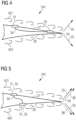
- Figure 4 shows another embodiment of the invention wherein the control unit 33 is omitted.
- the sensor 31 which is arranged at the suction side 27 is directly connected via connection means 34 with the actuator 32.
- connection means may be designed as flexible tubes or channels.
- the effect, namely the generated anti-pressure which is arranged and prepared to at least partly cancelling out the fluctuating surface pressures on the airfoil surface 27 is in principle comparable to the embodiment as illustrated in Figure 3 .
- the input for the actuator 32 only comes from one sensor at the suction side in the embodiment of Figure 4 compared to the embodiment of Figure 3 which implies that the arrangement is more simple, i.e. more robust and more inexpensive, but that it may eliminate slightly less of the noise 35 being generated at the trailing edge 24.
- FIG. 5 illustrates an embodiment of the invention where two membranes, both acting as sensor 31 and actuator 32, are provided. Since trailing edge noise typically radiates to the suction side 27 and the pressure side 28 in anti-phase, such an alternative passive noise cancellation technique may be advantageous.
- the suction side 27 of the airfoil and the pressure side 28 of the airfoil By connecting the suction side 27 of the airfoil and the pressure side 28 of the airfoil, the unsteady surface pressures on the suction side 27 and the pressure side 28 are equalized, however not necessarily to zero.
- the equalized pressure side and suction side fluctuating surface pressures arrive at the trailing edge 24, they both radiate the same sound signal to the pressure side and the suction side, respectively. However, these sound signals are radiated in anti-phase, so that the noise is at least partly cancelled out.
- the membrane position needs to account for the difference and convection speed, on the two sides, the suction side 27 and the pressure side 28 of the airfoil.
Landscapes
- Engineering & Computer Science (AREA)
- Life Sciences & Earth Sciences (AREA)
- Sustainable Development (AREA)
- Sustainable Energy (AREA)
- Chemical & Material Sciences (AREA)
- Combustion & Propulsion (AREA)
- Mechanical Engineering (AREA)
- General Engineering & Computer Science (AREA)
- Wind Motors (AREA)
Description
- The present invention relates to a rotor blade which is designed and configured for being exposed to a fluid, wherein flow-induced edge noise of the rotor blade is minimized. The invention is furthermore related to a wind turbine with at least one such rotor blade.
- When a rotor blade with a leading edge and a trailing edge is exposed to a fluid, such as air, flowing substantially from the leading edge to the trailing edge of the rotor blade, noise is generally generated at the edges of the rotor blade. The intensity of the noise and the frequency of the noise depends on many parameters, such as the properties of the fluid and the properties of the edge, namely the size of the edge and the shape of the edge, e.g. whether it is rounded or sharp.
- The noise being generated at the edges is typically undesired. In the example of a wind turbine which is installed onshore, i.e. at the ground, noise which is generated by the rotating rotor blades can be perceived as a nuisance by people in the vicinity of the wind turbine. For this reason, there exist various legal provisions and restrictions regarding the noise level which is allowed to be produced by such a wind turbine at a certain distance from the wind turbine. As a consequence, wind turbines may either need to be placed further away from residential areas or they have to be operated in such a manner that the maximum allowed level of noise is not exceeded. This means that wind turbines may need to be curtailed in certain conditions because of the flow-induced edge noise.
- As this issue is known since several years, various approaches for reducing flow-induced edge noise of a rotor blade have been proposed. These approaches include the shape and the design of the airfoil. In this context, particularly the shape and the design of the trailing edge of the rotor blade is of utmost importance. Aerodynamic add-ons may be added to or included in the rotor blade in order to minimize the flow-induced edge noise of the rotor blade. Well-known add-ons for noise reduction are serrations such as a serrated panel which is mounted to the pressure side or suction side of the rotor blade close to the trailing edge. However, the still existing and the still generated flow-induced edge noise could still be considerable.
-
WO2008043874 discloses to a system for suppressing and eliminating noise in wind turbines, formed by microphones disposed over the entire span of the blades and the towers.US2014142888 discloses a wind turbine system. Where a noise controller implements a noise mitigation measure in response to the detected rotational position of the rotor blade.US2012025530 discloses a controlling method for amplitude modulation of noise generated by wind turbines of wind farm. -
US2009097976A1 discloses another system for suppressing and eliminating noise in wind turbines. - Thus, there exists the desire to provide a concept how to further reduce flow-induced edge noise of a rotor blade.
- This objective is solved by the present invention which is described in the independent claim. Advantageous embodiments and modifications are expressed in the dependent claims. According to the invention, there is provided a rotor blade with a leading edge and a trailing edge, wherein the rotor blade is designed and configured for being exposed to a fluid flowing substantially from the leading edge to the trailing edge of the rotor blade. The rotor blade comprises a portion which has the shape of an airfoil comprising a pressure side and a suction side, each confined by the trailing edge and the leading edge. The rotor blade further comprises
- two membranes arranged at the surface of the rotor blade, one on the pressure side and one on the suction side of the airfoil, and connected by a flexible tube
- each membrane acting as a sensor for detecting flow characteristics of the fluid and as an actuator for producing an anti-noise signal
- the membranes arranged and prepared such that flow-induced edge noise of the rotor blade, which is generated by the fluid at the trailing edge of the rotor blade, is at least partly cancelled out by the anti-noise signal being produced by the membranes.
- In other words, the present invention describes a method how to reduce or even completely eliminate flow-induced edge noise from a rotor blade. This reduction or even elimination of the noise is achieved by the use of anti-noise. Since often times flow-induced edge noise is a broadband noise source, caused by a turbulent flow, the edge noise is random, i.e. stochastic. The acoustic pressure fluctuations are nondeterministic, meaning that they cannot be predicted in a temporal sense on the basis of the current or earlier acoustic signals, even when the statistical properties are known.
- However, the unsteady surface pressure pattern, that generates the sound at the edge, can be considered to convect unchanged with the flow along the chord of the rotor blade. Note that in practice this unchanged convection happens until a certain degree. This means that minimum changes of the unsteady surface pressure pattern is possible. This phenomenon is referred to in the literature as the 'frozen turbulence' assumption. In the present invention, this fact is used to detect the unsteady surface pressures upstream of the edge so that a noise cancelling anti-noise signal can be constructed and emitted in anti-phase at the moment when the turbulent eddies, which are responsible for the unsteady surface pressure pattern and noise generation, pass the edge. Therefore, essential components of the inventive arrangement at the rotor blade are at least one sensor for detecting the flow characteristics of the fluid and at least one actuator for producing the anti-noise signal. Both the sensor and the actuator are arranged at the surface of the rotor blade. This means that they are somehow integrated or added to the rotor blade at its surface. In order to prevent disadvantageous aerodynamic effects one option is to submerge and insert the sensor and the actuator into the shell or surface part of the rotor blade such that they are in contact with the surrounding air but they do not stick out and produce additional turbulences on the surface of the rotor blade.
- The actuator comprises a membrane. The sensor also comprises a membrane.
- In an embodiment of the invention, the rotor blade comprises a portion which has the shape of an airfoil comprising a pressure side and a suction side, and the pressure side and the suction side are each confined by the trailing edge and the leading edge of the rotor blade.
- In other words, in a preferred embodiment of the invention, the rotor blade is a lift producing rotor blade which has at least partly the shape of an airfoil. An airfoil is characterized in that it comprises a pressure side and a suction side and is able to produce lift when it is exposed to a fluid flowing substantially from the leading edge to the trailing edge of the rotor blade. As it is well-known to the person skilled in the art, the outer surface of such an airfoil shaped rotor blade is characterized by one portion which is referred to as the pressure side and which is confined at one side by the trailing edge and on the other side by the leading edge and the remaining part of the surface is typically referred to as the suction side of the rotor blade.
- The present invention particularly relates to a rotor blade of a wind turbine. However, the inventive concept is not limited to flow-induced edge noise of rotor blades of a wind turbine. It can also be applied to reduce flow-induced edge noise from, for example, aircraft wings, helicopter blades, fans, etc.
- In a non claimed example, the actuator comprises a loudspeaker. Such a loudspeaker is a well-known and readily available, inexpensive device which can be integrated or added to a rotor blade at almost any size in a simple and inexpensive manner, without affecting the aerodynamic flow around the blade.
- In a non claimed example, the sensor may exemplarily comprise a surface pressure transducer. Such a pressure transducer is also well-known and well-proven and may also be added or implemented and included to a rotor blade without large expenses or changes to the existing rotor blade.
- Note that the flow-induced edge noise, which is at least partly cancelled out by the anti-noise signal being produced by the actuator, preferably relates to trailing edge noise of the rotor blade, i.e. to noise which is flow-induced edge noise and which is generated in the trailing edge of the rotor blade. However, in principle, the present invention may be applied to other flow-induced edge noise sources as well, such as, for instance, leading edge in-flow turbulence noise or tip noise of the rotor blade.
- In another embodiment of the invention, the sensor is located upstream of the actuator with regard to the flow direction of the fluid.
- As it has been described, the rotor blade is designed and configured for being exposed to the fluid flowing substantially from the leading edge to the trailing edge of the rotor blade; therefore a flow direction can be assigned and defined to the exposed and surrounded rotor blade. In order to efficiently monitor and determine the characteristics of the unsteady surface pressure pattern, these are first in a temporal sense detected by the sensor which is located upstream of the actuator and the resulting and produced anti-noise signal can slightly afterwards be emitted or induced by the actuator. In the case of a rotor blade of a wind turbine to which a chord is assigned, this preferred embodiment may also be described that the actuator is closer to the trailing edge regarding a chordwise distance than the sensor.
- In a non claimed example, the sensor and the actuator are both located either on the pressure side or on the suction side of the rotor blade.
- This includes the possibility that there are arranged two sensors, one on the pressure side and one on the suction side and there are arranged one or two actuators, one on the pressure side and one on the suction side.
- In a non claimed example, the sensor is located at the suction side and the actuator is located at the pressure side, or the sensor is located at the pressure side and the actuator is located at the section side.
- Note that the sensor and the actuator may be directly connected with each other via connections means, such as a tube or a channel.
- This has the advantage of a very simple and robust arrangement. In this case, the distance, in particular the chord wise distance between the actuator and the sensor has to be carefully chosen based on expected unsteady surface pressure pattern and the velocity at which these surface pressure pattern travels towards the edge where the flow-induced edge noise is generated. If this is known or can be foreseen reasonably precisely, then this embodiment is a promising and advantageous way of implementing the inventive concept in a rotor blade.
- Alternatively, the rotor blade may further comprise a control unit for constructing the anti-noise signal and the actuator is connected with the sensor via connection means and the control unit.
- This has the advantage that a more optimized and tailored anti-noise signal may be produced and that the elimination of the flow induced noise may possibly be achieved in a larger extent. Such a control unit is advantageously located inside the rotor blade, which has the advantage that it does not disturb the air flow which is flowing across the rotor blade and that it is protected from the ambient and the influences of the ambient. Note that the actuator may be arranged and prepared to either induce surface pressure cancellation or to emit a sound signal.
- It is also conceivable that the air flow is somehow manipulated, for example by passive or active aerodynamic devices, in order to obtain a certain (fixed) thickness of the trailing edge boundary layer, so that a tuned (passive or active) anti-noise system can be applied. Having a fixed boundary layer thickness makes it easier to design an effective, tuned anti-noise system. Likewise, it is also conceivable that the air flow is somehow manipulated such that a particular (fixed) frequency content of the pressure fluctuations is obtained, so that a tuned (passive or active) anti-noise system can be applied. In other words, the thickness of the boundary layer and/or the frequency of the surface pressure fluctuations could be tuned in order to match a given anti-noise concept. This general principle, of manipulating the air flow to obtain a certain thickness of the boundary layer or a specific frequency content of the pressure fluctuations, can also be applied to other noise reduction concept, such as e.g. trailing edge serrations.
- The invention is also related to a wind turbine with at least one rotor blade as described in various embodiments above.
- Embodiments of the invention are now described, by way of example only, by the accompanying drawings, of which:
- Fig. 1
- shows a rotor blade;
- Fig. 2
- shows a profile of the rotor blade at a certain spanwise position;
- Fig. 3
- shows an embodiment of the invention comprising two sensors, a control unit and one actuator;
- Fig. 4
- shows another embodiment of the invention comprising a sensor and an actuator, which are directly connected via connection means; and
- Fig. 5
- shows a sensor which is mounted at the suction side and which is directly connected to an actuator which is mounted at the pressure side at the rotor blade.
- The illustration and the drawings is in schematic form. It is noted that in different figures, similar or identical elements may be provided with the same reference sign.
-
Figure 1 shows arotor blade 20. Therotor blade 20 comprises aroot 21 and atip 22. Therotor blade 20 furthermore comprises aleading edge 23 and a trailingedge 24.Figure 1 illustrates a top view or planar view onto therotor blade 20, namely onto the pressure side of the rotor blade. Therotor blade 20 is characterized by aspan 25, which is a straight line projecting away from theroot 21. In the case of a rotor blade of a wind turbine, wherein the rotor blade is pitchable about a pitch axis, the pitch axis coincides with thespan 25 as defined in the context of this patent application. - Furthermore, a plurality of
chords 26 may be assigned to therotor blade 20. Eachchord 26 is oriented perpendicular to thespan 25. Therefore, for each spanwise position starting at theroot 21 and reaching to thetip 22, achord 26 may be defined. Thechord 26 which is maximum, in other words which has a maximum length or extension, is referred to as themaximum chord 261. The area where themaximum chord 261 is located is referred to as theshoulder 262 of therotor blade 20. -
Figure 2 shows a schematic view of an airfoil of therotor blade 20. This airfoil or profile is taken perpendicular to thespan 25 of therotor blade 20. In other words this profile is a cross-sectional view at a specific radial position or spanwise position of the rotor blade. The leadingedge 23 can be seen and described as a relatively round edge, whereby the trailingedge 24 is relatively sharply designed. The straight line connecting the leadingedge 23 with the trailingedge 24 is referred to as thechord 26. - Note that the whole area from the leading
edge 23 up to ten per cent of the chord length of thechord 26 as measured from the leadingedge 23 is referred to as theleading edge section 231. Likewise, the area which is within ten per cent chord wise length away from the trailingedge 24 is referred to as the trailingedge section 241. - Note that in this schematic view the maximum thickness of the airfoil which is defined as the distance between the
pressure side 28 of thesuction side 27 is relatively large. This thickness often times considerably decreases towards thetip 22 of the rotor blade, at least in modern rotor blades of wind turbines. -
Figures 3 to 5 show three exemplary embodiments of the invention. -
Figure 3 shows a trailingedge section 241 comprising twosensors 31, onesensor 31 being positioned at thesuction side 27 of the rotor blade, and onesensor 31 being positioned at thepressure side 28 of the rotor blade. Thesesensors 31 are located upstream with regard to theactuator 32 which is arranged and positioned at thesuction side 27 of therotor blade 20. - Note that the invention is not limited to the case that the sensors are arranged in the trailing edge section of the rotor blade, i.e. in the area which is within ten per cent chord wise length away from the trailing edge of the rotor blade towards the leading edge of the rotor blade. Moreover, in an alternative embodiment of the invention, the sensor may also be located further upstream, e.g. twenty per cent, or thirty per cent, or even forty per cent chord wise length away from the trailing edge of the rotor blade towards the leading edge.
- Both
sensors 31 are connected with theactuator 32 by means of connection means 34. Between the twosensors 31 and theactuator 32 is arranged and located acontrol unit 33. The control unit is configured to produce the anti-noise signal based on the input which is received by thesensors 31. The anti-noise signal which is emitted by theactuator 32 is symbolized by thearrows 36. - The anti-noise 36 is deliberately chosen such that it destructively interferes with the
noise 35 which is generated and emitted at the trailingedge 24 of therotor blade 20. Note that in the illustration ofFigure 3 , two main directions of the noise are visualized by the twoarrows 35, one projecting away from the trailingedge 24 into the direction of the suction side, and one projecting away from the trailingedge 24 into the direction of the pressure side. In the exemplary embodiment ofFigure 3 , the anti-noise 36 mainly cancels out or minimizes thenoise 35 which is emitted and generated at the trailingedge 24 into the direction of thesuction side 27. If desired a pressure-side actuator could be added to also eliminate the noise emitted to the pressure side. Also note the turbulent boundary layer which is symbolized by suction side eddies 421 and pressure side eddies 422. The overall flow direction of the fluid is symbolized byreference sign 41. - It should be noted that, instead of anti-noise, the actuator (for example a membrane) may also produce anti-pressure, thus canceling the fluctuating surface pressures which are the source of the trailing edge noise. By (partly) eliminating the fluctuating surface pressures, noise radiation at the trailing edge is suppressed or completely prevented.
- In comparison with the embodiment as illustrated in
Figure 3 ,Figure 4 shows another embodiment of the invention wherein thecontrol unit 33 is omitted. In contrast, thesensor 31 which is arranged at thesuction side 27 is directly connected via connection means 34 with theactuator 32. These connection means may be designed as flexible tubes or channels. The effect, namely the generated anti-pressure which is arranged and prepared to at least partly cancelling out the fluctuating surface pressures on theairfoil surface 27 is in principle comparable to the embodiment as illustrated inFigure 3 . However, the input for theactuator 32 only comes from one sensor at the suction side in the embodiment ofFigure 4 compared to the embodiment ofFigure 3 which implies that the arrangement is more simple, i.e. more robust and more inexpensive, but that it may eliminate slightly less of thenoise 35 being generated at the trailingedge 24. - Finally,
Figure 5 illustrates an embodiment of the invention where two membranes, both acting assensor 31 andactuator 32, are provided. Since trailing edge noise typically radiates to thesuction side 27 and thepressure side 28 in anti-phase, such an alternative passive noise cancellation technique may be advantageous. By connecting thesuction side 27 of the airfoil and thepressure side 28 of the airfoil, the unsteady surface pressures on thesuction side 27 and thepressure side 28 are equalized, however not necessarily to zero. When the equalized pressure side and suction side fluctuating surface pressures arrive at the trailingedge 24, they both radiate the same sound signal to the pressure side and the suction side, respectively. However, these sound signals are radiated in anti-phase, so that the noise is at least partly cancelled out. In order to ensure that the equalized unsteady surface pressures reach the trailing edge at the same time, the membrane position needs to account for the difference and convection speed, on the two sides, thesuction side 27 and thepressure side 28 of the airfoil.
Claims (5)
- Rotor blade (20) with a leading edge (23) and a trailing edge (24), designed and configured for being exposed to a fluid flowing substantially from the leading edge (23) to the trailing edge (24) of the rotor blade (20), which rotor blade (20) comprises a portion which has the shape of an airfoil comprising a pressure side (28) and a suction side (27), each confined by the trailing edge and the leading edge (23), characterized in that the rotor blade (20) comprises- two membranes (31, 32) arranged at the surface of the rotor blade (20), one on the pressure side and one on the suction side of the airfoil, and connected by a flexible tube (34),- each membrane (31, 32) acting as a sensor (31) for detecting flow characteristics of the fluid and as an actuator (32) for producing an anti-noise signal (36),- the membranes (31, 32) arranged and prepared such that flow-induced edge noise (35) of the rotor blade (20), which is generated by the fluid at the trailing edge (24) of the rotor blade (20), is at least partly cancelled out by the anti-noise signal (36) being produced by the membranes (31, 32).
- Rotor blade (20) according to one of the preceding claim, wherein the membrane (31, 32) at the suction side is located upstream of the membrane (31, 32) at the pressure side with regard to the flow direction (41) of the fluid.
- Rotor blade (20) according to one of the preceding claims, wherein a membrane (31, 32) is arranged and prepared to induce at least partial cancellation of unsteady surface pressures.
- A rotor blade according to one of the preceding claims, wherein the positions of the membranes (31, 32) are chosen to account for a difference in convection speed of the fluid on the suction side (27) and the pressure side (28) of the airfoil.
- Wind turbine with at least one rotor blade (20) according to one of the preceding claims.
Priority Applications (5)
| Application Number | Priority Date | Filing Date | Title |
|---|---|---|---|
| PT161716956T PT3249216T (en) | 2016-05-27 | 2016-05-27 | Rotor blade with noise reduction means |
| ES16171695T ES2992787T3 (en) | 2016-05-27 | 2016-05-27 | Rotor blade with noise reduction means |
| EP16171695.6A EP3249216B1 (en) | 2016-05-27 | 2016-05-27 | Rotor blade with noise reduction means |
| US15/587,220 US10502187B2 (en) | 2016-05-27 | 2017-05-04 | Rotor blade with noise reduction means |
| CN201710385267.0A CN107448354B (en) | 2016-05-27 | 2017-05-26 | Rotor blade with noise reduction mechanism |
Applications Claiming Priority (1)
| Application Number | Priority Date | Filing Date | Title |
|---|---|---|---|
| EP16171695.6A EP3249216B1 (en) | 2016-05-27 | 2016-05-27 | Rotor blade with noise reduction means |
Publications (2)
| Publication Number | Publication Date |
|---|---|
| EP3249216A1 EP3249216A1 (en) | 2017-11-29 |
| EP3249216B1 true EP3249216B1 (en) | 2024-09-18 |
Family
ID=56081396
Family Applications (1)
| Application Number | Title | Priority Date | Filing Date |
|---|---|---|---|
| EP16171695.6A Active EP3249216B1 (en) | 2016-05-27 | 2016-05-27 | Rotor blade with noise reduction means |
Country Status (5)
| Country | Link |
|---|---|
| US (1) | US10502187B2 (en) |
| EP (1) | EP3249216B1 (en) |
| CN (1) | CN107448354B (en) |
| ES (1) | ES2992787T3 (en) |
| PT (1) | PT3249216T (en) |
Families Citing this family (7)
| Publication number | Priority date | Publication date | Assignee | Title |
|---|---|---|---|---|
| US11408394B2 (en) * | 2018-09-17 | 2022-08-09 | Siemens Gamesa Renewable Energy A/S | Sensor device for an aerodynamic element |
| EP3667081A1 (en) * | 2018-12-13 | 2020-06-17 | Siemens Gamesa Renewable Energy A/S | Wind turbine blade flow regulation |
| DK3812575T3 (en) | 2019-10-23 | 2023-08-21 | Siemens Gamesa Renewable Energy As | ROTOR BLADE WITH NOISE REDUCTION AGENTS |
| DK3812576T3 (en) | 2019-10-23 | 2023-07-17 | Siemens Gamesa Renewable Energy As | ROTOR BLADE WITH NOISE REDUCTION AGENTS |
| US11384732B2 (en) | 2020-07-13 | 2022-07-12 | Siemens Gamesa Renewable Energy A/S | Noise reduction means for a wind turbine blade, wind turbine blade, wind turbine, and method for noise reduction for a wind turbine blade |
| US11462204B2 (en) | 2020-09-08 | 2022-10-04 | Siemens Gamesa Renewable Energy A/S | Wind turbine and method for noise reduction for a wind turbine |
| US12553413B2 (en) | 2023-01-30 | 2026-02-17 | Siemens Gamesa Renewable Energy A/S | Wind turbine blade and wind turbine |
Citations (1)
| Publication number | Priority date | Publication date | Assignee | Title |
|---|---|---|---|---|
| US20090097976A1 (en) * | 2007-10-15 | 2009-04-16 | General Electric Company | Active damping of wind turbine blades |
Family Cites Families (19)
| Publication number | Priority date | Publication date | Assignee | Title |
|---|---|---|---|---|
| DE4494827D2 (en) | 1993-07-07 | 1996-08-22 | Leistritz Abgastech | Active silencer |
| JP2939940B2 (en) * | 1996-07-09 | 1999-08-25 | 日本電気株式会社 | Fan sound silencer |
| EP1338793A3 (en) | 2002-02-22 | 2010-09-01 | Mitsubishi Heavy Industries, Ltd. | Serrated wind turbine blade trailing edge |
| US7688984B2 (en) | 2003-11-26 | 2010-03-30 | The Regents Of The University Of California | Active noise control method and apparatus including feedforward and feedback controllers |
| ES2327696B2 (en) * | 2006-10-11 | 2011-07-28 | GAMESA INNOVATION & TECHNOLOGY, S.L. | SYSTEM OF SUPPRESSION AND CANCELLATION OF NOISE IN AEROGENERATORS. |
| EP2309119A1 (en) | 2008-08-06 | 2011-04-13 | Mitsubishi Heavy Industries, Ltd. | Windmill blade and wind power generator using same |
| US7896613B2 (en) | 2009-06-03 | 2011-03-01 | General Electric Company | System and method for wind turbine noise control and damage detection |
| US8041540B2 (en) * | 2009-12-09 | 2011-10-18 | General Electric Company | System, device, and method for acoustic and visual monitoring of a wind turbine |
| US8267657B2 (en) | 2010-12-16 | 2012-09-18 | General Electric Company | Noise reducer for rotor blade in wind turbine |
| US20110268558A1 (en) | 2010-12-20 | 2011-11-03 | General Electric Company | Noise reducer for rotor blade in wind turbine |
| US8232663B2 (en) * | 2011-06-30 | 2012-07-31 | General Electric Company | Controlling noise generated by wind turbines in a wind farm by de-synchronization of wind turbine rotors |
| US8430638B2 (en) | 2011-12-19 | 2013-04-30 | General Electric Company | Noise reducer for rotor blade in wind turbine |
| EP2885531B1 (en) * | 2012-08-17 | 2017-03-29 | LM WP Patent Holding A/S | A blade deflection monitoring system |
| CN203163197U (en) | 2012-10-25 | 2013-08-28 | 宁波奥克斯空调有限公司 | Mute air conditioner |
| US20140142888A1 (en) * | 2012-11-19 | 2014-05-22 | Elwha Llc | Mitigating wind turbine blade noise generation |
| WO2014124643A1 (en) * | 2013-02-14 | 2014-08-21 | Vestas Wind Systems A/S | Detecting blade structure abnormalities |
| US10280896B2 (en) * | 2013-05-24 | 2019-05-07 | Lm Wp Patent Holding A/S | Lightning protection system for a wind turbine blade |
| US20150132130A1 (en) * | 2013-11-12 | 2015-05-14 | NAB & Associates, Inc. | Wind turbine noise and fatigue control |
| US10385826B2 (en) * | 2014-09-12 | 2019-08-20 | Ge Infrastructure Technology, Llc | Wind turbine air deflector system control |
-
2016
- 2016-05-27 EP EP16171695.6A patent/EP3249216B1/en active Active
- 2016-05-27 PT PT161716956T patent/PT3249216T/en unknown
- 2016-05-27 ES ES16171695T patent/ES2992787T3/en active Active
-
2017
- 2017-05-04 US US15/587,220 patent/US10502187B2/en active Active
- 2017-05-26 CN CN201710385267.0A patent/CN107448354B/en active Active
Patent Citations (1)
| Publication number | Priority date | Publication date | Assignee | Title |
|---|---|---|---|---|
| US20090097976A1 (en) * | 2007-10-15 | 2009-04-16 | General Electric Company | Active damping of wind turbine blades |
Also Published As
| Publication number | Publication date |
|---|---|
| CN107448354A (en) | 2017-12-08 |
| PT3249216T (en) | 2024-11-25 |
| US20170342960A1 (en) | 2017-11-30 |
| ES2992787T3 (en) | 2024-12-18 |
| CN107448354B (en) | 2020-06-26 |
| EP3249216A1 (en) | 2017-11-29 |
| US10502187B2 (en) | 2019-12-10 |
Similar Documents
| Publication | Publication Date | Title |
|---|---|---|
| US10502187B2 (en) | Rotor blade with noise reduction means | |
| CN103620216B (en) | Improved Wind Turbine Noise Control Method | |
| US20150132130A1 (en) | Wind turbine noise and fatigue control | |
| EP2818702B1 (en) | Active systems and methods for producing ultrasonic sound emissions from wind turbines | |
| CN111771052B (en) | Controlling Wind Turbine Noise | |
| ES2901411T3 (en) | Operation of a wind turbine | |
| KR102079791B1 (en) | Method for evaluating the inflow on the rotor blades of the wind turbine, method for controlling the wind turbine, and wind turbine | |
| EP4150209B1 (en) | Wind turbine blade comprising noise reduction means, wind turbine, and method for noise reduction for a wind turbine blade | |
| US11927175B2 (en) | Rotor blade with noise reduction | |
| US12123398B2 (en) | Rotor blade with noise reduction means | |
| EP2851556A1 (en) | Arrangement to reduce noise of a wind turbine rotor blade | |
| US11428207B2 (en) | Wind turbine blade flow regulation | |
| CN112639284B (en) | Rotor blade for a wind power installation and wind power installation | |
| US12553413B2 (en) | Wind turbine blade and wind turbine | |
| US11536248B2 (en) | Wind power installation |
Legal Events
| Date | Code | Title | Description |
|---|---|---|---|
| PUAI | Public reference made under article 153(3) epc to a published international application that has entered the european phase |
Free format text: ORIGINAL CODE: 0009012 |
|
| STAA | Information on the status of an ep patent application or granted ep patent |
Free format text: STATUS: THE APPLICATION HAS BEEN PUBLISHED |
|
| AK | Designated contracting states |
Kind code of ref document: A1 Designated state(s): AL AT BE BG CH CY CZ DE DK EE ES FI FR GB GR HR HU IE IS IT LI LT LU LV MC MK MT NL NO PL PT RO RS SE SI SK SM TR |
|
| AX | Request for extension of the european patent |
Extension state: BA ME |
|
| STAA | Information on the status of an ep patent application or granted ep patent |
Free format text: STATUS: REQUEST FOR EXAMINATION WAS MADE |
|
| 17P | Request for examination filed |
Effective date: 20180528 |
|
| RBV | Designated contracting states (corrected) |
Designated state(s): AL AT BE BG CH CY CZ DE DK EE ES FI FR GB GR HR HU IE IS IT LI LT LU LV MC MK MT NL NO PL PT RO RS SE SI SK SM TR |
|
| STAA | Information on the status of an ep patent application or granted ep patent |
Free format text: STATUS: EXAMINATION IS IN PROGRESS |
|
| 17Q | First examination report despatched |
Effective date: 20181203 |
|
| RAP1 | Party data changed (applicant data changed or rights of an application transferred) |
Owner name: SIEMENS GAMESA RENEWABLE ENERGY A/S |
|
| GRAP | Despatch of communication of intention to grant a patent |
Free format text: ORIGINAL CODE: EPIDOSNIGR1 |
|
| STAA | Information on the status of an ep patent application or granted ep patent |
Free format text: STATUS: GRANT OF PATENT IS INTENDED |
|
| INTG | Intention to grant announced |
Effective date: 20240314 |
|
| RIN1 | Information on inventor provided before grant (corrected) |
Inventor name: RICHERT, BODO Inventor name: ENEVOLDSEN, PEDER BAY Inventor name: BIRKEMOSE, BO Inventor name: OERLEMANS, STEFAN |
|
| GRAS | Grant fee paid |
Free format text: ORIGINAL CODE: EPIDOSNIGR3 |
|
| GRAA | (expected) grant |
Free format text: ORIGINAL CODE: 0009210 |
|
| STAA | Information on the status of an ep patent application or granted ep patent |
Free format text: STATUS: THE PATENT HAS BEEN GRANTED |
|
| AK | Designated contracting states |
Kind code of ref document: B1 Designated state(s): AL AT BE BG CH CY CZ DE DK EE ES FI FR GB GR HR HU IE IS IT LI LT LU LV MC MK MT NL NO PL PT RO RS SE SI SK SM TR |
|
| REG | Reference to a national code |
Ref country code: GB Ref legal event code: FG4D |
|
| REG | Reference to a national code |
Ref country code: CH Ref legal event code: EP |
|
| REG | Reference to a national code |
Ref country code: IE Ref legal event code: FG4D |
|
| REG | Reference to a national code |
Ref country code: DE Ref legal event code: R096 Ref document number: 602016089428 Country of ref document: DE |
|
| REG | Reference to a national code |
Ref country code: PT Ref legal event code: SC4A Ref document number: 3249216 Country of ref document: PT Date of ref document: 20241125 Kind code of ref document: T Free format text: AVAILABILITY OF NATIONAL TRANSLATION Effective date: 20241118 |
|
| REG | Reference to a national code |
Ref country code: SE Ref legal event code: TRGR |
|
| REG | Reference to a national code |
Ref country code: ES Ref legal event code: FG2A Ref document number: 2992787 Country of ref document: ES Kind code of ref document: T3 Effective date: 20241218 |
|
| REG | Reference to a national code |
Ref country code: LT Ref legal event code: MG9D |
|
| PG25 | Lapsed in a contracting state [announced via postgrant information from national office to epo] |
Ref country code: NO Free format text: LAPSE BECAUSE OF FAILURE TO SUBMIT A TRANSLATION OF THE DESCRIPTION OR TO PAY THE FEE WITHIN THE PRESCRIBED TIME-LIMIT Effective date: 20241218 |
|
| PG25 | Lapsed in a contracting state [announced via postgrant information from national office to epo] |
Ref country code: GR Free format text: LAPSE BECAUSE OF FAILURE TO SUBMIT A TRANSLATION OF THE DESCRIPTION OR TO PAY THE FEE WITHIN THE PRESCRIBED TIME-LIMIT Effective date: 20241219 Ref country code: FI Free format text: LAPSE BECAUSE OF FAILURE TO SUBMIT A TRANSLATION OF THE DESCRIPTION OR TO PAY THE FEE WITHIN THE PRESCRIBED TIME-LIMIT Effective date: 20240918 |
|
| PG25 | Lapsed in a contracting state [announced via postgrant information from national office to epo] |
Ref country code: BG Free format text: LAPSE BECAUSE OF FAILURE TO SUBMIT A TRANSLATION OF THE DESCRIPTION OR TO PAY THE FEE WITHIN THE PRESCRIBED TIME-LIMIT Effective date: 20240918 |
|
| PG25 | Lapsed in a contracting state [announced via postgrant information from national office to epo] |
Ref country code: LV Free format text: LAPSE BECAUSE OF FAILURE TO SUBMIT A TRANSLATION OF THE DESCRIPTION OR TO PAY THE FEE WITHIN THE PRESCRIBED TIME-LIMIT Effective date: 20240918 |
|
| PG25 | Lapsed in a contracting state [announced via postgrant information from national office to epo] |
Ref country code: HR Free format text: LAPSE BECAUSE OF FAILURE TO SUBMIT A TRANSLATION OF THE DESCRIPTION OR TO PAY THE FEE WITHIN THE PRESCRIBED TIME-LIMIT Effective date: 20240918 |
|
| REG | Reference to a national code |
Ref country code: NL Ref legal event code: MP Effective date: 20240918 |
|
| PG25 | Lapsed in a contracting state [announced via postgrant information from national office to epo] |
Ref country code: RS Free format text: LAPSE BECAUSE OF FAILURE TO SUBMIT A TRANSLATION OF THE DESCRIPTION OR TO PAY THE FEE WITHIN THE PRESCRIBED TIME-LIMIT Effective date: 20241218 |
|
| PG25 | Lapsed in a contracting state [announced via postgrant information from national office to epo] |
Ref country code: RS Free format text: LAPSE BECAUSE OF FAILURE TO SUBMIT A TRANSLATION OF THE DESCRIPTION OR TO PAY THE FEE WITHIN THE PRESCRIBED TIME-LIMIT Effective date: 20241218 Ref country code: NO Free format text: LAPSE BECAUSE OF FAILURE TO SUBMIT A TRANSLATION OF THE DESCRIPTION OR TO PAY THE FEE WITHIN THE PRESCRIBED TIME-LIMIT Effective date: 20241218 Ref country code: LV Free format text: LAPSE BECAUSE OF FAILURE TO SUBMIT A TRANSLATION OF THE DESCRIPTION OR TO PAY THE FEE WITHIN THE PRESCRIBED TIME-LIMIT Effective date: 20240918 Ref country code: HR Free format text: LAPSE BECAUSE OF FAILURE TO SUBMIT A TRANSLATION OF THE DESCRIPTION OR TO PAY THE FEE WITHIN THE PRESCRIBED TIME-LIMIT Effective date: 20240918 Ref country code: GR Free format text: LAPSE BECAUSE OF FAILURE TO SUBMIT A TRANSLATION OF THE DESCRIPTION OR TO PAY THE FEE WITHIN THE PRESCRIBED TIME-LIMIT Effective date: 20241219 Ref country code: FI Free format text: LAPSE BECAUSE OF FAILURE TO SUBMIT A TRANSLATION OF THE DESCRIPTION OR TO PAY THE FEE WITHIN THE PRESCRIBED TIME-LIMIT Effective date: 20240918 Ref country code: BG Free format text: LAPSE BECAUSE OF FAILURE TO SUBMIT A TRANSLATION OF THE DESCRIPTION OR TO PAY THE FEE WITHIN THE PRESCRIBED TIME-LIMIT Effective date: 20240918 |
|
| REG | Reference to a national code |
Ref country code: AT Ref legal event code: MK05 Ref document number: 1724878 Country of ref document: AT Kind code of ref document: T Effective date: 20240918 |
|
| PG25 | Lapsed in a contracting state [announced via postgrant information from national office to epo] |
Ref country code: NL Free format text: LAPSE BECAUSE OF FAILURE TO SUBMIT A TRANSLATION OF THE DESCRIPTION OR TO PAY THE FEE WITHIN THE PRESCRIBED TIME-LIMIT Effective date: 20240918 |
|
| PG25 | Lapsed in a contracting state [announced via postgrant information from national office to epo] |
Ref country code: IS Free format text: LAPSE BECAUSE OF FAILURE TO SUBMIT A TRANSLATION OF THE DESCRIPTION OR TO PAY THE FEE WITHIN THE PRESCRIBED TIME-LIMIT Effective date: 20250118 |
|
| PG25 | Lapsed in a contracting state [announced via postgrant information from national office to epo] |
Ref country code: RO Free format text: LAPSE BECAUSE OF FAILURE TO SUBMIT A TRANSLATION OF THE DESCRIPTION OR TO PAY THE FEE WITHIN THE PRESCRIBED TIME-LIMIT Effective date: 20240918 Ref country code: SM Free format text: LAPSE BECAUSE OF FAILURE TO SUBMIT A TRANSLATION OF THE DESCRIPTION OR TO PAY THE FEE WITHIN THE PRESCRIBED TIME-LIMIT Effective date: 20240918 |
|
| PG25 | Lapsed in a contracting state [announced via postgrant information from national office to epo] |
Ref country code: EE Free format text: LAPSE BECAUSE OF FAILURE TO SUBMIT A TRANSLATION OF THE DESCRIPTION OR TO PAY THE FEE WITHIN THE PRESCRIBED TIME-LIMIT Effective date: 20240918 Ref country code: AT Free format text: LAPSE BECAUSE OF FAILURE TO SUBMIT A TRANSLATION OF THE DESCRIPTION OR TO PAY THE FEE WITHIN THE PRESCRIBED TIME-LIMIT Effective date: 20240918 |
|
| PG25 | Lapsed in a contracting state [announced via postgrant information from national office to epo] |
Ref country code: CZ Free format text: LAPSE BECAUSE OF FAILURE TO SUBMIT A TRANSLATION OF THE DESCRIPTION OR TO PAY THE FEE WITHIN THE PRESCRIBED TIME-LIMIT Effective date: 20240918 Ref country code: PL Free format text: LAPSE BECAUSE OF FAILURE TO SUBMIT A TRANSLATION OF THE DESCRIPTION OR TO PAY THE FEE WITHIN THE PRESCRIBED TIME-LIMIT Effective date: 20240918 |
|
| PG25 | Lapsed in a contracting state [announced via postgrant information from national office to epo] |
Ref country code: IT Free format text: LAPSE BECAUSE OF FAILURE TO SUBMIT A TRANSLATION OF THE DESCRIPTION OR TO PAY THE FEE WITHIN THE PRESCRIBED TIME-LIMIT Effective date: 20240918 Ref country code: SK Free format text: LAPSE BECAUSE OF FAILURE TO SUBMIT A TRANSLATION OF THE DESCRIPTION OR TO PAY THE FEE WITHIN THE PRESCRIBED TIME-LIMIT Effective date: 20240918 |
|
| REG | Reference to a national code |
Ref country code: DE Ref legal event code: R097 Ref document number: 602016089428 Country of ref document: DE |
|
| PGFP | Annual fee paid to national office [announced via postgrant information from national office to epo] |
Ref country code: DE Payment date: 20250528 Year of fee payment: 10 |
|
| PG25 | Lapsed in a contracting state [announced via postgrant information from national office to epo] |
Ref country code: DK Free format text: LAPSE BECAUSE OF FAILURE TO SUBMIT A TRANSLATION OF THE DESCRIPTION OR TO PAY THE FEE WITHIN THE PRESCRIBED TIME-LIMIT Effective date: 20240918 |
|
| PGFP | Annual fee paid to national office [announced via postgrant information from national office to epo] |
Ref country code: ES Payment date: 20250612 Year of fee payment: 10 |
|
| PGFP | Annual fee paid to national office [announced via postgrant information from national office to epo] |
Ref country code: PT Payment date: 20250506 Year of fee payment: 10 |
|
| PLBE | No opposition filed within time limit |
Free format text: ORIGINAL CODE: 0009261 |
|
| STAA | Information on the status of an ep patent application or granted ep patent |
Free format text: STATUS: NO OPPOSITION FILED WITHIN TIME LIMIT |
|
| PGFP | Annual fee paid to national office [announced via postgrant information from national office to epo] |
Ref country code: SE Payment date: 20250526 Year of fee payment: 10 |
|
| 26N | No opposition filed |
Effective date: 20250619 |
|
| REG | Reference to a national code |
Ref country code: CH Ref legal event code: H13 Free format text: ST27 STATUS EVENT CODE: U-0-0-H10-H13 (AS PROVIDED BY THE NATIONAL OFFICE) Effective date: 20251223 |
|
| PG25 | Lapsed in a contracting state [announced via postgrant information from national office to epo] |
Ref country code: LU Free format text: LAPSE BECAUSE OF NON-PAYMENT OF DUE FEES Effective date: 20250527 |
|
| PG25 | Lapsed in a contracting state [announced via postgrant information from national office to epo] |
Ref country code: CH Free format text: LAPSE BECAUSE OF NON-PAYMENT OF DUE FEES Effective date: 20250531 |
|
| REG | Reference to a national code |
Ref country code: BE Ref legal event code: MM Effective date: 20250531 |
|
| PG25 | Lapsed in a contracting state [announced via postgrant information from national office to epo] |
Ref country code: MC Free format text: LAPSE BECAUSE OF FAILURE TO SUBMIT A TRANSLATION OF THE DESCRIPTION OR TO PAY THE FEE WITHIN THE PRESCRIBED TIME-LIMIT Effective date: 20240918 |
|
| PGFP | Annual fee paid to national office [announced via postgrant information from national office to epo] |
Ref country code: GB Payment date: 20260323 Year of fee payment: 11 |
|
| PG25 | Lapsed in a contracting state [announced via postgrant information from national office to epo] |
Ref country code: IE Free format text: LAPSE BECAUSE OF NON-PAYMENT OF DUE FEES Effective date: 20250527 |
|
| PG25 | Lapsed in a contracting state [announced via postgrant information from national office to epo] |
Ref country code: BE Free format text: LAPSE BECAUSE OF NON-PAYMENT OF DUE FEES Effective date: 20250531 |
|
| PG25 | Lapsed in a contracting state [announced via postgrant information from national office to epo] |
Ref country code: FR Free format text: LAPSE BECAUSE OF NON-PAYMENT OF DUE FEES Effective date: 20250531 |