EP3249209A1 - Pressure regulator - Google Patents
Pressure regulator Download PDFInfo
- Publication number
- EP3249209A1 EP3249209A1 EP17172571.6A EP17172571A EP3249209A1 EP 3249209 A1 EP3249209 A1 EP 3249209A1 EP 17172571 A EP17172571 A EP 17172571A EP 3249209 A1 EP3249209 A1 EP 3249209A1
- Authority
- EP
- European Patent Office
- Prior art keywords
- piston
- pressure regulator
- groove
- face
- front wall
- Prior art date
- Legal status (The legal status is an assumption and is not a legal conclusion. Google has not performed a legal analysis and makes no representation as to the accuracy of the status listed.)
- Withdrawn
Links
- 239000000446 fuel Substances 0.000 claims abstract description 27
- 239000012530 fluid Substances 0.000 claims abstract description 14
- 230000000295 complement effect Effects 0.000 claims description 5
- 230000002093 peripheral effect Effects 0.000 claims description 5
- 238000005086 pumping Methods 0.000 claims description 3
- 238000002347 injection Methods 0.000 description 7
- 239000007924 injection Substances 0.000 description 7
- 239000002245 particle Substances 0.000 description 3
- 230000006835 compression Effects 0.000 description 2
- 238000007906 compression Methods 0.000 description 2
- 238000001816 cooling Methods 0.000 description 2
- 238000006073 displacement reaction Methods 0.000 description 2
- 238000011144 upstream manufacturing Methods 0.000 description 2
- 241000277301 Esociformes Species 0.000 description 1
- 230000001627 detrimental effect Effects 0.000 description 1
- 239000002283 diesel fuel Substances 0.000 description 1
- 239000000314 lubricant Substances 0.000 description 1
- 238000005461 lubrication Methods 0.000 description 1
- 230000001105 regulatory effect Effects 0.000 description 1
Images
Classifications
-
- F—MECHANICAL ENGINEERING; LIGHTING; HEATING; WEAPONS; BLASTING
- F02—COMBUSTION ENGINES; HOT-GAS OR COMBUSTION-PRODUCT ENGINE PLANTS
- F02M—SUPPLYING COMBUSTION ENGINES IN GENERAL WITH COMBUSTIBLE MIXTURES OR CONSTITUENTS THEREOF
- F02M59/00—Pumps specially adapted for fuel-injection and not provided for in groups F02M39/00 -F02M57/00, e.g. rotary cylinder-block type of pumps
- F02M59/44—Details, components parts, or accessories not provided for in, or of interest apart from, the apparatus of groups F02M59/02 - F02M59/42; Pumps having transducers, e.g. to measure displacement of pump rack or piston
- F02M59/46—Valves
-
- F—MECHANICAL ENGINEERING; LIGHTING; HEATING; WEAPONS; BLASTING
- F02—COMBUSTION ENGINES; HOT-GAS OR COMBUSTION-PRODUCT ENGINE PLANTS
- F02M—SUPPLYING COMBUSTION ENGINES IN GENERAL WITH COMBUSTIBLE MIXTURES OR CONSTITUENTS THEREOF
- F02M37/00—Apparatus or systems for feeding liquid fuel from storage containers to carburettors or fuel-injection apparatus; Arrangements for purifying liquid fuel specially adapted for, or arranged on, internal-combustion engines
- F02M37/0011—Constructional details; Manufacturing or assembly of elements of fuel systems; Materials therefor
- F02M37/0023—Valves in the fuel supply and return system
-
- F—MECHANICAL ENGINEERING; LIGHTING; HEATING; WEAPONS; BLASTING
- F02—COMBUSTION ENGINES; HOT-GAS OR COMBUSTION-PRODUCT ENGINE PLANTS
- F02M—SUPPLYING COMBUSTION ENGINES IN GENERAL WITH COMBUSTIBLE MIXTURES OR CONSTITUENTS THEREOF
- F02M37/00—Apparatus or systems for feeding liquid fuel from storage containers to carburettors or fuel-injection apparatus; Arrangements for purifying liquid fuel specially adapted for, or arranged on, internal-combustion engines
- F02M37/0011—Constructional details; Manufacturing or assembly of elements of fuel systems; Materials therefor
- F02M37/0023—Valves in the fuel supply and return system
- F02M37/0029—Pressure regulator in the low pressure fuel system
-
- F—MECHANICAL ENGINEERING; LIGHTING; HEATING; WEAPONS; BLASTING
- F02—COMBUSTION ENGINES; HOT-GAS OR COMBUSTION-PRODUCT ENGINE PLANTS
- F02M—SUPPLYING COMBUSTION ENGINES IN GENERAL WITH COMBUSTIBLE MIXTURES OR CONSTITUENTS THEREOF
- F02M63/00—Other fuel-injection apparatus having pertinent characteristics not provided for in groups F02M39/00 - F02M57/00 or F02M67/00; Details, component parts, or accessories of fuel-injection apparatus, not provided for in, or of interest apart from, the apparatus of groups F02M39/00 - F02M61/00 or F02M67/00; Combination of fuel pump with other devices, e.g. lubricating oil pump
- F02M63/0012—Valves
- F02M63/0031—Valves characterized by the type of valves, e.g. special valve member details, valve seat details, valve housing details
- F02M63/0033—Lift valves, i.e. having a valve member that moves perpendicularly to the plane of the valve seat
-
- F—MECHANICAL ENGINEERING; LIGHTING; HEATING; WEAPONS; BLASTING
- F02—COMBUSTION ENGINES; HOT-GAS OR COMBUSTION-PRODUCT ENGINE PLANTS
- F02M—SUPPLYING COMBUSTION ENGINES IN GENERAL WITH COMBUSTIBLE MIXTURES OR CONSTITUENTS THEREOF
- F02M63/00—Other fuel-injection apparatus having pertinent characteristics not provided for in groups F02M39/00 - F02M57/00 or F02M67/00; Details, component parts, or accessories of fuel-injection apparatus, not provided for in, or of interest apart from, the apparatus of groups F02M39/00 - F02M61/00 or F02M67/00; Combination of fuel pump with other devices, e.g. lubricating oil pump
- F02M63/0012—Valves
- F02M63/0031—Valves characterized by the type of valves, e.g. special valve member details, valve seat details, valve housing details
- F02M63/005—Pressure relief valves
-
- F—MECHANICAL ENGINEERING; LIGHTING; HEATING; WEAPONS; BLASTING
- F04—POSITIVE - DISPLACEMENT MACHINES FOR LIQUIDS; PUMPS FOR LIQUIDS OR ELASTIC FLUIDS
- F04B—POSITIVE-DISPLACEMENT MACHINES FOR LIQUIDS; PUMPS
- F04B53/00—Component parts, details or accessories not provided for in, or of interest apart from, groups F04B1/00 - F04B23/00 or F04B39/00 - F04B47/00
- F04B53/04—Draining
-
- F—MECHANICAL ENGINEERING; LIGHTING; HEATING; WEAPONS; BLASTING
- F04—POSITIVE - DISPLACEMENT MACHINES FOR LIQUIDS; PUMPS FOR LIQUIDS OR ELASTIC FLUIDS
- F04B—POSITIVE-DISPLACEMENT MACHINES FOR LIQUIDS; PUMPS
- F04B53/00—Component parts, details or accessories not provided for in, or of interest apart from, groups F04B1/00 - F04B23/00 or F04B39/00 - F04B47/00
- F04B53/10—Valves; Arrangement of valves
-
- F—MECHANICAL ENGINEERING; LIGHTING; HEATING; WEAPONS; BLASTING
- F02—COMBUSTION ENGINES; HOT-GAS OR COMBUSTION-PRODUCT ENGINE PLANTS
- F02M—SUPPLYING COMBUSTION ENGINES IN GENERAL WITH COMBUSTIBLE MIXTURES OR CONSTITUENTS THEREOF
- F02M2200/00—Details of fuel-injection apparatus, not otherwise provided for
- F02M2200/28—Details of throttles in fuel-injection apparatus
-
- F—MECHANICAL ENGINEERING; LIGHTING; HEATING; WEAPONS; BLASTING
- F02—COMBUSTION ENGINES; HOT-GAS OR COMBUSTION-PRODUCT ENGINE PLANTS
- F02M—SUPPLYING COMBUSTION ENGINES IN GENERAL WITH COMBUSTIBLE MIXTURES OR CONSTITUENTS THEREOF
- F02M2200/00—Details of fuel-injection apparatus, not otherwise provided for
- F02M2200/80—Fuel injection apparatus manufacture, repair or assembly
- F02M2200/8046—Fuel injection apparatus manufacture, repair or assembly the manufacture involving injection moulding, e.g. of plastic or metal
Definitions
- the present invention relates to a pressure regulator adapted to be arranged in the return circuit of a diesel high pressure pump.
- a high pressure fuel pump is typically arranged downstream a lift pump and upstream a high pressure injection unit.
- the high pressure fuel pump typically comprises a pressurizing unit wherein fuel is pressurized by a piston reciprocating in a bore and varying the volume of a compression chamber, said piston cooperating with a camshaft rotating between aligned bearings set in the body of a cambox.
- the body is further provided with a plurality of internal conduit defining a lubrication circuit and a return circuit enabling lubricant to flow around the camshaft, along the bearings and flow toward return outlet.
- a pressure regulator is arranged in said return circuit.
- the regulator comprises a body arranged in a bore of the pump body and, a piston slidably arranged in an internal bore provided inside said regulator body.
- the piston is urged toward a first position by a spring and, said piston only moves under the influence of a pressure spike.
- the pressure regulator adapted to be arranged in a fuel return circuit of a high pressure fuel pump, the pressure regulator comprising a body having a front seat member defining a front wall, a spring-stop member forming peripheral and rear walls.
- the body members defining an inner space surrounded by said walls and being in fluid communication with the return circuit via an inlet conduit arranged through the front wall and opening in the inner space in a seating face and, an outlet conduit arranged through the rear wall
- the pressure regulator further comprising a piston moveable inside said inner space and permanently urged toward a rest position by a spring compressed between a rear face of the piston and the rear wall, wherein, in said rest position a seat face of the piston is in complementary abutment against the seating face of the front wall, said seat face of the piston covering the opening of the inlet conduit, the piston being pushed away from said rest position when pressure in the inlet conduit reaches a predetermined threshold.
- the pressure regulator further comprises a viscosity controlled leak path, the fluid communication being limited to said viscosity controlled leak path when the piston is in rest position.
- the viscosity controlled leak path comprises a groove provided in the seat face of the piston.
- the viscosity controlled leak path comprises a groove provided in the seating face of the front wall of the regulator body.
- said groove radially extends from a first end opening in the inlet conduit to a second end opening in an annular space C surrounding the piston.
- the piston is cylindrical, said annular clearance being approximately of 200 ⁇ m to the diameter.
- the viscosity controlled leak path comprises a plurality of grooves.
- each groove forming the viscosity controlled leak path have a ratio L/D comprised between and, and preferably around where, L is the length of the groove and D is the depth of the groove.
- the depth D of the groove is comprised between 100 ⁇ m and 300 ⁇ m, preferably around 200 ⁇ m..
- the seating face of the front wall and the seat face of the piston are both parallel flat disc faces, the inlet conduit centrally opening in the seating face of the front wall.
- the body members, and the piston are plastic moulded parts.
- the invention further extends to a high pressure fuel pump having a body on which is fixed a pressurizing unit wherein a pumping cycle is performed by a piston cooperating with a camshaft, the body being provided with a return circuit in which is arranged a pressure regulator as described above.
- a pressure regulator 12 in a body 16 of a fuel pump 14.
- a fuel injection equipment also known as a common rail system.
- Such fuel injection equipment comprises a low pressure system wherein a lift pump sucks fuel in a tank and delivers it to the high pressure pump 14.
- said fuel is pressurized and delivered to a high pressure injection delivering system comprising a common rail and a plurality of fuel injectors.
- the high pressure pump 14 typically comprises a pressurizing unit wherein a piston reciprocally translates in a bore thus performing a pumping cycle in varying the volume of a compression chamber.
- the pressurizing unit is fixed on a cambox having a body 16 wherein a camshaft rotates between aligned bearings and imparts said reciprocating displacements to the piston.
- fuel leaks between the piston and the bore and gets in an inner volume defined in the cambox body 16.
- Said pump body 16 is further provided with conduits defining a return circuit 18 enabling fuel that, in use, fills said inner volume, to flow and return toward the low pressure system.
- the pressure regulator 12 is arranged in said return circuit 18 and is adapted to damp pressure spikes generated by the piston displacements, said pikes (or peaks) being able to damage the lift pump and, to alter the injection performance.
- the regulator 12 is arranged in a main bore 20 of said return circuit 18, the bore 20 extending along a main axis X and opening on the outer face 22 of the pump body, on the right of figure 1 .
- the upstream portion of the return circuit 18 forms an inlet channel 24, on the left of figure 1 and, the downstream portion of the return circuit 18 forms an outlet channel 26 axially extending through a back leak connector 28 adapted to complementary receive a return hose or pipe.
- the return circuit 18 comprises a bypass channel 30 opening in the bore 20, said bypass channel 30 enabling, in the specific arrangement of a high pressure pump, fuel flowing through the bearings of the camshaft to bypass the regulator 12 and to return directly toward the outlet.
- the regulator 12 comprises a two-part cylindrical body 32 press fitted in the bore 20, the back leak connector 28 being in turn press fitted behind the regulator.
- the body 32 defines an inner space S, in which is arranged a moveable piston 34 biased by a spring 36 toward a rest position RP.
- the regulator body 32 is the complementary arrangement in the bore 20 of a front seat member 38 and a spring stop member 48.
- the front seat member 38 defines a front wall 40 having an outer face 42 facing the inlet channel 24 and an inner face 44 forming a bottom face 44 of the inner space S.
- Said front wall 40 is further provided with an inlet conduit 46 extending throughout said front wall 40 from an outer opening in the outer face 42 to an inner opening in the center of said bottom face 44, the inlet conduit 46 creating a fluid communication F1 between said inlet channel 24 and the inner space S.
- the spring stop member 48 that complementary adjusts in the bore 20 against the seat member 38 has a cylindrical peripheral wall 50 which outer face is in flush continuity with the peripheral wall of the seat member 38, and a transverse rear wall 52 which, symmetrically to the seat member 38, is provided with an outlet conduit 54 extending throughout the rear wall 52 thus continuing said fluid communication F1 of the return circuit 18 between the inner space S and the outlet channel 26 toward the back leak connector 28.
- the spring-stop member 48 is further provided on its rear end, right on figure 1 , with an annular groove opening in a radial slot, thus creating said bypass fluid communication F2.
- the area of the bottom face 44 surrounding the opening of the inlet conduit forms a seating face 56 which, in the embodiment represented in flat and transverse but could have a tapered shape, or a spherical shape.
- the rear wall 52 is provided with a small cylindrical protrusion 58 through which extends the outlet conduit 54 and which serves as a location means for the lasts turns of the spring 36.
- the piston 34 is a thick disc shape member arranged in the inner space S and, as visible on the figure, the piston 36 is radially smaller than the inner space S defining around the piston 34 an annular clearance C.
- the piston 34 has a front seat face 60 adapted to cooperate with the seating face 56 of the front wall and, an opposite rear face 62 provided with another cylindrical protrusion 64 serving as a location means for the last turns of the other end of the spring 36, the spring 36 being compressed between the rear wall 52 and the piston 34 and, in absence of fluid pressure, as represented in figure 1 , the piston 34 is biased by the spring 36 in the rest position RP where its seat face 60 lies against the seating face 56 of the front wall.
- the seat face 60 of the piston is further provided with radial grooves 66, four being represented on the embodiment of figure 3 , only one on the embodiment of figure 4 .
- the grooves 66 have a length L and radially extend from the center of the seat face 60 of the piston to the outer edge of said seat face. Since the inlet conduit 46 opens in the center of the seating face 56, when in rest position RP, said grooves 66 create a small permanently open fluid path between the opening of the inlet conduit 46 and the annular clearance C.
- the groove 66 can be provided on the seat face 56 of the regulator body, or even on both the regulator body and the piston.
- Model with grooves 66 having a depth comprised between 100 ⁇ m and 300 ⁇ m and a ratio length of the groove over depth of 10 to 1 provided conclusive results. Further tests have been performed wherein the grooves 66 had a depth D of 200 ⁇ m and the annular clearance was of 250 ⁇ m to the diameter. A further important characteristic for viscosity control is the ratio length L over depth D of the groove 66. A ratio comprised between 8 and 12, preferably around 10 has demonstrated good results.
- the regulator body members and the piston can the plastic molded.
- the major advantage of said grooves 66 is that in operation, when the piston is in rest position RP, the grooves 66 maintain open the fluid communication F1 and create a viscosity controlled leak path enabling fuel in the return circuit 18 to permanently flow from the inlet channel 24 to the outlet channel 26 and cool the pump. As operational temperature varies, a higher leak flow is enabled at high temperature than at low temperature. This advantageously provided a cooling flow to the pump 14, the flow increasing with temperature.
- an advantage provided by the grooves 66 is that as said particles may get trapped in a groove 66 when in rest position RP, figure 5 , as soon as the piston 34 lifts of the seating face as represented in figure 6 , the fuel flow cleans the grooves 66 and re-establish the viscosity controlled leak path.
Landscapes
- Engineering & Computer Science (AREA)
- Mechanical Engineering (AREA)
- General Engineering & Computer Science (AREA)
- Chemical & Material Sciences (AREA)
- Combustion & Propulsion (AREA)
- Fuel-Injection Apparatus (AREA)
Abstract
Description
- The present invention relates to a pressure regulator adapted to be arranged in the return circuit of a diesel high pressure pump.
- In a fuel injection equipment, a high pressure fuel pump is typically arranged downstream a lift pump and upstream a high pressure injection unit. The high pressure fuel pump typically comprises a pressurizing unit wherein fuel is pressurized by a piston reciprocating in a bore and varying the volume of a compression chamber, said piston cooperating with a camshaft rotating between aligned bearings set in the body of a cambox. The body is further provided with a plurality of internal conduit defining a lubrication circuit and a return circuit enabling lubricant to flow around the camshaft, along the bearings and flow toward return outlet. Furthermore, to amortize pressure spikes that would be detrimental to the lift pump and to the injection unit performance, a pressure regulator is arranged in said return circuit.
- The regulator comprises a body arranged in a bore of the pump body and, a piston slidably arranged in an internal bore provided inside said regulator body. The piston is urged toward a first position by a spring and, said piston only moves under the influence of a pressure spike.
- In use the cambox heats up. The regulator often closes the return circuit and to ensure some cooling during said closed phases very small holes have been provided to bypass the closure of the regulator. Unfortunately said holes tend themselves to close because of particles flowing in fuel.
- Accordingly, it is an object of the present invention to resolve the above mentioned problems in providing a pressure regulator adapted to be arranged in a fuel return circuit of a high pressure fuel pump, the pressure regulator comprising a body having a front seat member defining a front wall, a spring-stop member forming peripheral and rear walls. The body members defining an inner space surrounded by said walls and being in fluid communication with the return circuit via an inlet conduit arranged through the front wall and opening in the inner space in a seating face and, an outlet conduit arranged through the rear wall, the pressure regulator further comprising a piston moveable inside said inner space and permanently urged toward a rest position by a spring compressed between a rear face of the piston and the rear wall, wherein, in said rest position a seat face of the piston is in complementary abutment against the seating face of the front wall, said seat face of the piston covering the opening of the inlet conduit, the piston being pushed away from said rest position when pressure in the inlet conduit reaches a predetermined threshold.
- The pressure regulator further comprises a viscosity controlled leak path, the fluid communication being limited to said viscosity controlled leak path when the piston is in rest position.
- Also, the viscosity controlled leak path comprises a groove provided in the seat face of the piston.
- Also, the viscosity controlled leak path comprises a groove provided in the seating face of the front wall of the regulator body.
- Also, said groove radially extends from a first end opening in the inlet conduit to a second end opening in an annular space C surrounding the piston.
- Also, the piston is cylindrical, said annular clearance being approximately of 200 µm to the diameter.
- Also, the viscosity controlled leak path comprises a plurality of grooves.
- Also, each groove forming the viscosity controlled leak path have a ratio L/D comprised between and, and preferably around where, L is the length of the groove and D is the depth of the groove.
- Also, the depth D of the groove is comprised between 100µm and 300µm, preferably around 200µm..
- Also, the seating face of the front wall and the seat face of the piston are both parallel flat disc faces, the inlet conduit centrally opening in the seating face of the front wall.
- Also, the body members, and the piston are plastic moulded parts.
- The invention further extends to a high pressure fuel pump having a body on which is fixed a pressurizing unit wherein a pumping cycle is performed by a piston cooperating with a camshaft, the body being provided with a return circuit in which is arranged a pressure regulator as described above.
- The present invention is now described by way of example with reference to the accompanying drawings in which:
-
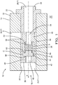
Figure 1 is a section of a pressure regulator as per the invention, arranged in a body of a high pressure fuel pump. -
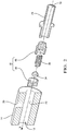
Figure 2 is an exploded view of the regulator offigure 1 . -
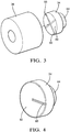
Figure 3 is a magnified view of a piston of the regulator. -
Figure 4 is an alternative embodiment of the piston. -
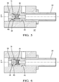
Figures 5 and 6 are sections similar tofigure 1 , representing the regulator in two operation mode. - In reference to the figures is described a new arrangement of a
pressure regulator 12 in abody 16 of afuel pump 14. Although the arrangement can be implemented within many products for regulating pressure of many different fluid, for purpose of clarity and illustration, the description is done in the context of a diesel fuelhigh pressure pump 14 arranged in a fuel injection equipment, also known as a common rail system. Such fuel injection equipment comprises a low pressure system wherein a lift pump sucks fuel in a tank and delivers it to thehigh pressure pump 14. In turn said fuel is pressurized and delivered to a high pressure injection delivering system comprising a common rail and a plurality of fuel injectors. - The
high pressure pump 14 typically comprises a pressurizing unit wherein a piston reciprocally translates in a bore thus performing a pumping cycle in varying the volume of a compression chamber. The pressurizing unit is fixed on a cambox having abody 16 wherein a camshaft rotates between aligned bearings and imparts said reciprocating displacements to the piston. In use, fuel leaks between the piston and the bore and gets in an inner volume defined in thecambox body 16. Saidpump body 16 is further provided with conduits defining areturn circuit 18 enabling fuel that, in use, fills said inner volume, to flow and return toward the low pressure system. - The
pressure regulator 12 is arranged in saidreturn circuit 18 and is adapted to damp pressure spikes generated by the piston displacements, said pikes (or peaks) being able to damage the lift pump and, to alter the injection performance. - The
regulator 12 is arranged in amain bore 20 of saidreturn circuit 18, thebore 20 extending along a main axis X and opening on theouter face 22 of the pump body, on the right offigure 1 . The upstream portion of thereturn circuit 18 forms aninlet channel 24, on the left offigure 1 and, the downstream portion of thereturn circuit 18 forms anoutlet channel 26 axially extending through aback leak connector 28 adapted to complementary receive a return hose or pipe. Also visible on the figure and vertically represented, thereturn circuit 18 comprises abypass channel 30 opening in thebore 20, saidbypass channel 30 enabling, in the specific arrangement of a high pressure pump, fuel flowing through the bearings of the camshaft to bypass theregulator 12 and to return directly toward the outlet. - More in details, the
regulator 12 comprises a two-partcylindrical body 32 press fitted in thebore 20, theback leak connector 28 being in turn press fitted behind the regulator. Thebody 32 defines an inner space S, in which is arranged amoveable piston 34 biased by aspring 36 toward a rest position RP. - The
regulator body 32 is the complementary arrangement in thebore 20 of afront seat member 38 and aspring stop member 48. Thefront seat member 38 defines afront wall 40 having anouter face 42 facing theinlet channel 24 and aninner face 44 forming abottom face 44 of the inner space S. Saidfront wall 40 is further provided with aninlet conduit 46 extending throughout saidfront wall 40 from an outer opening in theouter face 42 to an inner opening in the center of saidbottom face 44, theinlet conduit 46 creating a fluid communication F1 between saidinlet channel 24 and the inner space S. - The
spring stop member 48 that complementary adjusts in thebore 20 against theseat member 38 has a cylindricalperipheral wall 50 which outer face is in flush continuity with the peripheral wall of theseat member 38, and a transverserear wall 52 which, symmetrically to theseat member 38, is provided with anoutlet conduit 54 extending throughout therear wall 52 thus continuing said fluid communication F1 of thereturn circuit 18 between the inner space S and theoutlet channel 26 toward theback leak connector 28. - To accommodate a flow passage for the fuel flowing through the
bypass channel 30, the spring-stop member 48 is further provided on its rear end, right onfigure 1 , with an annular groove opening in a radial slot, thus creating said bypass fluid communication F2. - In the inner space S, the area of the
bottom face 44 surrounding the opening of the inlet conduit forms aseating face 56 which, in the embodiment represented in flat and transverse but could have a tapered shape, or a spherical shape. Opposite to saidseating face 56, therear wall 52 is provided with a smallcylindrical protrusion 58 through which extends theoutlet conduit 54 and which serves as a location means for the lasts turns of thespring 36. - The
piston 34 is a thick disc shape member arranged in the inner space S and, as visible on the figure, thepiston 36 is radially smaller than the inner space S defining around thepiston 34 an annular clearance C. Thepiston 34 has afront seat face 60 adapted to cooperate with theseating face 56 of the front wall and, an oppositerear face 62 provided with anothercylindrical protrusion 64 serving as a location means for the last turns of the other end of thespring 36, thespring 36 being compressed between therear wall 52 and thepiston 34 and, in absence of fluid pressure, as represented infigure 1 , thepiston 34 is biased by thespring 36 in the rest position RP where itsseat face 60 lies against theseating face 56 of the front wall. - In reference to
figures 3 and 4 , theseat face 60 of the piston is further provided withradial grooves 66, four being represented on the embodiment offigure 3 , only one on the embodiment offigure 4 . Thegrooves 66 have a length L and radially extend from the center of theseat face 60 of the piston to the outer edge of said seat face. Since theinlet conduit 46 opens in the center of theseating face 56, when in rest position RP, saidgrooves 66 create a small permanently open fluid path between the opening of theinlet conduit 46 and the annular clearance C. - In a non-represented alternative, the
groove 66 can be provided on theseat face 56 of the regulator body, or even on both the regulator body and the piston. - Model with
grooves 66 having a depth comprised between 100µm and 300µm and a ratio length of the groove over depth of 10 to 1 provided conclusive results. Further tests have been performed wherein thegrooves 66 had a depth D of 200µm and the annular clearance was of 250 µm to the diameter. A further important characteristic for viscosity control is the ratio length L over depth D of thegroove 66. A ratio comprised between 8 and 12, preferably around 10 has demonstrated good results. - A clearance C slightly smaller than 250µm, for instance about 200µm would be acceptable. Furthermore, the regulator body members and the piston can the plastic molded.
- The major advantage of said
grooves 66 is that in operation, when the piston is in rest position RP, thegrooves 66 maintain open the fluid communication F1 and create a viscosity controlled leak path enabling fuel in thereturn circuit 18 to permanently flow from theinlet channel 24 to theoutlet channel 26 and cool the pump. As operational temperature varies, a higher leak flow is enabled at high temperature than at low temperature. This advantageously provided a cooling flow to thepump 14, the flow increasing with temperature. - Furthermore, it is known than debris and particles may be present in the fuel and, an advantage provided by the
grooves 66 is that as said particles may get trapped in agroove 66 when in rest position RP,figure 5 , as soon as thepiston 34 lifts of the seating face as represented infigure 6 , the fuel flow cleans thegrooves 66 and re-establish the viscosity controlled leak path. -
- X
- main axis - regulator axis
- S
- inner space
- F1
- fluid communication
- F2
- bypass fluid communication
- C
- annular clearance
- RP
- rest position
- L
- length of the groove
- D
- depth of the groove
- 12
- pressure regulator
- 14
- high pressure pump
- 16
- pump body - cambox body
- 18
- return circuit
- 20
- main bore
- 22
- outer face of the cambox
- 24
- inlet channel
- 26
- outlet channel
- 28
- back leak connector
- 30
- bypass channel
- 32
- regulator hollow body
- 34
- piston
- 36
- spring
- 38
- seat member of the regulator body
- 40
- front wall
- 42
- outer face of the cambox
- 44
- inner face / bottom face
- 46
- inlet conduit
- 48
- spring-stop member
- 50
- peripheral wall
- 52
- rear wall
- 54
- outlet conduit
- 56
- seating face
- 58
- protrusion
- 60
- seat face of the piston
- 62
- rear face of the piston
- 64
- protrusion
- 66
- radial groove
Claims (11)
- Pressure regulator (12) adapted to be arranged in a fuel return circuit (18) of a high pressure fuel pump (14), the pressure regulator (12) comprising a body (32) having a front seat member (38) defining a front wall (40), a spring-stop member (48) forming peripheral (50) and rear (52) walls, said body members (38, 48) defining an inner space (S) surrounded by said walls and being in fluid communication (F1) with the return circuit (18) via an inlet conduit (46) arranged through the front wall (40) and opening in the inner space (S) in a seating face (56) and, an outlet conduit (54) arranged through the rear wall (52), the pressure regulator (12) further comprising a piston (34) moveable inside said inner space (S) and permanently urged toward a rest position (RP) by a spring (36) compressed between a rear face (62) of the piston and the rear wall (52), wherein, in said rest position (RP) a seat face (60) of the piston is in complementary abutment against the seating face (56) of the front wall, said seat face (60) of the piston covering the opening of the inlet conduit (46), the piston (34) being pushed away from said rest position (RP) when pressure in the inlet conduit (46) reaches a predetermined threshold,
characterized in that
the pressure regulator (12) further comprises a viscosity controlled leak path (66), the fluid communication (F1) being limited to said viscosity controlled leak path when the piston is in rest position (RP). - Pressure regulator (12) as claimed in any the preceding claim wherein the viscosity controlled leak path comprises a groove (66) provided in the seat face (60) of the piston.
- Pressure regulator as claimed in any one of the preceding claims wherein the viscosity controlled leak path comprises a groove (66) provided in the seating face of the front wall (40) of the regulator body.
- Pressure regulator (12) as claimed in any one of the claims 2 or 3 wherein said groove (66) radially extends from a first end opening in the inlet conduit (46) to a second end opening in an annular space (C) surrounding the piston (34).
- Pressure regulator (12) as claimed in claim 4 wherein the piston (34) is cylindrical, said annular clearance (C) being approximately of 200 µm to the diameter.
- Pressure regulator (12) as claimed in any one of the claims 4 or 5 wherein the viscosity controlled leak path comprises a plurality of grooves (66).
- Pressure regulator (12) as claimed in any one of the claims 2 to 6 wherein each groove (66) forming the viscosity controlled leak path have a ratio L/D comprised between 8 and 12, and preferably around 10 where, L is the length of the groove 66 and D is the depth of the groove 66.
- Pressure regulator (12) as claimed in claim 7 wherein the depth D of the groove 66 is comprised between 100µm and 300µm, preferably around 200µm.
- Pressure regulator (12) as claimed in the preceding claim wherein the seating face (56) of the front wall and the seat face (60) of the piston are both parallel flat disc faces, the inlet conduit (46) centrally opening in the seating face (56) of the front wall.
- Pressure regulator (12) as claimed in any one of the preceding claims wherein the body members (38, 42) and the piston (34) are plastic moulded parts.
- High pressure fuel pump (14) having a body (16) on which is fixed a pressurizing unit wherein a pumping cycle is performed by a piston cooperating with a camshaft, the body (16) being provided with a return circuit (18) in which is arranged a pressure regulator (12) as claimed in any one of the preceding claims.
Applications Claiming Priority (1)
| Application Number | Priority Date | Filing Date | Title |
|---|---|---|---|
| GBGB1609348.6A GB201609348D0 (en) | 2016-05-26 | 2016-05-26 | Pressure regulator |
Publications (1)
| Publication Number | Publication Date |
|---|---|
| EP3249209A1 true EP3249209A1 (en) | 2017-11-29 |
Family
ID=56410636
Family Applications (1)
| Application Number | Title | Priority Date | Filing Date |
|---|---|---|---|
| EP17172571.6A Withdrawn EP3249209A1 (en) | 2016-05-26 | 2017-05-23 | Pressure regulator |
Country Status (2)
| Country | Link |
|---|---|
| EP (1) | EP3249209A1 (en) |
| GB (1) | GB201609348D0 (en) |
Citations (6)
| Publication number | Priority date | Publication date | Assignee | Title |
|---|---|---|---|---|
| JP3501250B2 (en) * | 1995-11-13 | 2004-03-02 | 株式会社デンソー | Safety device for accumulator type fuel injection system |
| US20100242915A1 (en) * | 2007-11-23 | 2010-09-30 | Mariacarmela Masellis | Safety valve and high-pressure pump comprising said safety valve |
| EP2522854A1 (en) * | 2011-05-09 | 2012-11-14 | Robert Bosch Gmbh | Valve assembly for a high pressure fuel pump and high pressure fuel pump |
| US20130306166A1 (en) * | 2012-05-16 | 2013-11-21 | Ulrich Erb | Pressure-limiting valve |
| DE102013210760A1 (en) * | 2013-06-10 | 2014-12-11 | Robert Bosch Gmbh | High-pressure fuel pump for a fuel system for an internal combustion engine |
| WO2015066186A1 (en) * | 2013-11-01 | 2015-05-07 | Fca Us Llc | Biased normally open check valve assembly |
-
2016
- 2016-05-26 GB GBGB1609348.6A patent/GB201609348D0/en not_active Ceased
-
2017
- 2017-05-23 EP EP17172571.6A patent/EP3249209A1/en not_active Withdrawn
Patent Citations (6)
| Publication number | Priority date | Publication date | Assignee | Title |
|---|---|---|---|---|
| JP3501250B2 (en) * | 1995-11-13 | 2004-03-02 | 株式会社デンソー | Safety device for accumulator type fuel injection system |
| US20100242915A1 (en) * | 2007-11-23 | 2010-09-30 | Mariacarmela Masellis | Safety valve and high-pressure pump comprising said safety valve |
| EP2522854A1 (en) * | 2011-05-09 | 2012-11-14 | Robert Bosch Gmbh | Valve assembly for a high pressure fuel pump and high pressure fuel pump |
| US20130306166A1 (en) * | 2012-05-16 | 2013-11-21 | Ulrich Erb | Pressure-limiting valve |
| DE102013210760A1 (en) * | 2013-06-10 | 2014-12-11 | Robert Bosch Gmbh | High-pressure fuel pump for a fuel system for an internal combustion engine |
| WO2015066186A1 (en) * | 2013-11-01 | 2015-05-07 | Fca Us Llc | Biased normally open check valve assembly |
Also Published As
| Publication number | Publication date |
|---|---|
| GB201609348D0 (en) | 2016-07-13 |
Similar Documents
| Publication | Publication Date | Title |
|---|---|---|
| US1933454A (en) | Delivery valve of reciprocating pumps | |
| CN105264230B (en) | variable displacement lubricant pump | |
| CN105008719B (en) | Fuel pump for internal combustion engine | |
| CN103649537B (en) | Electromagnetic pump device | |
| KR20140010974A (en) | Pump unit for supplying fuel, preferably diesel oil, from a containing tank to an internal combustion engine | |
| CN105960531A (en) | Variable displacement lubricant pump | |
| JP2012122437A (en) | Fuel supply pump | |
| US10094346B1 (en) | Fuel pump with an improved maximum-pressure valve for a direct-injection system | |
| CN107636291A (en) | Fuel pump components | |
| GB2549746A (en) | High pressure fuel pump | |
| CN104033634B (en) | Overflow valve and low pressure oil transfer pump including the overflow valve | |
| EP3249209A1 (en) | Pressure regulator | |
| KR102456824B1 (en) | An oil lubricated common rail diesel pump | |
| US10415553B2 (en) | Device for choking a fluid flow and corresponding piston pump for delivering fluids | |
| KR102299585B1 (en) | Piston pump, particularly fuel pump for a fuel system for an internal combustion engine | |
| KR20170044754A (en) | High-pressure fuel pump, in particular for a fuel injection device of an internal combustion engine | |
| US20150192058A1 (en) | Selective internal distribution of engine motor oil | |
| EP3267029B1 (en) | Fuel pump with an improved maximum-pressure valve for a direct-injection system | |
| US11421637B2 (en) | High pressure diesel fuel pump pumping element | |
| CN203879664U (en) | Overflow valve and common rail system | |
| CN109653858A (en) | For adjusting the valve of the cooling fluid stream cooling for piston | |
| US11085581B2 (en) | Lubricating-grease pump and method for recovery of leakage grease of a lubricating-grease pump | |
| EP3023628A1 (en) | A fuel flow limiting valve for large internal combustion engines | |
| JP6885348B2 (en) | Oil jet device | |
| US10605214B2 (en) | Fuel pump having improved pumping behavior |
Legal Events
| Date | Code | Title | Description |
|---|---|---|---|
| PUAI | Public reference made under article 153(3) epc to a published international application that has entered the european phase |
Free format text: ORIGINAL CODE: 0009012 |
|
| AK | Designated contracting states |
Kind code of ref document: A1 Designated state(s): AL AT BE BG CH CY CZ DE DK EE ES FI FR GB GR HR HU IE IS IT LI LT LU LV MC MK MT NL NO PL PT RO RS SE SI SK SM TR |
|
| AX | Request for extension of the european patent |
Extension state: BA ME |
|
| 17P | Request for examination filed |
Effective date: 20180529 |
|
| RBV | Designated contracting states (corrected) |
Designated state(s): AL AT BE BG CH CY CZ DE DK EE ES FI FR GB GR HR HU IE IS IT LI LT LU LV MC MK MT NL NO PL PT RO RS SE SI SK SM TR |
|
| STAA | Information on the status of an ep patent application or granted ep patent |
Free format text: STATUS: THE APPLICATION IS DEEMED TO BE WITHDRAWN |
|
| 18D | Application deemed to be withdrawn |
Effective date: 20180530 |