EP3249180A1 - Retention hardware - Google Patents
Retention hardware Download PDFInfo
- Publication number
- EP3249180A1 EP3249180A1 EP17172560.9A EP17172560A EP3249180A1 EP 3249180 A1 EP3249180 A1 EP 3249180A1 EP 17172560 A EP17172560 A EP 17172560A EP 3249180 A1 EP3249180 A1 EP 3249180A1
- Authority
- EP
- European Patent Office
- Prior art keywords
- retention
- tab
- retention block
- block
- mating structure
- Prior art date
- Legal status (The legal status is an assumption and is not a legal conclusion. Google has not performed a legal analysis and makes no representation as to the accuracy of the status listed.)
- Granted
Links
Images


Classifications
-
- F—MECHANICAL ENGINEERING; LIGHTING; HEATING; WEAPONS; BLASTING
- F01—MACHINES OR ENGINES IN GENERAL; ENGINE PLANTS IN GENERAL; STEAM ENGINES
- F01D—NON-POSITIVE DISPLACEMENT MACHINES OR ENGINES, e.g. STEAM TURBINES
- F01D25/00—Component parts, details, or accessories, not provided for in, or of interest apart from, other groups
- F01D25/28—Supporting or mounting arrangements, e.g. for turbine casing
-
- F—MECHANICAL ENGINEERING; LIGHTING; HEATING; WEAPONS; BLASTING
- F01—MACHINES OR ENGINES IN GENERAL; ENGINE PLANTS IN GENERAL; STEAM ENGINES
- F01D—NON-POSITIVE DISPLACEMENT MACHINES OR ENGINES, e.g. STEAM TURBINES
- F01D25/00—Component parts, details, or accessories, not provided for in, or of interest apart from, other groups
- F01D25/24—Casings; Casing parts, e.g. diaphragms, casing fastenings
- F01D25/243—Flange connections; Bolting arrangements
-
- F—MECHANICAL ENGINEERING; LIGHTING; HEATING; WEAPONS; BLASTING
- F01—MACHINES OR ENGINES IN GENERAL; ENGINE PLANTS IN GENERAL; STEAM ENGINES
- F01D—NON-POSITIVE DISPLACEMENT MACHINES OR ENGINES, e.g. STEAM TURBINES
- F01D5/00—Blades; Blade-carrying members; Heating, heat-insulating, cooling or antivibration means on the blades or the members
- F01D5/02—Blade-carrying members, e.g. rotors
-
- F—MECHANICAL ENGINEERING; LIGHTING; HEATING; WEAPONS; BLASTING
- F02—COMBUSTION ENGINES; HOT-GAS OR COMBUSTION-PRODUCT ENGINE PLANTS
- F02C—GAS-TURBINE PLANTS; AIR INTAKES FOR JET-PROPULSION PLANTS; CONTROLLING FUEL SUPPLY IN AIR-BREATHING JET-PROPULSION PLANTS
- F02C3/00—Gas-turbine plants characterised by the use of combustion products as the working fluid
- F02C3/04—Gas-turbine plants characterised by the use of combustion products as the working fluid having a turbine driving a compressor
-
- F—MECHANICAL ENGINEERING; LIGHTING; HEATING; WEAPONS; BLASTING
- F02—COMBUSTION ENGINES; HOT-GAS OR COMBUSTION-PRODUCT ENGINE PLANTS
- F02C—GAS-TURBINE PLANTS; AIR INTAKES FOR JET-PROPULSION PLANTS; CONTROLLING FUEL SUPPLY IN AIR-BREATHING JET-PROPULSION PLANTS
- F02C3/00—Gas-turbine plants characterised by the use of combustion products as the working fluid
- F02C3/14—Gas-turbine plants characterised by the use of combustion products as the working fluid characterised by the arrangement of the combustion chamber in the plant
-
- F—MECHANICAL ENGINEERING; LIGHTING; HEATING; WEAPONS; BLASTING
- F23—COMBUSTION APPARATUS; COMBUSTION PROCESSES
- F23R—GENERATING COMBUSTION PRODUCTS OF HIGH PRESSURE OR HIGH VELOCITY, e.g. GAS-TURBINE COMBUSTION CHAMBERS
- F23R3/00—Continuous combustion chambers using liquid or gaseous fuel
- F23R3/42—Continuous combustion chambers using liquid or gaseous fuel characterised by the arrangement or form of the flame tubes or combustion chambers
- F23R3/60—Support structures; Attaching or mounting means
-
- F—MECHANICAL ENGINEERING; LIGHTING; HEATING; WEAPONS; BLASTING
- F01—MACHINES OR ENGINES IN GENERAL; ENGINE PLANTS IN GENERAL; STEAM ENGINES
- F01D—NON-POSITIVE DISPLACEMENT MACHINES OR ENGINES, e.g. STEAM TURBINES
- F01D9/00—Stators
- F01D9/02—Nozzles; Nozzle boxes; Stator blades; Guide conduits, e.g. individual nozzles
- F01D9/023—Transition ducts between combustor cans and first stage of the turbine in gas-turbine engines; their cooling or sealings
-
- F—MECHANICAL ENGINEERING; LIGHTING; HEATING; WEAPONS; BLASTING
- F05—INDEXING SCHEMES RELATING TO ENGINES OR PUMPS IN VARIOUS SUBCLASSES OF CLASSES F01-F04
- F05D—INDEXING SCHEME FOR ASPECTS RELATING TO NON-POSITIVE-DISPLACEMENT MACHINES OR ENGINES, GAS-TURBINES OR JET-PROPULSION PLANTS
- F05D2220/00—Application
- F05D2220/30—Application in turbines
- F05D2220/32—Application in turbines in gas turbines
-
- F—MECHANICAL ENGINEERING; LIGHTING; HEATING; WEAPONS; BLASTING
- F05—INDEXING SCHEMES RELATING TO ENGINES OR PUMPS IN VARIOUS SUBCLASSES OF CLASSES F01-F04
- F05D—INDEXING SCHEME FOR ASPECTS RELATING TO NON-POSITIVE-DISPLACEMENT MACHINES OR ENGINES, GAS-TURBINES OR JET-PROPULSION PLANTS
- F05D2260/00—Function
- F05D2260/30—Retaining components in desired mutual position
-
- F—MECHANICAL ENGINEERING; LIGHTING; HEATING; WEAPONS; BLASTING
- F05—INDEXING SCHEMES RELATING TO ENGINES OR PUMPS IN VARIOUS SUBCLASSES OF CLASSES F01-F04
- F05D—INDEXING SCHEME FOR ASPECTS RELATING TO NON-POSITIVE-DISPLACEMENT MACHINES OR ENGINES, GAS-TURBINES OR JET-PROPULSION PLANTS
- F05D2260/00—Function
- F05D2260/30—Retaining components in desired mutual position
- F05D2260/31—Retaining bolts or nuts
Definitions
- the disclosure relates generally to gas turbine engines and, more particularly, to fasteners and retention hardware suitable for use in gas turbine engines.
- Gas turbine engines have a generally cylindrical geometry housing various components and parts in a compact package.
- areas such as vane supports for example, the available room for hardware may be limited, particularly in a radial direction.
- Bolted joints in vane supports and other areas of the engine tend to limit the available design space and the ability to introduce additional hardware or design improvements, particularly with respect to legacy designs.
- a retention device comprises a retention block including an opening extending through the retention block in a first direction.
- a tab also extends in the first direction from the retention block.
- a fastener extends through the opening and includes a head configured to engage the retention block.
- a clinch nut is coupled to the fastener with an interface surface of the clinch nut configured to engage the tab of the retention block.
- a mating structure may have a flat surface configured to contact the tab of the retention block.
- the tab of the retention block may extend beyond the mating structure to contact the clinch nut.
- the interface surface of the clinch nut may contact an end portion of the tab.
- the retention block may include a retention tab oriented orthogonally to the tab of the retention block.
- the retention block may comprise a groove defined by a protrusion of the retention block.
- the protrusion may be orthogonal to the tab of the retention block.
- the retention block may be configured to transfer a load in the first direction of the tab into the mating structure.
- a high-pressure turbine oriented about an axis is also provided.
- the high-pressure turbine may include a first stage support structure with a mating structure extending radially and defining a cavity.
- a retention block may define an opening aligned with the cavity and have a first tab extending axially from the retention block. The first tab may contact the mating structure.
- a fastener may extend through the opening and the cavity.
- a clinch nut may be coupled to the fastener and engage the first tab of the retention block.
- a gas turbine engine may include a compressor configured to rotate about an axis.
- a combustor may be aft of the compressor and in fluid communication with the compressor.
- a turbine may be aft of the combustor and in fluid communication with the combustor.
- the turbine my also include a first stage support structure having a mating structure extending radially.
- a retention block may be aligned with the mating structure with a first tab extending axially from the retention block contacting a flat surface of the mating structure.
- a fastener may extend through the retention block and the mating structure.
- a clinch nut may be coupled to the fastener and may engage the first tab of the retention block.
- a retention tab may extend from the retention block in a radial direction.
- the retention tab may be configured to retain a portion of the combustor axially.
- a groove may be formed in the retention block opposite the retention tab and configured to retain a heat shield in an axial direction.
- the clinch nut may include an interface surface of configured to contact an end portion of the first tab for anti-rotation. The interface surface of the clinch nut may protrude circumferentially from the fastener.
- the retention block may include a second tab oriented parallel to the first tab and configured to engage the mating structure.
- the present disclosure relates to retention hardware having a low-profile.
- the retention hardware incorporates anti-rotation features into a low-profile design suitable for use in vane supports having limited clearance.
- the low-profile nature of the retention hardware tends to minimize the volume occupied by retention hardware, thereby leaving unoccupied volume to introduce additional hardware or design improvements.
- Gas turbine engine 20 may be a two-spool turbofan that generally incorporates a fan section 22, a compressor section 24, a combustor section 26 and a turbine section 28.
- Alternative engines may include, for example, an augmentor section among other systems or features.
- fan section 22 can drive coolant (e.g., air) along a bypass-flow path B while compressor section 24 can drive coolant along a core-flow path C for compression and communication into combustor section 26 then expansion through turbine section 28.
- coolant e.g., air
- compressor section 24 can drive coolant along a core-flow path C for compression and communication into combustor section 26 then expansion through turbine section 28.
- Gas turbine engine 20 may generally comprise a low speed spool 30 and a high speed spool 32 mounted for rotation about an engine central longitudinal axis A-A' relative to an engine static structure 36 via several bearing systems 38, 38-1, and 38-2. It should be understood that various bearing systems 38 at various locations may alternatively or additionally be provided, including for example, bearing system 38, bearing system 38-1, and bearing system 38-2.
- Low speed spool 30 may generally comprise an inner shaft 40 that interconnects a fan 42, a low-pressure compressor 44 and a low-pressure turbine 46.
- Inner shaft 40 may be connected to fan 42 through a geared architecture 48 that can drive fan 42 at a lower speed than low speed spool 30.
- Geared architecture 48 may comprise a gear assembly 60 enclosed within a gear housing 62.
- Gear assembly 60 couples inner shaft 40 to a rotating fan structure.
- High speed spool 32 may comprise an outer shaft 50 that interconnects a high-pressure compressor 52 and high-pressure turbine 54.
- Airfoils 55 coupled to a rotor of high-pressure turbine may rotate about the engine central longitudinal axis A-A' or airfoils 55 coupled to a stator may be rotationally fixed about engine central longitudinal axis A-A'.
- a combustor 56 may be located between high-pressure compressor 52 and high-pressure turbine 54.
- Mid-turbine frame 57 may support one or more bearing systems 38 in turbine section 28.
- Inner shaft 40 and outer shaft 50 may be concentric and rotate via bearing systems 38 about the engine central longitudinal axis A-A', which is collinear with their longitudinal axes.
- a "high-pressure" compressor or turbine experiences a higher pressure than a corresponding "low-pressure” compressor or turbine.
- the core airflow along core-flow path C may be compressed by low-pressure compressor 44 then high-pressure compressor 52, mixed and burned with fuel in combustor 56, then expanded over high-pressure turbine 54 and low-pressure turbine 46.
- Mid-turbine frame 57 includes airfoils 59, which are in the core airflow path. Turbines 46, 54 rotationally drive the respective low speed spool 30 and high speed spool 32 in response to the expansion.
- Gas turbine engine 20 may be, for example, a high-bypass ratio geared aircraft engine. In various embodiments, the bypass ratio of gas turbine engine 20 may be greater than about six. In various embodiments, the bypass ratio of gas turbine engine 20 may be greater than ten.
- geared architecture 48 may be an epicyclic gear train, such as a star gear system (sun gear in meshing engagement with a plurality of star gears supported by a carrier and in meshing engagement with a ring gear) or other gear system. Geared architecture 48 may have a gear reduction ratio of greater than about 2.3 and low-pressure turbine 46 may have a pressure ratio that is greater than about five. In various embodiments, the bypass ratio of gas turbine engine 20 is greater than about ten.
- the diameter of fan 42 may be significantly larger than that of the low-pressure compressor 44.
- Low-pressure turbine 46 pressure ratio may be measured prior to inlet of low-pressure turbine 46 as related to the pressure at the outlet of low-pressure turbine 46 prior to an exhaust nozzle. It should be understood, however, that the above parameters are exemplary of various embodiments of a suitable geared architecture engine and that the present disclosure contemplates other turbine engines including direct drive turbofans.
- the various components in gas turbine engine 20 may be coupled together by fasteners.
- the fasteners at various locations may include retention hardware.
- the fastener in the first stage of the high-pressure turbine the fastener may include combustor surge retention hardware.
- High pressure turbine 54 may include a first stage vane 200.
- a first stage blade outer air seal (BOAS) 202 may be disposed aft of first stage vane 200 and outboard (i.e., in direction D 1 ) from first stage blade 203.
- a second stage vane 204 may be disposed aft of first stage blade outer air seal 202.
- a second stage BOAS 206 may be disposed aft of second stage vane 204 with a second stage blade 207 disposed inboard (i.e., direction D 2 ) from second stage BOAS 206.
- high-pressure turbine 54 may be disposed aft of a combustor.
- Retention device 210 may be configured to retain an aft portion 212 of a combustor by interfacing with flange 214 extending outboard from aft portion 212 of the combustor. Retention device 210 may thus be configured to retain a combustor in response to a surge condition in which the pressure gradient in the combustor reverses.
- Retention device 210 may include a fastener 300 (e.g., a bolt) passing through a retention block 304, a mating structure 302 of the turbine case, and into a clinch nut 306.
- Mating structure 302 of the turbine case may have an interface surface 303 configured to contact the tab 308 of retention block 304.
- Contact tab may be a rectangular protrusion of retention block 304.
- Interface surface 303 may thus be a substantially flat surface configured to interface with a substantially flat surface of tab 308 of retention block 304.
- Tab 308 may extend in the axial direction (i.e., the x direction) when in high-pressure turbine 54 of FIG. 2 .
- retention block 304 may include a protrusion 310 that defines groove 312 in retention block 304.
- Groove 312 may interface with a structure such as heat shield 400 to provide axial retention (i.e., in the x direction) in response to a surge event.
- a surge event may be, for example, a reversal of pressure in the axial direction within the turbine and/or combustor.
- Protrusion 310 may be oriented in a plane (e.g., the y-z plane) orthogonal to the plane of tab 308 (e.g., the x-y plane).
- Tab 314 of retention block 304 may be shorter than tab 308 in the x direction.
- Tab 314 may also be defined in a plane parallel to the plane of tab 308 (e.g., with both tabs oriented in an x-y plane). In that regard, tab 314 and tab 308 may be configured to interface with mating structure 302 to anti-rotate retention block 304.
- retention block 304 may include a retention tab 316 configured to retain a combustor relative to retention block 304.
- retention tab 316 may project radially (i.e., in the y direction) from retention block 304 and interface with a flange and/or tab of a combustor to axially (i.e., in the x direction) retain the combustor.
- end portion 322 of tab 308 may extend beyond an axial terminus of mating structure 302 in the x direction. End portion 322 of tab 308 may interface with clinch nut 306 to anti-rotate clinch nut 306.
- Clinch nut 306 may include interface surface 318 and overhang 320. Interface surface 318 and/or overhang 320 may contact end portion 322 of tab 308. Interference surface of clinch nut may protrude circumferentially (i.e., in the z direction) from fastener 300 rather than radially (i.e., in the y direction).
- fastener 300 is disposed through opening 401 in retention block 304 and cavity 402 defined by mating structure 302 in the x direction.
- Clinch nut 306 includes tabs 404 that extend into cavity 402 of mating structure 302.
- Clinch nut 306 and head 406 of fastener 300 may be tightened against mating structure 302 and retention block 304, respectively.
- retention block 304 may resist forward movement of aft portion 212 of the combustor in the axial direction (i.e., x direction) by interfacing with flange 214.
- Retention block 304 may also resist movement of heat shield 400 in the same manner. Forward force transferred into retention block 304 may be transferred into first stage support structure 403 of high-pressure turbine 54 (of FIG. 2 ) and into the turbine case 208 (of FIG. 2 ).
- the retention device of the present disclosure orients the clinch nut with to extend circumferentially and interface with a tab extending from the retention block for anti-rotation of the nut during assembly.
- the circumferential orientation of the clinch nut tends to minimize radial space occupied by the retention device.
- the retention device tends to minimize the volume occupied by retention hardware in the radial direction.
- references to "one embodiment”, “an embodiment”, “an example embodiment”, etc. indicate that the embodiment described may include a particular feature, structure, or characteristic, but every embodiment may not necessarily include the particular feature, structure, or characteristic. Moreover, such phrases are not necessarily referring to the same embodiment. Further, when a particular feature, structure, or characteristic is described in connection with an embodiment, it is submitted that it is within the knowledge of one skilled in the art to affect such feature, structure, or characteristic in connection with other embodiments whether or not explicitly described. After reading the description, it will be apparent to one skilled in the relevant art(s) how to implement the disclosure in alternative embodiments.
- the terms “comprises”, “comprising”, or any other variation thereof, are intended to cover a non-exclusive inclusion, such that a process, method, article, or apparatus that comprises a list of elements does not include only those elements but may include other elements not expressly listed or inherent to such process, method, article, or apparatus.
Landscapes
- Engineering & Computer Science (AREA)
- Mechanical Engineering (AREA)
- General Engineering & Computer Science (AREA)
- Chemical & Material Sciences (AREA)
- Combustion & Propulsion (AREA)
- Turbine Rotor Nozzle Sealing (AREA)
Abstract
Description
- The disclosure relates generally to gas turbine engines and, more particularly, to fasteners and retention hardware suitable for use in gas turbine engines.
- Gas turbine engines have a generally cylindrical geometry housing various components and parts in a compact package. In areas such as vane supports, for example, the available room for hardware may be limited, particularly in a radial direction. Bolted joints in vane supports and other areas of the engine tend to limit the available design space and the ability to introduce additional hardware or design improvements, particularly with respect to legacy designs.
- A retention device is provided. The retention device comprises a retention block including an opening extending through the retention block in a first direction. A tab also extends in the first direction from the retention block. A fastener extends through the opening and includes a head configured to engage the retention block. A clinch nut is coupled to the fastener with an interface surface of the clinch nut configured to engage the tab of the retention block.
- In various embodiments, a mating structure may have a flat surface configured to contact the tab of the retention block. The tab of the retention block may extend beyond the mating structure to contact the clinch nut. The interface surface of the clinch nut may contact an end portion of the tab. The retention block may include a retention tab oriented orthogonally to the tab of the retention block. The retention block may comprise a groove defined by a protrusion of the retention block. The protrusion may be orthogonal to the tab of the retention block. The retention block may be configured to transfer a load in the first direction of the tab into the mating structure.
- A high-pressure turbine oriented about an axis is also provided. The high-pressure turbine may include a first stage support structure with a mating structure extending radially and defining a cavity. A retention block may define an opening aligned with the cavity and have a first tab extending axially from the retention block. The first tab may contact the mating structure. A fastener may extend through the opening and the cavity. A clinch nut may be coupled to the fastener and engage the first tab of the retention block.
- In various embodiments, a retention tab may extend from the retention block in a radial direction. The retention tab may be configured to transfer an axial load into the first stage support structure. A groove may be formed in the retention block and configured to transfer an axial load into the first stage support structure. The clinch nut may include an interface surface of that contacts an end portion of the first tab. The interface surface of the clinch nut may protrude circumferentially from the fastener. The retention block may comprise a second tab oriented parallel to the first tab. The second tab may be configured to engage the mating structure.
- A gas turbine engine is also disclosed. The gas turbine engine may include a compressor configured to rotate about an axis. A combustor may be aft of the compressor and in fluid communication with the compressor. A turbine may be aft of the combustor and in fluid communication with the combustor. The turbine my also include a first stage support structure having a mating structure extending radially. A retention block may be aligned with the mating structure with a first tab extending axially from the retention block contacting a flat surface of the mating structure. A fastener may extend through the retention block and the mating structure. A clinch nut may be coupled to the fastener and may engage the first tab of the retention block.
- In various embodiments, a retention tab may extend from the retention block in a radial direction. The retention tab may be configured to retain a portion of the combustor axially. A groove may be formed in the retention block opposite the retention tab and configured to retain a heat shield in an axial direction. The clinch nut may include an interface surface of configured to contact an end portion of the first tab for anti-rotation. The interface surface of the clinch nut may protrude circumferentially from the fastener. The retention block may include a second tab oriented parallel to the first tab and configured to engage the mating structure.
- The forgoing features and elements may be combined in various combinations without exclusivity, unless expressly indicated herein otherwise. These features and elements as well as the operation of the disclosed embodiments will become more apparent in light of the following description and accompanying drawings.
- The subject matter of the present disclosure is particularly pointed out and distinctly claimed in the concluding portion of the specification. A more complete understanding of the present disclosures, however, may best be obtained by referring to the detailed description and claims when considered in connection with the drawing figures, wherein like numerals denote like elements.
-
FIG. 1 illustrates an exemplary gas turbine engine, in accordance with various embodiments; -
FIG. 2 illustrates an exemplary engine structure incorporating low-profile hardware, in accordance with various embodiments; -
FIG. 3 illustrates a perspective view of low-profile retention hardware, in accordance with various embodiments; and -
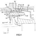
FIG. 4 illustrates a cross-sectional view of low-profile retention hardware, in accordance with various embodiments. - The detailed description of exemplary embodiments herein makes reference to the accompanying drawings, which show exemplary embodiments by way of illustration and their best mode. While these exemplary embodiments are described in sufficient detail to enable those skilled in the art to practice the disclosures, it should be understood that other embodiments may be realized and that logical, chemical, and mechanical changes may be made without departing from the scope of the disclosures. Thus, the detailed description herein is presented for purposes of illustration only and not of limitation. For example, the steps recited in any of the method or process descriptions may be executed in any order and are not necessarily limited to the order presented. Furthermore, any reference to singular includes plural embodiments, and any reference to more than one component or step may include a singular embodiment or step. Also, any reference to attached, fixed, connected or the like may include permanent, removable, temporary, partial, full and/or any other possible attachment option. Additionally, any reference to without contact (or similar phrases) may also include reduced contact or minimal contact.
- The present disclosure relates to retention hardware having a low-profile. The retention hardware incorporates anti-rotation features into a low-profile design suitable for use in vane supports having limited clearance. The low-profile nature of the retention hardware tends to minimize the volume occupied by retention hardware, thereby leaving unoccupied volume to introduce additional hardware or design improvements.
- Referring now to
FIG. 1 , an exemplarygas turbine engine 20 is shown, in accordance with various embodiments.Gas turbine engine 20 may be a two-spool turbofan that generally incorporates afan section 22, acompressor section 24, acombustor section 26 and aturbine section 28. Alternative engines may include, for example, an augmentor section among other systems or features. In operation,fan section 22 can drive coolant (e.g., air) along a bypass-flow path B whilecompressor section 24 can drive coolant along a core-flow path C for compression and communication intocombustor section 26 then expansion throughturbine section 28. Although depicted as a turbofangas turbine engine 20 herein, it should be understood that the concepts described herein are not limited to use with turbofans as the teachings may be applied to other types of turbine engines including three-spool architectures. -
Gas turbine engine 20 may generally comprise alow speed spool 30 and ahigh speed spool 32 mounted for rotation about an engine central longitudinal axis A-A' relative to an enginestatic structure 36 viaseveral bearing systems 38, 38-1, and 38-2. It should be understood that various bearingsystems 38 at various locations may alternatively or additionally be provided, including for example, bearingsystem 38, bearing system 38-1, and bearing system 38-2. -
Low speed spool 30 may generally comprise aninner shaft 40 that interconnects afan 42, a low-pressure compressor 44 and a low-pressure turbine 46.Inner shaft 40 may be connected to fan 42 through a gearedarchitecture 48 that can drivefan 42 at a lower speed thanlow speed spool 30.Geared architecture 48 may comprise agear assembly 60 enclosed within agear housing 62.Gear assembly 60 couplesinner shaft 40 to a rotating fan structure.High speed spool 32 may comprise anouter shaft 50 that interconnects a high-pressure compressor 52 and high-pressure turbine 54.Airfoils 55 coupled to a rotor of high-pressure turbine may rotate about the engine central longitudinal axis A-A' orairfoils 55 coupled to a stator may be rotationally fixed about engine central longitudinal axis A-A'. - A
combustor 56 may be located between high-pressure compressor 52 and high-pressure turbine 54.Mid-turbine frame 57 may support one ormore bearing systems 38 inturbine section 28.Inner shaft 40 andouter shaft 50 may be concentric and rotate via bearingsystems 38 about the engine central longitudinal axis A-A', which is collinear with their longitudinal axes. As used herein, a "high-pressure" compressor or turbine experiences a higher pressure than a corresponding "low-pressure" compressor or turbine. - The core airflow along core-flow path C may be compressed by low-
pressure compressor 44 then high-pressure compressor 52, mixed and burned with fuel incombustor 56, then expanded over high-pressure turbine 54 and low-pressure turbine 46.Mid-turbine frame 57 includesairfoils 59, which are in the core airflow path.Turbines low speed spool 30 andhigh speed spool 32 in response to the expansion. -
Gas turbine engine 20 may be, for example, a high-bypass ratio geared aircraft engine. In various embodiments, the bypass ratio ofgas turbine engine 20 may be greater than about six. In various embodiments, the bypass ratio ofgas turbine engine 20 may be greater than ten. In various embodiments, gearedarchitecture 48 may be an epicyclic gear train, such as a star gear system (sun gear in meshing engagement with a plurality of star gears supported by a carrier and in meshing engagement with a ring gear) or other gear system.Geared architecture 48 may have a gear reduction ratio of greater than about 2.3 and low-pressure turbine 46 may have a pressure ratio that is greater than about five. In various embodiments, the bypass ratio ofgas turbine engine 20 is greater than about ten. In various embodiments, the diameter offan 42 may be significantly larger than that of the low-pressure compressor 44. Low-pressure turbine 46 pressure ratio may be measured prior to inlet of low-pressure turbine 46 as related to the pressure at the outlet of low-pressure turbine 46 prior to an exhaust nozzle. It should be understood, however, that the above parameters are exemplary of various embodiments of a suitable geared architecture engine and that the present disclosure contemplates other turbine engines including direct drive turbofans. - The various components in
gas turbine engine 20 may be coupled together by fasteners. The fasteners at various locations may include retention hardware. For example, in the first stage of the high-pressure turbine the fastener may include combustor surge retention hardware. - With reference to
FIG. 2 , an exemplary high-pressure turbine 54 is shown, in accordance with various embodiments.High pressure turbine 54 may include afirst stage vane 200. A first stage blade outer air seal (BOAS) 202 may be disposed aft offirst stage vane 200 and outboard (i.e., in direction D1) fromfirst stage blade 203. Asecond stage vane 204 may be disposed aft of first stage bladeouter air seal 202. Asecond stage BOAS 206 may be disposed aft ofsecond stage vane 204 with asecond stage blade 207 disposed inboard (i.e., direction D2) fromsecond stage BOAS 206. - In various embodiments, high-
pressure turbine 54 may be disposed aft of a combustor.Retention device 210 may be configured to retain anaft portion 212 of a combustor by interfacing withflange 214 extending outboard fromaft portion 212 of the combustor.Retention device 210 may thus be configured to retain a combustor in response to a surge condition in which the pressure gradient in the combustor reverses. - Referring now to
FIGs. 3 and4 ,retention device 210 is shown, in accordance with various embodiments.Retention device 210 may include a fastener 300 (e.g., a bolt) passing through aretention block 304, amating structure 302 of the turbine case, and into aclinch nut 306.Mating structure 302 of the turbine case may have aninterface surface 303 configured to contact thetab 308 ofretention block 304. Contact tab may be a rectangular protrusion ofretention block 304.Interface surface 303 may thus be a substantially flat surface configured to interface with a substantially flat surface oftab 308 ofretention block 304.Tab 308 may extend in the axial direction (i.e., the x direction) when in high-pressure turbine 54 ofFIG. 2 . - In various embodiments,
retention block 304 may include aprotrusion 310 that definesgroove 312 inretention block 304. Groove 312 may interface with a structure such asheat shield 400 to provide axial retention (i.e., in the x direction) in response to a surge event. A surge event may be, for example, a reversal of pressure in the axial direction within the turbine and/or combustor.Protrusion 310 may be oriented in a plane (e.g., the y-z plane) orthogonal to the plane of tab 308 (e.g., the x-y plane).Tab 314 ofretention block 304 may be shorter thantab 308 in the x direction.Tab 314 may also be defined in a plane parallel to the plane of tab 308 (e.g., with both tabs oriented in an x-y plane). In that regard,tab 314 andtab 308 may be configured to interface withmating structure 302 toanti-rotate retention block 304. - In various embodiments,
retention block 304 may include aretention tab 316 configured to retain a combustor relative toretention block 304. As described in greater detail below,retention tab 316 may project radially (i.e., in the y direction) fromretention block 304 and interface with a flange and/or tab of a combustor to axially (i.e., in the x direction) retain the combustor. - In various embodiments,
end portion 322 oftab 308 may extend beyond an axial terminus ofmating structure 302 in the x direction.End portion 322 oftab 308 may interface withclinch nut 306 toanti-rotate clinch nut 306.Clinch nut 306 may includeinterface surface 318 andoverhang 320.Interface surface 318 and/oroverhang 320 may contactend portion 322 oftab 308. Interference surface of clinch nut may protrude circumferentially (i.e., in the z direction) fromfastener 300 rather than radially (i.e., in the y direction). - Referring now to
FIG. 4 ,fastener 300 is disposed throughopening 401 inretention block 304 andcavity 402 defined bymating structure 302 in the x direction.Clinch nut 306 includestabs 404 that extend intocavity 402 ofmating structure 302.Clinch nut 306 andhead 406 offastener 300 may be tightened againstmating structure 302 andretention block 304, respectively. In that regard,retention block 304 may resist forward movement ofaft portion 212 of the combustor in the axial direction (i.e., x direction) by interfacing withflange 214.Retention block 304 may also resist movement ofheat shield 400 in the same manner. Forward force transferred intoretention block 304 may be transferred into firststage support structure 403 of high-pressure turbine 54 (ofFIG. 2 ) and into the turbine case 208 (ofFIG. 2 ). - In various embodiments, the retention device of the present disclosure orients the clinch nut with to extend circumferentially and interface with a tab extending from the retention block for anti-rotation of the nut during assembly. The circumferential orientation of the clinch nut tends to minimize radial space occupied by the retention device. Thus, the retention device tends to minimize the volume occupied by retention hardware in the radial direction.
- Benefits, other advantages, and solutions to problems have been described herein with regard to specific embodiments. Furthermore, the connecting lines shown in the various figures contained herein are intended to represent exemplary functional relationships and/or physical couplings between the various elements. It should be noted that many alternative or additional functional relationships or physical connections may be present in a practical system. However, the benefits, advantages, solutions to problems, and any elements that may cause any benefit, advantage, or solution to occur or become more pronounced are not to be construed as critical, required, or essential features or elements of the disclosures. The scope of the disclosures is accordingly to be limited by nothing other than the appended claims, in which reference to an element in the singular is not intended to mean "one and only one" unless explicitly so stated, but rather "one or more." Moreover, where a phrase similar to "at least one of A, B, or C" is used in the claims, it is intended that the phrase be interpreted to mean that A alone may be present in an embodiment, B alone may be present in an embodiment, C alone may be present in an embodiment, or that any combination of the elements A, B and C may be present in a single embodiment; for example, A and B, A and C, B and C, or A and B and C. Different cross-hatching is used throughout the figures to denote different parts but not necessarily to denote the same or different materials.
- Systems, methods and apparatus are provided herein. In the detailed description herein, references to "one embodiment", "an embodiment", "an example embodiment", etc., indicate that the embodiment described may include a particular feature, structure, or characteristic, but every embodiment may not necessarily include the particular feature, structure, or characteristic. Moreover, such phrases are not necessarily referring to the same embodiment. Further, when a particular feature, structure, or characteristic is described in connection with an embodiment, it is submitted that it is within the knowledge of one skilled in the art to affect such feature, structure, or characteristic in connection with other embodiments whether or not explicitly described. After reading the description, it will be apparent to one skilled in the relevant art(s) how to implement the disclosure in alternative embodiments.
- As used herein, the terms "comprises", "comprising", or any other variation thereof, are intended to cover a non-exclusive inclusion, such that a process, method, article, or apparatus that comprises a list of elements does not include only those elements but may include other elements not expressly listed or inherent to such process, method, article, or apparatus.
Claims (15)
- A retention device (210) comprising:a retention block (304) including an opening (401) extending through the retention block (304) in a first direction, wherein the retention block (304) comprises a tab (308) extending in the first direction;a fastener (300) extending through the opening (401) and comprising a head (406) configured to engage the retention block (304); anda clinch nut (306) coupled to the fastener (300) and comprising an interface surface (318) configured to engage the tab (308) of the retention block (304).
- The retention device (210) of claim 1, further comprising a mating structure (302) having a flat surface (303) configured to contact the tab (308) of the retention block (304).
- The retention device (210) of claim 2, wherein the tab (308) of the retention block (304) extends beyond the mating structure (302) to contact the clinch nut (306).
- The retention device (210) of claim 2 or 3, wherein the retention block (304) is configured to transfer a load in the first direction of the tab (308) into the mating structure (302).
- The retention device (210) of any preceding claim, wherein the interface surface (318) of the clinch nut (306) contacts an end portion (322) of the tab (308).
- The retention device (210) of any preceding claim, wherein the retention block (304) comprises a retention tab (316) oriented orthogonally to the tab (308) of the retention block (304), wherein, optionally, the retention block (304) comprises a groove (312) defined by a protrusion (310) of the retention block (304), wherein the protrusion (310) is orthogonal to the tab (308) of the retention block (304).
- A high-pressure turbine (54) oriented about an axis (A-A'), comprising:a first stage support structure (403) having a mating structure (302) extending radially, wherein the mating structure (302) defines a cavity (402);a retention block (304) defining an opening (401) aligned with the cavity (402), wherein a first tab (308) extends axially from the retention block (304) and contacts a flat surface (303) of the mating structure (302);a fastener (300) extending through the opening (401) and the cavity (402); anda clinch nut (306) coupled to the fastener (300) and engaging the first tab (308) of the retention block (304).
- The high-pressure turbine (54) of claim 7, further comprising a retention tab (316) extending from the retention block (304) in a radial direction.
- The high-pressure turbine (54) of claim 8, wherein the retention tab (316) is configured to transfer an axial load into the first stage support structure (403).
- The high-pressure turbine (54) of claim 7, 8 or 9, further comprising a groove (312) formed in the retention block (304), wherein the groove (312) is configured to transfer an axial load into the first stage support structure (403).
- A gas turbine engine (20) comprising:a compressor (24) configured to rotate about an axis (A-A');a combustor (26) aft of the compressor (24) and in fluid communication with the compressor (24);a turbine (28) aft of the combustor (26) and in fluid communication with the combustor (26), wherein the turbine (28) comprises a first stage support structure (403) having a mating structure (302) extending radially;a retention block (304) aligned with the mating structure (302), wherein a first tab (308) extends axially from the retention block (304) and contacts a flat surface (303) of the mating structure (302);a fastener (300) extending through the retention block (304) and the mating structure (302); anda clinch nut (306) coupled to the fastener (300) and engaging the first tab (308) of the retention block (304).
- The gas turbine engine (20) of claim 11, further comprising a retention tab (316) extending from the retention block (304) in a radial direction, wherein the retention tab (316) is configured to retain a portion of the combustor (26) axially, optionally, further comprising a groove (312) formed in the retention block (304) opposite the retention tab (316), wherein the groove (312) is configured to retain a heat shield (400) in an axial direction.
- The high-pressure turbine (54) or gas turbine engine (20) of any of claims 8 to 12, wherein the clinch nut (306) comprises an interface surface (318) configured to contact an end portion (322) of the first tab (308), optionally for anti-rotation.
- The high-pressure turbine (54) or gas turbine engine (20) of claim 13, wherein the interface surface (318) of the clinch nut (306) protrudes circumferentially from the fastener (300).
- The high-pressure turbine (54) or gas turbine engine (20) of claim 13 or 14, wherein the retention block (304) comprises a second tab (314) oriented parallel to the first tab (308) and configured to engage the mating structure (302).
Applications Claiming Priority (1)
| Application Number | Priority Date | Filing Date | Title |
|---|---|---|---|
| US15/161,716 US10563542B2 (en) | 2016-05-23 | 2016-05-23 | Retention hardware |
Publications (2)
| Publication Number | Publication Date |
|---|---|
| EP3249180A1 true EP3249180A1 (en) | 2017-11-29 |
| EP3249180B1 EP3249180B1 (en) | 2020-07-01 |
Family
ID=58800663
Family Applications (1)
| Application Number | Title | Priority Date | Filing Date |
|---|---|---|---|
| EP17172560.9A Active EP3249180B1 (en) | 2016-05-23 | 2017-05-23 | Retention hardware |
Country Status (2)
| Country | Link |
|---|---|
| US (2) | US10563542B2 (en) |
| EP (1) | EP3249180B1 (en) |
Cited By (1)
| Publication number | Priority date | Publication date | Assignee | Title |
|---|---|---|---|---|
| EP4227497A1 (en) * | 2022-02-11 | 2023-08-16 | Pratt & Whitney Canada Corp. | Flange assembly for fastener retention and method for assembling same |
Families Citing this family (1)
| Publication number | Priority date | Publication date | Assignee | Title |
|---|---|---|---|---|
| US10598046B2 (en) * | 2018-07-11 | 2020-03-24 | United Technologies Corporation | Support straps and method of assembly for gas turbine engine |
Citations (3)
| Publication number | Priority date | Publication date | Assignee | Title |
|---|---|---|---|---|
| US5848874A (en) * | 1997-05-13 | 1998-12-15 | United Technologies Corporation | Gas turbine stator vane assembly |
| US20130202450A1 (en) * | 2012-02-03 | 2013-08-08 | Richard Ivakitch | Fastening system for fan and shaft interconnection |
| WO2013165868A1 (en) * | 2012-05-01 | 2013-11-07 | United Technologies Corporation | Gas turbine engine combustor surge retention |
Family Cites Families (7)
| Publication number | Priority date | Publication date | Assignee | Title |
|---|---|---|---|---|
| US3269702A (en) * | 1964-01-13 | 1966-08-30 | United Aircraft Corp | Nozzle vane assembly |
| US3443617A (en) * | 1967-11-02 | 1969-05-13 | Standard Pressed Steel Co | Press insert |
| US5006025A (en) * | 1989-12-13 | 1991-04-09 | Avibank Mfg., Inc. | Self-locking nut |
| US6116013A (en) * | 1998-01-02 | 2000-09-12 | Siemens Westinghouse Power Corporation | Bolted gas turbine combustor transition coupling |
| US8021091B2 (en) * | 2004-11-05 | 2011-09-20 | Pem Management, Inc. | Rotatable captivated nut |
| US20070212192A1 (en) * | 2006-03-10 | 2007-09-13 | United Technologies Corporation | Self-retaining bolt |
| US9140125B2 (en) * | 2012-02-02 | 2015-09-22 | Pratt & Whitney Canada Corp. | Segmented rings with captive nuts for fan bolts |
-
2016
- 2016-05-23 US US15/161,716 patent/US10563542B2/en active Active
-
2017
- 2017-05-23 EP EP17172560.9A patent/EP3249180B1/en active Active
-
2020
- 2020-01-06 US US16/734,965 patent/US11215083B2/en active Active
Patent Citations (3)
| Publication number | Priority date | Publication date | Assignee | Title |
|---|---|---|---|---|
| US5848874A (en) * | 1997-05-13 | 1998-12-15 | United Technologies Corporation | Gas turbine stator vane assembly |
| US20130202450A1 (en) * | 2012-02-03 | 2013-08-08 | Richard Ivakitch | Fastening system for fan and shaft interconnection |
| WO2013165868A1 (en) * | 2012-05-01 | 2013-11-07 | United Technologies Corporation | Gas turbine engine combustor surge retention |
Cited By (1)
| Publication number | Priority date | Publication date | Assignee | Title |
|---|---|---|---|---|
| EP4227497A1 (en) * | 2022-02-11 | 2023-08-16 | Pratt & Whitney Canada Corp. | Flange assembly for fastener retention and method for assembling same |
Also Published As
| Publication number | Publication date |
|---|---|
| US20200149432A1 (en) | 2020-05-14 |
| US20170335720A1 (en) | 2017-11-23 |
| US10563542B2 (en) | 2020-02-18 |
| EP3249180B1 (en) | 2020-07-01 |
| US11215083B2 (en) | 2022-01-04 |
Similar Documents
| Publication | Publication Date | Title |
|---|---|---|
| US10533446B2 (en) | Alternative W-seal groove arrangement | |
| US10018066B2 (en) | Mini blind stator leakage reduction | |
| WO2014197074A2 (en) | Curvic seal for gas turbine enigne | |
| EP3246517A1 (en) | Fastener openings for stress distribution | |
| US11215083B2 (en) | Retention hardware | |
| EP3722633A1 (en) | Vibration isolator assembly | |
| US10215232B2 (en) | Bearing with non-uniform cage clearance | |
| EP3748134B1 (en) | Vane airfoil shapes for embedded members | |
| EP3081748B1 (en) | Gas turbine engine system comprising a seal ring | |
| US11070041B2 (en) | Egress seal fitting | |
| US20180080477A1 (en) | Anti-rotation stator vane assembly | |
| EP3730828A1 (en) | Dynamic sleeve seal fittings | |
| EP3453835B1 (en) | Fan exit stator assembly | |
| EP3477046A1 (en) | Anti-rotation assembly for two coupled shafts, gas turbine engine and corresponding method of assembling a gas turbine engine | |
| US11371632B2 (en) | Compliant jumper tube fitting | |
| US11408300B2 (en) | Rotor overspeed protection assembly | |
| EP3470685A1 (en) | Gap closing wearliner | |
| US9897210B2 (en) | Knife edge seal tree | |
| US10519870B2 (en) | Multiple mounting surface gearbox |
Legal Events
| Date | Code | Title | Description |
|---|---|---|---|
| PUAI | Public reference made under article 153(3) epc to a published international application that has entered the european phase |
Free format text: ORIGINAL CODE: 0009012 |
|
| STAA | Information on the status of an ep patent application or granted ep patent |
Free format text: STATUS: THE APPLICATION HAS BEEN PUBLISHED |
|
| AK | Designated contracting states |
Kind code of ref document: A1 Designated state(s): AL AT BE BG CH CY CZ DE DK EE ES FI FR GB GR HR HU IE IS IT LI LT LU LV MC MK MT NL NO PL PT RO RS SE SI SK SM TR |
|
| AX | Request for extension of the european patent |
Extension state: BA ME |
|
| STAA | Information on the status of an ep patent application or granted ep patent |
Free format text: STATUS: REQUEST FOR EXAMINATION WAS MADE |
|
| 17P | Request for examination filed |
Effective date: 20180529 |
|
| RBV | Designated contracting states (corrected) |
Designated state(s): AL AT BE BG CH CY CZ DE DK EE ES FI FR GB GR HR HU IE IS IT LI LT LU LV MC MK MT NL NO PL PT RO RS SE SI SK SM TR |
|
| STAA | Information on the status of an ep patent application or granted ep patent |
Free format text: STATUS: EXAMINATION IS IN PROGRESS |
|
| 17Q | First examination report despatched |
Effective date: 20190627 |
|
| GRAP | Despatch of communication of intention to grant a patent |
Free format text: ORIGINAL CODE: EPIDOSNIGR1 |
|
| STAA | Information on the status of an ep patent application or granted ep patent |
Free format text: STATUS: GRANT OF PATENT IS INTENDED |
|
| INTG | Intention to grant announced |
Effective date: 20200306 |
|
| GRAS | Grant fee paid |
Free format text: ORIGINAL CODE: EPIDOSNIGR3 |
|
| GRAA | (expected) grant |
Free format text: ORIGINAL CODE: 0009210 |
|
| STAA | Information on the status of an ep patent application or granted ep patent |
Free format text: STATUS: THE PATENT HAS BEEN GRANTED |
|
| AK | Designated contracting states |
Kind code of ref document: B1 Designated state(s): AL AT BE BG CH CY CZ DE DK EE ES FI FR GB GR HR HU IE IS IT LI LT LU LV MC MK MT NL NO PL PT RO RS SE SI SK SM TR |
|
| REG | Reference to a national code |
Ref country code: CH Ref legal event code: EP Ref country code: AT Ref legal event code: REF Ref document number: 1286376 Country of ref document: AT Kind code of ref document: T Effective date: 20200715 |
|
| REG | Reference to a national code |
Ref country code: IE Ref legal event code: FG4D |
|
| REG | Reference to a national code |
Ref country code: DE Ref legal event code: R096 Ref document number: 602017018900 Country of ref document: DE |
|
| REG | Reference to a national code |
Ref country code: LT Ref legal event code: MG4D |
|
| PG25 | Lapsed in a contracting state [announced via postgrant information from national office to epo] |
Ref country code: BG Free format text: LAPSE BECAUSE OF FAILURE TO SUBMIT A TRANSLATION OF THE DESCRIPTION OR TO PAY THE FEE WITHIN THE PRESCRIBED TIME-LIMIT Effective date: 20201001 |
|
| REG | Reference to a national code |
Ref country code: NL Ref legal event code: MP Effective date: 20200701 |
|
| REG | Reference to a national code |
Ref country code: AT Ref legal event code: MK05 Ref document number: 1286376 Country of ref document: AT Kind code of ref document: T Effective date: 20200701 |
|
| PG25 | Lapsed in a contracting state [announced via postgrant information from national office to epo] |
Ref country code: CZ Free format text: LAPSE BECAUSE OF FAILURE TO SUBMIT A TRANSLATION OF THE DESCRIPTION OR TO PAY THE FEE WITHIN THE PRESCRIBED TIME-LIMIT Effective date: 20200701 Ref country code: HR Free format text: LAPSE BECAUSE OF FAILURE TO SUBMIT A TRANSLATION OF THE DESCRIPTION OR TO PAY THE FEE WITHIN THE PRESCRIBED TIME-LIMIT Effective date: 20200701 Ref country code: ES Free format text: LAPSE BECAUSE OF FAILURE TO SUBMIT A TRANSLATION OF THE DESCRIPTION OR TO PAY THE FEE WITHIN THE PRESCRIBED TIME-LIMIT Effective date: 20200701 Ref country code: LT Free format text: LAPSE BECAUSE OF FAILURE TO SUBMIT A TRANSLATION OF THE DESCRIPTION OR TO PAY THE FEE WITHIN THE PRESCRIBED TIME-LIMIT Effective date: 20200701 Ref country code: SE Free format text: LAPSE BECAUSE OF FAILURE TO SUBMIT A TRANSLATION OF THE DESCRIPTION OR TO PAY THE FEE WITHIN THE PRESCRIBED TIME-LIMIT Effective date: 20200701 Ref country code: NO Free format text: LAPSE BECAUSE OF FAILURE TO SUBMIT A TRANSLATION OF THE DESCRIPTION OR TO PAY THE FEE WITHIN THE PRESCRIBED TIME-LIMIT Effective date: 20201001 Ref country code: AT Free format text: LAPSE BECAUSE OF FAILURE TO SUBMIT A TRANSLATION OF THE DESCRIPTION OR TO PAY THE FEE WITHIN THE PRESCRIBED TIME-LIMIT Effective date: 20200701 Ref country code: PT Free format text: LAPSE BECAUSE OF FAILURE TO SUBMIT A TRANSLATION OF THE DESCRIPTION OR TO PAY THE FEE WITHIN THE PRESCRIBED TIME-LIMIT Effective date: 20201102 Ref country code: FI Free format text: LAPSE BECAUSE OF FAILURE TO SUBMIT A TRANSLATION OF THE DESCRIPTION OR TO PAY THE FEE WITHIN THE PRESCRIBED TIME-LIMIT Effective date: 20200701 Ref country code: GR Free format text: LAPSE BECAUSE OF FAILURE TO SUBMIT A TRANSLATION OF THE DESCRIPTION OR TO PAY THE FEE WITHIN THE PRESCRIBED TIME-LIMIT Effective date: 20201002 |
|
| PG25 | Lapsed in a contracting state [announced via postgrant information from national office to epo] |
Ref country code: RS Free format text: LAPSE BECAUSE OF FAILURE TO SUBMIT A TRANSLATION OF THE DESCRIPTION OR TO PAY THE FEE WITHIN THE PRESCRIBED TIME-LIMIT Effective date: 20200701 Ref country code: LV Free format text: LAPSE BECAUSE OF FAILURE TO SUBMIT A TRANSLATION OF THE DESCRIPTION OR TO PAY THE FEE WITHIN THE PRESCRIBED TIME-LIMIT Effective date: 20200701 Ref country code: PL Free format text: LAPSE BECAUSE OF FAILURE TO SUBMIT A TRANSLATION OF THE DESCRIPTION OR TO PAY THE FEE WITHIN THE PRESCRIBED TIME-LIMIT Effective date: 20200701 Ref country code: IS Free format text: LAPSE BECAUSE OF FAILURE TO SUBMIT A TRANSLATION OF THE DESCRIPTION OR TO PAY THE FEE WITHIN THE PRESCRIBED TIME-LIMIT Effective date: 20201101 |
|
| RAP2 | Party data changed (patent owner data changed or rights of a patent transferred) |
Owner name: RAYTHEON TECHNOLOGIES CORPORATION |
|
| PG25 | Lapsed in a contracting state [announced via postgrant information from national office to epo] |
Ref country code: NL Free format text: LAPSE BECAUSE OF FAILURE TO SUBMIT A TRANSLATION OF THE DESCRIPTION OR TO PAY THE FEE WITHIN THE PRESCRIBED TIME-LIMIT Effective date: 20200701 |
|
| REG | Reference to a national code |
Ref country code: DE Ref legal event code: R097 Ref document number: 602017018900 Country of ref document: DE |
|
| PG25 | Lapsed in a contracting state [announced via postgrant information from national office to epo] |
Ref country code: DK Free format text: LAPSE BECAUSE OF FAILURE TO SUBMIT A TRANSLATION OF THE DESCRIPTION OR TO PAY THE FEE WITHIN THE PRESCRIBED TIME-LIMIT Effective date: 20200701 Ref country code: RO Free format text: LAPSE BECAUSE OF FAILURE TO SUBMIT A TRANSLATION OF THE DESCRIPTION OR TO PAY THE FEE WITHIN THE PRESCRIBED TIME-LIMIT Effective date: 20200701 Ref country code: SM Free format text: LAPSE BECAUSE OF FAILURE TO SUBMIT A TRANSLATION OF THE DESCRIPTION OR TO PAY THE FEE WITHIN THE PRESCRIBED TIME-LIMIT Effective date: 20200701 Ref country code: EE Free format text: LAPSE BECAUSE OF FAILURE TO SUBMIT A TRANSLATION OF THE DESCRIPTION OR TO PAY THE FEE WITHIN THE PRESCRIBED TIME-LIMIT Effective date: 20200701 Ref country code: IT Free format text: LAPSE BECAUSE OF FAILURE TO SUBMIT A TRANSLATION OF THE DESCRIPTION OR TO PAY THE FEE WITHIN THE PRESCRIBED TIME-LIMIT Effective date: 20200701 |
|
| PLBE | No opposition filed within time limit |
Free format text: ORIGINAL CODE: 0009261 |
|
| STAA | Information on the status of an ep patent application or granted ep patent |
Free format text: STATUS: NO OPPOSITION FILED WITHIN TIME LIMIT |
|
| PG25 | Lapsed in a contracting state [announced via postgrant information from national office to epo] |
Ref country code: AL Free format text: LAPSE BECAUSE OF FAILURE TO SUBMIT A TRANSLATION OF THE DESCRIPTION OR TO PAY THE FEE WITHIN THE PRESCRIBED TIME-LIMIT Effective date: 20200701 |
|
| 26N | No opposition filed |
Effective date: 20210406 |
|
| PG25 | Lapsed in a contracting state [announced via postgrant information from national office to epo] |
Ref country code: SK Free format text: LAPSE BECAUSE OF FAILURE TO SUBMIT A TRANSLATION OF THE DESCRIPTION OR TO PAY THE FEE WITHIN THE PRESCRIBED TIME-LIMIT Effective date: 20200701 |
|
| PG25 | Lapsed in a contracting state [announced via postgrant information from national office to epo] |
Ref country code: SI Free format text: LAPSE BECAUSE OF FAILURE TO SUBMIT A TRANSLATION OF THE DESCRIPTION OR TO PAY THE FEE WITHIN THE PRESCRIBED TIME-LIMIT Effective date: 20200701 |
|
| REG | Reference to a national code |
Ref country code: CH Ref legal event code: PL |
|
| PG25 | Lapsed in a contracting state [announced via postgrant information from national office to epo] |
Ref country code: CH Free format text: LAPSE BECAUSE OF NON-PAYMENT OF DUE FEES Effective date: 20210531 Ref country code: MC Free format text: LAPSE BECAUSE OF FAILURE TO SUBMIT A TRANSLATION OF THE DESCRIPTION OR TO PAY THE FEE WITHIN THE PRESCRIBED TIME-LIMIT Effective date: 20200701 Ref country code: LI Free format text: LAPSE BECAUSE OF NON-PAYMENT OF DUE FEES Effective date: 20210531 Ref country code: LU Free format text: LAPSE BECAUSE OF NON-PAYMENT OF DUE FEES Effective date: 20210523 |
|
| REG | Reference to a national code |
Ref country code: BE Ref legal event code: MM Effective date: 20210531 |
|
| PG25 | Lapsed in a contracting state [announced via postgrant information from national office to epo] |
Ref country code: IE Free format text: LAPSE BECAUSE OF NON-PAYMENT OF DUE FEES Effective date: 20210523 |
|
| PG25 | Lapsed in a contracting state [announced via postgrant information from national office to epo] |
Ref country code: BE Free format text: LAPSE BECAUSE OF NON-PAYMENT OF DUE FEES Effective date: 20210531 |
|
| PG25 | Lapsed in a contracting state [announced via postgrant information from national office to epo] |
Ref country code: HU Free format text: LAPSE BECAUSE OF FAILURE TO SUBMIT A TRANSLATION OF THE DESCRIPTION OR TO PAY THE FEE WITHIN THE PRESCRIBED TIME-LIMIT; INVALID AB INITIO Effective date: 20170523 |
|
| P01 | Opt-out of the competence of the unified patent court (upc) registered |
Effective date: 20230520 |
|
| PG25 | Lapsed in a contracting state [announced via postgrant information from national office to epo] |
Ref country code: CY Free format text: LAPSE BECAUSE OF FAILURE TO SUBMIT A TRANSLATION OF THE DESCRIPTION OR TO PAY THE FEE WITHIN THE PRESCRIBED TIME-LIMIT Effective date: 20200701 |
|
| PG25 | Lapsed in a contracting state [announced via postgrant information from national office to epo] |
Ref country code: MK Free format text: LAPSE BECAUSE OF FAILURE TO SUBMIT A TRANSLATION OF THE DESCRIPTION OR TO PAY THE FEE WITHIN THE PRESCRIBED TIME-LIMIT Effective date: 20200701 |
|
| PG25 | Lapsed in a contracting state [announced via postgrant information from national office to epo] |
Ref country code: TR Free format text: LAPSE BECAUSE OF FAILURE TO SUBMIT A TRANSLATION OF THE DESCRIPTION OR TO PAY THE FEE WITHIN THE PRESCRIBED TIME-LIMIT Effective date: 20200701 |
|
| PG25 | Lapsed in a contracting state [announced via postgrant information from national office to epo] |
Ref country code: MT Free format text: LAPSE BECAUSE OF FAILURE TO SUBMIT A TRANSLATION OF THE DESCRIPTION OR TO PAY THE FEE WITHIN THE PRESCRIBED TIME-LIMIT Effective date: 20200701 |
|
| PGFP | Annual fee paid to national office [announced via postgrant information from national office to epo] |
Ref country code: DE Payment date: 20250423 Year of fee payment: 9 |
|
| PGFP | Annual fee paid to national office [announced via postgrant information from national office to epo] |
Ref country code: GB Payment date: 20250423 Year of fee payment: 9 |
|
| PGFP | Annual fee paid to national office [announced via postgrant information from national office to epo] |
Ref country code: FR Payment date: 20250423 Year of fee payment: 9 |
|
| REG | Reference to a national code |
Ref country code: DE Ref legal event code: R081 Ref document number: 602017018900 Country of ref document: DE Owner name: RTX CORPORATION (N.D.GES.D. STAATES DELAWARE),, US Free format text: FORMER OWNER: UNITED TECHNOLOGIES CORPORATION, FARMINGTON, CONN., US |