EP3249163A1 - System and method for nose cone edge delamination repair - Google Patents
System and method for nose cone edge delamination repair Download PDFInfo
- Publication number
- EP3249163A1 EP3249163A1 EP17172282.0A EP17172282A EP3249163A1 EP 3249163 A1 EP3249163 A1 EP 3249163A1 EP 17172282 A EP17172282 A EP 17172282A EP 3249163 A1 EP3249163 A1 EP 3249163A1
- Authority
- EP
- European Patent Office
- Prior art keywords
- layer
- edge
- distance
- nose cone
- repaired
- Prior art date
- Legal status (The legal status is an assumption and is not a legal conclusion. Google has not performed a legal analysis and makes no representation as to the accuracy of the status listed.)
- Granted
Links
Images





Classifications
-
- B—PERFORMING OPERATIONS; TRANSPORTING
- B64—AIRCRAFT; AVIATION; COSMONAUTICS
- B64C—AEROPLANES; HELICOPTERS
- B64C11/00—Propellers, e.g. of ducted type; Features common to propellers and rotors for rotorcraft
- B64C11/02—Hub construction
- B64C11/14—Spinners
-
- B—PERFORMING OPERATIONS; TRANSPORTING
- B29—WORKING OF PLASTICS; WORKING OF SUBSTANCES IN A PLASTIC STATE IN GENERAL
- B29C—SHAPING OR JOINING OF PLASTICS; SHAPING OF MATERIAL IN A PLASTIC STATE, NOT OTHERWISE PROVIDED FOR; AFTER-TREATMENT OF THE SHAPED PRODUCTS, e.g. REPAIRING
- B29C73/00—Repairing of articles made from plastics or substances in a plastic state, e.g. of articles shaped or produced by using techniques covered by this subclass or subclass B29D
- B29C73/04—Repairing of articles made from plastics or substances in a plastic state, e.g. of articles shaped or produced by using techniques covered by this subclass or subclass B29D using preformed elements
- B29C73/10—Repairing of articles made from plastics or substances in a plastic state, e.g. of articles shaped or produced by using techniques covered by this subclass or subclass B29D using preformed elements using patches sealing on the surface of the article
-
- F—MECHANICAL ENGINEERING; LIGHTING; HEATING; WEAPONS; BLASTING
- F01—MACHINES OR ENGINES IN GENERAL; ENGINE PLANTS IN GENERAL; STEAM ENGINES
- F01D—NON-POSITIVE DISPLACEMENT MACHINES OR ENGINES, e.g. STEAM TURBINES
- F01D5/00—Blades; Blade-carrying members; Heating, heat-insulating, cooling or antivibration means on the blades or the members
- F01D5/005—Repairing methods or devices
-
- F—MECHANICAL ENGINEERING; LIGHTING; HEATING; WEAPONS; BLASTING
- F01—MACHINES OR ENGINES IN GENERAL; ENGINE PLANTS IN GENERAL; STEAM ENGINES
- F01D—NON-POSITIVE DISPLACEMENT MACHINES OR ENGINES, e.g. STEAM TURBINES
- F01D5/00—Blades; Blade-carrying members; Heating, heat-insulating, cooling or antivibration means on the blades or the members
- F01D5/30—Fixing blades to rotors; Blade roots ; Blade spacers
- F01D5/3007—Fixing blades to rotors; Blade roots ; Blade spacers of axial insertion type
- F01D5/3015—Fixing blades to rotors; Blade roots ; Blade spacers of axial insertion type with side plates
-
- F—MECHANICAL ENGINEERING; LIGHTING; HEATING; WEAPONS; BLASTING
- F02—COMBUSTION ENGINES; HOT-GAS OR COMBUSTION-PRODUCT ENGINE PLANTS
- F02C—GAS-TURBINE PLANTS; AIR INTAKES FOR JET-PROPULSION PLANTS; CONTROLLING FUEL SUPPLY IN AIR-BREATHING JET-PROPULSION PLANTS
- F02C7/00—Features, components parts, details or accessories, not provided for in, or of interest apart form groups F02C1/00 - F02C6/00; Air intakes for jet-propulsion plants
- F02C7/04—Air intakes for gas-turbine plants or jet-propulsion plants
-
- F—MECHANICAL ENGINEERING; LIGHTING; HEATING; WEAPONS; BLASTING
- F04—POSITIVE - DISPLACEMENT MACHINES FOR LIQUIDS; PUMPS FOR LIQUIDS OR ELASTIC FLUIDS
- F04D—NON-POSITIVE-DISPLACEMENT PUMPS
- F04D29/00—Details, component parts, or accessories
- F04D29/26—Rotors specially for elastic fluids
- F04D29/32—Rotors specially for elastic fluids for axial flow pumps
- F04D29/325—Rotors specially for elastic fluids for axial flow pumps for axial flow fans
- F04D29/329—Details of the hub
-
- F—MECHANICAL ENGINEERING; LIGHTING; HEATING; WEAPONS; BLASTING
- F04—POSITIVE - DISPLACEMENT MACHINES FOR LIQUIDS; PUMPS FOR LIQUIDS OR ELASTIC FLUIDS
- F04D—NON-POSITIVE-DISPLACEMENT PUMPS
- F04D29/00—Details, component parts, or accessories
- F04D29/26—Rotors specially for elastic fluids
- F04D29/32—Rotors specially for elastic fluids for axial flow pumps
- F04D29/38—Blades
-
- F—MECHANICAL ENGINEERING; LIGHTING; HEATING; WEAPONS; BLASTING
- F05—INDEXING SCHEMES RELATING TO ENGINES OR PUMPS IN VARIOUS SUBCLASSES OF CLASSES F01-F04
- F05D—INDEXING SCHEME FOR ASPECTS RELATING TO NON-POSITIVE-DISPLACEMENT MACHINES OR ENGINES, GAS-TURBINES OR JET-PROPULSION PLANTS
- F05D2220/00—Application
- F05D2220/30—Application in turbines
- F05D2220/32—Application in turbines in gas turbines
- F05D2220/323—Application in turbines in gas turbines for aircraft propulsion, e.g. jet engines
-
- F—MECHANICAL ENGINEERING; LIGHTING; HEATING; WEAPONS; BLASTING
- F05—INDEXING SCHEMES RELATING TO ENGINES OR PUMPS IN VARIOUS SUBCLASSES OF CLASSES F01-F04
- F05D—INDEXING SCHEME FOR ASPECTS RELATING TO NON-POSITIVE-DISPLACEMENT MACHINES OR ENGINES, GAS-TURBINES OR JET-PROPULSION PLANTS
- F05D2220/00—Application
- F05D2220/30—Application in turbines
- F05D2220/36—Application in turbines specially adapted for the fan of turbofan engines
-
- F—MECHANICAL ENGINEERING; LIGHTING; HEATING; WEAPONS; BLASTING
- F05—INDEXING SCHEMES RELATING TO ENGINES OR PUMPS IN VARIOUS SUBCLASSES OF CLASSES F01-F04
- F05D—INDEXING SCHEME FOR ASPECTS RELATING TO NON-POSITIVE-DISPLACEMENT MACHINES OR ENGINES, GAS-TURBINES OR JET-PROPULSION PLANTS
- F05D2230/00—Manufacture
- F05D2230/80—Repairing, retrofitting or upgrading methods
-
- F—MECHANICAL ENGINEERING; LIGHTING; HEATING; WEAPONS; BLASTING
- F05—INDEXING SCHEMES RELATING TO ENGINES OR PUMPS IN VARIOUS SUBCLASSES OF CLASSES F01-F04
- F05D—INDEXING SCHEME FOR ASPECTS RELATING TO NON-POSITIVE-DISPLACEMENT MACHINES OR ENGINES, GAS-TURBINES OR JET-PROPULSION PLANTS
- F05D2300/00—Materials; Properties thereof
- F05D2300/60—Properties or characteristics given to material by treatment or manufacturing
- F05D2300/603—Composites; e.g. fibre-reinforced
-
- Y—GENERAL TAGGING OF NEW TECHNOLOGICAL DEVELOPMENTS; GENERAL TAGGING OF CROSS-SECTIONAL TECHNOLOGIES SPANNING OVER SEVERAL SECTIONS OF THE IPC; TECHNICAL SUBJECTS COVERED BY FORMER USPC CROSS-REFERENCE ART COLLECTIONS [XRACs] AND DIGESTS
- Y02—TECHNOLOGIES OR APPLICATIONS FOR MITIGATION OR ADAPTATION AGAINST CLIMATE CHANGE
- Y02T—CLIMATE CHANGE MITIGATION TECHNOLOGIES RELATED TO TRANSPORTATION
- Y02T50/00—Aeronautics or air transport
- Y02T50/60—Efficient propulsion technologies, e.g. for aircraft
Definitions
- outer skirt 111 may comprise various layers of aramid fiber (e.g., Kevlar®), and/or other suitable material, placed on top of one another to form outer skirt 111.
- Outer skirt 111 may comprise any suitable number of layers, such as, for example, one layer to forty layers, twenty layers to forty layers, and/or any other suitable number of layers. In various embodiments, the number of layers may be dependent on desired operational factors such as weight, strength, and/or the like. In various embodiments, outer skirt 111 may comprise twenty layers of material.
- a nose cone 310 comprising a repaired edge 316 is depicted.
- aft edge 113 may begin to delaminate.
- an epoxy resin, and/or the like may be introduced into a delaminated material. The delaminated material may be clamped together and cured. A portion of aft edge 113 may be cut away from nose cone 310 to form repaired edge 316.
- repaired edge 316 may be formed to allow for lower tolerances after repair, such as in response to a coupling of a first layer and a second layer (e.g., first layer 417 and second layer 418, with reference to FIG. 4 ) to nose cone 310 during repair.
- repaired edge 316 may be formed such that the relative dimensions of nose cone 310 after the coupling of first layer 417 and second layer 418 during repair are substantially the same as the relative dimensions of nose cone 310 prior to forming repaired edge 316.
- the portion of aft edge 113 cut away to form repaired edge 316 may also comprise a distance substantially equal to a thickness of a film adhesive, epoxy, and/or the like used to couple first layer 417 and second layer 418 to nose cone 310 (e.g., in a pre-impregnated method of formation).
- a nose cone 410 comprising a first layer 417 and a second layer 418 is disclosed.
- First layer 417 may be configured to couple onto outer skirt 111 and wrap around repaired edge 316 and pin landing 114.
- first layer 417 may cover an area of repaired edge 316 where the delaminated material from aft edge 113 was repaired and removed to strengthen and help protect against future delamination.
- Second layer 418 may be configured to couple onto first layer 417 and outer skirt 111, and extend past first layer 417 in radial and axial directions. In that regard, second layer 418 may help hold first layer 417 into place and further strengthen repaired edge 316 to protect against future delamination.
- a method 600 for nose cone edge delamination repair is disclosed.
- Method 600 may enable repair of nose cone edge delamination, while also optimizing strength in the repair and maintaining fit and tolerances to mating parts.
- method 600 may comprise trimming aft edge 113 (Step 602).
- Step 602 may also comprise removing erosion resistance material on the surface of outer skirt 111, cleaning the surface of outer skirt 111 (e.g., using a solvent such as isopropyl alcohol, and/or the like), and evaluating the extent of delamination.
- the terms “comprises”, “comprising”, or any other variation thereof, are intended to cover a non-exclusive inclusion, such that a process, method, article, or apparatus that comprises a list of elements does not include only those elements but may include other elements not expressly listed or inherent to such process, method, article, or apparatus.
Landscapes
- Engineering & Computer Science (AREA)
- Mechanical Engineering (AREA)
- General Engineering & Computer Science (AREA)
- Chemical & Material Sciences (AREA)
- Combustion & Propulsion (AREA)
- Aviation & Aerospace Engineering (AREA)
- Moulding By Coating Moulds (AREA)
Abstract
Description
- The present disclosure relates to nose cones for gas turbine engines, and more specifically, to systems and methods for nose cone edge delamination repair.
- Gas turbine engines typically include a fan section to drive inflowing air, a compressor section to pressurize inflowing air, a combustor section to burn a fuel in the presence of the pressurized air, and a turbine section to extract energy from the resulting combustion gases. The fan section may include a plurality of fan blades coupled to a fan hub, with a nose cone arranged forward of the fan blades to provide an aerodynamic flow path. Delamination may occur on an aft edge of an outer skirt of the nose cone during maintenance and/or repair of the nose cone, and/or during operation of the gas turbine engine.
- In various embodiments, a system and method for nose cone delamination repair is disclosed. In various embodiments, a nose cone may comprise an outer skirt. The outer skirt may have an axially inner surface opposite of an axially outer surface, and a repaired edge. The repaired edge may have a first edge and a second edge. The first edge may be substantially perpendicular with the second edge. The nose cone may comprise a pin landing coupled to the axially inner surface near the repaired edge. The nose cone may comprise a first layer coupled to the repaired edge and having a first end and a second end. The first end may extend in an axial direction past the repaired edge and onto the axially outer surface of the outer skirt, and the second end may extend in an axial direction past the repaired edge and onto the pin landing. The nose cone may comprise a second layer coupled to the first layer and having a third edge and a fourth edge. The third edge of the second layer may extend past the first end of the first layer, and the fourth edge of the second layer may extend past the second end of the first layer.
- In various embodiments, the nose cone may further comprise a spot face located on the second layer and the first layer proximate the pin landing. The spot face may be bounded by the second layer and the first layer. In various embodiments, the nose cone may further comprise a flange coupled to the axially inner surface of the outer skirt forward the pin landing. In various embodiments, the first layer and the second layer may be formed using at least one of a wet layup method or a pre-impregnated method. In various embodiments, the first end of the first layer may extend in the axial direction past the repaired edge and onto the axially outer surface of the outer skirt at a first distance. The second end of the first layer may extend in the axial direction past the repaired edge and onto the pin landing at the first distance. In various embodiments, the third edge of the second layer may extend past the first end of the first layer at a second distance. The fourth edge of the second layer may extend past the second end of the first layer at the second distance. The second distance may be equal to the first distance. In various embodiments, the first distance may be from about 0.05 inches (1.27 mm) to about 2.0 inches (50.8 mm).
- In various embodiments, a method is disclosed. The method may comprise trimming an aft edge of an outer skirt of a nose cone to form a repaired edge. The method may comprise placing a first layer onto the repaired edge. The method may comprise placing a second layer on top of the first layer, wherein the second layer extends past the first layer. The method may comprise trimming the first layer and the second layer to form a spot face.
- In various embodiments, the method may further comprise forming the first layer and the second layer using a wet layup method. In various embodiments, the method may further comprise forming the first layer and the second layer using a pre-impregnated method. In various embodiments, the method may further comprise extending the first layer in an axial direction onto the outer skirt at a first distance, and extending the first layer in the axial direction onto a pin landing at the first distance. In various embodiments, the method may further comprise extending the second layer in the axial direction to extend past the first layer at a second distance, wherein the second distance is equal to the first distance. In various embodiments, the method may further comprise extending the first layer at the first distance of about 0.05 inches (1.27 mm) to about 2.0 inches (50.8 mm). In various embodiments, the method may further comprise applying a protective coating over the first layer and the second layer.
- In various embodiments, a fan section for a gas turbine engine is disclosed. The fan section may comprise a fan hub, a plurality of fan blades coupled to the fan hub, and a nose cone coupled to the fan hub forward of the plurality of fan blades. The nose cone may comprise an outer skirt. The outer skirt may have an axially inner surface opposite of an axially outer surface, and a repaired edge. The repaired edge may have a first edge and a second edge. The first edge may be substantially perpendicular with the second edge. The nose cone may comprise a pin landing coupled to the axially inner surface near the repaired edge. The nose cone may comprise a first layer coupled to the repaired edge and having a first end and a second end. The first end may extend in an axial direction past the repaired edge and onto the axially outer surface of the outer skirt, and the second end may extend in the axial direction past the repaired edge and onto the pin landing. The nose cone may comprise a second layer coupled to the first layer and having a third edge and a fourth edge. The third edge of the second layer may extend past the first end of the first layer, and the fourth edge of the second layer may extend past the second end of the first layer.
- In various embodiments, the fan section may further comprise a plurality of fan platforms coupled to the fan hub using a fan platform pin. A spot face may be located on the second layer and the first layer proximate the pin landing. The spot face may be bounded by the second layer and the first layer. The fan platform pin may abut the pin landing at a location of the spot face. The first layer and the second layer may be formed using at least one of a pre-impregnated method or a wet layup method. The first layer may extend over the repaired edge at a first distance, and the second layer may extend past the first layer at a second distance equal to the first distance.
- The forgoing features and elements may be combined in various combinations without exclusivity, unless expressly indicated herein otherwise. These features and elements as well as the operation of the disclosed embodiments will become more apparent in light of the following description and accompanying drawings.
- The subject matter of the present disclosure is particularly pointed out and distinctly claimed in the concluding portion of the specification. A more complete understanding of the present disclosure, however, may best be obtained by referring to the detailed description and claims when considered in connection with the following illustrative figures. In the following figures, like reference numbers refer to similar elements and steps throughout the figures.
-
FIG. 1A illustrates a cross-section view of a gas turbine engine, in accordance with various embodiments; -
FIG. 1B illustrates a perspective view of a front portion of a gas turbine engine, in accordance with various embodiments; -
FIG. 2A illustrates a forward perspective view of a nose cone, in accordance with various embodiments; -
FIG. 2B illustrates an aft perspective view of a nose cone, in accordance with various embodiments; -
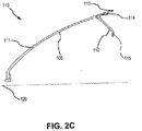
FIG. 2C illustrates a cross-section view of a nose cone, in accordance with various embodiments; -
FIG. 2D illustrates a cross-section view of a nose cone attached to a fan section, in accordance with various embodiments; -
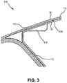
FIG. 3 illustrates a cross-section view of a nose cone having a repaired edge, in accordance with various embodiments; -
FIG. 4 illustrates a cross-section view of a nose cone having a first layer and a second layer located on an aft edge, in accordance with various embodiments; -
FIG. 5 illustrates an aft view of a nose cone having a spot face trimmed into a first layer and a second layer located on an aft edge, in accordance with various embodiments; and -
FIG. 6 illustrates a method for nose cone edge delamination repair, in accordance with various embodiments. - Elements and steps in the figures are illustrated for simplicity and clarity and have not necessarily been rendered according to any particular sequence. For example, steps that may be performed concurrently or in different order are illustrated in the figures to help to improve understanding of embodiments of the present disclosure.
- The detailed description of exemplary embodiments herein makes reference to the accompanying drawings, which show exemplary embodiments by way of illustration. While these exemplary embodiments are described in sufficient detail to enable those skilled in the art to practice the disclosures, it should be understood that other embodiments may be realized and that logical changes and adaptations in design and construction may be made in accordance with this disclosure and the teachings herein. Thus, the detailed description herein is presented for purposes of illustration only and not of limitation.
- The scope of the disclosure is defined by the appended claims and their legal equivalents rather than by merely the examples described. For example, the steps recited in any of the method or process descriptions may be executed in any order and are not necessarily limited to the order presented. Furthermore, any reference to singular includes plural embodiments, and any reference to more than one component or step may include a singular embodiment or step. Also, any reference to attached, fixed, coupled, connected or the like may include permanent, removable, temporary, partial, full and/or any other possible attachment option. Additionally, any reference to without contact (or similar phrases) may also include reduced contact or minimal contact. Surface shading lines may be used throughout the figures to denote different parts but not necessarily to denote the same or different materials.
- As used herein, "aft" refers to the direction associated with the tail (e.g., the back end) of an aircraft, or generally, to the direction of exhaust of the gas turbine engine. As used herein, "forward" refers to the direction associated with the nose (e.g., the front end) of an aircraft, or generally, to the direction of flight or motion.
- In various embodiments, and with reference to
FIG. 1A , a gas turbine engine 100 (such as a turbofan gas turbine engine) is illustrated.Gas turbine engine 100 is disposed aboutaxial centerline axis 120, which may also be referred to as axis ofrotation 120.Gas turbine engine 100 may comprise afan section 140,compressor sections combustion section 180, andturbine sections fan section 140 may drive air intocompressor sections combustion section 180. Air compressed in thecompressor sections combustion section 180 and expanded across theturbine sections turbine sections high pressure rotors 192 andlow pressure rotors 194, which rotate in response to the expansion. Theturbine sections blades 196 and static airfoils orvanes 198, housed within anengine casing 195. Cooling air may be supplied to theturbine sections compressor sections bearings 193 may support spools in thegas turbine engine 100.FIG. 1A provides a general understanding of the sections in a gas turbine engine, and is not intended to limit the disclosure. The present disclosure may extend to all types of applications and to all types of turbine engines, including turbofan gas turbine engines and turbojet engines. - In various embodiments, and with reference to
FIG. 1B , a perspective view of a front portion ofgas turbine engine 100 is depicted in greater detail.Gas turbine engine 100 may comprisenacelle 101,fan section 140, andnose cone 110.Fan section 140 may comprise a plurality of circumferentially arrangedfan blades 142.Fan platforms 144, or spacers, may be arranged betweenadjacent fan blades 142.Fan blades 142 may be mounted to afan hub 102 located radially inward offan platforms 144.Nose cone 110 may be arranged forward offan blades 142 to provide an aerodynamic flow path throughfan section 140 along withfan platforms 144. - In various embodiments, and with reference to
FIGs. 2A, 2B , and2C ,nose cone 110 is depicted in greater detail.Nose cone 110 may comprise anouter skirt 111 configured to aid in providing the aerodynamic flow path through fan section 140 (with brief reference toFIGs. 1A and1B ). In that regard,outer skirt 111 may comprise any suitable shape capable of aiding aerodynamic flow, such as, for example, a conical shape. In various embodiments,outer skirt 111 may comprise any suitable material. For example,outer skirt 111 may comprise a synthetic fiber having high-tensile strength, such as an aramid fiber (e.g., Kevlar®) and/or the like. In various embodiments,outer skirt 111 may comprise various layers of aramid fiber (e.g., Kevlar®), and/or other suitable material, placed on top of one another to formouter skirt 111.Outer skirt 111 may comprise any suitable number of layers, such as, for example, one layer to forty layers, twenty layers to forty layers, and/or any other suitable number of layers. In various embodiments, the number of layers may be dependent on desired operational factors such as weight, strength, and/or the like. In various embodiments,outer skirt 111 may comprise twenty layers of material. - In various embodiments,
outer skirt 111 may comprise an axiallyinner surface 105 and anaft edge 113.Aft edge 113 may comprise the aft end ofouter skirt 111. In various embodiments,nose cone 110 may comprise aflange 112 configured to couplenose cone 110 to a fan hub (e.g.,fan hub 102 inFIG. 2D ).Flange 112 may be coupled to axiallyinner surface 105 ofouter skirt 111, and may extend in an axially inward direction (in regard to axis 120).Flange 112 may couple to the fan hub using any suitable technique, such as, for example through a bolt (e.g., as depicted inFIG. 2D ), screw, fastener, and/or the like. In this regard,flange 112 may comprise aflange aperture 115 configured to receive a bolt, screw, fastener, and/or the like to coupleflange 112 to the fan hub. - In various embodiments,
nose cone 110 may comprise a pin landing 114 coupled to axiallyinner surface 105 ofouter skirt 111, aft offlange 112. With reference toFIG. 2D , afan platform pin 50 may be configured to couplefan platform 144 tofan hub 102.Fan platform pin 50 may be passed throughfan hub 102 andfan platform 144 to couplefan platform 144 tofan hub 102. In response tonose cone 110 being attached tofan hub 102, pin landing 114 may be configured to retainfan platform pin 50 from sliding forward during operation. In that regard, pin landing 114 may comprise any suitable shape capable of helping holdfan platform pin 50 into position. For example, pin landing 114 may comprise a triangular shape such thatfan platform pin 50 may abut an aft surface of pin landing 114 in response tonose cone 110 being attached tofan hub 102. - In various embodiments, and with reference to
FIG. 3 , anose cone 310 comprising a repairededge 316 is depicted. During repair and/or maintenance ofnose cone 310, and/or during operation of the engine, aftedge 113 may begin to delaminate. To repair delamination toaft edge 113, an epoxy resin, and/or the like, may be introduced into a delaminated material. The delaminated material may be clamped together and cured. A portion ofaft edge 113 may be cut away fromnose cone 310 to form repairededge 316. In various embodiments, repairededge 316 may be formed to allow for lower tolerances after repair, such as in response to a coupling of a first layer and a second layer (e.g.,first layer 417 andsecond layer 418, with reference toFIG. 4 ) tonose cone 310 during repair. For example, repairededge 316 may be formed such that the relative dimensions ofnose cone 310 after the coupling offirst layer 417 andsecond layer 418 during repair are substantially the same as the relative dimensions ofnose cone 310 prior to forming repairededge 316. - In that regard, and in various embodiments, the portion of
aft edge 113 cut away to form repairededge 316 may comprise a distance substantially equal to a thickness of the first layer and the second layer. For example, and with reference toFIG. 3 andFIG. 4 , wherefirst layer 417 comprises a thickness of about 0.01 inches (0.254 mm) andsecond layer 418 comprises a thickness of about 0.01 inches (0.254 mm), about 0.02 inches (0.508 mm) to about 0.025 inches (0.635 mm), or about 0.25 inches (0.635 mm) to about 0.03 inches (0.76 mm) may be cut fromaft edge 113 to form repaired edge 316 (wherein about in this context refers only to +/- 0.005 inches (0.127 mm)). In various embodiments, the portion ofaft edge 113 cut away to form repairededge 316 may also comprise a distance substantially equal to a thickness of a film adhesive, epoxy, and/or the like used to couplefirst layer 417 andsecond layer 418 to nose cone 310 (e.g., in a pre-impregnated method of formation). For example, where the film adhesive, epoxy, and/or the like comprises a thickness of about 0.01 inches (0.254 mm), about 0.03 inches (0.762 mm) to about 0.035 inches (0.889 mm), or about 0.035 inches (0.889 mm) to about 0.04 inches (1.02 mm) may be cut fromaft edge 113 to form repaired edge 316 (wherein about in this context refers only to +/- 0.005 inches (0.127 mm)). In various embodiments, the portion ofaft edge 113 cut away to form repairededge 316 may also comprise any other suitable and/or desired distance. - In various embodiments, repaired
edge 316 may comprise afirst edge 36 and asecond edge 35. In response to the delaminated material being repaired and repairededge 316 being formed,first edge 36 andsecond edge 35 may be substantially perpendicular with each other, such that repairededge 316 comprises substantially no delaminated material. - In various embodiments, aft
edge 113 may be cut using any suitable technique. For example, aftedge 113 may be cut using a milling machine, such as a horizontal mill. In various embodiments, in response to a large portion of the entire circumferential surface area ofaft edge 113 comprising delaminated material, such as, for example, about 50%, about 60%, or about 70% of the circumferential surface area of aft edge 113 (wherein about in this context refers only to +/- 5%), a lathe may be used to cut a larger surface area fromaft edge 113. In various embodiments, any other suitable cutting technique may also be used to cutaft edge 113. - In various embodiments, and with reference to
FIG. 4 , anose cone 410 comprising afirst layer 417 and asecond layer 418 is disclosed.First layer 417 may be configured to couple ontoouter skirt 111 and wrap around repairededge 316 andpin landing 114. In this regard,first layer 417 may cover an area of repairededge 316 where the delaminated material fromaft edge 113 was repaired and removed to strengthen and help protect against future delamination.Second layer 418 may be configured to couple ontofirst layer 417 andouter skirt 111, and extend pastfirst layer 417 in radial and axial directions. In that regard,second layer 418 may help holdfirst layer 417 into place and further strengthen repairededge 316 to protect against future delamination. In various embodiments,first layer 417 andsecond layer 418 may comprise any suitable fibrous material, such as, for example, aramid fiber (e.g., Kevlar®), fiberglass, carbon fiber, and/or the like. In various embodiments,first layer 417 andsecond layer 418 may also comprise any suitable thickness. - In various embodiments,
first layer 417 andsecond layer 418 may be formed using any suitable technique. In this regard, and in various embodiments,first layer 417 andsecond layer 418 may be formed by a wet layup method. In a wet layup method, resin may be introduced and cured ontoouter skirt 111 at repairededge 316.First layer 417 may be impregnated with resin and placed into position onouter skirt 111 at repairededge 316, on top of the cured resin.Second layer 418 may be impregnated with resin and placed into position overfirst layer 417 andouter skirt 111. Pressure may then be applied tofirst layer 417 andsecond layer 418, via clamps, a vacuum bag, and/or the like, andfirst layer 417 andsecond layer 418 may be cured to complete the wet layup process. In various embodiments,first layer 417 andsecond layer 418 may also be formed by a pre-impregnation method. As used herein, the term "pre-impregnated" may refer to fibrous structures, having, for example, glass fibers, carbon fibers, aramid fibers, and/or the like, pre-impregnated with an uncured or at least partially uncured matrix material, such as a resin, where the substantial majority of fibers are generally completely encased in the matrix material. In that regard,first layer 417 andsecond layer 418 may be pre-impregnated with an uncured or at least partially uncured matrix material and laid on a mold to form a desired shape.First layer 417 andsecond layer 418 may then be cured to form the shape.First layer 417 andsecond layer 418 may be placed onto repairededge 316 and coupled to repairededge 316 andouter skirt 111 using an epoxy resin, and/or the like. - In various embodiments,
first layer 417 may comprise any suitable size to cover repairededge 316.First layer 417 may cover repairededge 316 and extend ontoouter skirt 111 and pin landing 114 at a distance D1. Distance D1 may comprise any suitable size. For example, distance D1 may be based on an interlaminar shear strength offirst layer 417, taking into consideration factors such as the tensile strength of the fibrous material, the thickness of the fibrous material, the shear strength of the resin used to curefirst layer 417, and/or the like. Distance D1 may also be based on desired weight calculations, as a greater distance D1 adds more weight to nose cone 410 (i.e., a greater distance D1 would be associated with greater material from first layer 417). In various embodiments, distance D1 may be about 0.05 inches (1.27 mm) to about 2.0 inches (50.8 mm), about 0.2 inches (5.1 mm) to about 2.0 inches (50.8 mm), about 0.4 inches (10.2 mm) to about 2.0 inches (50.8 mm), about 0.7 inches (17.8 mm) to about 2.0 inches (50.8 mm), or about 1.0 inches (25.4 mm) to about 2.0 inches (50.8 mm) (wherein about in this context refers only to +/- 0.05 inches (1.27 mm)). In various embodiments, distance D1 may be 0.5 inches (12.7 mm) (wherein about in this context refers only to +/- 0.05 inches (1.27 mm)). - In various embodiments,
second layer 418 may comprise any suitable size to cover and/or extend pastfirst layer 417. For example,second layer 418 may extend pastfirst layer 417 at a distance D2. In various embodiments, distance D2 may comprise an equal distance with distance D1. For example, where distance D1 comprises 0.5 inches (12.7 mm), distance D2 may also comprise 0.5 inches (12.7 mm). Distance D2 may also be based on an interlaminar shear strength ofsecond layer 418, and/or desired weight calculations fornose cone 410. Distance D2 may also comprise any other suitable size, such as, for example, about 0.05 inches (1.27 mm) to about 2.0 inches (50.8 mm), about 0.2 inches (5.1 mm) to about 2.0 inches (50.8 mm), about 0.4 inches (10.2 mm) to about 2.0 inches (50.8 mm), about 0.7 inches (17.8 mm) to about 2.0 inches (50.8 mm), or about 1.0 inches (25.4 mm) to about 2.0 inches (50.8 mm) (wherein about in this context refers only to +/- 0.05 inches (1.27 mm)). In various embodiments, distance D2 may be 0.5 inches (12.7 mm) (wherein about in this context refers only to +/- 0.05 inches (1.27 mm)). - In various embodiments, and with reference to
FIG. 5 ,first layer 417 andsecond layer 418 may comprise aspot face 519.Spot face 519 may be configured to enable lower tolerances in response tonose cone 510 coupling to a fan hub. For example, and with brief reference toFIG. 2D , in response tonose cone 110 coupling tofan hub 102,fan platform pin 50 may abut pin landing 114. Withfirst layer 417 andsecond layer 418 installed onto repairededge 316 and pin landing 114,fan platform pin 50 may be forced into contact withsecond layer 418. In that regard,spot face 519 may comprise a void defined byfirst layer 417 andsecond layer 418, that is cut away to allow for lower tolerances between pin landing 114 andfan platform pin 50. - In various embodiments,
spot face 519 may comprise any suitable size to allow for lower tolerances, such as, for example, a distance D3. Distance D3 may comprise any suitable shape and/or desired size, such as the diameter offan platform pin 50. In that regard, distance D3 may be about 0.3 inches (7.6 mm) to about 0.8 inches (20.3 mm), or about 0.5 inches (12.7 mm) to about 0.8 inches (20.3 mm) (wherein about in this context refers to only +/- 0.05 inches (1.27 mm)). In various embodiments,spot face 519 may be cut from offirst layer 417 andsecond layer 418 prior to curingfirst layer 417 andsecond layer 418.Spot face 519 may also be cut using any suitable technique, such as, for example, via a computer-aided milling machine, and/or the like. In various embodiments,spot face 519 may also be cut from any other suitable position onfirst layer 417 andsecond layer 418 where a lower tolerance may be desired. - In various embodiments, and with reference to
FIG. 6 , amethod 600 for nose cone edge delamination repair is disclosed.Method 600 may enable repair of nose cone edge delamination, while also optimizing strength in the repair and maintaining fit and tolerances to mating parts. In various embodiments, and with reference toFIGs. 3 and6 ,method 600 may comprise trimming aft edge 113 (Step 602). Step 602 may also comprise removing erosion resistance material on the surface ofouter skirt 111, cleaning the surface of outer skirt 111 (e.g., using a solvent such as isopropyl alcohol, and/or the like), and evaluating the extent of delamination. Evaluating the extent of delamination may comprise performing a tap test on the surface of outer skirt 111 (e.g., tapping a solid object on the surface ofouter skirt 111 to listen for differences in the sound produced). Step 602 may also comprise filling the delaminated area with an epoxy, clamping the delaminated area, and curing the delaminated area. Trimmingaft edge 113 may comprise trimming a portion ofaft edge 113 to form repairededge 316.Aft edge 113 may be trimmed using any suitable technique discussed herein and/or known in the art. - In various embodiments, and with reference to
FIGs. 4 and6 ,method 600 may comprise formingfirst layer 417 onto repaired edge 316 (Step 604). Step 604 may comprise formingfirst layer 417 onto repairededge 316, and extendingfirst layer 417 to cover a portion ofouter skirt 111 andpin landing 114.First layer 417 may extend overouter skirt 111 and pin landing 114 at distance D1. In various embodiments,Step 604 may comprise formingfirst layer 417 using a wet layup method. In various embodiments,Step 604 may comprise formingfirst layer 417 using a pre-impregnated method. - In various embodiments,
method 600 may comprise formingsecond layer 418 ontofirst layer 417 and repaired edge 316 (Step 606). Step 606 may comprise formingsecond layer 418 on top offirst layer 417 to extend pastfirst layer 417 at a distance D2. In various embodiments,Step 606 may comprise formingsecond layer 418 using a wet layup method. In various embodiments,Step 606 may comprise formingsecond layer 418 using a pre-impregnated method. - In various embodiments, and with reference to
FIGs. 5 and6 ,method 600 may comprise trimmingfirst layer 417 andsecond layer 418 to form spot face 519 (Step 608). Step 608 may comprise trimmingfirst layer 417 andsecond layer 418 at a location where a lower tolerance may be desired, such as, for example, onpin landing 114. Step 608 may comprise trimmingfirst layer 417 andsecond layer 418 to formspot face 519 having a diameter of distance D3. In various embodiments,Step 608 may also comprise curingfirst layer 417 andsecond layer 418. Step 608 may also comprise pressurizing (via clamps, a vacuum bag, and/or the like),first layer 417 andsecond layer 418 prior to curing. Step 608 may also comprise removing unwanted resin, cleaning the surface area offirst layer 417 andsecond layer 418, and checking repaired edge 316 (e.g., visually and/or through a tap test). Step 608 may also comprise applying a protective coating to the axially outer surfaces offirst layer 417 andsecond layer 418, such as, for example, an erosion resistant coating, a polytetrafluoroethylene coating (e.g., Teflon® coating), polymer, ceramic, plastic, and/or any other protective material. - Benefits, other advantages, and solutions to problems have been described herein with regard to specific embodiments. Furthermore, the connecting lines shown in the various figures contained herein are intended to represent exemplary functional relationships and/or physical couplings between the various elements. It should be noted that many alternative or additional functional relationships or physical connections may be present in a practical system. However, the benefits, advantages, solutions to problems, and any elements that may cause any benefit, advantage, or solution to occur or become more pronounced are not to be construed as critical, required, or essential features or elements of the disclosures. The scope of the disclosures is accordingly to be limited by nothing other than the appended claims and their legal equivalents, in which reference to an element in the singular is not intended to mean "one and only one" unless explicitly so stated, but rather "one or more." Moreover, where a phrase similar to "at least one of A, B, or C" is used in the claims, it is intended that the phrase be interpreted to mean that A alone may be present in an embodiment, B alone may be present in an embodiment, C alone may be present in an embodiment, or that any combination of the elements A, B and C may be present in a single embodiment; for example, A and B, A and C, B and C, or A and B and C.
- Systems, methods and apparatus are provided herein. In the detailed description herein, references to "various embodiments", "one embodiment", "an embodiment", "an example embodiment", etc., indicate that the embodiment described may include a particular feature, structure, or characteristic, but every embodiment may not necessarily include the particular feature, structure, or characteristic. Moreover, such phrases are not necessarily referring to the same embodiment. Further, when a particular feature, structure, or characteristic is described in connection with an embodiment, it is submitted that it is within the knowledge of one skilled in the art to affect such feature, structure, or characteristic in connection with other embodiments whether or not explicitly described. After reading the description, it will be apparent to one skilled in the relevant art(s) how to implement the disclosure in alternative embodiments.
- As used herein, the terms "comprises", "comprising", or any other variation thereof, are intended to cover a non-exclusive inclusion, such that a process, method, article, or apparatus that comprises a list of elements does not include only those elements but may include other elements not expressly listed or inherent to such process, method, article, or apparatus.
Claims (15)
- A nose cone (110;310), comprising:an outer skirt (111) having an axially inner surface (105) opposite an axially outer surface, and a repaired edge (316) having a first edge (36) and a second edge (35), wherein the first edge (36) is substantially perpendicular with the second edge (35);a pin landing (114) coupled to the axially inner surface (105) near the repaired edge (316);a first layer (417) coupled to the repaired edge (316) and having a first end and a second end, wherein the first end extends in an axial direction past the repaired edge (316) and onto the axially outer surface of the outer skirt (111), and wherein the second end extends in the axial direction past the repaired edge (316) and onto the pin landing (114); anda second layer (418) coupled to the first layer (417) and having a third edge and a fourth edge, wherein the third edge of the second layer (418) extends past the first end of the first layer (417) and the fourth edge of the second layer (418) extends past the second end of the first layer (417).
- The nose cone of claim 1, further comprising a spot face (519) located on the second layer (418) and the first layer (417) proximate the pin landing (114), wherein the spot face (519) is bounded by the second layer (418) and the first layer (417).
- The nose cone of claim 1 or 2, further comprising a flange (112) coupled to the axially inner surface (105) of the outer skirt (111) forward the pin landing (114).
- The nose cone of any preceding claim, wherein the first end of the first layer (417) extends in the axial direction past the repaired edge (316) and onto the axially outer surface of the outer skirt (111) at a first distance (D1), and wherein the second end of the first layer (418) extends in the axial direction past the repaired edge (316) and onto the pin landing (114) at the first distance (D1).
- The nose cone of claim 4, wherein the third edge of the second layer (418) extends past the first end of the first layer (417) at a second distance (D2), wherein the fourth edge of the second layer (418) extends past the second end of the first layer (417) at the second distance (D2), and wherein the second distance (D2) is equal to the first distance (D1).
- The nose cone of claim 4 or 5, wherein the first distance (D1) is from about 0.05 inches (1.27 mm) to about 2.0 inches (50.8 mm).
- A method, comprising:trimming an aft edge (113) of an outer skirt (111) of a nose cone (110;310) to form a repaired edge (316);placing a first layer (417) onto the repaired edge (316);placing a second layer (418) on top of the first layer (417), wherein the second layer (418) extends past the first layer (417); andtrimming the first layer (417) and the second layer (418) to form a spot face (519).
- The method of claim 7, further comprising forming the first layer (417) and the second layer (418) using a wet layup method.
- The method of claim 7, further comprising forming the first layer (417) and the second layer (418) using a pre-impregnated method.
- The method of claim 8 or 9, further comprising extending the first layer (417) in an axial direction onto the outer skirt (111) at a first distance (D1), and extending the first layer (417) in the axial direction onto a pin landing (114) at the first distance (D1).
- The method of claim 10, further comprising extending the second layer (418) in the axial direction to extend past the first layer (417) at a second distance (D2), wherein the second distance (D2) is equal to the first distance (D1).
- The method of claim 10 or 11, further comprising extending the first layer (417) at the first distance (D1) of about 0.05 inches (1.27 mm) to about 2.0 inches (50.8 mm).
- The method of any of claims 7 to 12, further comprising applying a protective coating over the first layer (417) and the second layer (418).
- A fan section (140) for a gas turbine engine (100), comprising:a fan hub (102);a plurality of fan blades (142) coupled to the fan hub (102); andthe nose cone of any of claims 1 to 6 coupled to the fan hub (102) forward of the plurality of fan blades (142).
- The fan section of claim 14, further comprising a plurality of fan platforms (144) coupled to the fan hub (102) using a fan platform pin (50), wherein, optionally, the fan platform pin (50) abuts the pin landing (114) at a location of a/the spot face (519).
Applications Claiming Priority (1)
| Application Number | Priority Date | Filing Date | Title |
|---|---|---|---|
| US15/162,104 US10207792B2 (en) | 2016-05-23 | 2016-05-23 | System and method for nose cone edge delamination repair |
Publications (2)
| Publication Number | Publication Date |
|---|---|
| EP3249163A1 true EP3249163A1 (en) | 2017-11-29 |
| EP3249163B1 EP3249163B1 (en) | 2020-01-08 |
Family
ID=58772720
Family Applications (1)
| Application Number | Title | Priority Date | Filing Date |
|---|---|---|---|
| EP17172282.0A Active EP3249163B1 (en) | 2016-05-23 | 2017-05-22 | System and method for nose cone edge delamination repair |
Country Status (2)
| Country | Link |
|---|---|
| US (1) | US10207792B2 (en) |
| EP (1) | EP3249163B1 (en) |
Cited By (1)
| Publication number | Priority date | Publication date | Assignee | Title |
|---|---|---|---|---|
| EP4163474A3 (en) * | 2021-10-08 | 2023-07-12 | Raytheon Technologies Corporation | Method of repairing a coated inter-blade platform |
Families Citing this family (2)
| Publication number | Priority date | Publication date | Assignee | Title |
|---|---|---|---|---|
| US11078839B2 (en) * | 2018-01-22 | 2021-08-03 | Rolls-Royce Corporation | Composite nosecone |
| US11873835B2 (en) * | 2021-03-31 | 2024-01-16 | Stokes Technology Development Ltd. | Manufacturing method of axial air moving device with blades overlapped in axial projection |
Citations (3)
| Publication number | Priority date | Publication date | Assignee | Title |
|---|---|---|---|---|
| US5833435A (en) * | 1996-12-24 | 1998-11-10 | United Technologies Corporation | Inlet nose cone assembly and method for repairing the assembly |
| EP1775445A2 (en) * | 2005-10-11 | 2007-04-18 | United Technologies Corporation | Method of repair for inlet caps of turbine engines |
| US20070234544A1 (en) * | 2006-03-30 | 2007-10-11 | United Technologies Corporation | Fabric bushing installation to repair a hole |
Family Cites Families (8)
| Publication number | Priority date | Publication date | Assignee | Title |
|---|---|---|---|---|
| US2401247A (en) * | 1941-09-20 | 1946-05-28 | Goodrich Co B F | Spinner assembly |
| GB0102169D0 (en) * | 2001-01-27 | 2001-03-14 | Rolls Royce Plc | A gas turbine engine nose cone |
| GB2398353B (en) * | 2003-02-14 | 2006-02-15 | Rolls Royce Plc | A gas turbine engine nose cone |
| US7575417B2 (en) * | 2003-09-05 | 2009-08-18 | General Electric Company | Reinforced fan blade |
| US8206096B2 (en) * | 2009-07-08 | 2012-06-26 | General Electric Company | Composite turbine nozzle |
| US8449260B2 (en) * | 2009-10-30 | 2013-05-28 | General Electric Company | Composite load-bearing rotating ring and process therefor |
| GB201005053D0 (en) * | 2010-03-26 | 2010-05-12 | Rolls Royce Plc | A gas turbine engine nose cone |
| US9539767B2 (en) * | 2014-12-05 | 2017-01-10 | The Boeing Company | Forming of staged thermoset composite materials |
-
2016
- 2016-05-23 US US15/162,104 patent/US10207792B2/en active Active
-
2017
- 2017-05-22 EP EP17172282.0A patent/EP3249163B1/en active Active
Patent Citations (3)
| Publication number | Priority date | Publication date | Assignee | Title |
|---|---|---|---|---|
| US5833435A (en) * | 1996-12-24 | 1998-11-10 | United Technologies Corporation | Inlet nose cone assembly and method for repairing the assembly |
| EP1775445A2 (en) * | 2005-10-11 | 2007-04-18 | United Technologies Corporation | Method of repair for inlet caps of turbine engines |
| US20070234544A1 (en) * | 2006-03-30 | 2007-10-11 | United Technologies Corporation | Fabric bushing installation to repair a hole |
Cited By (1)
| Publication number | Priority date | Publication date | Assignee | Title |
|---|---|---|---|---|
| EP4163474A3 (en) * | 2021-10-08 | 2023-07-12 | Raytheon Technologies Corporation | Method of repairing a coated inter-blade platform |
Also Published As
| Publication number | Publication date |
|---|---|
| EP3249163B1 (en) | 2020-01-08 |
| US10207792B2 (en) | 2019-02-19 |
| US20170334547A1 (en) | 2017-11-23 |
Similar Documents
| Publication | Publication Date | Title |
|---|---|---|
| US8046915B2 (en) | Methods for making composite containment casings | |
| US8061966B2 (en) | Composite containment casings | |
| US10450870B2 (en) | Frangible gas turbine engine airfoil | |
| US8371009B2 (en) | Methods for repairing composite containment casings | |
| US10221718B2 (en) | Fan cases and manufacture methods | |
| US9482095B2 (en) | Web connected dual aerofoil members | |
| US10731662B2 (en) | Apparatus and method of manufacturing a containment case with embedded containment core | |
| US20200024958A1 (en) | Method of manufacturing a fan blade and a fan blade | |
| US11725524B2 (en) | Engine airfoil metal edge | |
| US10519965B2 (en) | Method and system for fiber reinforced composite panels | |
| US20170101878A1 (en) | Low modulus insert for a component of a gas turbine engine | |
| US10907651B2 (en) | Fan track liner subassembly angled upturn joint | |
| EP3249163B1 (en) | System and method for nose cone edge delamination repair | |
| US9040138B2 (en) | Composite article including composite to metal interlock and method of fabrication | |
| CN104661803A (en) | Method and system for fabricating composite containment casings | |
| CN115217627A (en) | Airfoils for Gas Turbine Engines | |
| US12338747B2 (en) | Turbine engine with composite airfoils | |
| US11549391B2 (en) | Component formed from hybrid material | |
| US20250121570A1 (en) | Method for repairing composite laminate material component | |
| GB2485137A (en) | Composite structure manufactured using modular moulds |
Legal Events
| Date | Code | Title | Description |
|---|---|---|---|
| PUAI | Public reference made under article 153(3) epc to a published international application that has entered the european phase |
Free format text: ORIGINAL CODE: 0009012 |
|
| STAA | Information on the status of an ep patent application or granted ep patent |
Free format text: STATUS: THE APPLICATION HAS BEEN PUBLISHED |
|
| AK | Designated contracting states |
Kind code of ref document: A1 Designated state(s): AL AT BE BG CH CY CZ DE DK EE ES FI FR GB GR HR HU IE IS IT LI LT LU LV MC MK MT NL NO PL PT RO RS SE SI SK SM TR |
|
| AX | Request for extension of the european patent |
Extension state: BA ME |
|
| STAA | Information on the status of an ep patent application or granted ep patent |
Free format text: STATUS: REQUEST FOR EXAMINATION WAS MADE |
|
| 17P | Request for examination filed |
Effective date: 20180525 |
|
| RBV | Designated contracting states (corrected) |
Designated state(s): AL AT BE BG CH CY CZ DE DK EE ES FI FR GB GR HR HU IE IS IT LI LT LU LV MC MK MT NL NO PL PT RO RS SE SI SK SM TR |
|
| GRAP | Despatch of communication of intention to grant a patent |
Free format text: ORIGINAL CODE: EPIDOSNIGR1 |
|
| STAA | Information on the status of an ep patent application or granted ep patent |
Free format text: STATUS: GRANT OF PATENT IS INTENDED |
|
| INTG | Intention to grant announced |
Effective date: 20190801 |
|
| GRAS | Grant fee paid |
Free format text: ORIGINAL CODE: EPIDOSNIGR3 |
|
| GRAA | (expected) grant |
Free format text: ORIGINAL CODE: 0009210 |
|
| STAA | Information on the status of an ep patent application or granted ep patent |
Free format text: STATUS: THE PATENT HAS BEEN GRANTED |
|
| AK | Designated contracting states |
Kind code of ref document: B1 Designated state(s): AL AT BE BG CH CY CZ DE DK EE ES FI FR GB GR HR HU IE IS IT LI LT LU LV MC MK MT NL NO PL PT RO RS SE SI SK SM TR |
|
| REG | Reference to a national code |
Ref country code: GB Ref legal event code: FG4D |
|
| REG | Reference to a national code |
Ref country code: CH Ref legal event code: EP |
|
| REG | Reference to a national code |
Ref country code: DE Ref legal event code: R096 Ref document number: 602017010555 Country of ref document: DE |
|
| REG | Reference to a national code |
Ref country code: IE Ref legal event code: FG4D |
|
| REG | Reference to a national code |
Ref country code: AT Ref legal event code: REF Ref document number: 1222965 Country of ref document: AT Kind code of ref document: T Effective date: 20200215 |
|
| REG | Reference to a national code |
Ref country code: NL Ref legal event code: MP Effective date: 20200108 |
|
| REG | Reference to a national code |
Ref country code: LT Ref legal event code: MG4D |
|
| PG25 | Lapsed in a contracting state [announced via postgrant information from national office to epo] |
Ref country code: PT Free format text: LAPSE BECAUSE OF FAILURE TO SUBMIT A TRANSLATION OF THE DESCRIPTION OR TO PAY THE FEE WITHIN THE PRESCRIBED TIME-LIMIT Effective date: 20200531 Ref country code: RS Free format text: LAPSE BECAUSE OF FAILURE TO SUBMIT A TRANSLATION OF THE DESCRIPTION OR TO PAY THE FEE WITHIN THE PRESCRIBED TIME-LIMIT Effective date: 20200108 Ref country code: FI Free format text: LAPSE BECAUSE OF FAILURE TO SUBMIT A TRANSLATION OF THE DESCRIPTION OR TO PAY THE FEE WITHIN THE PRESCRIBED TIME-LIMIT Effective date: 20200108 Ref country code: NO Free format text: LAPSE BECAUSE OF FAILURE TO SUBMIT A TRANSLATION OF THE DESCRIPTION OR TO PAY THE FEE WITHIN THE PRESCRIBED TIME-LIMIT Effective date: 20200408 Ref country code: NL Free format text: LAPSE BECAUSE OF FAILURE TO SUBMIT A TRANSLATION OF THE DESCRIPTION OR TO PAY THE FEE WITHIN THE PRESCRIBED TIME-LIMIT Effective date: 20200108 Ref country code: LT Free format text: LAPSE BECAUSE OF FAILURE TO SUBMIT A TRANSLATION OF THE DESCRIPTION OR TO PAY THE FEE WITHIN THE PRESCRIBED TIME-LIMIT Effective date: 20200108 |
|
| PG25 | Lapsed in a contracting state [announced via postgrant information from national office to epo] |
Ref country code: BG Free format text: LAPSE BECAUSE OF FAILURE TO SUBMIT A TRANSLATION OF THE DESCRIPTION OR TO PAY THE FEE WITHIN THE PRESCRIBED TIME-LIMIT Effective date: 20200408 Ref country code: LV Free format text: LAPSE BECAUSE OF FAILURE TO SUBMIT A TRANSLATION OF THE DESCRIPTION OR TO PAY THE FEE WITHIN THE PRESCRIBED TIME-LIMIT Effective date: 20200108 Ref country code: SE Free format text: LAPSE BECAUSE OF FAILURE TO SUBMIT A TRANSLATION OF THE DESCRIPTION OR TO PAY THE FEE WITHIN THE PRESCRIBED TIME-LIMIT Effective date: 20200108 Ref country code: IS Free format text: LAPSE BECAUSE OF FAILURE TO SUBMIT A TRANSLATION OF THE DESCRIPTION OR TO PAY THE FEE WITHIN THE PRESCRIBED TIME-LIMIT Effective date: 20200508 Ref country code: GR Free format text: LAPSE BECAUSE OF FAILURE TO SUBMIT A TRANSLATION OF THE DESCRIPTION OR TO PAY THE FEE WITHIN THE PRESCRIBED TIME-LIMIT Effective date: 20200409 Ref country code: HR Free format text: LAPSE BECAUSE OF FAILURE TO SUBMIT A TRANSLATION OF THE DESCRIPTION OR TO PAY THE FEE WITHIN THE PRESCRIBED TIME-LIMIT Effective date: 20200108 |
|
| REG | Reference to a national code |
Ref country code: DE Ref legal event code: R097 Ref document number: 602017010555 Country of ref document: DE |
|
| PG25 | Lapsed in a contracting state [announced via postgrant information from national office to epo] |
Ref country code: DK Free format text: LAPSE BECAUSE OF FAILURE TO SUBMIT A TRANSLATION OF THE DESCRIPTION OR TO PAY THE FEE WITHIN THE PRESCRIBED TIME-LIMIT Effective date: 20200108 Ref country code: ES Free format text: LAPSE BECAUSE OF FAILURE TO SUBMIT A TRANSLATION OF THE DESCRIPTION OR TO PAY THE FEE WITHIN THE PRESCRIBED TIME-LIMIT Effective date: 20200108 Ref country code: SK Free format text: LAPSE BECAUSE OF FAILURE TO SUBMIT A TRANSLATION OF THE DESCRIPTION OR TO PAY THE FEE WITHIN THE PRESCRIBED TIME-LIMIT Effective date: 20200108 Ref country code: RO Free format text: LAPSE BECAUSE OF FAILURE TO SUBMIT A TRANSLATION OF THE DESCRIPTION OR TO PAY THE FEE WITHIN THE PRESCRIBED TIME-LIMIT Effective date: 20200108 Ref country code: CZ Free format text: LAPSE BECAUSE OF FAILURE TO SUBMIT A TRANSLATION OF THE DESCRIPTION OR TO PAY THE FEE WITHIN THE PRESCRIBED TIME-LIMIT Effective date: 20200108 Ref country code: SM Free format text: LAPSE BECAUSE OF FAILURE TO SUBMIT A TRANSLATION OF THE DESCRIPTION OR TO PAY THE FEE WITHIN THE PRESCRIBED TIME-LIMIT Effective date: 20200108 Ref country code: EE Free format text: LAPSE BECAUSE OF FAILURE TO SUBMIT A TRANSLATION OF THE DESCRIPTION OR TO PAY THE FEE WITHIN THE PRESCRIBED TIME-LIMIT Effective date: 20200108 |
|
| PLBE | No opposition filed within time limit |
Free format text: ORIGINAL CODE: 0009261 |
|
| STAA | Information on the status of an ep patent application or granted ep patent |
Free format text: STATUS: NO OPPOSITION FILED WITHIN TIME LIMIT |
|
| REG | Reference to a national code |
Ref country code: AT Ref legal event code: MK05 Ref document number: 1222965 Country of ref document: AT Kind code of ref document: T Effective date: 20200108 |
|
| 26N | No opposition filed |
Effective date: 20201009 |
|
| PG25 | Lapsed in a contracting state [announced via postgrant information from national office to epo] |
Ref country code: CH Free format text: LAPSE BECAUSE OF NON-PAYMENT OF DUE FEES Effective date: 20200531 Ref country code: MC Free format text: LAPSE BECAUSE OF FAILURE TO SUBMIT A TRANSLATION OF THE DESCRIPTION OR TO PAY THE FEE WITHIN THE PRESCRIBED TIME-LIMIT Effective date: 20200108 Ref country code: LI Free format text: LAPSE BECAUSE OF NON-PAYMENT OF DUE FEES Effective date: 20200531 Ref country code: IT Free format text: LAPSE BECAUSE OF FAILURE TO SUBMIT A TRANSLATION OF THE DESCRIPTION OR TO PAY THE FEE WITHIN THE PRESCRIBED TIME-LIMIT Effective date: 20200108 Ref country code: AT Free format text: LAPSE BECAUSE OF FAILURE TO SUBMIT A TRANSLATION OF THE DESCRIPTION OR TO PAY THE FEE WITHIN THE PRESCRIBED TIME-LIMIT Effective date: 20200108 |
|
| PG25 | Lapsed in a contracting state [announced via postgrant information from national office to epo] |
Ref country code: SI Free format text: LAPSE BECAUSE OF FAILURE TO SUBMIT A TRANSLATION OF THE DESCRIPTION OR TO PAY THE FEE WITHIN THE PRESCRIBED TIME-LIMIT Effective date: 20200108 Ref country code: PL Free format text: LAPSE BECAUSE OF FAILURE TO SUBMIT A TRANSLATION OF THE DESCRIPTION OR TO PAY THE FEE WITHIN THE PRESCRIBED TIME-LIMIT Effective date: 20200108 |
|
| REG | Reference to a national code |
Ref country code: BE Ref legal event code: MM Effective date: 20200531 |
|
| PG25 | Lapsed in a contracting state [announced via postgrant information from national office to epo] |
Ref country code: LU Free format text: LAPSE BECAUSE OF NON-PAYMENT OF DUE FEES Effective date: 20200522 |
|
| PG25 | Lapsed in a contracting state [announced via postgrant information from national office to epo] |
Ref country code: IE Free format text: LAPSE BECAUSE OF NON-PAYMENT OF DUE FEES Effective date: 20200522 |
|
| PG25 | Lapsed in a contracting state [announced via postgrant information from national office to epo] |
Ref country code: BE Free format text: LAPSE BECAUSE OF NON-PAYMENT OF DUE FEES Effective date: 20200531 |
|
| PG25 | Lapsed in a contracting state [announced via postgrant information from national office to epo] |
Ref country code: TR Free format text: LAPSE BECAUSE OF FAILURE TO SUBMIT A TRANSLATION OF THE DESCRIPTION OR TO PAY THE FEE WITHIN THE PRESCRIBED TIME-LIMIT Effective date: 20200108 Ref country code: MT Free format text: LAPSE BECAUSE OF FAILURE TO SUBMIT A TRANSLATION OF THE DESCRIPTION OR TO PAY THE FEE WITHIN THE PRESCRIBED TIME-LIMIT Effective date: 20200108 Ref country code: CY Free format text: LAPSE BECAUSE OF FAILURE TO SUBMIT A TRANSLATION OF THE DESCRIPTION OR TO PAY THE FEE WITHIN THE PRESCRIBED TIME-LIMIT Effective date: 20200108 |
|
| PG25 | Lapsed in a contracting state [announced via postgrant information from national office to epo] |
Ref country code: MK Free format text: LAPSE BECAUSE OF FAILURE TO SUBMIT A TRANSLATION OF THE DESCRIPTION OR TO PAY THE FEE WITHIN THE PRESCRIBED TIME-LIMIT Effective date: 20200108 Ref country code: AL Free format text: LAPSE BECAUSE OF FAILURE TO SUBMIT A TRANSLATION OF THE DESCRIPTION OR TO PAY THE FEE WITHIN THE PRESCRIBED TIME-LIMIT Effective date: 20200108 |
|
| REG | Reference to a national code |
Ref country code: DE Ref legal event code: R081 Ref document number: 602017010555 Country of ref document: DE Owner name: RAYTHEON TECHNOLOGIES CORPORATION (N.D.GES.D.S, US Free format text: FORMER OWNER: UNITED TECHNOLOGIES CORPORATION, FARMINGTON, CONN., US Ref country code: DE Ref legal event code: R081 Ref document number: 602017010555 Country of ref document: DE Owner name: RTX CORPORATION (N.D.GES.D. STAATES DELAWARE),, US Free format text: FORMER OWNER: UNITED TECHNOLOGIES CORPORATION, FARMINGTON, CONN., US |
|
| P01 | Opt-out of the competence of the unified patent court (upc) registered |
Effective date: 20230520 |
|
| PGFP | Annual fee paid to national office [announced via postgrant information from national office to epo] |
Ref country code: DE Payment date: 20250423 Year of fee payment: 9 |
|
| PGFP | Annual fee paid to national office [announced via postgrant information from national office to epo] |
Ref country code: GB Payment date: 20250423 Year of fee payment: 9 |
|
| PGFP | Annual fee paid to national office [announced via postgrant information from national office to epo] |
Ref country code: FR Payment date: 20250423 Year of fee payment: 9 |
|
| REG | Reference to a national code |
Ref country code: DE Ref legal event code: R081 Ref document number: 602017010555 Country of ref document: DE Owner name: RTX CORPORATION (N.D.GES.D. STAATES DELAWARE),, US Free format text: FORMER OWNER: RAYTHEON TECHNOLOGIES CORPORATION (N.D.GES.D.STAATES DELAWARE), ARLINGTON, VA, US |