EP3249142A1 - Covering device for a trunk of a motor vehicle - Google Patents
Covering device for a trunk of a motor vehicle Download PDFInfo
- Publication number
- EP3249142A1 EP3249142A1 EP16425046.6A EP16425046A EP3249142A1 EP 3249142 A1 EP3249142 A1 EP 3249142A1 EP 16425046 A EP16425046 A EP 16425046A EP 3249142 A1 EP3249142 A1 EP 3249142A1
- Authority
- EP
- European Patent Office
- Prior art keywords
- panel
- hinge
- spring
- hold
- retention
- Prior art date
- Legal status (The legal status is an assumption and is not a legal conclusion. Google has not performed a legal analysis and makes no representation as to the accuracy of the status listed.)
- Granted
Links
Images


Classifications
-
- E—FIXED CONSTRUCTIONS
- E05—LOCKS; KEYS; WINDOW OR DOOR FITTINGS; SAFES
- E05D—HINGES OR SUSPENSION DEVICES FOR DOORS, WINDOWS OR WINGS
- E05D11/00—Additional features or accessories of hinges
- E05D11/10—Devices for preventing movement between relatively-movable hinge parts
- E05D11/1028—Devices for preventing movement between relatively-movable hinge parts for maintaining the hinge in two or more positions, e.g. intermediate or fully open
- E05D11/1078—Devices for preventing movement between relatively-movable hinge parts for maintaining the hinge in two or more positions, e.g. intermediate or fully open the maintaining means acting parallel to the pivot
- E05D11/1085—Devices for preventing movement between relatively-movable hinge parts for maintaining the hinge in two or more positions, e.g. intermediate or fully open the maintaining means acting parallel to the pivot specially adapted for vehicles
-
- B—PERFORMING OPERATIONS; TRANSPORTING
- B60—VEHICLES IN GENERAL
- B60R—VEHICLES, VEHICLE FITTINGS, OR VEHICLE PARTS, NOT OTHERWISE PROVIDED FOR
- B60R13/00—Elements for body-finishing, identifying, or decorating; Arrangements or adaptations for advertising purposes
- B60R13/01—Liners for load platforms or load compartments
- B60R13/011—Liners for load platforms or load compartments for internal load compartments, e.g. car trunks
-
- B—PERFORMING OPERATIONS; TRANSPORTING
- B60—VEHICLES IN GENERAL
- B60R—VEHICLES, VEHICLE FITTINGS, OR VEHICLE PARTS, NOT OTHERWISE PROVIDED FOR
- B60R13/00—Elements for body-finishing, identifying, or decorating; Arrangements or adaptations for advertising purposes
- B60R13/01—Liners for load platforms or load compartments
- B60R2013/018—Connection or positioning of adjacent panels
-
- E—FIXED CONSTRUCTIONS
- E05—LOCKS; KEYS; WINDOW OR DOOR FITTINGS; SAFES
- E05D—HINGES OR SUSPENSION DEVICES FOR DOORS, WINDOWS OR WINGS
- E05D5/00—Construction of single parts, e.g. the parts for attachment
- E05D5/10—Pins, sockets or sleeves; Removable pins
- E05D2005/102—Pins
- E05D2005/106—Pins with non-cylindrical portions
-
- E—FIXED CONSTRUCTIONS
- E05—LOCKS; KEYS; WINDOW OR DOOR FITTINGS; SAFES
- E05Y—INDEXING SCHEME ASSOCIATED WITH SUBCLASSES E05D AND E05F, RELATING TO CONSTRUCTION ELEMENTS, ELECTRIC CONTROL, POWER SUPPLY, POWER SIGNAL OR TRANSMISSION, USER INTERFACES, MOUNTING OR COUPLING, DETAILS, ACCESSORIES, AUXILIARY OPERATIONS NOT OTHERWISE PROVIDED FOR, APPLICATION THEREOF
- E05Y2900/00—Application of doors, windows, wings or fittings thereof
- E05Y2900/50—Application of doors, windows, wings or fittings thereof for vehicles
- E05Y2900/53—Type of wing
- E05Y2900/538—Interior lids
Definitions
- the present invention relates to a covering device for a trunk of a motor vehicle.
- the trunk In motor vehicles, the trunk is usually provided with a loading floor defined by a rigid panel, which can be rotated between a horizontal lowered position, where it covers a bottom surface of the trunk, and a tilted raised position, where it gives access to an underlying space and/or to a spare wheel and/or to service tools housed beneath the loading floor.
- a loading floor defined by a rigid panel, which can be rotated between a horizontal lowered position, where it covers a bottom surface of the trunk, and a tilted raised position, where it gives access to an underlying space and/or to a spare wheel and/or to service tools housed beneath the loading floor.
- the loading floor has a front end coupled to the sides of the trunk, free to rotate between the two aforementioned positions.
- the panel supported by fixed shoulders in the trunk defines the horizontal lowered position. In the absence of any luggage, only the weight of the panel gives stability to this position, so that, when the car is in motion, some noise due to vibrations of the panel is usually coming from the trunk.
- the object of the present invention is to provide a covering device for a trunk of a motor vehicle, which solves in a simple and economic manner the aforesaid drawbacks.
- a covering device for a trunk of a motor vehicle is manufactured as defined in claim 1.
- the reference number 1 indicates a covering device arranged in a trunk 4 (partially shown) of a motor vehicle and comprising a rigid panel 5, which is rotatable about a horizontal hinge axis 6, orthogonal to a longitudinal axis 7 defining the direction of travel of the motor vehicle.
- the panel 5 has an upper surface 8 supporting the luggage or other objects, so that the device 1 defines a loading floor.
- the panel 5 is arranged in a reference lowered position, where it is substantially horizontal and has a lower surface 9 that covers a bottom 10 of the trunk floor 4. This latter may house a spare wheel and/or service tools and/or may define an additional support surface for small objects and/or luggage.
- the panel 5 can be spaced from the floor 10 and define, with this latter, an underlying space.
- the device 1 defines a parcel shelf of the trunk 4, instead of a loading floor.
- the panel 5 When it is rotated upward about the axis 6 by the user, the panel 5 comes to a reference raised position (in dotted line), where it is tilted so that the user can reach the objects arranged beneath the surface 9.
- the device 1 comprises a hinge 12 coupling a front end portion 13 of the panel 5 to a support body or structure 14 fixedly arranged in the trunk 4 (here and below, the terms “rear”, “front”, “front”, “forward”, “back”, etc... are meant with respect to the travel direction of the motor vehicle along the axis 7).
- the hinge 12 comprises at least one hinge pin 20, which extends along the axis 6 and, in particular, is fixed with respect to the structure 14; and a corresponding hinge seat 21, which is rotatably engaged by the pin 20 and, in particular, is fixed with respect to the panel 5.
- An alternative dual solution could provide the pin 20 fixed with respect to the panel 5 and the seat 21 fixed with respect to the structure 14.
- the hinge 12 comprises two coaxial and mutually facing pins 20 and two corresponding seats 21.
- the device 1 comprises a support profiled element 24, which is elongated along the axis 6, has a retention seat 25 engaged in a manner not shown by the front edge of the portion 13, and axially ends with two opposing portions 26, respectively supporting the seats 21 in fixed positions, as described hereinafter in more detail.
- the device 1 comprises a retention and angular positioning system, which is indicated by the reference number 30, is associated to the hinge 12, exerts an elastic force to hold the panel 5 in at least one of the two reference positions, and allows the panel 5 to rotate when the user exerts on the panel 5 a rotational torque greater than a given threshold.
- a retention and angular positioning system which is indicated by the reference number 30, is associated to the hinge 12, exerts an elastic force to hold the panel 5 in at least one of the two reference positions, and allows the panel 5 to rotate when the user exerts on the panel 5 a rotational torque greater than a given threshold.
- the system 30 comprises at least one spring 31 to hold the panel 5 in the lowered position, and at least one spring 32 to hold the panel in the raised position.
- the springs 31, 32 are aligned and consecutive along the axis 6.
- the springs 31 and 32 define at least part of the seat 21 and, in particular, are fixedly arranged with respect to the panel 5.
- the springs 31 and 32 are housed in a fork-shaped casing 33 fixed to the element 24 in a known way, not described in more detail.
- the casing 33 and the springs 31 and 32 define an insert housed in the portion 26.
- a positioning system not shown is conveniently provided to hold the springs 31 and 32 mutually aligned, even before the assembly of the pin 20, and/or to hold the springs 31 and 32 in substantially fixed reference positions with respect to the casing 33.
- a wall belonging to the casing 33 or to the portion 26 defines a shoulder which rotates all the springs 31 and 32 together with the support profiled element 24 and the panel 5, while the pin 20 remains fixed.
- the springs 31 and 32 are the same: the retention action of the system 30, and therefore the threshold torque that the user must exceed to rotate the panel 5 in each of the two reference positions, may be adjusted by changing the number of the springs 31 and/or 32 (and consequently the length of the casing 33).
- the system 30 includes two springs 31 and three springs 32.
- the system 30 includes a corresponding portion 35 and 36 of the pin 20: the springs 31 are fitted around the portion 35, while the springs 32 are fitted around the portion 36.
- the portions 35, 36 have cross-sections other than the cylindrical circular one.
- the cross-sections of the portions 35 and 36 are defined by respective circular areas 37, which extend as a mutual prolongation, and by respective flat areas 38.
- the flat areas 38 are mutually offset about the axis 6 by an angle equal to the one comprised between the two reference positions.
- the springs 31 and 32 comprise respective portions 40 having an inner profile, which is coupled to the portion 35, 36 and, in a rest configuration, is complementary to the cross-section of the portion 35, 36.
- this profile is U-shaped and comprises a circular area 41, coupled to the circular area 37, and a flat area 42.
- the portion 40 exerts an elastic pressure on the flat area 38, resulting in a resistant torque which blocks the rotation of the panel 5.
- the portion 40 is more spread apart with respect to the rest configuration and the flat area 42 slides by friction on the circular area 37 without touching the flat area 38.
- the springs 31 and 32 are preferably defined by leaf springs (and not by wire springs, for example).
- the leaf springs are closed in a loop at end portions 45 that are mutually coupled and are joined to the portion 40 by means of respective arms 46, which are substantially radial and mutually facing.
- the reverse rotation is the same, i.e. the flat areas 42 of the springs 32 are uncoupled from the flat area 38 of the portion 36 by exceeding the threshold torque; then, at the end of the downward rotation, the flat areas 42 of the springs 31 snappingly engage the flat area 38 of the portion 35.
- the system 30 is relatively simple and compact, since it is integrated in the hinge 12.
- the system 30 is made up of components that define the pin 20 (i.e. the portions 35 and 36) and of components that define the seat 21 (i.e. the springs 31 and 32).
- the panel 5 is automatically locked in the raised and in the lowered positions when these are reached, with no manual intervention of the user to activate or deactivate a dedicated coupling system. In this way, for example, the user can lift the panel 5 with a single hand, without having to intervene with the other hand to lock the panel 5 in the raised position.
- the shape and/or the number and/or the relative position of the springs 31 and 32 might be different from what indicated by way of example.
Landscapes
- Engineering & Computer Science (AREA)
- Mechanical Engineering (AREA)
- Superstructure Of Vehicle (AREA)
Abstract
Description
- The present invention relates to a covering device for a trunk of a motor vehicle.
- In motor vehicles, the trunk is usually provided with a loading floor defined by a rigid panel, which can be rotated between a horizontal lowered position, where it covers a bottom surface of the trunk, and a tilted raised position, where it gives access to an underlying space and/or to a spare wheel and/or to service tools housed beneath the loading floor.
- The loading floor has a front end coupled to the sides of the trunk, free to rotate between the two aforementioned positions. Typically, the panel supported by fixed shoulders in the trunk defines the horizontal lowered position. In the absence of any luggage, only the weight of the panel gives stability to this position, so that, when the car is in motion, some noise due to vibrations of the panel is usually coming from the trunk.
- With regard to the tilted raised position, it can be held thanks to hooking systems, e.g. systems using a cable or bolt, which must be manually activated and/or released by the user. It is clear that these coupling systems cause an unwanted encumbrance and require the use of both hands of the user (the first to rotate upward the rear end of the panel, and the second to engage the coupling system), while the lifting operation should be simplified, since the user also has to handle the luggage.
- The object of the present invention is to provide a covering device for a trunk of a motor vehicle, which solves in a simple and economic manner the aforesaid drawbacks.
- According to the present invention, a covering device for a trunk of a motor vehicle is manufactured as defined in claim 1.
- For a better understanding of the present invention it is now described a preferred embodiment, purely by way of non-limiting example, with reference to the accompanying drawings, in which:
-
Figure 1 is a perspective view of a preferred embodiment of the covering device for a trunk of a motor vehicle according to the present invention; -
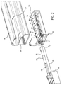
Figure 2 shows, in enlarged scale and in exploded view, some components of the covering device ofFigure 1 ; -
Figure 3 shows one of the components ofFigure 2 from a different point of view; and -
Figure 4 shows two different positions of components shown inFigure 2 . - In
Figure 1 , the reference number 1 indicates a covering device arranged in a trunk 4 (partially shown) of a motor vehicle and comprising arigid panel 5, which is rotatable about ahorizontal hinge axis 6, orthogonal to a longitudinal axis 7 defining the direction of travel of the motor vehicle. Thepanel 5 has anupper surface 8 supporting the luggage or other objects, so that the device 1 defines a loading floor. During normal driving conditions of the motor vehicle, thepanel 5 is arranged in a reference lowered position, where it is substantially horizontal and has alower surface 9 that covers abottom 10 of the trunk floor 4. This latter may house a spare wheel and/or service tools and/or may define an additional support surface for small objects and/or luggage. Thepanel 5 can be spaced from thefloor 10 and define, with this latter, an underlying space. - According to a variation not shown, the device 1 defines a parcel shelf of the trunk 4, instead of a loading floor.
- When it is rotated upward about the
axis 6 by the user, thepanel 5 comes to a reference raised position (in dotted line), where it is tilted so that the user can reach the objects arranged beneath thesurface 9. - To allow the rotation of the
panel 5 between the two reference positions, the device 1 comprises ahinge 12 coupling afront end portion 13 of thepanel 5 to a support body orstructure 14 fixedly arranged in the trunk 4 (here and below, the terms "rear", "front", "front", "forward", "back", etc... are meant with respect to the travel direction of the motor vehicle along the axis 7). As shown inFigure 2 , thehinge 12 comprises at least onehinge pin 20, which extends along theaxis 6 and, in particular, is fixed with respect to thestructure 14; and acorresponding hinge seat 21, which is rotatably engaged by thepin 20 and, in particular, is fixed with respect to thepanel 5. An alternative dual solution could provide thepin 20 fixed with respect to thepanel 5 and theseat 21 fixed with respect to thestructure 14. - In particular, the
hinge 12 comprises two coaxial and mutually facingpins 20 and twocorresponding seats 21. Preferably, the device 1 comprises a support profiledelement 24, which is elongated along theaxis 6, has aretention seat 25 engaged in a manner not shown by the front edge of theportion 13, and axially ends with twoopposing portions 26, respectively supporting theseats 21 in fixed positions, as described hereinafter in more detail. - According to the present invention, the device 1 comprises a retention and angular positioning system, which is indicated by the
reference number 30, is associated to thehinge 12, exerts an elastic force to hold thepanel 5 in at least one of the two reference positions, and allows thepanel 5 to rotate when the user exerts on the panel 5 a rotational torque greater than a given threshold. - Preferably, the
system 30 comprises at least onespring 31 to hold thepanel 5 in the lowered position, and at least onespring 32 to hold the panel in the raised position. In particular, thesprings axis 6. Thesprings seat 21 and, in particular, are fixedly arranged with respect to thepanel 5. - Advantageously, the
springs shaped casing 33 fixed to theelement 24 in a known way, not described in more detail. Thecasing 33 and thesprings portion 26. - A positioning system not shown is conveniently provided to hold the
springs pin 20, and/or to hold thesprings casing 33. - Moreover, a wall belonging to the
casing 33 or to theportion 26 defines a shoulder which rotates all thesprings element 24 and thepanel 5, while thepin 20 remains fixed. - In the shown example, the
springs system 30, and therefore the threshold torque that the user must exceed to rotate thepanel 5 in each of the two reference positions, may be adjusted by changing the number of thesprings 31 and/or 32 (and consequently the length of the casing 33). For example, thesystem 30 includes twosprings 31 and threesprings 32. - As shown in
Figure 3 , for each of the angular positions in which thepanel 5 must be held, thesystem 30 includes acorresponding portion springs 31 are fitted around theportion 35, while thesprings 32 are fitted around theportion 36. - The
portions portions circular areas 37, which extend as a mutual prolongation, and by respectiveflat areas 38. Theflat areas 38 are mutually offset about theaxis 6 by an angle equal to the one comprised between the two reference positions. - As shown in
Figure 4 , thesprings respective portions 40 having an inner profile, which is coupled to theportion portion circular area 41, coupled to thecircular area 37, and aflat area 42. When theflat area 42 is coupled to theflat area 38, theportion 40 exerts an elastic pressure on theflat area 38, resulting in a resistant torque which blocks the rotation of thepanel 5. When theflat area 42 is coupled to thecircular area 37, theportion 40 is more spread apart with respect to the rest configuration and theflat area 42 slides by friction on thecircular area 37 without touching theflat area 38. In this configuration, there is a simple friction between a flat area (42) and a circular area (37) at a tangent point, so that the resistant torque exerted by thesystem 30 is smaller than the rest configuration and is not sufficient to angularly lock thepanel 5.Figure 4 shows all of thesprings - As shown in
Figures 3 and 4 , thesprings end portions 45 that are mutually coupled and are joined to theportion 40 by means ofrespective arms 46, which are substantially radial and mutually facing. These types of springs exert an elastic force strong enough to support the weight of thepanel 5 when this latter is in the raised position. - In use, when the user wants to lift the
panel 5, he has to apply a rotational torque sufficient to overcome the resistance threshold of theflat areas 42 of thesprings 31 on theflat area 38 of theportion 35. Upon reaching the raised position, theflat areas 42 of thesprings 32 snappingly engage theflat area 38 of theportion 36, thus determining the angular locking of thepanel 5. - The reverse rotation is the same, i.e. the
flat areas 42 of thesprings 32 are uncoupled from theflat area 38 of theportion 36 by exceeding the threshold torque; then, at the end of the downward rotation, theflat areas 42 of thesprings 31 snappingly engage theflat area 38 of theportion 35. - From the aforesaid, it is clear how the
system 30 is relatively simple and compact, since it is integrated in thehinge 12. In fact, thesystem 30 is made up of components that define the pin 20 (i.e. theportions 35 and 36) and of components that define the seat 21 (i.e. thesprings 31 and 32). - Moreover, the
panel 5 is automatically locked in the raised and in the lowered positions when these are reached, with no manual intervention of the user to activate or deactivate a dedicated coupling system. In this way, for example, the user can lift thepanel 5 with a single hand, without having to intervene with the other hand to lock thepanel 5 in the raised position. - Other advantages have been described above, or are obvious to a person skilled in the art based on the aforesaid construction features.
- Finally, it is clear that the device 1 here described and shown can be modified and varied without departing from the protective scope of the present invention, as defined in the appended claims.
- In particular, the shape and/or the number and/or the relative position of the
springs
Claims (11)
- A covering device (1) for a trunk (4) of a motor vehicle; the covering device comprising:- a panel (5) comprising a front portion (13);- a support structure (14);- a hinge (12) coupling said front portion (13) to said support structure (14) and allowing said panel (5) to rotate about a horizontal hinge axis (6) between a lowered position, where said panel (5) is substantially horizontal, and a raised position, where said panel (5) is tilted upward;- retention means (30) to hold said panel (5) in at least one of the lowered and raised positions;characterized in that said retention means (30) are associated to said hinge (12) and comprise at least one spring (31,32), which exerts an elastic force to hold said panel (5) in said at least one of the lowered and raised positions, and allows said panel (5) to rotate when a rotational torque greater than a given threshold is exerted on said panel (5).
- A device according to claim 1, characterized in that said hinge (12) comprises at least one hinge pin (20) and at least one hinge seat (21) rotatably engaged by said hinge pin (20) about said hinge axis (6); said spring (31,32) defining at least part of said hinge seat (22).
- A device according to claim 2, characterized in that said retention means (30) also comprise at least one shaped portion (35, 36) forming part of said hinge pin (20) and having an area (38) with a cross-section other than circular; said spring comprising a retention portion (40) having, in a rest configuration, an inner profile with a shape complementary to the one of said area (38).
- A device according to claim 3, characterized in that said shaped portion has a cross-section defined by a first circular area (37) and by a first flat area (38).
- A device according to claim 3 or 4, characterized in that the inner profile of said retention portion (40) is U-shaped.
- A device according to claims 4 and 5, characterized in that the inner profile of said retention portion (40) comprises a second circular area (41) coupled to said first circular area (37) and a second flat area (42), which exerts said elastic retention force when it is coupled to said first flat area (38).
- A device according to any one of claims 2 to 6, characterized in that said spring is defined by a leaf spring.
- A device according to claim 7, characterized in that said flat spring ends with two portions (45) hooked together to close the leaf spring in a loop.
- A device according to any one of the preceding claims, characterized in that said retention means (30) comprise at least one first spring (31) to hold said panel in the lowered position, and at least one second spring (32) to hold said panel in the raised position.
- A device according to claim 9, characterized in that said first and second spring (31,32) are aligned and consecutive along said hinge axis (6).
- A device according to any one of the preceding claims, characterized in that said retention means (30) comprise a plurality of identical springs to hold said panel (5) in said at least one of the lowered and raised positions.
Priority Applications (1)
| Application Number | Priority Date | Filing Date | Title |
|---|---|---|---|
| EP16425046.6A EP3249142B1 (en) | 2016-05-24 | 2016-05-24 | Covering device for a trunk of a motor vehicle |
Applications Claiming Priority (1)
| Application Number | Priority Date | Filing Date | Title |
|---|---|---|---|
| EP16425046.6A EP3249142B1 (en) | 2016-05-24 | 2016-05-24 | Covering device for a trunk of a motor vehicle |
Publications (2)
| Publication Number | Publication Date |
|---|---|
| EP3249142A1 true EP3249142A1 (en) | 2017-11-29 |
| EP3249142B1 EP3249142B1 (en) | 2021-11-17 |
Family
ID=56497698
Family Applications (1)
| Application Number | Title | Priority Date | Filing Date |
|---|---|---|---|
| EP16425046.6A Active EP3249142B1 (en) | 2016-05-24 | 2016-05-24 | Covering device for a trunk of a motor vehicle |
Country Status (1)
| Country | Link |
|---|---|
| EP (1) | EP3249142B1 (en) |
Citations (2)
| Publication number | Priority date | Publication date | Assignee | Title |
|---|---|---|---|---|
| GB2412097A (en) * | 2004-03-08 | 2005-09-21 | Nifco Inc | Mechanism for a glove box lid |
| FR2883903A1 (en) * | 2005-03-30 | 2006-10-06 | Faurecia Automotive Ind Snc | Self-locking hinge for e.g. luggage covering shelf, of motor vehicle, has pin with cylindrical parts separated by parts with squared section that is blocked in respective squared section housing and cylindrical housing of isolated part |
Family Cites Families (1)
| Publication number | Priority date | Publication date | Assignee | Title |
|---|---|---|---|---|
| JP6175130B2 (en) * | 2013-04-09 | 2017-08-02 | 株式会社パイオラックス | Switchgear |
-
2016
- 2016-05-24 EP EP16425046.6A patent/EP3249142B1/en active Active
Patent Citations (2)
| Publication number | Priority date | Publication date | Assignee | Title |
|---|---|---|---|---|
| GB2412097A (en) * | 2004-03-08 | 2005-09-21 | Nifco Inc | Mechanism for a glove box lid |
| FR2883903A1 (en) * | 2005-03-30 | 2006-10-06 | Faurecia Automotive Ind Snc | Self-locking hinge for e.g. luggage covering shelf, of motor vehicle, has pin with cylindrical parts separated by parts with squared section that is blocked in respective squared section housing and cylindrical housing of isolated part |
Also Published As
| Publication number | Publication date |
|---|---|
| EP3249142B1 (en) | 2021-11-17 |
Similar Documents
| Publication | Publication Date | Title |
|---|---|---|
| US9315128B2 (en) | Vehicle seat and commercial vehicle with at least one vehicle seat | |
| US9555725B2 (en) | Adjustable vehicle seat | |
| CN104066617B (en) | Accessories for vehicle seats and vehicle seats | |
| EP2210768B1 (en) | Child vehicle seat | |
| CN108349438B (en) | Elbow rest with hinged armrests including improved unlocking mechanism | |
| CN106794788B (en) | Handrail | |
| KR101134875B1 (en) | Cup-holder Tray of rear-seat armrest for automobile | |
| US20160347209A1 (en) | Vehicle seat, in particular motor vehicle seat | |
| US20110127818A1 (en) | Seat assembly having dual actuated locking mechanism | |
| US20160039316A1 (en) | Easy-entry system for a vehicle seat, and vehicle seat | |
| CA2477619C (en) | Child car seat, swivelling between a forward facing position and a door facing position, with automatic return to forward facing position | |
| CN108349412A (en) | Seat | |
| US20200001742A1 (en) | Automotive vehicle seat | |
| US20260091739A1 (en) | System For Transporting Child Stroller | |
| US20120153696A1 (en) | Set of Slides for Vehicle Seats and Vehicle Seat Including Such a Set of Slides | |
| EP3249142B1 (en) | Covering device for a trunk of a motor vehicle | |
| EP3450386B1 (en) | Forklift | |
| JP6133742B2 (en) | Control lever structure and vehicle seat | |
| US9586503B1 (en) | Vehicle seat and torsion bar | |
| EP3390146B1 (en) | Multi-position locking device of a backrest of a rear seat of an automotive vehicle | |
| US10315540B2 (en) | Inertia stop link for stadium style seat cushion stowed positioning | |
| RU2667226C1 (en) | Door locking device | |
| US20130187423A1 (en) | Adjustment device for adjusting a motor vehicle seat, motor vehicle seat, motor vehicle and method for adjusting a motor vehicle seat | |
| EP1400395B1 (en) | Seat mounting devices | |
| CN110785324A (en) | System for actuating a motor vehicle trunk lid cross member into a locked position |
Legal Events
| Date | Code | Title | Description |
|---|---|---|---|
| PUAI | Public reference made under article 153(3) epc to a published international application that has entered the european phase |
Free format text: ORIGINAL CODE: 0009012 |
|
| STAA | Information on the status of an ep patent application or granted ep patent |
Free format text: STATUS: THE APPLICATION HAS BEEN PUBLISHED |
|
| AK | Designated contracting states |
Kind code of ref document: A1 Designated state(s): AL AT BE BG CH CY CZ DE DK EE ES FI FR GB GR HR HU IE IS IT LI LT LU LV MC MK MT NL NO PL PT RO RS SE SI SK SM TR |
|
| AX | Request for extension of the european patent |
Extension state: BA ME |
|
| STAA | Information on the status of an ep patent application or granted ep patent |
Free format text: STATUS: REQUEST FOR EXAMINATION WAS MADE |
|
| 17P | Request for examination filed |
Effective date: 20180528 |
|
| RBV | Designated contracting states (corrected) |
Designated state(s): AL AT BE BG CH CY CZ DE DK EE ES FI FR GB GR HR HU IE IS IT LI LT LU LV MC MK MT NL NO PL PT RO RS SE SI SK SM TR |
|
| STAA | Information on the status of an ep patent application or granted ep patent |
Free format text: STATUS: EXAMINATION IS IN PROGRESS |
|
| 17Q | First examination report despatched |
Effective date: 20181008 |
|
| GRAP | Despatch of communication of intention to grant a patent |
Free format text: ORIGINAL CODE: EPIDOSNIGR1 |
|
| STAA | Information on the status of an ep patent application or granted ep patent |
Free format text: STATUS: GRANT OF PATENT IS INTENDED |
|
| INTG | Intention to grant announced |
Effective date: 20210611 |
|
| GRAS | Grant fee paid |
Free format text: ORIGINAL CODE: EPIDOSNIGR3 |
|
| GRAA | (expected) grant |
Free format text: ORIGINAL CODE: 0009210 |
|
| STAA | Information on the status of an ep patent application or granted ep patent |
Free format text: STATUS: THE PATENT HAS BEEN GRANTED |
|
| AK | Designated contracting states |
Kind code of ref document: B1 Designated state(s): AL AT BE BG CH CY CZ DE DK EE ES FI FR GB GR HR HU IE IS IT LI LT LU LV MC MK MT NL NO PL PT RO RS SE SI SK SM TR |
|
| REG | Reference to a national code |
Ref country code: GB Ref legal event code: FG4D |
|
| REG | Reference to a national code |
Ref country code: DE Ref legal event code: R096 Ref document number: 602016066269 Country of ref document: DE |
|
| REG | Reference to a national code |
Ref country code: IE Ref legal event code: FG4D |
|
| REG | Reference to a national code |
Ref country code: AT Ref legal event code: REF Ref document number: 1448186 Country of ref document: AT Kind code of ref document: T Effective date: 20211215 |
|
| REG | Reference to a national code |
Ref country code: LT Ref legal event code: MG9D |
|
| REG | Reference to a national code |
Ref country code: NL Ref legal event code: MP Effective date: 20211117 |
|
| REG | Reference to a national code |
Ref country code: AT Ref legal event code: MK05 Ref document number: 1448186 Country of ref document: AT Kind code of ref document: T Effective date: 20211117 |
|
| PG25 | Lapsed in a contracting state [announced via postgrant information from national office to epo] |
Ref country code: RS Free format text: LAPSE BECAUSE OF FAILURE TO SUBMIT A TRANSLATION OF THE DESCRIPTION OR TO PAY THE FEE WITHIN THE PRESCRIBED TIME-LIMIT Effective date: 20211117 Ref country code: LT Free format text: LAPSE BECAUSE OF FAILURE TO SUBMIT A TRANSLATION OF THE DESCRIPTION OR TO PAY THE FEE WITHIN THE PRESCRIBED TIME-LIMIT Effective date: 20211117 Ref country code: FI Free format text: LAPSE BECAUSE OF FAILURE TO SUBMIT A TRANSLATION OF THE DESCRIPTION OR TO PAY THE FEE WITHIN THE PRESCRIBED TIME-LIMIT Effective date: 20211117 Ref country code: BG Free format text: LAPSE BECAUSE OF FAILURE TO SUBMIT A TRANSLATION OF THE DESCRIPTION OR TO PAY THE FEE WITHIN THE PRESCRIBED TIME-LIMIT Effective date: 20220217 Ref country code: AT Free format text: LAPSE BECAUSE OF FAILURE TO SUBMIT A TRANSLATION OF THE DESCRIPTION OR TO PAY THE FEE WITHIN THE PRESCRIBED TIME-LIMIT Effective date: 20211117 |
|
| PG25 | Lapsed in a contracting state [announced via postgrant information from national office to epo] |
Ref country code: IS Free format text: LAPSE BECAUSE OF FAILURE TO SUBMIT A TRANSLATION OF THE DESCRIPTION OR TO PAY THE FEE WITHIN THE PRESCRIBED TIME-LIMIT Effective date: 20220317 Ref country code: SE Free format text: LAPSE BECAUSE OF FAILURE TO SUBMIT A TRANSLATION OF THE DESCRIPTION OR TO PAY THE FEE WITHIN THE PRESCRIBED TIME-LIMIT Effective date: 20211117 Ref country code: PT Free format text: LAPSE BECAUSE OF FAILURE TO SUBMIT A TRANSLATION OF THE DESCRIPTION OR TO PAY THE FEE WITHIN THE PRESCRIBED TIME-LIMIT Effective date: 20220317 Ref country code: PL Free format text: LAPSE BECAUSE OF FAILURE TO SUBMIT A TRANSLATION OF THE DESCRIPTION OR TO PAY THE FEE WITHIN THE PRESCRIBED TIME-LIMIT Effective date: 20211117 Ref country code: NO Free format text: LAPSE BECAUSE OF FAILURE TO SUBMIT A TRANSLATION OF THE DESCRIPTION OR TO PAY THE FEE WITHIN THE PRESCRIBED TIME-LIMIT Effective date: 20220217 Ref country code: NL Free format text: LAPSE BECAUSE OF FAILURE TO SUBMIT A TRANSLATION OF THE DESCRIPTION OR TO PAY THE FEE WITHIN THE PRESCRIBED TIME-LIMIT Effective date: 20211117 Ref country code: LV Free format text: LAPSE BECAUSE OF FAILURE TO SUBMIT A TRANSLATION OF THE DESCRIPTION OR TO PAY THE FEE WITHIN THE PRESCRIBED TIME-LIMIT Effective date: 20211117 Ref country code: HR Free format text: LAPSE BECAUSE OF FAILURE TO SUBMIT A TRANSLATION OF THE DESCRIPTION OR TO PAY THE FEE WITHIN THE PRESCRIBED TIME-LIMIT Effective date: 20211117 Ref country code: GR Free format text: LAPSE BECAUSE OF FAILURE TO SUBMIT A TRANSLATION OF THE DESCRIPTION OR TO PAY THE FEE WITHIN THE PRESCRIBED TIME-LIMIT Effective date: 20220218 Ref country code: ES Free format text: LAPSE BECAUSE OF FAILURE TO SUBMIT A TRANSLATION OF THE DESCRIPTION OR TO PAY THE FEE WITHIN THE PRESCRIBED TIME-LIMIT Effective date: 20211117 |
|
| PG25 | Lapsed in a contracting state [announced via postgrant information from national office to epo] |
Ref country code: SM Free format text: LAPSE BECAUSE OF FAILURE TO SUBMIT A TRANSLATION OF THE DESCRIPTION OR TO PAY THE FEE WITHIN THE PRESCRIBED TIME-LIMIT Effective date: 20211117 Ref country code: SK Free format text: LAPSE BECAUSE OF FAILURE TO SUBMIT A TRANSLATION OF THE DESCRIPTION OR TO PAY THE FEE WITHIN THE PRESCRIBED TIME-LIMIT Effective date: 20211117 Ref country code: RO Free format text: LAPSE BECAUSE OF FAILURE TO SUBMIT A TRANSLATION OF THE DESCRIPTION OR TO PAY THE FEE WITHIN THE PRESCRIBED TIME-LIMIT Effective date: 20211117 Ref country code: EE Free format text: LAPSE BECAUSE OF FAILURE TO SUBMIT A TRANSLATION OF THE DESCRIPTION OR TO PAY THE FEE WITHIN THE PRESCRIBED TIME-LIMIT Effective date: 20211117 Ref country code: DK Free format text: LAPSE BECAUSE OF FAILURE TO SUBMIT A TRANSLATION OF THE DESCRIPTION OR TO PAY THE FEE WITHIN THE PRESCRIBED TIME-LIMIT Effective date: 20211117 Ref country code: CZ Free format text: LAPSE BECAUSE OF FAILURE TO SUBMIT A TRANSLATION OF THE DESCRIPTION OR TO PAY THE FEE WITHIN THE PRESCRIBED TIME-LIMIT Effective date: 20211117 |
|
| REG | Reference to a national code |
Ref country code: DE Ref legal event code: R097 Ref document number: 602016066269 Country of ref document: DE |
|
| PLBE | No opposition filed within time limit |
Free format text: ORIGINAL CODE: 0009261 |
|
| STAA | Information on the status of an ep patent application or granted ep patent |
Free format text: STATUS: NO OPPOSITION FILED WITHIN TIME LIMIT |
|
| 26N | No opposition filed |
Effective date: 20220818 |
|
| PG25 | Lapsed in a contracting state [announced via postgrant information from national office to epo] |
Ref country code: AL Free format text: LAPSE BECAUSE OF FAILURE TO SUBMIT A TRANSLATION OF THE DESCRIPTION OR TO PAY THE FEE WITHIN THE PRESCRIBED TIME-LIMIT Effective date: 20211117 |
|
| PG25 | Lapsed in a contracting state [announced via postgrant information from national office to epo] |
Ref country code: SI Free format text: LAPSE BECAUSE OF FAILURE TO SUBMIT A TRANSLATION OF THE DESCRIPTION OR TO PAY THE FEE WITHIN THE PRESCRIBED TIME-LIMIT Effective date: 20211117 |
|
| REG | Reference to a national code |
Ref country code: CH Ref legal event code: PL |
|
| REG | Reference to a national code |
Ref country code: BE Ref legal event code: MM Effective date: 20220531 |
|
| GBPC | Gb: european patent ceased through non-payment of renewal fee |
Effective date: 20220524 |
|
| PG25 | Lapsed in a contracting state [announced via postgrant information from national office to epo] |
Ref country code: MC Free format text: LAPSE BECAUSE OF FAILURE TO SUBMIT A TRANSLATION OF THE DESCRIPTION OR TO PAY THE FEE WITHIN THE PRESCRIBED TIME-LIMIT Effective date: 20211117 Ref country code: LU Free format text: LAPSE BECAUSE OF NON-PAYMENT OF DUE FEES Effective date: 20220524 Ref country code: LI Free format text: LAPSE BECAUSE OF NON-PAYMENT OF DUE FEES Effective date: 20220531 Ref country code: CH Free format text: LAPSE BECAUSE OF NON-PAYMENT OF DUE FEES Effective date: 20220531 |
|
| PG25 | Lapsed in a contracting state [announced via postgrant information from national office to epo] |
Ref country code: IE Free format text: LAPSE BECAUSE OF NON-PAYMENT OF DUE FEES Effective date: 20220524 |
|
| PG25 | Lapsed in a contracting state [announced via postgrant information from national office to epo] |
Ref country code: GB Free format text: LAPSE BECAUSE OF NON-PAYMENT OF DUE FEES Effective date: 20220524 Ref country code: BE Free format text: LAPSE BECAUSE OF NON-PAYMENT OF DUE FEES Effective date: 20220531 |
|
| PG25 | Lapsed in a contracting state [announced via postgrant information from national office to epo] |
Ref country code: HU Free format text: LAPSE BECAUSE OF FAILURE TO SUBMIT A TRANSLATION OF THE DESCRIPTION OR TO PAY THE FEE WITHIN THE PRESCRIBED TIME-LIMIT; INVALID AB INITIO Effective date: 20160524 |
|
| PG25 | Lapsed in a contracting state [announced via postgrant information from national office to epo] |
Ref country code: MK Free format text: LAPSE BECAUSE OF FAILURE TO SUBMIT A TRANSLATION OF THE DESCRIPTION OR TO PAY THE FEE WITHIN THE PRESCRIBED TIME-LIMIT Effective date: 20211117 Ref country code: CY Free format text: LAPSE BECAUSE OF FAILURE TO SUBMIT A TRANSLATION OF THE DESCRIPTION OR TO PAY THE FEE WITHIN THE PRESCRIBED TIME-LIMIT Effective date: 20211117 |
|
| PG25 | Lapsed in a contracting state [announced via postgrant information from national office to epo] |
Ref country code: TR Free format text: LAPSE BECAUSE OF FAILURE TO SUBMIT A TRANSLATION OF THE DESCRIPTION OR TO PAY THE FEE WITHIN THE PRESCRIBED TIME-LIMIT Effective date: 20211117 |
|
| PG25 | Lapsed in a contracting state [announced via postgrant information from national office to epo] |
Ref country code: MT Free format text: LAPSE BECAUSE OF FAILURE TO SUBMIT A TRANSLATION OF THE DESCRIPTION OR TO PAY THE FEE WITHIN THE PRESCRIBED TIME-LIMIT Effective date: 20211117 |
|
| PGFP | Annual fee paid to national office [announced via postgrant information from national office to epo] |
Ref country code: DE Payment date: 20250430 Year of fee payment: 10 |
|
| PGFP | Annual fee paid to national office [announced via postgrant information from national office to epo] |
Ref country code: IT Payment date: 20250520 Year of fee payment: 10 |
|
| PGFP | Annual fee paid to national office [announced via postgrant information from national office to epo] |
Ref country code: FR Payment date: 20250428 Year of fee payment: 10 |
|
| REG | Reference to a national code |
Ref country code: DE Ref legal event code: R081 Ref document number: 602016066269 Country of ref document: DE Owner name: STELLANTIS EUROPE S.P.A., IT Free format text: FORMER OWNER: FCA ITALY S.P.A., TORINO, IT |