EP3248840B1 - Automotive lighting appliance - Google Patents
Automotive lighting appliance Download PDFInfo
- Publication number
- EP3248840B1 EP3248840B1 EP17172969.2A EP17172969A EP3248840B1 EP 3248840 B1 EP3248840 B1 EP 3248840B1 EP 17172969 A EP17172969 A EP 17172969A EP 3248840 B1 EP3248840 B1 EP 3248840B1
- Authority
- EP
- European Patent Office
- Prior art keywords
- light
- guide plate
- sidewall
- plate
- lighting appliance
- Prior art date
- Legal status (The legal status is an assumption and is not a legal conclusion. Google has not performed a legal analysis and makes no representation as to the accuracy of the status listed.)
- Active
Links
Images



Classifications
-
- B—PERFORMING OPERATIONS; TRANSPORTING
- B60—VEHICLES IN GENERAL
- B60Q—ARRANGEMENT OF SIGNALLING OR LIGHTING DEVICES, THE MOUNTING OR SUPPORTING THEREOF OR CIRCUITS THEREFOR, FOR VEHICLES IN GENERAL
- B60Q1/00—Arrangement of optical signalling or lighting devices, the mounting or supporting thereof or circuits therefor
- B60Q1/26—Arrangement of optical signalling or lighting devices, the mounting or supporting thereof or circuits therefor the devices being primarily intended to indicate the vehicle, or parts thereof, or to give signals, to other traffic
- B60Q1/2607—Arrangement of optical signalling or lighting devices, the mounting or supporting thereof or circuits therefor the devices being primarily intended to indicate the vehicle, or parts thereof, or to give signals, to other traffic comprising at least two indicating lamps
-
- B—PERFORMING OPERATIONS; TRANSPORTING
- B60—VEHICLES IN GENERAL
- B60Q—ARRANGEMENT OF SIGNALLING OR LIGHTING DEVICES, THE MOUNTING OR SUPPORTING THEREOF OR CIRCUITS THEREFOR, FOR VEHICLES IN GENERAL
- B60Q1/00—Arrangement of optical signalling or lighting devices, the mounting or supporting thereof or circuits therefor
- B60Q1/26—Arrangement of optical signalling or lighting devices, the mounting or supporting thereof or circuits therefor the devices being primarily intended to indicate the vehicle, or parts thereof, or to give signals, to other traffic
- B60Q1/2696—Mounting of devices using LEDs
-
- F—MECHANICAL ENGINEERING; LIGHTING; HEATING; WEAPONS; BLASTING
- F21—LIGHTING
- F21S—NON-PORTABLE LIGHTING DEVICES; SYSTEMS THEREOF; VEHICLE LIGHTING DEVICES SPECIALLY ADAPTED FOR VEHICLE EXTERIORS
- F21S43/00—Signalling devices specially adapted for vehicle exteriors, e.g. brake lamps, direction indicator lights or reversing lights
- F21S43/10—Signalling devices specially adapted for vehicle exteriors, e.g. brake lamps, direction indicator lights or reversing lights characterised by the light source
- F21S43/13—Signalling devices specially adapted for vehicle exteriors, e.g. brake lamps, direction indicator lights or reversing lights characterised by the light source characterised by the type of light source
- F21S43/14—Light emitting diodes [LED]
-
- F—MECHANICAL ENGINEERING; LIGHTING; HEATING; WEAPONS; BLASTING
- F21—LIGHTING
- F21S—NON-PORTABLE LIGHTING DEVICES; SYSTEMS THEREOF; VEHICLE LIGHTING DEVICES SPECIALLY ADAPTED FOR VEHICLE EXTERIORS
- F21S43/00—Signalling devices specially adapted for vehicle exteriors, e.g. brake lamps, direction indicator lights or reversing lights
- F21S43/20—Signalling devices specially adapted for vehicle exteriors, e.g. brake lamps, direction indicator lights or reversing lights characterised by refractors, transparent cover plates, light guides or filters
- F21S43/235—Light guides
- F21S43/236—Light guides characterised by the shape of the light guide
- F21S43/239—Light guides characterised by the shape of the light guide plate-shaped
-
- F—MECHANICAL ENGINEERING; LIGHTING; HEATING; WEAPONS; BLASTING
- F21—LIGHTING
- F21S—NON-PORTABLE LIGHTING DEVICES; SYSTEMS THEREOF; VEHICLE LIGHTING DEVICES SPECIALLY ADAPTED FOR VEHICLE EXTERIORS
- F21S43/00—Signalling devices specially adapted for vehicle exteriors, e.g. brake lamps, direction indicator lights or reversing lights
- F21S43/20—Signalling devices specially adapted for vehicle exteriors, e.g. brake lamps, direction indicator lights or reversing lights characterised by refractors, transparent cover plates, light guides or filters
- F21S43/235—Light guides
- F21S43/242—Light guides characterised by the emission area
- F21S43/243—Light guides characterised by the emission area emitting light from one or more of its extremities
-
- F—MECHANICAL ENGINEERING; LIGHTING; HEATING; WEAPONS; BLASTING
- F21—LIGHTING
- F21S—NON-PORTABLE LIGHTING DEVICES; SYSTEMS THEREOF; VEHICLE LIGHTING DEVICES SPECIALLY ADAPTED FOR VEHICLE EXTERIORS
- F21S43/00—Signalling devices specially adapted for vehicle exteriors, e.g. brake lamps, direction indicator lights or reversing lights
- F21S43/20—Signalling devices specially adapted for vehicle exteriors, e.g. brake lamps, direction indicator lights or reversing lights characterised by refractors, transparent cover plates, light guides or filters
- F21S43/235—Light guides
- F21S43/249—Light guides with two or more light sources being coupled into the light guide
-
- G—PHYSICS
- G02—OPTICS
- G02B—OPTICAL ELEMENTS, SYSTEMS OR APPARATUS
- G02B6/00—Light guides; Structural details of arrangements comprising light guides and other optical elements, e.g. couplings
- G02B6/0001—Light guides; Structural details of arrangements comprising light guides and other optical elements, e.g. couplings specially adapted for lighting devices or systems
- G02B6/0011—Light guides; Structural details of arrangements comprising light guides and other optical elements, e.g. couplings specially adapted for lighting devices or systems the light guides being planar or of plate-like form
- G02B6/0013—Means for improving the coupling-in of light from the light source into the light guide
- G02B6/0015—Means for improving the coupling-in of light from the light source into the light guide provided on the surface of the light guide or in the bulk of it
- G02B6/0018—Redirecting means on the surface of the light guide
-
- G—PHYSICS
- G02—OPTICS
- G02B—OPTICAL ELEMENTS, SYSTEMS OR APPARATUS
- G02B6/00—Light guides; Structural details of arrangements comprising light guides and other optical elements, e.g. couplings
- G02B6/0001—Light guides; Structural details of arrangements comprising light guides and other optical elements, e.g. couplings specially adapted for lighting devices or systems
- G02B6/0011—Light guides; Structural details of arrangements comprising light guides and other optical elements, e.g. couplings specially adapted for lighting devices or systems the light guides being planar or of plate-like form
- G02B6/0075—Arrangements of multiple light guides
- G02B6/0078—Side-by-side arrangements, e.g. for large area displays
Definitions
- the present invention relates to an automotive lighting appliance.
- the present invention relates to a headlight or taillight for cars and the like, i.e. a lighting appliance adapted to be incorporated into a vehicle with the function of lighting the surrounding area of the vehicle, or to signal the presence, the position and/or the movement direction of the vehicle.
- a lighting appliance adapted to be incorporated into a vehicle with the function of lighting the surrounding area of the vehicle, or to signal the presence, the position and/or the movement direction of the vehicle.
- the taillights for cars and motor vehicles in general usually comprise: a substantially basin-shaped rear casing, which is structured so as to be stably recessed into in a specially designed seat in the rear part of the vehicle body; a front half-shell, which is arranged to close the opening of the casing so as to surface from the vehicle body, and is usually provided with a plurality of transparent or semi-transparent portions, generally having different colours to one another; and a series of lighting assemblies which are located inside the casing each immediately beneath a respective transparent or semi-transparent portion of the front half-shell, so as to be able to backlight the same transparent or semi-transparent portion of the half-shell.
- each lighting assembly is univocally related to a specific light signal, and is thus structured so as to emit a light beam that, once come out from the automotive light through the front half-shell, meets the homologation specifications provided for said light signal.
- the front half-shell is provided with at least one transparent or semi-transparent portion which is narrow and elongated in shape, i.e. substantially ribbon-like, is horizontally arranged when the automotive light is mounted on the vehicle, and is usually associated to the position light signal or the blinking direction/turn light signal.
- each of the transparent or semi-transparent ribbon-like portions is backlighted by a lighting assembly which essentially comprises: a large light-guide plate made of photoconductive material, which is placed inside the rear casing with the front sidewall adjacent to the transparent or semi-transparent ribbon-like portion of the front half-shell, substantially for the whole length of the same transparent or semi-transparent ribbon-like portion, and with the rear sidewall facing the bottom of the rear casing; and a row of LED diodes which are placed on the bottom of the rear casing, in abutting against the rear sidewall of the light-guide plate, and are oriented so as to direct the light produced directly into the body of the light-guide plate. Light that then travels inside the body of the light-guide plate, coming out of the light-guide plate through the front sidewall of the plate.
- the light-guide plate usually has a rather large width, making it extremely difficult to reduce the depth of the automotive light.
- the light produced by this small group of LED diodes reaches the front sidewall of the light-guide plate following an optical path that has a length substantially equal to that of the optical path followed by the light emitted by the LED diodes placed in abutment against the rest of the rear sidewall of the light-guide plate.
- this small end segment of the front sidewall of the light-guide plate has a brightness visibly greater than the rest of the front sidewall.
- the light coming out of the light-guide plate does not have a uniform intensity throughout the whole length of the front sidewall of the plate, and is therefore unable to evenly backlight the corresponding transparent or semi-transparent ribbon-like portion of the front half-shell, with all the problems that this entails.
- a light signal that excessively varies in its intensity along the front half-shell of the automotive light in fact, is considered aesthetically unattractive by the external observer and is obviously undesired by the automotive manufacturers.
- DE 10 2014 110225 A1 discloses an automotive lighting appliance comprising a light-guide plate made of photoconductive material and light emitting means which are located at or close to the sidewall of the light-guide plate, and are adapted to direct the light produced inside the light-guide plate so that said light travels inside the light-guide plate towards the front of the light-guide plate and is emitted from the light-guide plate.
- the light-guide plate is divided into at least a first and a second plate-like sector co-planar to each other, which are arranged mutually adjacent and contiguous, are made of photoconductive materials with refractive indices different from each other, and are stably joined to each other to form a single plate-like body/piece along a join line.
- Aim of the present invention is to eliminate the adverse effects due to the presence of LED diodes turned towards the lateral sidewall of the light-guide plate, without thereby reducing the intensity of the light emitted from the front sidewall of the light-guide plate parallel to the main optical axis of the automotive light.
- an automotive light as defined in claim 1 and preferably, though not necessarily, in any of the claims dependent thereon.
- number 1 denotes as a whole an automotive lighting appliance particularly suitable to be fixed/incorporated into a vehicle, preferably with the function of lighting the surrounding area of the vehicle, or to signal the presence, the position and/or the movement direction of the vehicle.
- the lighting appliance 1 is particularly suitable to be fixed to the front or rear part of the vehicle body of an car, van, truck, motorcycle or the like, so as to perform the function of automotive headlight or taillight.
- the lighting appliance 1 is preferably structured to be stably recessed into the rear part of the vehicle body of a car or similar motor vehicle, so as to perform the function of an automotive taillight.
- the lighting appliance 1 firstly comprises: a rigid and preferably made of plastic material, rear casing 2 which is roughly basin-shaped, and is preferably structured so as to be at least partially recessed into a seat specifically formed in the rear part of the vehicle body (not shown); a rigid and preferably made of plastic material, a front half-shell 3 which is arranged to close the opening 2a of rear casing 2, preferably so to simultaneously surface outside of the vehicle body, and is provided with one or more transparent or semi-transparent portions, optionally also coloured; and one or more electrically-powered lighting assemblies, each of which emits light on command and is arranged inside the rear casing 2 in a position so as to backlight a corresponding transparent or semi-transparent portion of the front half-shell 3, preferably separately and independently from the other lighting assemblies.
- the rear casing 2 could also be structured to be simply fixed in a cantilevered manner on the rear part of the vehicle body (not shown).
- the lighting appliance 1 is provided with a main optical axis X which is parallel to the longitudinal axis of the vehicle when the lighting appliance 1 is correctly positioned/fixed on the vehicle body, and one or more of said lighting assemblies is/are preferably structured so as to direct the light outside of the lighting appliance 1 with a predominant component parallel to the main optical axis X of the lighting appliance.
- the front half-shell 3 is preferably provided with at least one transparent or semi-transparent portion 4 having a narrow and elongated shape, i.e. substantially ribbon-like, which preferably extends substantially horizontally when the lighting appliance 1 is mounted on the vehicle.
- the lighting assembly designed to backlight the transparent or semi-transparent ribbon-like portion 4 of the lenticular half-shell 3, hereinafter referred to with the number 5, is instead placed inside the rear casing 2 immediately beneath the transparent or semi-transparent ribbon-like portion 4, so as to be directly facing the same transparent or semi-transparent ribbon-like portion 4 and is structured so as to direct the light produced towards the transparent or semi-transparent ribbon-like portion 4.
- the lighting assembly 5 is moreover structured to project/direct the light outside of the lighting appliance 1 through the transparent or semi-transparent ribbon-like portion 4 with a predominant component parallel to the main optical axis X of lighting appliance 1.
- the rear casing 2 is preferably made of opaque plastic material, preferably via an injection moulding process.
- the front half-shell 3, on the other hand, is preferably made of transparent or semi-transparent plastic material, such as transparent or semi-transparent polycarbonate or polymethylmethacrylate, also in this case preferably via an injection moulding process.
- the lighting assembly 5 in turn comprises: at least one photoconductive-material light-guide plate 6, which is preferably made of transparent plastic material, and is arranged inside the rear casing 2 with its front sidewall 7 substantially coplanar and directly facing the transparent or semi-transparent ribbon-like portion 4 of front half-shell 3, preferably substantially for the whole length of the transparent or semi-transparent ribbon-like portion 4, and with its rear sidewall 8 facing the bottom of rear casing 2; and an electrically-powered light emitting device 9, which is capable of emitting light on command, extends inside the rear casing 2 at or close to the rear sidewall 8 of light-guide plate 6, and is capable of directing the produced light directly inside the body of the light-guide plate 6 substantially throughout the entire length of rear sidewall 8.
- an electrically-powered light emitting device 9 which is capable of emitting light on command, extends inside the rear casing 2 at or close to the rear sidewall 8 of light-guide plate 6, and is capable of directing the produced light directly inside the body of the light-guide plate 6 substantially throughout the entire length of rear side
- the front sidewall 7 of light-guide plate 6 is preferably arranged locally adjacent/tangent to the transparent or semi-transparent ribbon-like portion 4 of front half-shell 3, preferably substantially throughout the whole length of the transparent or semi-transparent ribbon-like portion 4.
- the light-guide plate 6 also extends inside the rear casing 2 while remaining locally substantially perpendicular to the transparent or semi-transparent ribbon-like portion 4 of front half-shell 3.
- the lying plane of the light-guide plate 6 is moreover substantially parallel to the main optical axis X of the lighting-appliance 1.
- the light emitting device 9 on the other hand comprises: a first electrically-powered light source which is located at or close to a first segment 8a of the rear sidewall 8 of light-guide plate 6, and is adapted to direct the light produced directly inside the light-guide plate 6 substantially throughout the whole length of segment 8a; and a second electrically-powered light source which is located at or close to a second segment 8b of the rear sidewall 8 of light-guide plate 6 consecutive and complementary to the segment 8a, and is adapted to direct the light produced directly inside the light-guide plate 6 substantially throughout the whole length of segment 8b.
- the rear sidewall 8 of light-guide plate 6 is divided into at least a first 8a and a second 8b segment complementary to each other.
- the first light source is capable of lighting the segment 8a of the rear sidewall 8 of light-guide plate 6;
- the second light source is capable of lighting the segment 8b of the rear sidewall 8 of light-guide plate 6.
- the length of segment 8a of the rear sidewall 8 of light-guide plate 6 is moreover greater than the length of segment 8b.
- the light-guide plate 6 is provided with a first, preferably substantially rectilinear, sidewall 10 that connects/joins the front sidewall 7 of light-guide plate 6 to the segment 8b of rear sidewall 8.
- the first light source is capable of directing the light produced inside the light-guide plate 6 so that said light directly reaches the front sidewall 7 of light-guide plate 6.
- the second light source is capable of directing the light produced inside the light-guide plate 6 so that said light reaches the lateral sidewall 10 of light-guide plate 6 and is there reflected by total internal reflection towards the front sidewall 7 of light-guide plate 6.
- the light coming from the second light source reaches the lateral sidewall 10 of light-guide plate 6 with an incidence angle above the limit angle so as to be reflected by total internal reflection towards the front sidewall 7 of light-guide plate 6.
- the light-guide plate 6 is divided into at least two plate-like sectors 11 and 12 coplanar and complementary to each other and which are arranged mutually adjacent and contiguous, are made of photoconductive materials with refractive indices different to one another, and are stably joined to each other to form a sole / single plate-like body / piece.
- the two plate-like segments 11 and 12 are seamlessly joined to one another along a transversal join line/ band 13 which preferably takes up the whole thickness of the light-guide plate 6, and which roughly extends from the vertex 14 of the light-guide plate 6 delimited/identified by the front sidewall 7 and by the lateral sidewall 10 of the plate, up to an intermediate point of the rear sidewall 8 of light-guide plate 6 that preferably substantially coincides with the joining point between segment 8a and segment 8b of rear sidewall 8.
- a transversal join line/ band 13 which preferably takes up the whole thickness of the light-guide plate 6, and which roughly extends from the vertex 14 of the light-guide plate 6 delimited/identified by the front sidewall 7 and by the lateral sidewall 10 of the plate, up to an intermediate point of the rear sidewall 8 of light-guide plate 6 that preferably substantially coincides with the joining point between segment 8a and segment 8b of rear sidewall 8.
- the plate-like sector 11 is thus shaped so as to substantially form the whole front sidewall 7 of light-guide plate 6 and the segment 8a of the rear sidewall 8 of light-guide plate 6.
- the light-guide plate 6 is moreover substantially quadrilateral in shape, and the plate-like sector 11 is shaped so as to additionally form the second lateral sidewall 15 of light-guide plate 6 connecting/joining the segment 8a of lateral sidewall 8 with the front sidewall 7.
- the plate-like sector 12 is preferably substantially triangular in shape, and is designed so as to substantially form the whole lateral sidewall 10 of light-guide plate 6 and the segment 8b of the rear sidewall 8 of light-guide plate 6.
- the join line 13 between the plate-like sectors 11 and 12 therefore, extends along the light-guide plate 6 so as to be crossed by the light reflected by lateral sidewall 10 and directed towards the front sidewall 7 of light-guide plate 6.
- join line 13 between the plate-like sectors 11 and 12 is moreover arranged so as to reflect, for total internal reflection and away from the front sidewall 7 of light-guide plate 6, the light emitted by the second light source of light emitting device 9, and which is directed directly towards the front sidewall 7 of light-guide plate 6, while intersecting the join line 13 without firstly bouncing on the lateral sidewall 10 of light-guide plate 6.
- the join line 13 is capable of reflecting, away from the front sidewall 7 of light-guide plate 6, the light arriving directly from the second light source of light emitting device 9 and directed towards the front sidewall 7 of light-guide plate 6.
- plate-like sector 11 preferably has an extension greater than that of plate-like sector 12.
- the two plate-like sectors 11 and 12 are moreover made of plastic material, via a co-injection moulding process.
- the plate-like sector 11 is preferably made of polycarbonate (PC) which has a refractive index approximately equal to about 1,586; whereas the plate-like sector 12 is preferably made of polymethylmethacrylate (PMMA) which in turn has a refractive index equal to about 1.493.
- PC polycarbonate
- PMMA polymethylmethacrylate
- plate-like sector 11 preferably has a refractive index greater than the refractive index of plate-like sector 12.
- the variation of refractive index may also be obtained by using a same plastic material for both plate-like sectors 11 and 12, and altering the refractive index of one or both the plate-like sectors 11 and 12 with the addition of an additive.
- the transversal join line 13 is preferably substantially rectilinear and preferably extends along the body of light-guide plate 6 with an angle of inclination ⁇ with respect to the main optical axis X of lighting appliance 1 preferably greater than 60°.
- the transversal join line 13 preferably extends towards the joining point between segment 8a and segment 8b of the rear sidewall 8 of light-guide plate 6 while remaining locally substantially perpendicular to the main optical axis X of lighting appliance 1.
- the transversal join line 13 moreover departs from vertex 14 of light-guide plate 6, at the joint between the front sidewall 7 and the lateral sidewall 10 of light-guide plate 6.
- the lateral sidewall 10 of light-guide plate 6 preferably has a stepped profile.
- the lateral sidewall 15 of light-guide plate 6, in turn, is preferably substantially rectilinear, and preferably also locally substantially parallel to the main optical axis X of lighting appliance 1.
- the first light source of light emitting device 9 in turn preferably comprises a first series of LED diodes 18 (acronym of Light Emitting Diode) or other light sources preferably of punctiform type, which are aligned one next to the other to form a row, are placed inside the rear casing 2 adjacent to the segment 8a of the rear sidewall 8 of light-guide plate 6, and are oriented so as to direct the light produced directly inside the plate-like sector 11.
- LED diodes 18 ascronym of Light Emitting Diode
- other light sources preferably of punctiform type
- the row of LED diodes 18 moreover extends skimmed over one of the two faces of plate-like sector 11, aside and parallel to the segment 8a of the rear sidewall 8 of light-guide plate 6; and each LED diode 18 is preferably oriented so as to direct the light produced directly inside the plate-like sector 11 towards the rear sidewall 8 of light-guide plate 6. Light that then reaches the rear sidewall 8 of light-guide plate 6 with an incidence angle above the limit angle so as to be reflected by total internal reflection directly towards the front sidewall 7 of light-guide plate 6.
- the second light source of light emitting device 9 preferably comprises a second series of LED diodes 19 (acronym of Light Emitting Diode) or other light sources preferably of punctiform type, which are aligned one next to the other to form a row, are placed inside the rear casing 2 adjacent to the segment 8b of the rear sidewall 8 of light-guide plate 6, and are oriented so as to direct the light produced directly inside the plate-like sector 12.
- LED diodes 19 ancronym of Light Emitting Diode
- other light sources preferably of punctiform type, which are aligned one next to the other to form a row, are placed inside the rear casing 2 adjacent to the segment 8b of the rear sidewall 8 of light-guide plate 6, and are oriented so as to direct the light produced directly inside the plate-like sector 12.
- the row of LED diodes 19 moreover extends skimmed over one of the two faces of plate-like sector 12, aside and parallel to the segment 8b of the rear sidewall 8 of light-guide plate 6; and each LED diode 19 is preferably oriented so as to direct the light produced directly inside the plate-like sector 12 towards the rear sidewall 8 of light-guide plate 6. Light that then reaches the rear sidewall 8 of light-guide plate 6 with an incidence angle above the limit angle so as to be reflected by total internal reflection directly towards the lateral sidewall 10 of light-guide plate 6.
- LED diodes 18 and 19 are preferably located spaced apart one beside the other on a single support board 20 which preferably incorporates the power supply and control circuits of the diodes, and is arranged inside the rear casing 2 aside and preferably also locally substantially parallel to the light-guide plate 6.
- the second light source of light emitting device 9 may also comprise only one LED diode 19.
- the segment 8a of the rear sidewall 8 of light-guide plate 6 is furthermore structured/shaped so as to collimate most of the light rays r 1 arriving from the LED diodes 18 and reflected towards the front sidewall 7 of light-guide plate 6 in a direction substantially parallel to the main optical axis X of lighting appliance 1.
- the plate-like sector 11 of light-guide plate 6 preferably has, along the segment 8a of rear sidewall 8, a plurality of teeth or projecting protrusions 21 each of which has a curved surface with a preferably substantially parabolic profile.
- Each LED diode 18 is preferably placed in front of a respective tooth or projecting protrusion 21 so as to direct the light rays r 1 towards the curved surface of the tooth or projecting protrusion 21 which, in turn, is shaped so as to reflect the light rays r 1 towards the front sidewall 7 of light-guide plate 6, collimating also most of the light rays r 1 in a direction substantially parallel to the main optical axis X of lighting appliance 1.
- segment 8b of the rear sidewall 8 of light-guide plate 6 is preferably structured/shaped so as to collimate most of the light rays r 2 arriving from the LED diodes 19 and directed towards the lateral sidewall 10 of light-guide plate 6 in a predetermined direction that intersects the lateral sidewall 10 with an angle of incidence greater than the limit angle so as to cause the total reflection of the light rays r 2 towards the front sidewall 7 of light-guide plate 6.
- the plate-like sector 12 of light-guide plate 6 preferably has, along the segment 8b of rear sidewall 8, a second series of protruding teeth or protrusions 22 each of which has a curved surface preferably with a parabolic profile.
- Each LED diode 19 is preferably placed in front of a respective tooth or projecting protrusion 22 so as to direct the light rays r 2 towards the curved surface of the tooth or projecting protrusion 22 which, in turn, is shaped so as to reflect the light rays r 2 towards the lateral sidewall 10 of light-guide plate 6, preferably collimating the majority of light rays r 2 in a predetermined direction that intersects the lateral sidewall 10 of light-guide plate 6 with a predetermined incidence angle greater than the limit angle, thus proving the total reflection of light rays r 2 towards the transversal join line 13 in a second direction substantially perpendicular to the same transversal join line 13.
- the light rays r 2 can also be reflected towards the transversal join line 13 in a second direction such that the light rays r 2 reach the join line 13 with an angle of incidence less than the limit angle. In this way, the light rays r 2 coming from the lateral sidewall 10 of light-guide plate 6 can still freely cross the transversal join line 13 and continue inside the light-guide plate 6 up to the front sidewall 7 of light-guide plate 6.
- the lighting assembly 5 preferably additionally comprises a supporting structure 25 preferably made of plastic material and which is located inside the rear casing 2, preferably resting on the bottom of rear casing 2, and is capable to keep the light-guide plate 6 and optionally also the support board 20 firmly in position under the front half-shell 3.
- a supporting structure 25 preferably made of plastic material and which is located inside the rear casing 2, preferably resting on the bottom of rear casing 2, and is capable to keep the light-guide plate 6 and optionally also the support board 20 firmly in position under the front half-shell 3.
- the supporting structure 25 is moreover shaped so as to cover/hide the view of some parts of lighting assembly 5.
- the supporting structure 25 is preferably stably fixed on the bottom of rear casing 2 and is preferably provided with a pass-through tubular sheath 26 which protrudes in cantilevered manner from the bottom of rear casing 2 towards the ribbon-like portion 4 of front half-shell 3 while remaining locally substantially perpendicular to front half-shell 3, and which is shaped so as to accommodate the light-guide plate 6 and optionally a part of the support board 20.
- the supporting structure 25 is preferably made of an opaque plastic material, preferably via an injection moulding process.
- lighting appliance 1 The general operation of lighting appliance 1 is easily inferable from the above, and therefore does not need further explanations.
- the light rays r 3 that comes from the LED or LED diode/s 19 and are directed directly towards the front sidewall 7 of light-guide plate 6 i.e. travelling towards the front sidewall 7 without having previously bounced on the lateral sidewall 10 of light-guide plate 6
- join line 13 allows to eliminate the excess lighting on the section/segment of the front sidewall 7 of light-guide plate 6 adjacent to the vertex 14 of light-guide plate 6, thus making the intensity of the light coming out from the light-guide plate 6 uniform throughout the whole length of the front sidewall 7 of the plate.
- the stepped profile of the lateral sidewall 10 of light-guide plate 6 allows to minimize the extension of plate-like sector 12, thus reducing the overall extension of the light-guide plate 6 and, consequently, reducing the overall size of the rear casing 2.
- the LED diodes 18 forming the first light source of light emitting device 9 can be placed in abutment directly against the segment 8a of the rear sidewall 8 of light-guide plate 6, one spaced apart aside the other.
- the LED diodes 19 forming the second light source of light emitting device 9 can be arranged in abutment directly against the segment 8b of the rear sidewall 8 of light-guide plate 6, one spaced apart aside the other.
- At least one of the two light sources of light emitting device 9 may comprise, in place of LED diodes 18, 19: a photoconductive material, light-guide bar preferably made of transparent plastic material and which extends inside the rear casing 2, skimming over the segment 8a and/or 8b of the rear sidewall 8 of light-guide plate 6; and one or more remote LED diodes which are located at one of the two ends of the light-guide bar, so as to direct the produced light inside the light-guide bar.
- the light-guide bar is structured so as to collect the light emitted by the remote LED diode/s and to convey it, in known manner, up to the segment 8a and/or to segment 8b of the rear sidewall 8 of the light-guide plate 6.
Landscapes
- Engineering & Computer Science (AREA)
- Physics & Mathematics (AREA)
- General Engineering & Computer Science (AREA)
- Optics & Photonics (AREA)
- General Physics & Mathematics (AREA)
- Mechanical Engineering (AREA)
- Microelectronics & Electronic Packaging (AREA)
- Non-Portable Lighting Devices Or Systems Thereof (AREA)
- Planar Illumination Modules (AREA)
Description
- The present invention relates to an automotive lighting appliance.
- In more detail, the present invention relates to a headlight or taillight for cars and the like, i.e. a lighting appliance adapted to be incorporated into a vehicle with the function of lighting the surrounding area of the vehicle, or to signal the presence, the position and/or the movement direction of the vehicle. Use to which the following disclosure will make explicit reference without however any loss of generality.
- As is known, the taillights for cars and motor vehicles in general usually comprise: a substantially basin-shaped rear casing, which is structured so as to be stably recessed into in a specially designed seat in the rear part of the vehicle body; a front half-shell, which is arranged to close the opening of the casing so as to surface from the vehicle body, and is usually provided with a plurality of transparent or semi-transparent portions, generally having different colours to one another; and a series of lighting assemblies which are located inside the casing each immediately beneath a respective transparent or semi-transparent portion of the front half-shell, so as to be able to backlight the same transparent or semi-transparent portion of the half-shell.
- Generally, each lighting assembly is univocally related to a specific light signal, and is thus structured so as to emit a light beam that, once come out from the automotive light through the front half-shell, meets the homologation specifications provided for said light signal.
- Over the last few years, some automotive manufacturers have chosen to equip their new car models with taillights wherein the front half-shell is provided with at least one transparent or semi-transparent portion which is narrow and elongated in shape, i.e. substantially ribbon-like, is horizontally arranged when the automotive light is mounted on the vehicle, and is usually associated to the position light signal or the blinking direction/turn light signal.
- Currently, each of the transparent or semi-transparent ribbon-like portions is backlighted by a lighting assembly which essentially comprises: a large light-guide plate made of photoconductive material, which is placed inside the rear casing with the front sidewall adjacent to the transparent or semi-transparent ribbon-like portion of the front half-shell, substantially for the whole length of the same transparent or semi-transparent ribbon-like portion, and with the rear sidewall facing the bottom of the rear casing; and a row of LED diodes which are placed on the bottom of the rear casing, in abutting against the rear sidewall of the light-guide plate, and are oriented so as to direct the light produced directly into the body of the light-guide plate. Light that then travels inside the body of the light-guide plate, coming out of the light-guide plate through the front sidewall of the plate.
- Unfortunately, the light-guide plate usually has a rather large width, making it extremely difficult to reduce the depth of the automotive light.
- To overcome this drawback some automotive light manufacturers have shortened the rear sidewall of the light-guide plate and placed a group of LED diodes in abutment against the end segment of the rear sidewall so as to direct the light produced towards the adjacent and contiguous lateral sidewall of the light-guide plate which, in turn, is capable of reflecting the incident light towards the front sidewall of the light-guide plate.
- In this way, the light produced by this small group of LED diodes reaches the front sidewall of the light-guide plate following an optical path that has a length substantially equal to that of the optical path followed by the light emitted by the LED diodes placed in abutment against the rest of the rear sidewall of the light-guide plate.
- Unfortunately, experimental tests has shown that a small part of the light emitted by the second group of LED diodes, once entered into the body of the light-guide plate, succeeds in directly reaching the front sidewall of the light-guide plate, and coming out from a small portion of the front sidewall that is immediately adjacent to the vertex that joins with the lateral sidewall of the light-guide plate.
- Since the rest of the light produced by the LED diodes evenly distributes across the whole length of the front sidewall of the light-guide plate, this small end segment of the front sidewall of the light-guide plate has a brightness visibly greater than the rest of the front sidewall.
- As a result, the light coming out of the light-guide plate does not have a uniform intensity throughout the whole length of the front sidewall of the plate, and is therefore unable to evenly backlight the corresponding transparent or semi-transparent ribbon-like portion of the front half-shell, with all the problems that this entails.
- A light signal that excessively varies in its intensity along the front half-shell of the automotive light, in fact, is considered aesthetically unattractive by the external observer and is obviously undesired by the automotive manufacturers.
-
DE 10 2014 110225 A1 discloses an automotive lighting appliance comprising a light-guide plate made of photoconductive material and light emitting means which are located at or close to the sidewall of the light-guide plate, and are adapted to direct the light produced inside the light-guide plate so that said light travels inside the light-guide plate towards the front of the light-guide plate and is emitted from the light-guide plate. The light-guide plate is divided into at least a first and a second plate-like sector co-planar to each other, which are arranged mutually adjacent and contiguous, are made of photoconductive materials with refractive indices different from each other, and are stably joined to each other to form a single plate-like body/piece along a join line. - Aim of the present invention is to eliminate the adverse effects due to the presence of LED diodes turned towards the lateral sidewall of the light-guide plate, without thereby reducing the intensity of the light emitted from the front sidewall of the light-guide plate parallel to the main optical axis of the automotive light.
- In compliance with these aims, according to the present invention there is provided an automotive light as defined in
claim 1 and preferably, though not necessarily, in any of the claims dependent thereon. - The present invention will now be described with reference to the accompanying drawings, which illustrate an example of nonlimiting embodiment, wherein:
-
Figure 1 is a perspective view of a taillight for cars realized according to the teachings of the present invention, with parts in section and parts removed for clarity; -
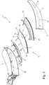
Figure 2 is a partially-exploded perspective view of the automotive light shown inFigure 1 , with parts removed for clarity; -
Figures 3 and4 are, respectively, a plan view and a perspective view of the lighting assembly of the automotive light shown inFigure 1 , with parts removed for clarity; -
Figure 5 is a side view of the lighting assembly shown inFigure 4 , sectioned along section line A-A and with parts removed for clarity; whereas -
Figure 6 is a side view of the lighting assembly shown inFigure 4 , sectioned along section line B-B and with parts removed for clarity. - With reference to
Figures 1 and2 ,number 1 denotes as a whole an automotive lighting appliance particularly suitable to be fixed/incorporated into a vehicle, preferably with the function of lighting the surrounding area of the vehicle, or to signal the presence, the position and/or the movement direction of the vehicle. - In other words, the
lighting appliance 1 is particularly suitable to be fixed to the front or rear part of the vehicle body of an car, van, truck, motorcycle or the like, so as to perform the function of automotive headlight or taillight. - With reference to
Figures 1 and2 , in the example shown, in particular, thelighting appliance 1 is preferably structured to be stably recessed into the rear part of the vehicle body of a car or similar motor vehicle, so as to perform the function of an automotive taillight. - In more detail, the
lighting appliance 1 firstly comprises: a rigid and preferably made of plastic material,rear casing 2 which is roughly basin-shaped, and is preferably structured so as to be at least partially recessed into a seat specifically formed in the rear part of the vehicle body (not shown); a rigid and preferably made of plastic material, a front half-shell 3 which is arranged to close the opening 2a ofrear casing 2, preferably so to simultaneously surface outside of the vehicle body, and is provided with one or more transparent or semi-transparent portions, optionally also coloured; and one or more electrically-powered lighting assemblies, each of which emits light on command and is arranged inside therear casing 2 in a position so as to backlight a corresponding transparent or semi-transparent portion of the front half-shell 3, preferably separately and independently from the other lighting assemblies. Obviously, in a different embodiment, therear casing 2 could also be structured to be simply fixed in a cantilevered manner on the rear part of the vehicle body (not shown). - With reference to
Figures 2 ,3 and4 , additionally thelighting appliance 1 is provided with a main optical axis X which is parallel to the longitudinal axis of the vehicle when thelighting appliance 1 is correctly positioned/fixed on the vehicle body, and one or more of said lighting assemblies is/are preferably structured so as to direct the light outside of thelighting appliance 1 with a predominant component parallel to the main optical axis X of the lighting appliance. - In more detail, with reference to
Figures 1 and2 , in the example shown, the front half-shell 3 is preferably provided with at least one transparent orsemi-transparent portion 4 having a narrow and elongated shape, i.e. substantially ribbon-like, which preferably extends substantially horizontally when thelighting appliance 1 is mounted on the vehicle. - The lighting assembly designed to backlight the transparent or semi-transparent ribbon-
like portion 4 of the lenticular half-shell 3, hereinafter referred to with thenumber 5, is instead placed inside therear casing 2 immediately beneath the transparent or semi-transparent ribbon-like portion 4, so as to be directly facing the same transparent or semi-transparent ribbon-like portion 4 and is structured so as to direct the light produced towards the transparent or semi-transparent ribbon-like portion 4. - Preferably, the
lighting assembly 5 is moreover structured to project/direct the light outside of thelighting appliance 1 through the transparent or semi-transparent ribbon-like portion 4 with a predominant component parallel to the main optical axis X oflighting appliance 1. - In the example shown, in particular, the
rear casing 2 is preferably made of opaque plastic material, preferably via an injection moulding process. The front half-shell 3, on the other hand, is preferably made of transparent or semi-transparent plastic material, such as transparent or semi-transparent polycarbonate or polymethylmethacrylate, also in this case preferably via an injection moulding process. - With reference to Figures from 1 to 6, the
lighting assembly 5 in turn comprises: at least one photoconductive-material light-guide plate 6, which is preferably made of transparent plastic material, and is arranged inside therear casing 2 with itsfront sidewall 7 substantially coplanar and directly facing the transparent or semi-transparent ribbon-like portion 4 of front half-shell 3, preferably substantially for the whole length of the transparent or semi-transparent ribbon-like portion 4, and with itsrear sidewall 8 facing the bottom ofrear casing 2; and an electrically-poweredlight emitting device 9, which is capable of emitting light on command, extends inside therear casing 2 at or close to therear sidewall 8 of light-guide plate 6, and is capable of directing the produced light directly inside the body of the light-guide plate 6 substantially throughout the entire length ofrear sidewall 8. Light that then travels inside the body of light-guide plate 6 by virtue of the same physical principles that regulate the travelling of light inside optical fibre cables, and is emitted from light-guide plate 6 through the platefront sidewall 7 directly towards the transparent or semi-transparent ribbon-like portion 4 of front half-shell 3. - In more detail, the
front sidewall 7 of light-guide plate 6 is preferably arranged locally adjacent/tangent to the transparent or semi-transparent ribbon-like portion 4 of front half-shell 3, preferably substantially throughout the whole length of the transparent or semi-transparent ribbon-like portion 4. - Preferably, the light-
guide plate 6 also extends inside therear casing 2 while remaining locally substantially perpendicular to the transparent or semi-transparent ribbon-like portion 4 of front half-shell 3. Preferably, the lying plane of the light-guide plate 6 is moreover substantially parallel to the main optical axis X of the lighting-appliance 1. - With reference to
Figures 2 ,3 and4 , thelight emitting device 9 on the other hand comprises: a first electrically-powered light source which is located at or close to afirst segment 8a of therear sidewall 8 of light-guide plate 6, and is adapted to direct the light produced directly inside the light-guide plate 6 substantially throughout the whole length ofsegment 8a; and a second electrically-powered light source which is located at or close to asecond segment 8b of therear sidewall 8 of light-guide plate 6 consecutive and complementary to thesegment 8a, and is adapted to direct the light produced directly inside the light-guide plate 6 substantially throughout the whole length ofsegment 8b. - In other words, the
rear sidewall 8 of light-guide plate 6 is divided into at least a first 8a and a second 8b segment complementary to each other. The first light source is capable of lighting thesegment 8a of therear sidewall 8 of light-guide plate 6; the second light source is capable of lighting thesegment 8b of therear sidewall 8 of light-guide plate 6. - Preferably, the length of
segment 8a of therear sidewall 8 of light-guide plate 6 is moreover greater than the length ofsegment 8b. - With reference to
Figures 2 ,3 and4 , in addition, the light-guide plate 6 is provided with a first, preferably substantially rectilinear,sidewall 10 that connects/joins thefront sidewall 7 of light-guide plate 6 to thesegment 8b ofrear sidewall 8. - The first light source is capable of directing the light produced inside the light-
guide plate 6 so that said light directly reaches thefront sidewall 7 of light-guide plate 6. - The second light source, on the other hand, is capable of directing the light produced inside the light-
guide plate 6 so that said light reaches thelateral sidewall 10 of light-guide plate 6 and is there reflected by total internal reflection towards thefront sidewall 7 of light-guide plate 6. - In other words, the light coming from the second light source reaches the
lateral sidewall 10 of light-guide plate 6 with an incidence angle above the limit angle so as to be reflected by total internal reflection towards thefront sidewall 7 of light-guide plate 6. - With reference to
Figures 2 ,3 ,4 ,5 and 6 , in addition, the light-guide plate 6 is divided into at least two plate-like sectors - In more detail, the two plate-
like segments band 13 which preferably takes up the whole thickness of the light-guide plate 6, and which roughly extends from thevertex 14 of the light-guide plate 6 delimited/identified by thefront sidewall 7 and by thelateral sidewall 10 of the plate, up to an intermediate point of therear sidewall 8 of light-guide plate 6 that preferably substantially coincides with the joining point betweensegment 8a andsegment 8b ofrear sidewall 8. - The plate-
like sector 11 is thus shaped so as to substantially form the wholefront sidewall 7 of light-guide plate 6 and thesegment 8a of therear sidewall 8 of light-guide plate 6. - Preferably, the light-
guide plate 6 is moreover substantially quadrilateral in shape, and the plate-like sector 11 is shaped so as to additionally form the secondlateral sidewall 15 of light-guide plate 6 connecting/joining thesegment 8a oflateral sidewall 8 with thefront sidewall 7. - The plate-
like sector 12, in turn, is preferably substantially triangular in shape, and is designed so as to substantially form the wholelateral sidewall 10 of light-guide plate 6 and thesegment 8b of therear sidewall 8 of light-guide plate 6. - With reference to
Figures 2 ,3 ,4 ,5 and 6 , thejoin line 13 between the plate-like sectors guide plate 6 so as to be crossed by the light reflected bylateral sidewall 10 and directed towards thefront sidewall 7 of light-guide plate 6. - In addition, the
join line 13 between the plate-like sectors front sidewall 7 of light-guide plate 6, the light emitted by the second light source oflight emitting device 9, and which is directed directly towards thefront sidewall 7 of light-guide plate 6, while intersecting thejoin line 13 without firstly bouncing on thelateral sidewall 10 of light-guide plate 6. - In other words, the
join line 13 is capable of reflecting, away from thefront sidewall 7 of light-guide plate 6, the light arriving directly from the second light source oflight emitting device 9 and directed towards thefront sidewall 7 of light-guide plate 6. - With reference to
Figures 2 ,3 ,4 ,5 and 6 , in the example shown, in particular, plate-like sector 11 preferably has an extension greater than that of plate-like sector 12. - Preferably, the two plate-
like sectors - In more detail, the plate-
like sector 11 is preferably made of polycarbonate (PC) which has a refractive index approximately equal to about 1,586; whereas the plate-like sector 12 is preferably made of polymethylmethacrylate (PMMA) which in turn has a refractive index equal to about 1.493. - In other words, plate-
like sector 11 preferably has a refractive index greater than the refractive index of plate-like sector 12. - Obviously, the variation of refractive index may also be obtained by using a same plastic material for both plate-
like sectors like sectors - With reference to
Figures 2 ,3 and4 , furthermore, thetransversal join line 13 is preferably substantially rectilinear and preferably extends along the body of light-guide plate 6 with an angle of inclination α with respect to the main optical axis X oflighting appliance 1 preferably greater than 60°. - In the example shown, in particular, the
transversal join line 13 preferably extends towards the joining point betweensegment 8a andsegment 8b of therear sidewall 8 of light-guide plate 6 while remaining locally substantially perpendicular to the main optical axis X oflighting appliance 1. - Preferably, the
transversal join line 13 moreover departs fromvertex 14 of light-guide plate 6, at the joint between thefront sidewall 7 and thelateral sidewall 10 of light-guide plate 6. - With reference to
Figures 2 ,3 , and4 , on the other hand, thelateral sidewall 10 of light-guide plate 6 preferably has a stepped profile. Thelateral sidewall 15 of light-guide plate 6, in turn, is preferably substantially rectilinear, and preferably also locally substantially parallel to the main optical axis X oflighting appliance 1. - With reference to
Figures 2 ,3 ,4 and6 , the first light source of light emittingdevice 9 in turn preferably comprises a first series of LED diodes 18 (acronym of Light Emitting Diode) or other light sources preferably of punctiform type, which are aligned one next to the other to form a row, are placed inside therear casing 2 adjacent to thesegment 8a of therear sidewall 8 of light-guide plate 6, and are oriented so as to direct the light produced directly inside the plate-like sector 11. - Preferably, the row of
LED diodes 18 moreover extends skimmed over one of the two faces of plate-like sector 11, aside and parallel to thesegment 8a of therear sidewall 8 of light-guide plate 6; and eachLED diode 18 is preferably oriented so as to direct the light produced directly inside the plate-like sector 11 towards therear sidewall 8 of light-guide plate 6. Light that then reaches therear sidewall 8 of light-guide plate 6 with an incidence angle above the limit angle so as to be reflected by total internal reflection directly towards thefront sidewall 7 of light-guide plate 6. - The second light source of light emitting
device 9, in turn, preferably comprises a second series of LED diodes 19 (acronym of Light Emitting Diode) or other light sources preferably of punctiform type, which are aligned one next to the other to form a row, are placed inside therear casing 2 adjacent to thesegment 8b of therear sidewall 8 of light-guide plate 6, and are oriented so as to direct the light produced directly inside the plate-like sector 12. - Preferably, the row of
LED diodes 19 moreover extends skimmed over one of the two faces of plate-like sector 12, aside and parallel to thesegment 8b of therear sidewall 8 of light-guide plate 6; and eachLED diode 19 is preferably oriented so as to direct the light produced directly inside the plate-like sector 12 towards therear sidewall 8 of light-guide plate 6. Light that then reaches therear sidewall 8 of light-guide plate 6 with an incidence angle above the limit angle so as to be reflected by total internal reflection directly towards thelateral sidewall 10 of light-guide plate 6. - In the example shown, in particular,
LED diodes single support board 20 which preferably incorporates the power supply and control circuits of the diodes, and is arranged inside therear casing 2 aside and preferably also locally substantially parallel to the light-guide plate 6. - Obviously in a different embodiment, the second light source of light emitting
device 9 may also comprise only oneLED diode 19. - With reference to
Figures 2 ,3 ,4 and6 , preferably thesegment 8a of therear sidewall 8 of light-guide plate 6 is furthermore structured/shaped so as to collimate most of the light rays r1 arriving from theLED diodes 18 and reflected towards thefront sidewall 7 of light-guide plate 6 in a direction substantially parallel to the main optical axis X oflighting appliance 1. - In more detail, in the example shown the plate-
like sector 11 of light-guide plate 6 preferably has, along thesegment 8a ofrear sidewall 8, a plurality of teeth or projectingprotrusions 21 each of which has a curved surface with a preferably substantially parabolic profile. EachLED diode 18 is preferably placed in front of a respective tooth or projectingprotrusion 21 so as to direct the light rays r1 towards the curved surface of the tooth or projectingprotrusion 21 which, in turn, is shaped so as to reflect the light rays r1 towards thefront sidewall 7 of light-guide plate 6, collimating also most of the light rays r1 in a direction substantially parallel to the main optical axis X oflighting appliance 1. - Similarly, the
segment 8b of therear sidewall 8 of light-guide plate 6 is preferably structured/shaped so as to collimate most of the light rays r2 arriving from theLED diodes 19 and directed towards thelateral sidewall 10 of light-guide plate 6 in a predetermined direction that intersects thelateral sidewall 10 with an angle of incidence greater than the limit angle so as to cause the total reflection of the light rays r2 towards thefront sidewall 7 of light-guide plate 6. - In more detail, in the example shown the plate-
like sector 12 of light-guide plate 6 preferably has, along thesegment 8b ofrear sidewall 8, a second series of protruding teeth orprotrusions 22 each of which has a curved surface preferably with a parabolic profile. EachLED diode 19 is preferably placed in front of a respective tooth or projectingprotrusion 22 so as to direct the light rays r2 towards the curved surface of the tooth or projectingprotrusion 22 which, in turn, is shaped so as to reflect the light rays r2 towards thelateral sidewall 10 of light-guide plate 6, preferably collimating the majority of light rays r2 in a predetermined direction that intersects thelateral sidewall 10 of light-guide plate 6 with a predetermined incidence angle greater than the limit angle, thus proving the total reflection of light rays r2 towards thetransversal join line 13 in a second direction substantially perpendicular to the sametransversal join line 13. - Obviously, the light rays r2 can also be reflected towards the
transversal join line 13 in a second direction such that the light rays r2 reach thejoin line 13 with an angle of incidence less than the limit angle. In this way, the light rays r2 coming from thelateral sidewall 10 of light-guide plate 6 can still freely cross thetransversal join line 13 and continue inside the light-guide plate 6 up to thefront sidewall 7 of light-guide plate 6. - Instead, the light rays r3 coming from the LED diode or
LED diodes 19 and going towards thefront sidewall 7 of light-guide plate 6 without having firstly bounced on thelateral sidewall 10, arrive at thejoin line 13 with an incidence angle greater than the limit angle and are therefore reflected away from thefront sidewall 7 of light-guide plate 6, towards thelateral sidewall 10 of light-guide plate 6. - With reference to
Figures 1 and2 , thelighting assembly 5 preferably additionally comprises a supportingstructure 25 preferably made of plastic material and which is located inside therear casing 2, preferably resting on the bottom ofrear casing 2, and is capable to keep the light-guide plate 6 and optionally also thesupport board 20 firmly in position under the front half-shell 3. - Preferably, the supporting
structure 25 is moreover shaped so as to cover/hide the view of some parts oflighting assembly 5. - In more detail, in the example shown the supporting
structure 25 is preferably stably fixed on the bottom ofrear casing 2 and is preferably provided with a pass-throughtubular sheath 26 which protrudes in cantilevered manner from the bottom ofrear casing 2 towards the ribbon-like portion 4 of front half-shell 3 while remaining locally substantially perpendicular to front half-shell 3, and which is shaped so as to accommodate the light-guide plate 6 and optionally a part of thesupport board 20. - In the example shown, in addition, the supporting
structure 25 is preferably made of an opaque plastic material, preferably via an injection moulding process. - The general operation of
lighting appliance 1 is easily inferable from the above, and therefore does not need further explanations. - As regards instead the
lighting assembly 5, the light rays r3 that comes from the LED or LED diode/s 19 and are directed directly towards thefront sidewall 7 of light-guide plate 6 (i.e. travelling towards thefront sidewall 7 without having previously bounced on thelateral sidewall 10 of light-guide plate 6), arrive on thejoin line 13 between the plate-like sectors lateral sidewall 10 of light-guide plate 6. - The light rays r2 that are instead reflected by the
lateral sidewall 10 of light-guide plate 6, arrive at thejoin line 13 between the plate-like sectors like sector 12 to the plate-like sector 11, and then proceed towards thefront sidewall 7 of light-guide plate 6. - The advantages correlated to the particular structure of
lighting assembly 5 are numerous. - Firstly, the presence of
join line 13 allows to eliminate the excess lighting on the section/segment of thefront sidewall 7 of light-guide plate 6 adjacent to thevertex 14 of light-guide plate 6, thus making the intensity of the light coming out from the light-guide plate 6 uniform throughout the whole length of thefront sidewall 7 of the plate. - In addition, the stepped profile of the
lateral sidewall 10 of light-guide plate 6 allows to minimize the extension of plate-like sector 12, thus reducing the overall extension of the light-guide plate 6 and, consequently, reducing the overall size of therear casing 2. - It is finally clear that modifications and variants may be made to the
lighting appliance 1 described above without however departing from the scope of the present invention. - For example, in a different embodiment, the
LED diodes 18 forming the first light source of light emittingdevice 9 can be placed in abutment directly against thesegment 8a of therear sidewall 8 of light-guide plate 6, one spaced apart aside the other. Likewise, theLED diodes 19 forming the second light source of light emittingdevice 9 can be arranged in abutment directly against thesegment 8b of therear sidewall 8 of light-guide plate 6, one spaced apart aside the other. - In a different embodiment, furthermore, at least one of the two light sources of light emitting
device 9 may comprise, in place ofLED diodes 18, 19: a photoconductive material, light-guide bar preferably made of transparent plastic material and which extends inside therear casing 2, skimming over thesegment 8a and/or 8b of therear sidewall 8 of light-guide plate 6; and one or more remote LED diodes which are located at one of the two ends of the light-guide bar, so as to direct the produced light inside the light-guide bar. The light-guide bar is structured so as to collect the light emitted by the remote LED diode/s and to convey it, in known manner, up to thesegment 8a and/or tosegment 8b of therear sidewall 8 of the light-guide plate 6.
Claims (16)
- An automotive lighting appliance (1) comprising: a substantially basin-shaped rear casing (2); a front half-shell (3) which is arranged to close the opening (2a) of the rear casing (2), and is provided with at least one transparent or semi-transparent portion (4); and at least a first lighting assembly (5) which emits light on command, and is located inside the rear casing (2) so as to be able to backlight said transparent or semi-transparent portion (4) of the front half-shell (3);said lighting assembly (5) comprising: at least one light-guide plate (6) made of photoconductive material, which is arranged inside the rear casing (2) with a front sidewall (7) of the plate facing said transparent or semi-transparent portion (4) of the front half-shell (3), and with a rear sidewall (8) of the plate facing the rear casing (2); and light emitting means (9) which are located inside the rear casing (2) at or close to the rear sidewall (8) of the light-guide plate (6), and are adapted to direct the light produced inside the light-guide plate (6) so that said light travels inside the light-guide plate (6) towards the front sidewall (7) of the light-guide plate (6) and is emitted from the light-guide plate (6) through the same front sidewall (7) directed towards said transparent or semi-transparent portion (4) of the front half-shell (3);wherein the light-guide plate (6) is divided into at least a first (11) and a second (12) plate-like sector co-planar to each other, which are arranged mutually adjacent and contiguous, are made of photoconductive materials with refractive indices different from each other, and are stably joined to each other to form a single plate-like body/piece along a join line (13) that extends substantially from the vertex (14) of the light-guide plate (6) delimited by the front sidewall (7) and by a first lateral sidewall (10) of the light-guide plate (6), to an intermediate point of the rear sidewall (8) of the light-guide plate (6).
- Automotive lighting appliance according to Claim 1, characterised in that the light emitting means (9) comprise a first light source (18) which is located inside the rear casing (2) at or close to a first segment (8a) of the rear sidewall (8) of the light-guide plate (6), and is adapted to direct the light produced (r1) inside the first plate-like sector (11) of the light-guide plate (6), so that said light (r1) travels inside the light-guide plate (6) towards said front sidewall (7).
- Automotive lighting appliance according to Claim 1 or 2, characterised in that the light emitting means (9) comprise a second light source (19), which is located inside the rear casing (2) at or close to a second segment (8b) of the rear sidewall (8) of the light-guide plate (6), and is capable of directing the light produced (r2) inside the second plate-like sector (12) of the light-guide plate (6), so that said light (r2) travels inside the light-guide plate (6) towards said first lateral sidewall (10) of the light-guide plate (6), and is reflected thereby towards the front sidewall (7) of the light-guide plate (6) .
- Automotive lighting appliance according to Claim 3, characterised in that the join line (13) between said first (11) and second plate-like sector (12) is adapted to be passed through by the light (r2) reflected by the first lateral sidewall (10) of the light-guide plate (6) towards the front sidewall (7) of the same light-guide plate (6), and to reflect, away from the front sidewall (7) of the light-guide plate (6), the light (r3) coming from said second light source (19) and directed directly towards the front sidewall (7) of the light-guide plate (6) intersecting the join line (13) without having first bounced off the first lateral sidewall (10) of the light-guide plate (6).
- Automotive lighting appliance according to Claim 3 or 4, characterised in that the join line (13) between said first (11) and second plate-like sector (12) reaches the rear sidewall (8) of the light-guide plate (6) substantially at the joining point between said first (8a) and said second (8b) segment of the rear sidewall (8) of the light-guide plate (6).
- Automotive lighting appliance according to any one of the preceding claims, characterised in that the join line (13) between said first (11) and second (12) plate-like sectors is substantially rectilinear.
- Automotive lighting appliance according to Claim 6, characterised in that the join line (13) extends on the light-guide plate (6) with an angle of inclination (α) greater than 60° with respect to a lighting-appliance main optical axis (X) which is arranged substantially parallel to the longitudinal axis of the vehicle when the lighting appliance (1) is placed on the vehicle body.
- Automotive lighting appliance according to Claim 7, characterised in that the join line (13) extends on the light-guide plate (6) remaining substantially perpendicular to said main optical axis (X).
- Automotive lighting appliance according to any one of the preceding claims, characterised in that said first lateral sidewall (10) of the light-guide plate (6) has a stepped profile.
- Automotive lighting appliance according to any one of the preceding claims, characterised in that said first (11) and second (12) plate-like sectors are made of plastic material.
- Automotive lighting appliance according to claim 10, characterised in that said first (11) and second plate-like sectors (12) are made via a co-injection moulding process.
- Automotive lighting appliance according to any one of Claims 2 to 11, characterised in that the first light source (18) comprises a series of LED diodes (18), which are placed inside the rear casing (2) adjacent to the first segment (8a) of the rear sidewall (8) of the light-guide plate (6), and are oriented so as to direct the light produced directly inside the first plate-like sector (11).
- Automotive lighting appliance according to Claim 12, characterised in that the first segment (8a) of the rear sidewall (8) of the light-guide plate (6) is shaped/structured so as to collimate a part of the light rays (r1) coming from said series of LED diodes (18) and directed towards the front sidewall (7) of the light-guide plate (6), in a direction substantially parallel to a lighting-appliance main optical axis (X) which is arranged substantially parallel to the longitudinal axis of the vehicle when the lighting appliance (1) is placed on the vehicle body.
- Automotive lighting appliance according to any one of Claims 3 to 13, characterised in that the second light source (19) comprises one or more LED diodes (19) which are placed inside the rear casing (2) against the second segment (8b) of the rear sidewall (8) of the light-guide plate (6), and are oriented so as to direct the light produced directly inside the second plate-like sector (12).
- Automotive lighting appliance according to Claim 14, characterised in that the second segment (8b) of the rear sidewall (8) of the light-guide plate (6) is structured/shaped so as to collimate a part of the light rays (r2) coming from the LED diode or diodes (19) of the second light source (19) and reflected towards the lateral sidewall (10) of the light-guide plate (6), in a direction that intersects said lateral sidewall (10) with an angle of incidence greater than the limit angle, so as to cause the total reflection of the light rays (r2) towards the join line (13) and towards the front sidewall (7) of the light-guide plate (6).
- Automotive light according to any one of the preceding claims, characterised in that the transparent or semi-transparent portion (4) of the front half-shell (3) is substantially ribbon-like.
Priority Applications (1)
| Application Number | Priority Date | Filing Date | Title |
|---|---|---|---|
| PL17172969T PL3248840T3 (en) | 2016-05-25 | 2017-05-25 | Automotive lighting appliance |
Applications Claiming Priority (1)
| Application Number | Priority Date | Filing Date | Title |
|---|---|---|---|
| ITUA2016A003800A ITUA20163800A1 (en) | 2016-05-25 | 2016-05-25 | AUTOMOTIVE LIGHTING APPLIANCE |
Publications (2)
| Publication Number | Publication Date |
|---|---|
| EP3248840A1 EP3248840A1 (en) | 2017-11-29 |
| EP3248840B1 true EP3248840B1 (en) | 2021-11-03 |
Family
ID=57113542
Family Applications (1)
| Application Number | Title | Priority Date | Filing Date |
|---|---|---|---|
| EP17172969.2A Active EP3248840B1 (en) | 2016-05-25 | 2017-05-25 | Automotive lighting appliance |
Country Status (4)
| Country | Link |
|---|---|
| EP (1) | EP3248840B1 (en) |
| ES (1) | ES2901988T3 (en) |
| IT (1) | ITUA20163800A1 (en) |
| PL (1) | PL3248840T3 (en) |
Families Citing this family (7)
| Publication number | Priority date | Publication date | Assignee | Title |
|---|---|---|---|---|
| ES2832877T3 (en) * | 2017-12-01 | 2021-06-11 | Marelli Automotive Lighting Italy Spa | Automotive lighting unit |
| JP2020024867A (en) * | 2018-08-08 | 2020-02-13 | 株式会社小糸製作所 | Vehicular lighting fixture |
| JP7483523B2 (en) * | 2020-06-23 | 2024-05-15 | スタンレー電気株式会社 | Vehicle lighting fixtures |
| JP7517888B2 (en) * | 2020-07-20 | 2024-07-17 | スタンレー電気株式会社 | Vehicle lighting fixtures |
| FR3120111A1 (en) * | 2021-02-19 | 2022-08-26 | Psa Automobiles Sa | Light guide for motor vehicle optical unit, associated optical unit and motor vehicle |
| IT202100008909A1 (en) | 2021-04-09 | 2022-10-09 | Marelli Automotive Lighting Italy S P A Con Socio Unico | LIGHTING DEVICE FOR VEHICLES, IN PARTICULAR LED |
| FR3141991A1 (en) * | 2022-11-10 | 2024-05-17 | Psa Automobiles Sa | Flat light guide for signaling lighting of a motor vehicle. |
Family Cites Families (5)
| Publication number | Priority date | Publication date | Assignee | Title |
|---|---|---|---|---|
| JP2013161626A (en) * | 2012-02-03 | 2013-08-19 | Harison Toshiba Lighting Corp | Strip-shaped lighting device |
| DE102014206238A1 (en) * | 2013-06-22 | 2014-12-24 | Volkswagen Aktiengesellschaft | Motor vehicle with a lighting device |
| JP6109315B2 (en) * | 2013-08-12 | 2017-04-05 | 三菱電機株式会社 | Headlight device |
| DE102014110225A1 (en) * | 2014-07-21 | 2016-01-21 | Osram Opto Semiconductors Gmbh | vehicle light |
| FR3024528B1 (en) * | 2014-07-31 | 2016-09-02 | Valeo Vision | LUMINOUS MODULE, IN PARTICULAR LIGHTING AND / OR SIGNALING FOR MOTOR VEHICLE |
-
2016
- 2016-05-25 IT ITUA2016A003800A patent/ITUA20163800A1/en unknown
-
2017
- 2017-05-25 ES ES17172969T patent/ES2901988T3/en active Active
- 2017-05-25 PL PL17172969T patent/PL3248840T3/en unknown
- 2017-05-25 EP EP17172969.2A patent/EP3248840B1/en active Active
Also Published As
| Publication number | Publication date |
|---|---|
| ITUA20163800A1 (en) | 2017-11-25 |
| EP3248840A1 (en) | 2017-11-29 |
| ES2901988T3 (en) | 2022-03-24 |
| PL3248840T3 (en) | 2022-03-28 |
Similar Documents
| Publication | Publication Date | Title |
|---|---|---|
| EP3436739B1 (en) | Automotive lighting unit with a light guide plate | |
| EP3248840A1 (en) | Automotive lighting appliance | |
| US9140422B2 (en) | Automotive rear light | |
| EP3071878B1 (en) | Automotive lamp | |
| EP2681485B1 (en) | Automotive lighting unit | |
| EP2840300B1 (en) | Automotive light | |
| JP2013037963A (en) | Vehicular lamp | |
| CN107107815A (en) | Additional brake lights for vehicles | |
| EP2731824A1 (en) | Automotive light | |
| US12240374B2 (en) | Automotive light | |
| KR102899325B1 (en) | Lamp for vehicle | |
| CN110131672B (en) | Vehicle lamps | |
| EP4023935B1 (en) | Automotive light | |
| EP4206523B1 (en) | Automotive light | |
| EP3839329B1 (en) | Automotive lighting appliance | |
| JP5280834B2 (en) | Side turn lamps for vehicle door mirrors | |
| KR20100066926A (en) | Lamp for vehicles |
Legal Events
| Date | Code | Title | Description |
|---|---|---|---|
| PUAI | Public reference made under article 153(3) epc to a published international application that has entered the european phase |
Free format text: ORIGINAL CODE: 0009012 |
|
| STAA | Information on the status of an ep patent application or granted ep patent |
Free format text: STATUS: THE APPLICATION HAS BEEN PUBLISHED |
|
| AK | Designated contracting states |
Kind code of ref document: A1 Designated state(s): AL AT BE BG CH CY CZ DE DK EE ES FI FR GB GR HR HU IE IS IT LI LT LU LV MC MK MT NL NO PL PT RO RS SE SI SK SM TR |
|
| AX | Request for extension of the european patent |
Extension state: BA ME |
|
| STAA | Information on the status of an ep patent application or granted ep patent |
Free format text: STATUS: REQUEST FOR EXAMINATION WAS MADE |
|
| 17P | Request for examination filed |
Effective date: 20180528 |
|
| RBV | Designated contracting states (corrected) |
Designated state(s): AL AT BE BG CH CY CZ DE DK EE ES FI FR GB GR HR HU IE IS IT LI LT LU LV MC MK MT NL NO PL PT RO RS SE SI SK SM TR |
|
| GRAP | Despatch of communication of intention to grant a patent |
Free format text: ORIGINAL CODE: EPIDOSNIGR1 |
|
| STAA | Information on the status of an ep patent application or granted ep patent |
Free format text: STATUS: GRANT OF PATENT IS INTENDED |
|
| RIC1 | Information provided on ipc code assigned before grant |
Ipc: F21V 8/00 20060101ALI20210422BHEP Ipc: G02B 6/00 20060101ALI20210422BHEP Ipc: F21S 43/249 20180101ALI20210422BHEP Ipc: F21S 43/243 20180101ALI20210422BHEP Ipc: F21S 43/239 20180101ALI20210422BHEP Ipc: F21S 43/14 20180101ALI20210422BHEP Ipc: B60Q 1/26 20060101AFI20210422BHEP |
|
| INTG | Intention to grant announced |
Effective date: 20210526 |
|
| GRAS | Grant fee paid |
Free format text: ORIGINAL CODE: EPIDOSNIGR3 |
|
| GRAA | (expected) grant |
Free format text: ORIGINAL CODE: 0009210 |
|
| STAA | Information on the status of an ep patent application or granted ep patent |
Free format text: STATUS: THE PATENT HAS BEEN GRANTED |
|
| RAP3 | Party data changed (applicant data changed or rights of an application transferred) |
Owner name: MARELLI AUTOMOTIVE LIGHTING ITALY S.P.A. |
|
| AK | Designated contracting states |
Kind code of ref document: B1 Designated state(s): AL AT BE BG CH CY CZ DE DK EE ES FI FR GB GR HR HU IE IS IT LI LT LU LV MC MK MT NL NO PL PT RO RS SE SI SK SM TR |
|
| REG | Reference to a national code |
Ref country code: GB Ref legal event code: FG4D |
|
| REG | Reference to a national code |
Ref country code: AT Ref legal event code: REF Ref document number: 1443678 Country of ref document: AT Kind code of ref document: T Effective date: 20211115 Ref country code: CH Ref legal event code: EP |
|
| REG | Reference to a national code |
Ref country code: DE Ref legal event code: R096 Ref document number: 602017048594 Country of ref document: DE |
|
| REG | Reference to a national code |
Ref country code: IE Ref legal event code: FG4D |
|
| REG | Reference to a national code |
Ref country code: LT Ref legal event code: MG9D |
|
| REG | Reference to a national code |
Ref country code: NL Ref legal event code: MP Effective date: 20211103 |
|
| REG | Reference to a national code |
Ref country code: AT Ref legal event code: MK05 Ref document number: 1443678 Country of ref document: AT Kind code of ref document: T Effective date: 20211103 |
|
| REG | Reference to a national code |
Ref country code: ES Ref legal event code: FG2A Ref document number: 2901988 Country of ref document: ES Kind code of ref document: T3 Effective date: 20220324 |
|
| PG25 | Lapsed in a contracting state [announced via postgrant information from national office to epo] |
Ref country code: RS Free format text: LAPSE BECAUSE OF FAILURE TO SUBMIT A TRANSLATION OF THE DESCRIPTION OR TO PAY THE FEE WITHIN THE PRESCRIBED TIME-LIMIT Effective date: 20211103 Ref country code: LT Free format text: LAPSE BECAUSE OF FAILURE TO SUBMIT A TRANSLATION OF THE DESCRIPTION OR TO PAY THE FEE WITHIN THE PRESCRIBED TIME-LIMIT Effective date: 20211103 Ref country code: FI Free format text: LAPSE BECAUSE OF FAILURE TO SUBMIT A TRANSLATION OF THE DESCRIPTION OR TO PAY THE FEE WITHIN THE PRESCRIBED TIME-LIMIT Effective date: 20211103 Ref country code: BG Free format text: LAPSE BECAUSE OF FAILURE TO SUBMIT A TRANSLATION OF THE DESCRIPTION OR TO PAY THE FEE WITHIN THE PRESCRIBED TIME-LIMIT Effective date: 20220203 Ref country code: AT Free format text: LAPSE BECAUSE OF FAILURE TO SUBMIT A TRANSLATION OF THE DESCRIPTION OR TO PAY THE FEE WITHIN THE PRESCRIBED TIME-LIMIT Effective date: 20211103 |
|
| PG25 | Lapsed in a contracting state [announced via postgrant information from national office to epo] |
Ref country code: IS Free format text: LAPSE BECAUSE OF FAILURE TO SUBMIT A TRANSLATION OF THE DESCRIPTION OR TO PAY THE FEE WITHIN THE PRESCRIBED TIME-LIMIT Effective date: 20220303 Ref country code: SE Free format text: LAPSE BECAUSE OF FAILURE TO SUBMIT A TRANSLATION OF THE DESCRIPTION OR TO PAY THE FEE WITHIN THE PRESCRIBED TIME-LIMIT Effective date: 20211103 Ref country code: PT Free format text: LAPSE BECAUSE OF FAILURE TO SUBMIT A TRANSLATION OF THE DESCRIPTION OR TO PAY THE FEE WITHIN THE PRESCRIBED TIME-LIMIT Effective date: 20220303 Ref country code: NO Free format text: LAPSE BECAUSE OF FAILURE TO SUBMIT A TRANSLATION OF THE DESCRIPTION OR TO PAY THE FEE WITHIN THE PRESCRIBED TIME-LIMIT Effective date: 20220203 Ref country code: NL Free format text: LAPSE BECAUSE OF FAILURE TO SUBMIT A TRANSLATION OF THE DESCRIPTION OR TO PAY THE FEE WITHIN THE PRESCRIBED TIME-LIMIT Effective date: 20211103 Ref country code: LV Free format text: LAPSE BECAUSE OF FAILURE TO SUBMIT A TRANSLATION OF THE DESCRIPTION OR TO PAY THE FEE WITHIN THE PRESCRIBED TIME-LIMIT Effective date: 20211103 Ref country code: HR Free format text: LAPSE BECAUSE OF FAILURE TO SUBMIT A TRANSLATION OF THE DESCRIPTION OR TO PAY THE FEE WITHIN THE PRESCRIBED TIME-LIMIT Effective date: 20211103 Ref country code: GR Free format text: LAPSE BECAUSE OF FAILURE TO SUBMIT A TRANSLATION OF THE DESCRIPTION OR TO PAY THE FEE WITHIN THE PRESCRIBED TIME-LIMIT Effective date: 20220204 |
|
| PG25 | Lapsed in a contracting state [announced via postgrant information from national office to epo] |
Ref country code: SM Free format text: LAPSE BECAUSE OF FAILURE TO SUBMIT A TRANSLATION OF THE DESCRIPTION OR TO PAY THE FEE WITHIN THE PRESCRIBED TIME-LIMIT Effective date: 20211103 Ref country code: SK Free format text: LAPSE BECAUSE OF FAILURE TO SUBMIT A TRANSLATION OF THE DESCRIPTION OR TO PAY THE FEE WITHIN THE PRESCRIBED TIME-LIMIT Effective date: 20211103 Ref country code: RO Free format text: LAPSE BECAUSE OF FAILURE TO SUBMIT A TRANSLATION OF THE DESCRIPTION OR TO PAY THE FEE WITHIN THE PRESCRIBED TIME-LIMIT Effective date: 20211103 Ref country code: EE Free format text: LAPSE BECAUSE OF FAILURE TO SUBMIT A TRANSLATION OF THE DESCRIPTION OR TO PAY THE FEE WITHIN THE PRESCRIBED TIME-LIMIT Effective date: 20211103 Ref country code: DK Free format text: LAPSE BECAUSE OF FAILURE TO SUBMIT A TRANSLATION OF THE DESCRIPTION OR TO PAY THE FEE WITHIN THE PRESCRIBED TIME-LIMIT Effective date: 20211103 |
|
| REG | Reference to a national code |
Ref country code: DE Ref legal event code: R097 Ref document number: 602017048594 Country of ref document: DE |
|
| PLBE | No opposition filed within time limit |
Free format text: ORIGINAL CODE: 0009261 |
|
| STAA | Information on the status of an ep patent application or granted ep patent |
Free format text: STATUS: NO OPPOSITION FILED WITHIN TIME LIMIT |
|
| 26N | No opposition filed |
Effective date: 20220804 |
|
| PG25 | Lapsed in a contracting state [announced via postgrant information from national office to epo] |
Ref country code: AL Free format text: LAPSE BECAUSE OF FAILURE TO SUBMIT A TRANSLATION OF THE DESCRIPTION OR TO PAY THE FEE WITHIN THE PRESCRIBED TIME-LIMIT Effective date: 20211103 |
|
| PG25 | Lapsed in a contracting state [announced via postgrant information from national office to epo] |
Ref country code: SI Free format text: LAPSE BECAUSE OF FAILURE TO SUBMIT A TRANSLATION OF THE DESCRIPTION OR TO PAY THE FEE WITHIN THE PRESCRIBED TIME-LIMIT Effective date: 20211103 |
|
| REG | Reference to a national code |
Ref country code: CH Ref legal event code: PL |
|
| REG | Reference to a national code |
Ref country code: BE Ref legal event code: MM Effective date: 20220531 |
|
| PG25 | Lapsed in a contracting state [announced via postgrant information from national office to epo] |
Ref country code: MC Free format text: LAPSE BECAUSE OF FAILURE TO SUBMIT A TRANSLATION OF THE DESCRIPTION OR TO PAY THE FEE WITHIN THE PRESCRIBED TIME-LIMIT Effective date: 20211103 Ref country code: LU Free format text: LAPSE BECAUSE OF NON-PAYMENT OF DUE FEES Effective date: 20220525 Ref country code: LI Free format text: LAPSE BECAUSE OF NON-PAYMENT OF DUE FEES Effective date: 20220531 Ref country code: CH Free format text: LAPSE BECAUSE OF NON-PAYMENT OF DUE FEES Effective date: 20220531 |
|
| PG25 | Lapsed in a contracting state [announced via postgrant information from national office to epo] |
Ref country code: IE Free format text: LAPSE BECAUSE OF NON-PAYMENT OF DUE FEES Effective date: 20220525 |
|
| PG25 | Lapsed in a contracting state [announced via postgrant information from national office to epo] |
Ref country code: BE Free format text: LAPSE BECAUSE OF NON-PAYMENT OF DUE FEES Effective date: 20220531 |
|
| PG25 | Lapsed in a contracting state [announced via postgrant information from national office to epo] |
Ref country code: HU Free format text: LAPSE BECAUSE OF FAILURE TO SUBMIT A TRANSLATION OF THE DESCRIPTION OR TO PAY THE FEE WITHIN THE PRESCRIBED TIME-LIMIT; INVALID AB INITIO Effective date: 20170525 |
|
| PG25 | Lapsed in a contracting state [announced via postgrant information from national office to epo] |
Ref country code: MK Free format text: LAPSE BECAUSE OF FAILURE TO SUBMIT A TRANSLATION OF THE DESCRIPTION OR TO PAY THE FEE WITHIN THE PRESCRIBED TIME-LIMIT Effective date: 20211103 Ref country code: CY Free format text: LAPSE BECAUSE OF FAILURE TO SUBMIT A TRANSLATION OF THE DESCRIPTION OR TO PAY THE FEE WITHIN THE PRESCRIBED TIME-LIMIT Effective date: 20211103 |
|
| PGFP | Annual fee paid to national office [announced via postgrant information from national office to epo] |
Ref country code: GB Payment date: 20240419 Year of fee payment: 8 |
|
| PGFP | Annual fee paid to national office [announced via postgrant information from national office to epo] |
Ref country code: ES Payment date: 20240603 Year of fee payment: 8 |
|
| PGFP | Annual fee paid to national office [announced via postgrant information from national office to epo] |
Ref country code: CZ Payment date: 20240423 Year of fee payment: 8 |
|
| PGFP | Annual fee paid to national office [announced via postgrant information from national office to epo] |
Ref country code: PL Payment date: 20240423 Year of fee payment: 8 |
|
| PGFP | Annual fee paid to national office [announced via postgrant information from national office to epo] |
Ref country code: TR Payment date: 20240430 Year of fee payment: 8 |
|
| PG25 | Lapsed in a contracting state [announced via postgrant information from national office to epo] |
Ref country code: MT Free format text: LAPSE BECAUSE OF FAILURE TO SUBMIT A TRANSLATION OF THE DESCRIPTION OR TO PAY THE FEE WITHIN THE PRESCRIBED TIME-LIMIT Effective date: 20211103 |
|
| PGFP | Annual fee paid to national office [announced via postgrant information from national office to epo] |
Ref country code: DE Payment date: 20250423 Year of fee payment: 9 |
|
| PGFP | Annual fee paid to national office [announced via postgrant information from national office to epo] |
Ref country code: IT Payment date: 20250423 Year of fee payment: 9 |
|
| PGFP | Annual fee paid to national office [announced via postgrant information from national office to epo] |
Ref country code: FR Payment date: 20250423 Year of fee payment: 9 |
|
| PG25 | Lapsed in a contracting state [announced via postgrant information from national office to epo] |
Ref country code: CZ Free format text: LAPSE BECAUSE OF NON-PAYMENT OF DUE FEES Effective date: 20250525 |
|
| GBPC | Gb: european patent ceased through non-payment of renewal fee |
Effective date: 20250525 |
|
| PG25 | Lapsed in a contracting state [announced via postgrant information from national office to epo] |
Ref country code: GB Free format text: LAPSE BECAUSE OF NON-PAYMENT OF DUE FEES Effective date: 20250525 |