EP3248768A1 - A method of correcting an inappropriate countersink in a composite component - Google Patents
A method of correcting an inappropriate countersink in a composite component Download PDFInfo
- Publication number
- EP3248768A1 EP3248768A1 EP16400018.4A EP16400018A EP3248768A1 EP 3248768 A1 EP3248768 A1 EP 3248768A1 EP 16400018 A EP16400018 A EP 16400018A EP 3248768 A1 EP3248768 A1 EP 3248768A1
- Authority
- EP
- European Patent Office
- Prior art keywords
- countersink
- repair patch
- inappropriate
- composite component
- opening
- Prior art date
- Legal status (The legal status is an assumption and is not a legal conclusion. Google has not performed a legal analysis and makes no representation as to the accuracy of the status listed.)
- Granted
Links
Images


Classifications
-
- B—PERFORMING OPERATIONS; TRANSPORTING
- B29—WORKING OF PLASTICS; WORKING OF SUBSTANCES IN A PLASTIC STATE IN GENERAL
- B29C—SHAPING OR JOINING OF PLASTICS; SHAPING OF MATERIAL IN A PLASTIC STATE, NOT OTHERWISE PROVIDED FOR; AFTER-TREATMENT OF THE SHAPED PRODUCTS, e.g. REPAIRING
- B29C73/00—Repairing of articles made from plastics or substances in a plastic state, e.g. of articles shaped or produced by using techniques covered by this subclass or subclass B29D
- B29C73/04—Repairing of articles made from plastics or substances in a plastic state, e.g. of articles shaped or produced by using techniques covered by this subclass or subclass B29D using preformed elements
- B29C73/10—Repairing of articles made from plastics or substances in a plastic state, e.g. of articles shaped or produced by using techniques covered by this subclass or subclass B29D using preformed elements using patches sealing on the surface of the article
- B29C73/105—Repairing of articles made from plastics or substances in a plastic state, e.g. of articles shaped or produced by using techniques covered by this subclass or subclass B29D using preformed elements using patches sealing on the surface of the article provided with a centering element
-
- B—PERFORMING OPERATIONS; TRANSPORTING
- B29—WORKING OF PLASTICS; WORKING OF SUBSTANCES IN A PLASTIC STATE IN GENERAL
- B29C—SHAPING OR JOINING OF PLASTICS; SHAPING OF MATERIAL IN A PLASTIC STATE, NOT OTHERWISE PROVIDED FOR; AFTER-TREATMENT OF THE SHAPED PRODUCTS, e.g. REPAIRING
- B29C73/00—Repairing of articles made from plastics or substances in a plastic state, e.g. of articles shaped or produced by using techniques covered by this subclass or subclass B29D
- B29C73/04—Repairing of articles made from plastics or substances in a plastic state, e.g. of articles shaped or produced by using techniques covered by this subclass or subclass B29D using preformed elements
- B29C73/06—Repairing of articles made from plastics or substances in a plastic state, e.g. of articles shaped or produced by using techniques covered by this subclass or subclass B29D using preformed elements using plugs sealing in the hole
-
- B—PERFORMING OPERATIONS; TRANSPORTING
- B29—WORKING OF PLASTICS; WORKING OF SUBSTANCES IN A PLASTIC STATE IN GENERAL
- B29C—SHAPING OR JOINING OF PLASTICS; SHAPING OF MATERIAL IN A PLASTIC STATE, NOT OTHERWISE PROVIDED FOR; AFTER-TREATMENT OF THE SHAPED PRODUCTS, e.g. REPAIRING
- B29C73/00—Repairing of articles made from plastics or substances in a plastic state, e.g. of articles shaped or produced by using techniques covered by this subclass or subclass B29D
- B29C73/04—Repairing of articles made from plastics or substances in a plastic state, e.g. of articles shaped or produced by using techniques covered by this subclass or subclass B29D using preformed elements
- B29C73/10—Repairing of articles made from plastics or substances in a plastic state, e.g. of articles shaped or produced by using techniques covered by this subclass or subclass B29D using preformed elements using patches sealing on the surface of the article
-
- B—PERFORMING OPERATIONS; TRANSPORTING
- B29—WORKING OF PLASTICS; WORKING OF SUBSTANCES IN A PLASTIC STATE IN GENERAL
- B29C—SHAPING OR JOINING OF PLASTICS; SHAPING OF MATERIAL IN A PLASTIC STATE, NOT OTHERWISE PROVIDED FOR; AFTER-TREATMENT OF THE SHAPED PRODUCTS, e.g. REPAIRING
- B29C73/00—Repairing of articles made from plastics or substances in a plastic state, e.g. of articles shaped or produced by using techniques covered by this subclass or subclass B29D
- B29C73/24—Apparatus or accessories not otherwise provided for
- B29C73/30—Apparatus or accessories not otherwise provided for for local pressing or local heating
-
- B—PERFORMING OPERATIONS; TRANSPORTING
- B32—LAYERED PRODUCTS
- B32B—LAYERED PRODUCTS, i.e. PRODUCTS BUILT-UP OF STRATA OF FLAT OR NON-FLAT, e.g. CELLULAR OR HONEYCOMB, FORM
- B32B27/00—Layered products comprising a layer of synthetic resin
- B32B27/32—Layered products comprising a layer of synthetic resin comprising polyolefins
- B32B27/322—Layered products comprising a layer of synthetic resin comprising polyolefins comprising halogenated polyolefins, e.g. PTFE
-
- B—PERFORMING OPERATIONS; TRANSPORTING
- B32—LAYERED PRODUCTS
- B32B—LAYERED PRODUCTS, i.e. PRODUCTS BUILT-UP OF STRATA OF FLAT OR NON-FLAT, e.g. CELLULAR OR HONEYCOMB, FORM
- B32B37/00—Methods or apparatus for laminating, e.g. by curing or by ultrasonic bonding
- B32B37/10—Methods or apparatus for laminating, e.g. by curing or by ultrasonic bonding characterised by the pressing technique, e.g. using action of vacuum or fluid pressure
-
- B—PERFORMING OPERATIONS; TRANSPORTING
- B29—WORKING OF PLASTICS; WORKING OF SUBSTANCES IN A PLASTIC STATE IN GENERAL
- B29K—INDEXING SCHEME ASSOCIATED WITH SUBCLASSES B29B, B29C OR B29D, RELATING TO MOULDING MATERIALS OR TO MATERIALS FOR MOULDS, REINFORCEMENTS, FILLERS OR PREFORMED PARTS, e.g. INSERTS
- B29K2027/00—Use of polyvinylhalogenides or derivatives thereof as moulding material
- B29K2027/12—Use of polyvinylhalogenides or derivatives thereof as moulding material containing fluorine
- B29K2027/18—PTFE, i.e. polytetrafluoroethylene, e.g. ePTFE, i.e. expanded polytetrafluoroethylene
-
- B—PERFORMING OPERATIONS; TRANSPORTING
- B29—WORKING OF PLASTICS; WORKING OF SUBSTANCES IN A PLASTIC STATE IN GENERAL
- B29K—INDEXING SCHEME ASSOCIATED WITH SUBCLASSES B29B, B29C OR B29D, RELATING TO MOULDING MATERIALS OR TO MATERIALS FOR MOULDS, REINFORCEMENTS, FILLERS OR PREFORMED PARTS, e.g. INSERTS
- B29K2105/00—Condition, form or state of moulded material or of the material to be shaped
- B29K2105/0097—Glues or adhesives, e.g. hot melts or thermofusible adhesives
-
- B—PERFORMING OPERATIONS; TRANSPORTING
- B29—WORKING OF PLASTICS; WORKING OF SUBSTANCES IN A PLASTIC STATE IN GENERAL
- B29K—INDEXING SCHEME ASSOCIATED WITH SUBCLASSES B29B, B29C OR B29D, RELATING TO MOULDING MATERIALS OR TO MATERIALS FOR MOULDS, REINFORCEMENTS, FILLERS OR PREFORMED PARTS, e.g. INSERTS
- B29K2105/00—Condition, form or state of moulded material or of the material to be shaped
- B29K2105/25—Solid
- B29K2105/253—Preform
- B29K2105/256—Sheets, plates, blanks or films
-
- B—PERFORMING OPERATIONS; TRANSPORTING
- B32—LAYERED PRODUCTS
- B32B—LAYERED PRODUCTS, i.e. PRODUCTS BUILT-UP OF STRATA OF FLAT OR NON-FLAT, e.g. CELLULAR OR HONEYCOMB, FORM
- B32B2327/00—Polyvinylhalogenides
- B32B2327/12—Polyvinylhalogenides containing fluorine
- B32B2327/18—PTFE, i.e. polytetrafluoroethylene
-
- B—PERFORMING OPERATIONS; TRANSPORTING
- B32—LAYERED PRODUCTS
- B32B—LAYERED PRODUCTS, i.e. PRODUCTS BUILT-UP OF STRATA OF FLAT OR NON-FLAT, e.g. CELLULAR OR HONEYCOMB, FORM
- B32B2405/00—Adhesive articles, e.g. adhesive tapes
Definitions
- the invention is related to a method of correcting, in a composite component, an inappropriate countersink with an inappropriate maximum diameter and/or depth, the inappropriate countersink being provided in the composite component at a fixation opening having a first opening diameter, the method comprising the features of claim 1.
- the invention is further related to a pressure tool for correcting, in a composite component, an inappropriate countersink with an inappropriate maximum diameter and/or depth, the pressure tool comprising the features of claim 15.
- the document EP 2 927 508 A1 describes a method that consists in installing an additional dimpled washer respectively bushing in the inappropriate countersink.
- This additional dimpled washer respectively bushing exhibits on the one hand outer dimensions corresponding to those of the inappropriate countersink and on the other hand inner dimensions corresponding to a countersunk fastener that is originally provided for installation in the inappropriate countersink.
- this method does not contribute in repairing the inappropriate countersink, but merely allows using the inappropriate countersink with the originally provided countersunk fastener.
- this method is also ineffective and unsatisfactory, as is also only provides for reduced bearing strength capabilities which are comparatively far below an original structure strength of the assembled composite components.
- an object of the present invention to provide a new method of correcting, in a composite component, an inappropriate countersink with an inappropriate maximum diameter and/or depth, the method being adapted for factually repairing an inappropriate countersink in a composite component with reduced effort by providing a comparatively similar to original structure strength. It is a further object of the present invention to provide a pressure tool that is suitable for use with this new method.
- One object of the present invention is solved by a method of correcting, in a composite component, an inappropriate countersink with an inappropriate maximum diameter and/or depth with the features of claim 1.
- a method of correcting, in a composite component, an inappropriate countersink with an inappropriate maximum diameter and/or depth is provided.
- the inappropriate countersink is provided in the composite component at a fixation opening having a first opening diameter.
- the method comprises at least the steps of: Preparing a repair patch with a repair patch opening having a second opening diameter that is at most equal to the first opening diameter; Arranging the repair patch on the composite component in an area surrounding the inappropriate countersink, such that the repair patch opening and the fixation opening are at least approximately aligned; Pressing the repair patch at least partly into the inappropriate countersink by means of an associated pressure tool; and Fixing the repair patch in the inappropriate countersink.
- the inventive method is simple, efficient and comparatively low-cost and allows for directly correcting, i. e. factually repairing, inappropriate countersinks in a composite component.
- the inventive method can be applied to any helicopter composite structures, major airframes and all kind of non-structural composite components which have to be assembled by countersunk fasteners.
- the inventive method is performed using a wet lay-up lamination process with bi-directional fabric and different laminating systems.
- this method requires comparatively few effort and is suitable for providing an at least essentially similar to original structure strength.
- the method further comprises at least the steps of: Preparing a polytetrafluorethylene tape with a polytetrafluorethylene tape opening having a third opening diameter that corresponds at least approximately to the inappropriate maximum diameter of the inappropriate countersink; and Arranging the polytetrafluorethylene tape on the composite component in the area surrounding the inappropriate countersink, prior to arranging the repair patch on the composite component, such that the polytetrafluorethylene tape opening and the fixation opening are at least approximately aligned, wherein the polytetrafluorethylene tape is arranged between the repair patch and the composite component.
- the step of pressing the repair patch at least partly into the inappropriate countersink comprises at least the steps of: Positioning a conical extension of the pressure tool over the repair patch such that the conical extension is aligned with the inappropriate countersink, wherein the conical extension is provided with dimensions that correspond at least approximately to inverted appropriate countersink dimensions; and Pressing the pressure tool onto the repair patch such that the conical extension presses an inner portion of the repair patch into the inappropriate countersink.
- the method further comprises at least the step of attaching, in a releasable manner, the pressure tool to the composite component by means of an associated clamping unit.
- the associated clamping unit comprises at least one screw that traverses the pressure tool and the conical extension, the repair patch, the polytetrafluorethylene tape and the composite component.
- the step of attaching the pressure tool to the composite component comprises at least the steps of: If an opposite component that is to be mounted to the composite component is not already arranged on a surface of the composite component that is opposed to a surface where the repair patch is arranged, arranging the opposite component on the surface of the composite component that is opposed to the surface where the repair patch is arranged; and Fixing the associated clamping unit at the opposite component.
- the step of preparing the repair patch comprises preparing a wet laminate repair patch, wherein the step of fixing the repair patch in the inappropriate countersink comprises curing the wet laminate repair patch in the inappropriate countersink.
- the step of preparing the wet laminate repair patch comprises fabricating the wet laminate repair patch with a basically quasi isotropic layup.
- fabricating the wet laminate repair patch with the basically quasi isotropic layup comprises stacking of at least three pre-cut fiber fabric layers having 0°/90°, +/- 45° and 0°/90° fiber orientations.
- the method further comprises at least the step of removing any excessive repair patch portions from the composite component.
- the step of removing any excessive repair patch portions comprises grinding the composite component at least in the area surrounding the inappropriate countersink.
- the method further comprises at least the step of creating an appropriate countersink with appropriate countersink dimensions subsequent to removing any excessive repair patch portions from the composite component.
- the method further comprises at least the step of activating the inappropriate countersink prior to arranging the repair patch on the composite component.
- the step of preparing the repair patch comprises preparing the repair patch with a structure strength that corresponds at least approximately to an underlying structure strength of the composite component.
- the other object of the present invention is solved by a pressure tool for correcting, in a composite component, an inappropriate countersink with an inappropriate maximum diameter and/or depth.
- the pressure tool comprises a conical extension that is provided with dimensions that correspond at least approximately to inverted appropriate countersink dimensions.
- Figure 1 shows a composite component 1 with a countersink 1 a having a maximum diameter 1 b and/or depth 1 c.
- the countersink 1a defines an appropriate countersink.
- appropriate countersink is used in the context of the present application to designate a countersink having an intended predetermined maximum diameter and/or depth and, thus, an appropriate maximum diameter and/or depth.
- the appropriate countersink 1 a extends into a fixation opening 10, i. e. the fixation opening 10 is provided with the appropriate countersink 1a.
- the fixation opening 10 exemplarily comprises a fixation opening diameter 1d.
- the fixation opening 10 and the appropriate countersink 1 a preferentially define a through hole in the composite component 1 and are preferably adapted for accommodating an associated countersunk fastener, such as e. g. a screw or a bolt.
- the latter is preferentially adapted for mounting the composite component 1 to an opposite component 5 having a fastener reception opening 5a that also comprises the fixation opening diameter 1d, similar to the fixation opening 10 provided in the composite component 1.
- the fastener reception opening 5a preferably defines a through hole in the opposite component 5.
- the opposite component 5 is embodied as a composite component similar to the composite component 1.
- the opposite component 5 is not limited to composite components and an arbitrarily selected other material can be used for implementing the opposite component 5.
- Figure 2 shows the composite component 1 with a countersink 2a having a maximum diameter 2b and/or depth 2c.
- the countersink 2a defines an inappropriate countersink.
- the inappropriate countersink 2a also extends into the fixation opening 10 with the fixation opening diameter 1d of Figure 1 .
- the fixation opening 10 and the inappropriate countersink 2a preferentially define a through hole in the composite component 1.
- the composite component 1 is again adapted for being mounted to the opposite component 5 having the fastener reception opening 5a that also comprises the fixation opening diameter 1d, similar to the fixation opening 10 provided in the composite component 1.
- the term "inappropriate countersink” is used in the context of the present application to designate a countersink having an excessive, i. e. too large maximum diameter and/or depth compared to an intended predetermined maximum diameter and/or depth and, thus, an inappropriate maximum diameter and/or depth.
- the inappropriate countersink 2a comprises an inappropriate maximum diameter 2b as it is greater than the appropriate maximum diameter 1b of Figure 1
- the inappropriate countersink 2a comprises an inappropriate maximum depth 2c as it is deeper than the appropriate maximum depth 1c of Figure 1 .
- Figure 3 illustrates initial, preparatory steps of a method of correcting, in the composite component 1 of Figure 2 , the inappropriate countersink 2a with the inappropriate maximum diameter 2b and/or depth 2c.
- This method aims to modify the inappropriate countersink 2a structurally into the appropriate countersink 1 a of Figure 1 prior to mounting the composite component 1 to the opposite component 5.
- a tape 3 with a tape opening 3a having an associated opening diameter 3b is prepared.
- the associated opening diameter 3b preferably corresponds at least approximately to the inappropriate maximum diameter 2b of the inappropriate countersink 2a and is, preferentially, at least not smaller than the inappropriate maximum diameter 2b.
- the tape 3 is preferably a polytetrafluorethylene (PTFE) tape.
- a repair patch 4 with a repair patch opening 4a having a repair patch opening diameter 4c is prepared as described in detail below with reference to Figure 7 to Figure 10 .
- the repair patch 4 is preferably prepared with a structure strength that corresponds at least approximately to an underlying structure strength of the composite component 1.
- the repair patch opening diameter 4c is preferably at most equal to the fixation opening diameter 1d of the fixation opening 10 of Figure 1 , preferentially at least within conventional predetermined manufacturing tolerances.
- the PTFE tape 3 and the repair patch 4 are prepared and manufactured separately. This can be done simultaneously, or completely independent of each other.
- the PTFE tape 3 is then arranged on the composite component 1 in an area 2d surrounding the inappropriate countersink 2a, such that the tape opening 3a and the fixation opening 10 are at least approximately aligned and, preferably, coaxially arranged.
- the repair patch 4 is arranged on the composite component 1 in the area 2d surrounding the inappropriate countersink 2a, such that the repair patch opening 4a and the fixation opening 10 are at least approximately aligned and, preferably, coaxially arranged.
- the PTFE tape 3 is arranged in the area 2d on the composite component 1 prior to arranging the repair patch 4 on the composite component 1. This is preferably done for surface protection of the area 2d.
- the PTFE tape 3 is preferably arranged on the composite component 1 in the area 2d surrounding the inappropriate countersink 2a such that the PTFE tape 3 is arranged between the repair patch 4 and the composite component 1.
- the inappropriate countersink 2a is activated, e. g. by hand using sandpaper, and then cleaned prior to arranging the repair patch 4 on the composite component 1, i. e. on the PTFE tape 3.
- This activation and cleaning can also be performed prior to arranging the PTFE tape 3 on the composite component 1.
- an activation and cleaning is a well-known process that is preferably performed according to respectively valid and applicable activating and cleaning standards and, therefore, not described in detail for brevity and conciseness.
- a pressure tool 6 and, more specifically, a conical extension 6a of the pressure tool 6 is positioned over the repair patch 4, i. e. illustratively above the composite component 1, such that the conical extension 6a is aligned, preferably coaxially arranged, with the inappropriate countersink 2a.
- the conical extension 6a preferentially comprises dimensions that correspond at least approximately to inverted appropriate countersink dimensions, i. e. to respective dimensions of the appropriate countersink 1 a of Figure 1 .
- the pressure tool 6 further comprises a tool opening 6b, which preferentially defines a through hole through the pressure tool 6 and its conical extension 6a.
- the tool opening 6b is preferably embodied for enabling accommodation of an associated clamping unit (7 in Figure 4 ).
- Figure 4 illustrates additional steps of the method of correcting, in the composite component 1 of Figure 2 , the inappropriate countersink 2a with the inappropriate maximum diameter 2b and/or depth 2c. These additional steps are preferably performed after the initial, preparatory steps described above with reference to Figure 3 , according to which the PTFE tape 3, the repair patch 4 and the pressure tool 6 were arranged on the composite component 1, which should subsequently be mounted to the opposite component 5 of Figure 3 .
- the opposite component 5 is illustrated in Figure 1 to Figure 4 as being arranged on a surface of the composite component 1 that is opposed to a surface where the repair patch 4 is arranged. If, however, the opposite component 5 that is to be mounted to the composite component 1 is not already arranged on this surface of the composite component 1 that is opposed to the surface where the repair patch 4 is arranged, the opposite component 5 is arranged on this surface of the composite component 1 that is opposed to the surface where the repair patch 4 is arranged, prior to continuing the additional steps of the method of correcting the inappropriate countersink 2a.
- pressure is applied to the pressure tool 6 and, thus, onto the repair patch 4, such that the repair patch 4 is at least partly pressed into the inappropriate countersink 2a. More specifically, by applying pressure to the pressure tool 6, the conical extension 6a of the pressure tool 6 presses an inner portion of the repair patch 4 into the inappropriate countersink 2a, i. e. against an inner area 4b of the inappropriate countersink 2a.
- the latter is attached, preferably in a releasable manner, to the composite component 1, and preferentially also to the opposite component 5, by means of an associated clamping unit 7.
- the latter is preferably fixed at the opposite component 5, as described below.
- the associated clamping unit 7 comprises at least one screw or bolt that traverses the pressure tool 6 and its conical extension 6a, the repair patch 4, the PTFE tape 3 and the composite component 1. More specifically, the at least one screw or bolt 7 is retained in the tool opening 6b, the fixation opening 10 and the fastener reception opening 5a by means of an associated nut 9 and exhibits a screw or bolt diameter 7a that amounts at most to the fixation opening diameter 1d of the fixation opening 10. Preferably, the nut 9 pushes a washer 8 against the opposite component 5.
- the repair patch 4 should preferentially only be pressed softly into the inappropriate countersink 2a in order to avoid an undesired, too strong squeezing thereof. Therefore, the nut 9 is preferably only tightened by hand without use of any additional tightening tool.
- the repair patch 4 is fixed in the inappropriate countersink 2a.
- This is preferably performed by means of curing, which is a well-known process and, therefore, not described in detail for brevity and conciseness.
- the curing is performed in room temperature condition or under heat without vacuum, during at least 24 hours and in clamped condition, i. e. by applying mechanical pressure by means of the associated clamping unit 7.
- the repair patch 4 still comprises an outer region that is arranged on the PTFE tape 3 and that defines excessive repair patch portions 4d that are not required for correcting, i. e. repairing the inappropriate countersink 2a. Consequently, these excessive repair patch portions 4d can be removed subsequently, as described hereinafter with reference to Figure 5 .
- Figure 5 shows the composite component 1 and the opposite component 5 of Figure 4 after removal of the pressure tool 6, the at least one screw or bolt 7, the nut 9 and the washer 8.
- Figure 5 further illustrates a final step of the method of correcting, in the composite component 1 of Figure 2 , the inappropriate countersink 2a with the inappropriate maximum diameter 2b and/or depth 2c.
- This final step is preferably performed after the additional steps described above with reference to Figure 4 and consists in removing at least the excessive repair patch portions 4d of Figure 4 and, preferentially, also the PTFE tape 3 from the composite component 1.
- Removing at least the excessive repair patch portions 4d preferably comprises grinding the composite component 1 at least in the area 2d surrounding the inappropriate countersink 2a.
- the PTFE tape 3 can be removed in the same manner.
- the final step should be performed in order to restore an original surface condition.
- the surface of the composite component 1 should have the same quality after having corrected, i. e. repaired the inappropriate countersink 2a, as before.
- an appropriate countersink with appropriate countersink dimensions can be created at the location of the inappropriate countersink 2a. This is preferably performed subsequent to removing any excessive repair patch portions 4d from the composite component 1.
- Figure 6 shows the repair patch 4 of Figure 3 to Figure 5 for illustrating an exemplary layup.
- the repair patch 4 is embodied as a laminating system that is based on a pre-cut fiber-reinforced textile fabric and, preferentially, mixed according to respectively valid and applicable standards, which are well-known to the person skilled in the art and, therefore, not explained in greater detail, for brevity and conciseness.
- a certain size of the fiber-reinforced textile fabric is cut out depending on the inappropriate diameter 2b and depth 2c of the inappropriate countersink of Figure 2 .
- this cutout carbon fiber textile fabric preferably impregnated, i. e. wet patch plies and, more specifically, wet laminate patch plies can be created as described below with reference to Figure 7 and Figure 8 , wherefrom the repair patch 4 can be extracted by cutting or using a hollow punch as described below with reference to Figure 9 .
- the repair patch 4 is preferably prepared as a wet laminate repair patch and, therefore, also referred to as the "wet laminate repair patch 4" hereinafter.
- the layup of the wet laminate repair patch 4 is preferentially basically quasi isotropic and comprises at least three pre-cut fiber fabric layers 12a, 12b, 12c with associated fiber orientations 11a, 11 b, 11c, wherein the at least three pre-cut fiber fabric layers 12a, 12b, 12c are preferably stacked on each other with 0°/90°, +/- 45° and 0°/90° fiber orientations.
- Respectively selected fiber orientations preferably follow either an outer visible original play of the composite component 1 of the preceding figures, or a basic coordinate system of an underlying structure, wherein the wet laminate repair patch 4 should be used.
- Figure 7 and Figure 8 illustrate steps of a method of fabricating the wet laminate repair patch 4 of Figure 3 to Figure 5 with a basically quasi isotropic layup, as mentioned above with reference to Figure 6 .
- the method preferably starts according to Figure 7 by arranging the PTFE foil 14a on a suitable fabrication support 13, i. e. a workbench. If applicable, the PTFE foil 14a can be wetted with a thin resin film.
- a pre-cut fiber fabric layer e. g. the pre-cut fiber fabric layer 12a of Figure 6
- a resin 15 is applied to, e. g. spilled on, the pre-cut fiber fabric layer 12a such that a preferred fabric to resin ratio of 50/50 ppw is preferably obtained.
- the resin 15 is preferably equally distributed into the pre-cut fiber fabric layer 12a by means of a suitable tool (e. g. spatula 16 in Figure 8 ), in order to remove enclosed air. Then, a PTFE foil 14b is applied onto the wetted pre-cut fiber fabric layer 12a and the suitable tool is preferentially cleaned.
- a suitable tool e. g. spatula 16 in Figure 8
- the suitable tool which is exemplarily illustrated as a spatula 16
- the spatula 16 is then applied to the PTFE foil 14b that covers the wetted pre-cut fiber fabric layer 12a.
- the spatula 16 is moved from a middle position straight outwards with slight pressure in order to squeeze out entrapped air and excessive resin 15. This is preferentially performed until the pre-cut fiber fabric layer 12a is homogenously impregnated with the resin 15.
- spatula 16 is merely illustrated by way of example and not for limiting the present invention accordingly. Instead, other suitable tools may likewise be used, such as e. g. a roller.
- the method steps that are described above with reference to Figure 7 and Figure 8 are repeated for the pre-cut fiber fabric layers 12b, 12c, so that both of them are also wetted with the resin 15 and covered by the PTFE foils 14a, 14b.
- all of the pre-cut fiber fabric layers 12a, 12b, 12c are enclosed within the PTFE foils 14a, 14b and homogeneously impregnated with the resin 15.
- Figure 9 shows a stack 17 of homogeneously with resin impregnated textile layers comprising the stacked pre-cut fiber fabric layers 12a, 12b, 12c that are fabricated as described above with reference to Figure 6 to Figure 8 .
- the stack 17 of homogeneously with resin impregnated textile layers is created by removing the PTFE foil 14b from the impregnated fiber fabric layer 12a as well as the PTFE foil 14a from the impregnated fiber fabric layer 12b, and positioning the impregnated fiber fabric layer 12b on the impregnated fiber fabric layer 12a. Then, entrapped air and excessive resin can be squeezed out as described above.
- the PTFE foil 14b is removed from the impregnated fiber fabric layer 12b as well as the PTFE foil 14a from the impregnated fiber fabric layer 12c, and the impregnated fiber fabric layer 12c is positioned on the impregnated fiber fabric layer 12b. Subsequently, entrapped air and excessive resin can again be squeezed out as described above.
- the wet laminate repair patch 4 of Figure 3 to Figure 6 can then be cut out from the stack 17 of homogeneously with resin impregnated textile layers. Illustratively, this is performed by means of a hollow punch 18.
- Figure 10 shows the wet laminate repair patch 4 of Figure 9 .
- the latter is illustratively provided with the repair patch opening 4a of Figure 3 , e. g. by means of cutting, punching or drilling.
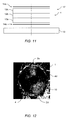
- Figure 11 shows the stack 17 of homogeneously with resin impregnated textile layers of Figure 9 , which is used to create the wet laminate repair patch 4 of Figure 10 .
- Figure 11 further illustrates the stacked pre-cut fiber fabric layers 12a, 12b, 12c that are arranged in-between the PTFE foils 14a, 14b.
- the stack 17 of homogeneously with resin impregnated textile layers is preferably squeezed prior to application to the inappropriate countersink 2a of Figure 2 .
- Figure 12 shows the wet laminate repair patch 4 of Figure 10 , which is illustratively fixed in the inappropriate countersink 2a of Figure 2 of the composite component 1 of Figure 2 by means of curing.
- Figure 12 further illustrates the excessive repair patch portions 4d of Figure 4 in the area 2d that surrounds the inappropriate countersink 2a.
Landscapes
- Engineering & Computer Science (AREA)
- Mechanical Engineering (AREA)
- Physics & Mathematics (AREA)
- Fluid Mechanics (AREA)
Abstract
Description
- The invention is related to a method of correcting, in a composite component, an inappropriate countersink with an inappropriate maximum diameter and/or depth, the inappropriate countersink being provided in the composite component at a fixation opening having a first opening diameter, the method comprising the features of
claim 1. The invention is further related to a pressure tool for correcting, in a composite component, an inappropriate countersink with an inappropriate maximum diameter and/or depth, the pressure tool comprising the features ofclaim 15. - During assembly of composite components, usually multiple boreholes are drilled and provided with countersinks that are adapted for installation of countersunk fasteners. However, the countersinks are frequently inappropriately realized, i. e. with an inappropriate maximum diameter and/or depth. In other words, the countersinks are frequently too large-scaled and/or too deep.
- These too large-scaled and/or too deep countersinks generally lead to an undesired and significant effort required for determining a residual safety margin provided by the finally assembled composite components. This, in turn, frequently leads to inappropriate and over-dimensioned correcting, i. e. repairing processes with high effort and low effective repair results, which usually only represent a concession that must necessarily be issued. This concession generally consists in the acceptance that a corrected, i. e. repaired countersink does not exhibit an original structure strength of the assembled composite components.
- More specifically, for correcting, i. e. repairing an inappropriate countersink, current methods employ an indirect treatment of a corresponding affected area, which consists either in filling of a cavity defined by the inappropriate countersink by means of compound material, or in installing a repair patch on top of the inappropriate countersink. However, while the filling with compound material merely represents a cosmetic repair method, the installing of the repair patch requires additional design space in an area surrounding the inappropriate countersink. Nevertheless, both treatments are ineffective and unsatisfactory, as they can only provide for reduced bearing strength capabilities which are comparatively far below an original structure strength of the assembled composite components.
- The document
EP 2 927 508 A1 describes a method that consists in installing an additional dimpled washer respectively bushing in the inappropriate countersink. This additional dimpled washer respectively bushing exhibits on the one hand outer dimensions corresponding to those of the inappropriate countersink and on the other hand inner dimensions corresponding to a countersunk fastener that is originally provided for installation in the inappropriate countersink. However, this method does not contribute in repairing the inappropriate countersink, but merely allows using the inappropriate countersink with the originally provided countersunk fastener. Furthermore, this method is also ineffective and unsatisfactory, as is also only provides for reduced bearing strength capabilities which are comparatively far below an original structure strength of the assembled composite components. - It is, therefore, an object of the present invention to provide a new method of correcting, in a composite component, an inappropriate countersink with an inappropriate maximum diameter and/or depth, the method being adapted for factually repairing an inappropriate countersink in a composite component with reduced effort by providing a comparatively similar to original structure strength. It is a further object of the present invention to provide a pressure tool that is suitable for use with this new method.
- One object of the present invention is solved by a method of correcting, in a composite component, an inappropriate countersink with an inappropriate maximum diameter and/or depth with the features of
claim 1. - More specifically, according to the invention a method of correcting, in a composite component, an inappropriate countersink with an inappropriate maximum diameter and/or depth is provided. The inappropriate countersink is provided in the composite component at a fixation opening having a first opening diameter. The method comprises at least the steps of: Preparing a repair patch with a repair patch opening having a second opening diameter that is at most equal to the first opening diameter; Arranging the repair patch on the composite component in an area surrounding the inappropriate countersink, such that the repair patch opening and the fixation opening are at least approximately aligned; Pressing the repair patch at least partly into the inappropriate countersink by means of an associated pressure tool; and Fixing the repair patch in the inappropriate countersink.
- The inventive method is simple, efficient and comparatively low-cost and allows for directly correcting, i. e. factually repairing, inappropriate countersinks in a composite component. Advantageously, the inventive method can be applied to any helicopter composite structures, major airframes and all kind of non-structural composite components which have to be assembled by countersunk fasteners.
- According to one aspect, the inventive method is performed using a wet lay-up lamination process with bi-directional fabric and different laminating systems. Advantageously, this method requires comparatively few effort and is suitable for providing an at least essentially similar to original structure strength.
- According to a preferred embodiment, the method further comprises at least the steps of: Preparing a polytetrafluorethylene tape with a polytetrafluorethylene tape opening having a third opening diameter that corresponds at least approximately to the inappropriate maximum diameter of the inappropriate countersink; and Arranging the polytetrafluorethylene tape on the composite component in the area surrounding the inappropriate countersink, prior to arranging the repair patch on the composite component, such that the polytetrafluorethylene tape opening and the fixation opening are at least approximately aligned, wherein the polytetrafluorethylene tape is arranged between the repair patch and the composite component.
- According to a further preferred embodiment, the step of pressing the repair patch at least partly into the inappropriate countersink comprises at least the steps of: Positioning a conical extension of the pressure tool over the repair patch such that the conical extension is aligned with the inappropriate countersink, wherein the conical extension is provided with dimensions that correspond at least approximately to inverted appropriate countersink dimensions; and Pressing the pressure tool onto the repair patch such that the conical extension presses an inner portion of the repair patch into the inappropriate countersink.
- According to a further preferred embodiment, the method further comprises at least the step of attaching, in a releasable manner, the pressure tool to the composite component by means of an associated clamping unit.
- According to a further preferred embodiment, the associated clamping unit comprises at least one screw that traverses the pressure tool and the conical extension, the repair patch, the polytetrafluorethylene tape and the composite component.
- According to a further preferred embodiment, the step of attaching the pressure tool to the composite component comprises at least the steps of: If an opposite component that is to be mounted to the composite component is not already arranged on a surface of the composite component that is opposed to a surface where the repair patch is arranged, arranging the opposite component on the surface of the composite component that is opposed to the surface where the repair patch is arranged; and Fixing the associated clamping unit at the opposite component.
- According to a further preferred embodiment, the step of preparing the repair patch comprises preparing a wet laminate repair patch, wherein the step of fixing the repair patch in the inappropriate countersink comprises curing the wet laminate repair patch in the inappropriate countersink.
- According to a further preferred embodiment, the step of preparing the wet laminate repair patch comprises fabricating the wet laminate repair patch with a basically quasi isotropic layup.
- According to a further preferred embodiment, fabricating the wet laminate repair patch with the basically quasi isotropic layup comprises stacking of at least three pre-cut fiber fabric layers having 0°/90°, +/- 45° and 0°/90° fiber orientations.
- According to a further preferred embodiment, the method further comprises at least the step of removing any excessive repair patch portions from the composite component.
- According to a further preferred embodiment, the step of removing any excessive repair patch portions comprises grinding the composite component at least in the area surrounding the inappropriate countersink.
- According to a further preferred embodiment, the method further comprises at least the step of creating an appropriate countersink with appropriate countersink dimensions subsequent to removing any excessive repair patch portions from the composite component.
- According to a further preferred embodiment, the method further comprises at least the step of activating the inappropriate countersink prior to arranging the repair patch on the composite component.
- According to a further preferred embodiment, the step of preparing the repair patch comprises preparing the repair patch with a structure strength that corresponds at least approximately to an underlying structure strength of the composite component.
- The other object of the present invention is solved by a pressure tool for correcting, in a composite component, an inappropriate countersink with an inappropriate maximum diameter and/or depth. The pressure tool comprises a conical extension that is provided with dimensions that correspond at least approximately to inverted appropriate countersink dimensions.
- Preferred embodiments of the invention are outlined by way of example in the following description with reference to the attached drawings. In these attached drawings, identical or identically functioning components and elements are labeled with identical reference numbers and characters and are, consequently, only described once in the following description.
-
Figure 1 shows a sectional view of an exemplary composite component with an appropriate countersink, -
Figure 2 shows the exemplary composite component ofFigure 1 with an inappropriate countersink, -
Figure 3 to Figure 5 illustrate an exemplary method of correcting the inappropriate countersink ofFigure 2 , -
Figure 6 to Figure 11 illustrate an exemplary method of manufacturing a repair patch that is suitable for correcting the inappropriate countersink ofFigure 2 , and -
Figure 12 shows the inappropriate countersink ofFigure 2 that is corrected with a repair patch according to the present invention. -
Figure 1 shows acomposite component 1 with acountersink 1 a having amaximum diameter 1 b and/ordepth 1 c. By way of example, thecountersink 1a defines an appropriate countersink. It should be noted that the term "appropriate countersink" is used in the context of the present application to designate a countersink having an intended predetermined maximum diameter and/or depth and, thus, an appropriate maximum diameter and/or depth. - Illustratively, the
appropriate countersink 1 a extends into afixation opening 10, i. e. thefixation opening 10 is provided with theappropriate countersink 1a. The fixation opening 10 exemplarily comprises a fixation openingdiameter 1d. - The fixation opening 10 and the
appropriate countersink 1 a preferentially define a through hole in thecomposite component 1 and are preferably adapted for accommodating an associated countersunk fastener, such as e. g. a screw or a bolt. The latter is preferentially adapted for mounting thecomposite component 1 to anopposite component 5 having afastener reception opening 5a that also comprises thefixation opening diameter 1d, similar to thefixation opening 10 provided in thecomposite component 1. The fastener reception opening 5a preferably defines a through hole in theopposite component 5. - Preferably, the
opposite component 5 is embodied as a composite component similar to thecomposite component 1. However, theopposite component 5 is not limited to composite components and an arbitrarily selected other material can be used for implementing theopposite component 5. -
Figure 2 shows thecomposite component 1 with acountersink 2a having amaximum diameter 2b and/ordepth 2c. By way of example, thecountersink 2a defines an inappropriate countersink. Theinappropriate countersink 2a also extends into the fixation opening 10 with thefixation opening diameter 1d ofFigure 1 . The fixation opening 10 and theinappropriate countersink 2a preferentially define a through hole in thecomposite component 1. As described above with reference toFigure 1 , thecomposite component 1 is again adapted for being mounted to theopposite component 5 having the fastener reception opening 5a that also comprises thefixation opening diameter 1d, similar to thefixation opening 10 provided in thecomposite component 1. - It should be noted that the term "inappropriate countersink" is used in the context of the present application to designate a countersink having an excessive, i. e. too large maximum diameter and/or depth compared to an intended predetermined maximum diameter and/or depth and, thus, an inappropriate maximum diameter and/or depth. Illustratively, the
inappropriate countersink 2a comprises an inappropriatemaximum diameter 2b as it is greater than the appropriatemaximum diameter 1b ofFigure 1 , and theinappropriate countersink 2a comprises an inappropriatemaximum depth 2c as it is deeper than the appropriatemaximum depth 1c ofFigure 1 . -
Figure 3 illustrates initial, preparatory steps of a method of correcting, in thecomposite component 1 ofFigure 2 , theinappropriate countersink 2a with the inappropriatemaximum diameter 2b and/ordepth 2c. This method aims to modify theinappropriate countersink 2a structurally into theappropriate countersink 1 a ofFigure 1 prior to mounting thecomposite component 1 to theopposite component 5. - According to one aspect, initially a
tape 3 with atape opening 3a having an associatedopening diameter 3b is prepared. The associatedopening diameter 3b preferably corresponds at least approximately to the inappropriatemaximum diameter 2b of theinappropriate countersink 2a and is, preferentially, at least not smaller than the inappropriatemaximum diameter 2b. Thetape 3 is preferably a polytetrafluorethylene (PTFE) tape. - Furthermore, a
repair patch 4 with arepair patch opening 4a having a repairpatch opening diameter 4c is prepared as described in detail below with reference toFigure 7 to Figure 10 . Therepair patch 4 is preferably prepared with a structure strength that corresponds at least approximately to an underlying structure strength of thecomposite component 1. The repairpatch opening diameter 4c is preferably at most equal to thefixation opening diameter 1d of thefixation opening 10 ofFigure 1 , preferentially at least within conventional predetermined manufacturing tolerances. - According to one aspect, the
PTFE tape 3 and therepair patch 4 are prepared and manufactured separately. This can be done simultaneously, or completely independent of each other. - The
PTFE tape 3 is then arranged on thecomposite component 1 in anarea 2d surrounding theinappropriate countersink 2a, such that thetape opening 3a and thefixation opening 10 are at least approximately aligned and, preferably, coaxially arranged. Furthermore, therepair patch 4 is arranged on thecomposite component 1 in thearea 2d surrounding theinappropriate countersink 2a, such that therepair patch opening 4a and thefixation opening 10 are at least approximately aligned and, preferably, coaxially arranged. - According to one aspect, the
PTFE tape 3 is arranged in thearea 2d on thecomposite component 1 prior to arranging therepair patch 4 on thecomposite component 1. This is preferably done for surface protection of thearea 2d. In other words, thePTFE tape 3 is preferably arranged on thecomposite component 1 in thearea 2d surrounding theinappropriate countersink 2a such that thePTFE tape 3 is arranged between therepair patch 4 and thecomposite component 1. - Preferably, the
inappropriate countersink 2a is activated, e. g. by hand using sandpaper, and then cleaned prior to arranging therepair patch 4 on thecomposite component 1, i. e. on thePTFE tape 3. This activation and cleaning can also be performed prior to arranging thePTFE tape 3 on thecomposite component 1. However, it should be noted that such an activation and cleaning is a well-known process that is preferably performed according to respectively valid and applicable activating and cleaning standards and, therefore, not described in detail for brevity and conciseness. - Then, a
pressure tool 6 and, more specifically, aconical extension 6a of thepressure tool 6 is positioned over therepair patch 4, i. e. illustratively above thecomposite component 1, such that theconical extension 6a is aligned, preferably coaxially arranged, with theinappropriate countersink 2a. Theconical extension 6a preferentially comprises dimensions that correspond at least approximately to inverted appropriate countersink dimensions, i. e. to respective dimensions of theappropriate countersink 1 a ofFigure 1 . - Preferably, the
pressure tool 6 further comprises atool opening 6b, which preferentially defines a through hole through thepressure tool 6 and itsconical extension 6a. Thetool opening 6b is preferably embodied for enabling accommodation of an associated clamping unit (7 inFigure 4 ). -
Figure 4 illustrates additional steps of the method of correcting, in thecomposite component 1 ofFigure 2 , theinappropriate countersink 2a with the inappropriatemaximum diameter 2b and/ordepth 2c. These additional steps are preferably performed after the initial, preparatory steps described above with reference toFigure 3 , according to which thePTFE tape 3, therepair patch 4 and thepressure tool 6 were arranged on thecomposite component 1, which should subsequently be mounted to theopposite component 5 ofFigure 3 . - In this respect, it should be noted that the
opposite component 5 is illustrated inFigure 1 to Figure 4 as being arranged on a surface of thecomposite component 1 that is opposed to a surface where therepair patch 4 is arranged. If, however, theopposite component 5 that is to be mounted to thecomposite component 1 is not already arranged on this surface of thecomposite component 1 that is opposed to the surface where therepair patch 4 is arranged, theopposite component 5 is arranged on this surface of thecomposite component 1 that is opposed to the surface where therepair patch 4 is arranged, prior to continuing the additional steps of the method of correcting theinappropriate countersink 2a. - According to one aspect, pressure is applied to the
pressure tool 6 and, thus, onto therepair patch 4, such that therepair patch 4 is at least partly pressed into theinappropriate countersink 2a. More specifically, by applying pressure to thepressure tool 6, theconical extension 6a of thepressure tool 6 presses an inner portion of therepair patch 4 into theinappropriate countersink 2a, i. e. against aninner area 4b of theinappropriate countersink 2a. - In order to maintain a given pressure on the
pressure tool 6, the latter is attached, preferably in a releasable manner, to thecomposite component 1, and preferentially also to theopposite component 5, by means of an associatedclamping unit 7. The latter is preferably fixed at theopposite component 5, as described below. - According to one aspect, the associated
clamping unit 7 comprises at least one screw or bolt that traverses thepressure tool 6 and itsconical extension 6a, therepair patch 4, thePTFE tape 3 and thecomposite component 1. More specifically, the at least one screw orbolt 7 is retained in thetool opening 6b, thefixation opening 10 and thefastener reception opening 5a by means of an associatednut 9 and exhibits a screw or boltdiameter 7a that amounts at most to thefixation opening diameter 1d of thefixation opening 10. Preferably, thenut 9 pushes awasher 8 against theopposite component 5. - It should be noted that the
repair patch 4 should preferentially only be pressed softly into theinappropriate countersink 2a in order to avoid an undesired, too strong squeezing thereof. Therefore, thenut 9 is preferably only tightened by hand without use of any additional tightening tool. - Finally, the
repair patch 4 is fixed in theinappropriate countersink 2a. This is preferably performed by means of curing, which is a well-known process and, therefore, not described in detail for brevity and conciseness. Preferentially, the curing is performed in room temperature condition or under heat without vacuum, during at least 24 hours and in clamped condition, i. e. by applying mechanical pressure by means of the associatedclamping unit 7. - It should be noted that after this curing, the
repair patch 4 still comprises an outer region that is arranged on thePTFE tape 3 and that defines excessiverepair patch portions 4d that are not required for correcting, i. e. repairing theinappropriate countersink 2a. Consequently, these excessiverepair patch portions 4d can be removed subsequently, as described hereinafter with reference toFigure 5 . -
Figure 5 shows thecomposite component 1 and theopposite component 5 ofFigure 4 after removal of thepressure tool 6, the at least one screw orbolt 7, thenut 9 and thewasher 8.Figure 5 further illustrates a final step of the method of correcting, in thecomposite component 1 ofFigure 2 , theinappropriate countersink 2a with the inappropriatemaximum diameter 2b and/ordepth 2c. - This final step is preferably performed after the additional steps described above with reference to
Figure 4 and consists in removing at least the excessiverepair patch portions 4d ofFigure 4 and, preferentially, also thePTFE tape 3 from thecomposite component 1. Removing at least the excessiverepair patch portions 4d preferably comprises grinding thecomposite component 1 at least in thearea 2d surrounding theinappropriate countersink 2a. ThePTFE tape 3 can be removed in the same manner. - Preferably, the final step should be performed in order to restore an original surface condition. In other words, the surface of the
composite component 1 should have the same quality after having corrected, i. e. repaired theinappropriate countersink 2a, as before. - According to one aspect, if required, an appropriate countersink with appropriate countersink dimensions can be created at the location of the
inappropriate countersink 2a. This is preferably performed subsequent to removing any excessiverepair patch portions 4d from thecomposite component 1. -
Figure 6 shows therepair patch 4 ofFigure 3 to Figure 5 for illustrating an exemplary layup. Preferably, therepair patch 4 is embodied as a laminating system that is based on a pre-cut fiber-reinforced textile fabric and, preferentially, mixed according to respectively valid and applicable standards, which are well-known to the person skilled in the art and, therefore, not explained in greater detail, for brevity and conciseness. - According to one aspect, a certain size of the fiber-reinforced textile fabric, preferably a carbon fiber textile fabric, is cut out depending on the
inappropriate diameter 2b anddepth 2c of the inappropriate countersink ofFigure 2 . On the basis of this cutout carbon fiber textile fabric, preferably impregnated, i. e. wet patch plies and, more specifically, wet laminate patch plies can be created as described below with reference toFigure 7 andFigure 8 , wherefrom therepair patch 4 can be extracted by cutting or using a hollow punch as described below with reference toFigure 9 . In other words, therepair patch 4 is preferably prepared as a wet laminate repair patch and, therefore, also referred to as the "wetlaminate repair patch 4" hereinafter. - According to one aspect, the layup of the wet
laminate repair patch 4 is preferentially basically quasi isotropic and comprises at least three pre-cutfiber fabric layers fiber orientations fiber fabric layers composite component 1 of the preceding figures, or a basic coordinate system of an underlying structure, wherein the wetlaminate repair patch 4 should be used. -
Figure 7 andFigure 8 illustrate steps of a method of fabricating the wetlaminate repair patch 4 ofFigure 3 to Figure 5 with a basically quasi isotropic layup, as mentioned above with reference toFigure 6 . The method preferably starts according toFigure 7 by arranging thePTFE foil 14a on asuitable fabrication support 13, i. e. a workbench. If applicable, thePTFE foil 14a can be wetted with a thin resin film. - Then, a pre-cut fiber fabric layer, e. g. the pre-cut
fiber fabric layer 12a ofFigure 6 , is applied, i. e. positioned on the wettedPTFE foil 14a. Subsequently, aresin 15 is applied to, e. g. spilled on, the pre-cutfiber fabric layer 12a such that a preferred fabric to resin ratio of 50/50 ppw is preferably obtained. - The
resin 15 is preferably equally distributed into the pre-cutfiber fabric layer 12a by means of a suitable tool (e. g. spatula 16 inFigure 8 ), in order to remove enclosed air. Then, aPTFE foil 14b is applied onto the wetted pre-cutfiber fabric layer 12a and the suitable tool is preferentially cleaned. - As illustrated in
Figure 8 , the suitable tool, which is exemplarily illustrated as aspatula 16, is then applied to thePTFE foil 14b that covers the wetted pre-cutfiber fabric layer 12a. Preferably, thespatula 16 is moved from a middle position straight outwards with slight pressure in order to squeeze out entrapped air andexcessive resin 15. This is preferentially performed until the pre-cutfiber fabric layer 12a is homogenously impregnated with theresin 15. - It should be noted that the
spatula 16 is merely illustrated by way of example and not for limiting the present invention accordingly. Instead, other suitable tools may likewise be used, such as e. g. a roller. - According to one aspect, the method steps that are described above with reference to
Figure 7 andFigure 8 are repeated for the pre-cutfiber fabric layers resin 15 and covered by the PTFE foils 14a, 14b. As a result, all of the pre-cutfiber fabric layers resin 15. -
Figure 9 shows astack 17 of homogeneously with resin impregnated textile layers comprising the stacked pre-cutfiber fabric layers Figure 6 to Figure 8 . By way of example, thestack 17 of homogeneously with resin impregnated textile layers is created by removing thePTFE foil 14b from the impregnatedfiber fabric layer 12a as well as thePTFE foil 14a from the impregnatedfiber fabric layer 12b, and positioning the impregnatedfiber fabric layer 12b on the impregnatedfiber fabric layer 12a. Then, entrapped air and excessive resin can be squeezed out as described above. Subsequently, thePTFE foil 14b is removed from the impregnatedfiber fabric layer 12b as well as thePTFE foil 14a from the impregnatedfiber fabric layer 12c, and the impregnatedfiber fabric layer 12c is positioned on the impregnatedfiber fabric layer 12b. Subsequently, entrapped air and excessive resin can again be squeezed out as described above. - According to one aspect, the wet
laminate repair patch 4 ofFigure 3 to Figure 6 can then be cut out from thestack 17 of homogeneously with resin impregnated textile layers. Illustratively, this is performed by means of ahollow punch 18. -
Figure 10 shows the wetlaminate repair patch 4 ofFigure 9 . The latter is illustratively provided with the repair patch opening 4a ofFigure 3 , e. g. by means of cutting, punching or drilling. -
Figure 11 shows thestack 17 of homogeneously with resin impregnated textile layers ofFigure 9 , which is used to create the wetlaminate repair patch 4 ofFigure 10 .Figure 11 further illustrates the stacked pre-cutfiber fabric layers stack 17 of homogeneously with resin impregnated textile layers is preferably squeezed prior to application to theinappropriate countersink 2a ofFigure 2 . -
Figure 12 shows the wetlaminate repair patch 4 ofFigure 10 , which is illustratively fixed in theinappropriate countersink 2a ofFigure 2 of thecomposite component 1 ofFigure 2 by means of curing.Figure 12 further illustrates the excessiverepair patch portions 4d ofFigure 4 in thearea 2d that surrounds theinappropriate countersink 2a. -
- 1
- composite component
- 1a
- appropriate countersink
- 1b
- appropriate diameter
- 1c
- appropriate depth
- 1d
- fixation opening diameter
- 2a
- inappropriate countersink
- 2b
- inappropriate diameter
- 2c
- inappropriate depth
- 2d
- countersink surrounding area
- 3
- PTFE tape
- 3a
- PTFE tape opening
- 3b
- PTFE tape opening diameter
- 4
- repair patch
- 4a
- repair patch opening
- 4b
- countersink inner area
- 4c
- repair patch opening diameter
- 4d
- excessive repair patch portions
- 5
- opposite component
- 5a
- opposite component opening
- 6
- pressure tool
- 6a
- conical extension
- 6b
- pressure tool opening
- 7
- pressure application screw
- 7a
- screw diameter
- 8
- washer
- 9
- nut
- 10
- fixation opening
- 11a, 11b, 11c
- fiber orientations
- 12a, 12b, 12c
- pre-cut fiber layers
- 13
- repair patch fabrication support
- 14a, 14b
- PTFE foils
- 15
- resin
- 16
- spatula
- 17
- homogeneously with resin impregnated textile layers
- 18
- hollow punch
Claims (15)
- A method of correcting, in a composite component (1), an inappropriate countersink (2a) with an inappropriate maximum diameter (2b) and/or depth (2c), the inappropriate countersink (2a) being provided in the composite component (1) at a fixation opening (10) having a first opening diameter (1d), the method comprising at least the steps of:- Preparing a repair patch (4) with a repair patch opening (4a) having a second opening diameter (4c) that is at most equal to the first opening diameter (1d);- Arranging the repair patch (4) on the composite component (1) in an area (2d) surrounding the inappropriate countersink (2a), such that the repair patch opening (4a) and the fixation opening (10) are at least approximately aligned;- Pressing the repair patch (4) at least partly into the inappropriate countersink (2a) by means of an associated pressure tool (6); and- Fixing the repair patch (4) in the inappropriate countersink (2a).
- The method according to claim 1,
characterized by further comprising at least the steps of:- Preparing a polytetrafluorethylene tape (3) with a polytetrafluorethylene tape opening (3a) having a third opening diameter (3b) that corresponds at least approximately to the inappropriate maximum diameter (2b) of the inappropriate countersink (2a); and- Arranging the polytetrafluorethylene tape (3) on the composite component (1) in the area (2d) surrounding the inappropriate countersink (2a), prior to arranging the repair patch (4) on the composite component (1), such that the polytetrafluorethylene tape opening (3a) and the fixation opening (10) are at least approximately aligned, wherein the polytetrafluorethylene tape (3) is arranged between the repair patch (4) and the composite component (1). - The method according to claim 2,
characterized in that the step of pressing the repair patch (4) at least partly into the inappropriate countersink (2a) comprises at least the steps of:- Positioning a conical extension (6a) of the pressure tool (6) over the repair patch (4) such that the conical extension (6a) is aligned with the inappropriate countersink (2a), wherein the conical extension (6a) is provided with dimensions that correspond at least approximately to inverted appropriate countersink dimensions (1 b, 1 c); and- Pressing the pressure tool (6) onto the repair patch (4) such that the conical extension (6a) presses an inner portion of the repair patch (4) into the inappropriate countersink (2a). - The method according to claim 3,
characterized by further comprising at least the step of attaching, in a releasable manner, the pressure tool (6) to the composite component (1) by means of an associated clamping unit (7). - The method according to claim 4,
characterized in that the associated clamping unit (7) comprises at least one screw (7) that traverses the pressure tool (6) and the conical extension (6a), the repair patch (4), the polytetrafluorethylene tape (3) and the composite component (1). - The method according to claim 4,
characterized in that the step of attaching the pressure tool (6) to the composite component (1) comprises at least the steps of:- If an opposite component (5) that is to be mounted to the composite component (1) is not already arranged on a surface of the composite component (1) that is opposed to a surface where the repair patch (4) is arranged, arranging the opposite component (5) on the surface of the composite component (1) that is opposed to the surface where the repair patch (4) is arranged; and- Fixing the associated clamping unit (7) at the opposite component (5). - The method according to claim 1,
characterized in that the step of preparing the repair patch (4) comprises preparing a wet laminate repair patch (4), wherein the step of fixing the repair patch (4) in the inappropriate countersink (2a) comprises curing the wet laminate repair patch (4) in the inappropriate countersink (2a). - The method according to claim 7,
characterized in that the step of preparing the wet laminate repair patch (4) comprises fabricating the wet laminate repair patch (4) with a basically quasi isotropic layup. - The method according to claim 8,
characterized in that fabricating the wet laminate repair patch (4) with the basically quasi isotropic layup comprises stacking of at least three pre-cut fiber fabric layers having 0°/90°, +/- 45° and 0°/90° fiber orientations. - The method according to claim 1,
characterized by further comprising at least the step of removing any excessive repair patch portions (4d) from the composite component (1). - The method according to claim 10,
characterized in that the step of removing any excessive repair patch portions (4d) comprises grinding the composite component (1) at least in the area (2d) surrounding the inappropriate countersink (2a). - The method according to claim 10,
characterized by further comprising at least the step of creating an appropriate countersink (1 a) with appropriate countersink dimensions (1 b, 1 c) subsequent to removing any excessive repair patch portions (4d) from the composite component (1). - The method according to claim 1,
characterized by further comprising at least the step of activating the inappropriate countersink (2a) prior to arranging the repair patch (4) on the composite component (1). - The method according to claim 1,
characterized in that the step of preparing the repair patch (4) comprises preparing the repair patch (4) with a structure strength that corresponds at least approximately to an underlying structure strength of the composite component (1). - A pressure tool (6) for correcting, in a composite component (1), an inappropriate countersink (2a) with an inappropriate maximum diameter (2b) and/or depth (2c), the pressure tool (6) comprising a conical extension (6a) that is provided with dimensions that correspond at least approximately to inverted appropriate countersink dimensions (1b, 1c).
Priority Applications (2)
| Application Number | Priority Date | Filing Date | Title |
|---|---|---|---|
| EP16400018.4A EP3248768B1 (en) | 2016-05-26 | 2016-05-26 | A method of correcting an inappropriate countersink in a composite component |
| US15/606,482 US10695995B2 (en) | 2016-05-26 | 2017-05-26 | Method of correcting an inappropriate countersink in a composite component |
Applications Claiming Priority (1)
| Application Number | Priority Date | Filing Date | Title |
|---|---|---|---|
| EP16400018.4A EP3248768B1 (en) | 2016-05-26 | 2016-05-26 | A method of correcting an inappropriate countersink in a composite component |
Publications (2)
| Publication Number | Publication Date |
|---|---|
| EP3248768A1 true EP3248768A1 (en) | 2017-11-29 |
| EP3248768B1 EP3248768B1 (en) | 2018-10-03 |
Family
ID=56263644
Family Applications (1)
| Application Number | Title | Priority Date | Filing Date |
|---|---|---|---|
| EP16400018.4A Active EP3248768B1 (en) | 2016-05-26 | 2016-05-26 | A method of correcting an inappropriate countersink in a composite component |
Country Status (2)
| Country | Link |
|---|---|
| US (1) | US10695995B2 (en) |
| EP (1) | EP3248768B1 (en) |
Cited By (1)
| Publication number | Priority date | Publication date | Assignee | Title |
|---|---|---|---|---|
| DE102019107202A1 (en) * | 2019-03-20 | 2020-09-24 | Airbus Operations Gmbh | Processing method, application tool and processing arrangement for changing or repairing a surface location of a workpiece surface of a fiber composite workpiece |
Families Citing this family (2)
| Publication number | Priority date | Publication date | Assignee | Title |
|---|---|---|---|---|
| EP3281861B1 (en) * | 2016-08-11 | 2019-10-02 | AIRBUS HELICOPTERS DEUTSCHLAND GmbH | A rotary wing aircraft with a fuselage that comprises at least one structural stiffened panel |
| US12151445B2 (en) * | 2022-09-28 | 2024-11-26 | The Boeing Company | Countersinks in thin gauge thermoplastic skins |
Citations (8)
| Publication number | Priority date | Publication date | Assignee | Title |
|---|---|---|---|---|
| US5059059A (en) * | 1989-05-05 | 1991-10-22 | Mcdonnell Douglas Corporation | Conical expansion washer |
| DE19856395A1 (en) * | 1998-12-07 | 2000-06-08 | Nuovakautschuk Gmbh | Boring or milling tool for repairing tire damage extending between inner and outer surfaces has non-cutting, two part tip to avoid damaging tire structure |
| US20070177330A1 (en) * | 2005-09-06 | 2007-08-02 | Ackerman Patrice K | Copper grid repair technique for lightning strike protection |
| EP2517865A1 (en) * | 2011-04-28 | 2012-10-31 | United Technologies Corporation | Replacing an aperture in a laminated component |
| US20140141190A1 (en) * | 2012-11-20 | 2014-05-22 | Mitsubishi Aircraft Corporation | Method of repairing composite material and composite material |
| US20140298956A1 (en) * | 2012-05-23 | 2014-10-09 | U.S. Thermoelectric Consortium | Tire repair kit |
| WO2015026798A1 (en) * | 2013-08-20 | 2015-02-26 | United Technologies Corporation | Replacing an aperture with an annular bushing in a composite laminated composite component |
| EP2927508A1 (en) | 2014-04-02 | 2015-10-07 | The Boeing Company | Rework system for composite structures |
-
2016
- 2016-05-26 EP EP16400018.4A patent/EP3248768B1/en active Active
-
2017
- 2017-05-26 US US15/606,482 patent/US10695995B2/en not_active Expired - Fee Related
Patent Citations (8)
| Publication number | Priority date | Publication date | Assignee | Title |
|---|---|---|---|---|
| US5059059A (en) * | 1989-05-05 | 1991-10-22 | Mcdonnell Douglas Corporation | Conical expansion washer |
| DE19856395A1 (en) * | 1998-12-07 | 2000-06-08 | Nuovakautschuk Gmbh | Boring or milling tool for repairing tire damage extending between inner and outer surfaces has non-cutting, two part tip to avoid damaging tire structure |
| US20070177330A1 (en) * | 2005-09-06 | 2007-08-02 | Ackerman Patrice K | Copper grid repair technique for lightning strike protection |
| EP2517865A1 (en) * | 2011-04-28 | 2012-10-31 | United Technologies Corporation | Replacing an aperture in a laminated component |
| US20140298956A1 (en) * | 2012-05-23 | 2014-10-09 | U.S. Thermoelectric Consortium | Tire repair kit |
| US20140141190A1 (en) * | 2012-11-20 | 2014-05-22 | Mitsubishi Aircraft Corporation | Method of repairing composite material and composite material |
| WO2015026798A1 (en) * | 2013-08-20 | 2015-02-26 | United Technologies Corporation | Replacing an aperture with an annular bushing in a composite laminated composite component |
| EP2927508A1 (en) | 2014-04-02 | 2015-10-07 | The Boeing Company | Rework system for composite structures |
Cited By (2)
| Publication number | Priority date | Publication date | Assignee | Title |
|---|---|---|---|---|
| DE102019107202A1 (en) * | 2019-03-20 | 2020-09-24 | Airbus Operations Gmbh | Processing method, application tool and processing arrangement for changing or repairing a surface location of a workpiece surface of a fiber composite workpiece |
| US11559959B2 (en) | 2019-03-20 | 2023-01-24 | Airbus Operations Gmbh | Machining method, application tool, and machining arrangement for modifying or repairing a surface spot of a workpiece surface of a fiber composite workpiece |
Also Published As
| Publication number | Publication date |
|---|---|
| US10695995B2 (en) | 2020-06-30 |
| EP3248768B1 (en) | 2018-10-03 |
| US20170341322A1 (en) | 2017-11-30 |
Similar Documents
| Publication | Publication Date | Title |
|---|---|---|
| US10695995B2 (en) | Method of correcting an inappropriate countersink in a composite component | |
| EP2927508B1 (en) | Rework system for composite structures | |
| EP3116705B1 (en) | Method for connecting components one of which is made of a fiber-reinforced plastic material | |
| US10160169B1 (en) | Systems and methods of forming a composite layup structure | |
| DE102007026099A1 (en) | Apparatus and method for processing a fiber composite structure | |
| US10322563B2 (en) | Panel-insert assembly and method | |
| EP2274158A1 (en) | Method and shaping device for producing a composite fibre component for air and space travel | |
| CA2908558A1 (en) | Lightweight support structure, method of producing a lightweight support structure, composite sandwich panel and method of producing a composite sandwich panel | |
| KR20080007432A (en) | Single vacuum debulk composite panel repair | |
| EP2561943B1 (en) | Drilling tool and method of drilling | |
| EP2930011A1 (en) | A method of repairing a sandwich component having a honeycomb core with an associated core height | |
| JP2010000750A (en) | Screw hole sealing structure | |
| EP3124221A1 (en) | Composite structure | |
| JP6204093B2 (en) | Method for manufacturing reinforcing structure | |
| JP2001030997A (en) | Composite wing and method of manufacturing the same | |
| EP2428352A1 (en) | Vacuum assembly for pressurising a component during its production and method for producing a component | |
| US20060011294A1 (en) | Method for production of a laminate from metal layers and fibre reinforced plastic layers | |
| US10773507B2 (en) | Method for the preparation of a semifinished product made of fiber material prior to a wet-pressing process | |
| US10688731B2 (en) | System and method for bonding structural components | |
| WO2018114145A2 (en) | Fastening insert for a component made of plastic, foam or composite material | |
| US10166724B2 (en) | Method for providing spacers | |
| CN111075810A (en) | Method and system for connecting two components | |
| JP6685752B2 (en) | Laminated plate and method of processing laminated plate | |
| CN105882105A (en) | Method of making peelable wedges | |
| DE102015013233B4 (en) | Method for producing a component composite |
Legal Events
| Date | Code | Title | Description |
|---|---|---|---|
| PUAI | Public reference made under article 153(3) epc to a published international application that has entered the european phase |
Free format text: ORIGINAL CODE: 0009012 |
|
| STAA | Information on the status of an ep patent application or granted ep patent |
Free format text: STATUS: THE APPLICATION HAS BEEN PUBLISHED |
|
| STAA | Information on the status of an ep patent application or granted ep patent |
Free format text: STATUS: REQUEST FOR EXAMINATION WAS MADE |
|
| AK | Designated contracting states |
Kind code of ref document: A1 Designated state(s): AL AT BE BG CH CY CZ DE DK EE ES FI FR GB GR HR HU IE IS IT LI LT LU LV MC MK MT NL NO PL PT RO RS SE SI SK SM TR |
|
| AX | Request for extension of the european patent |
Extension state: BA ME |
|
| 17P | Request for examination filed |
Effective date: 20171107 |
|
| RBV | Designated contracting states (corrected) |
Designated state(s): AL AT BE BG CH CY CZ DE DK EE ES FI FR GB GR HR HU IE IS IT LI LT LU LV MC MK MT NL NO PL PT RO RS SE SI SK SM TR |
|
| GRAP | Despatch of communication of intention to grant a patent |
Free format text: ORIGINAL CODE: EPIDOSNIGR1 |
|
| STAA | Information on the status of an ep patent application or granted ep patent |
Free format text: STATUS: GRANT OF PATENT IS INTENDED |
|
| INTG | Intention to grant announced |
Effective date: 20180322 |
|
| GRAS | Grant fee paid |
Free format text: ORIGINAL CODE: EPIDOSNIGR3 |
|
| GRAA | (expected) grant |
Free format text: ORIGINAL CODE: 0009210 |
|
| STAA | Information on the status of an ep patent application or granted ep patent |
Free format text: STATUS: THE PATENT HAS BEEN GRANTED |
|
| AK | Designated contracting states |
Kind code of ref document: B1 Designated state(s): AL AT BE BG CH CY CZ DE DK EE ES FI FR GB GR HR HU IE IS IT LI LT LU LV MC MK MT NL NO PL PT RO RS SE SI SK SM TR |
|
| REG | Reference to a national code |
Ref country code: GB Ref legal event code: FG4D |
|
| REG | Reference to a national code |
Ref country code: CH Ref legal event code: EP Ref country code: AT Ref legal event code: REF Ref document number: 1048152 Country of ref document: AT Kind code of ref document: T Effective date: 20181015 |
|
| REG | Reference to a national code |
Ref country code: IE Ref legal event code: FG4D Ref country code: DE Ref legal event code: R096 Ref document number: 602016006230 Country of ref document: DE |
|
| REG | Reference to a national code |
Ref country code: NL Ref legal event code: MP Effective date: 20181003 |
|
| REG | Reference to a national code |
Ref country code: LT Ref legal event code: MG4D |
|
| REG | Reference to a national code |
Ref country code: AT Ref legal event code: MK05 Ref document number: 1048152 Country of ref document: AT Kind code of ref document: T Effective date: 20181003 |
|
| PG25 | Lapsed in a contracting state [announced via postgrant information from national office to epo] |
Ref country code: NL Free format text: LAPSE BECAUSE OF FAILURE TO SUBMIT A TRANSLATION OF THE DESCRIPTION OR TO PAY THE FEE WITHIN THE PRESCRIBED TIME-LIMIT Effective date: 20181003 |
|
| PG25 | Lapsed in a contracting state [announced via postgrant information from national office to epo] |
Ref country code: FI Free format text: LAPSE BECAUSE OF FAILURE TO SUBMIT A TRANSLATION OF THE DESCRIPTION OR TO PAY THE FEE WITHIN THE PRESCRIBED TIME-LIMIT Effective date: 20181003 Ref country code: PL Free format text: LAPSE BECAUSE OF FAILURE TO SUBMIT A TRANSLATION OF THE DESCRIPTION OR TO PAY THE FEE WITHIN THE PRESCRIBED TIME-LIMIT Effective date: 20181003 Ref country code: BG Free format text: LAPSE BECAUSE OF FAILURE TO SUBMIT A TRANSLATION OF THE DESCRIPTION OR TO PAY THE FEE WITHIN THE PRESCRIBED TIME-LIMIT Effective date: 20190103 Ref country code: CZ Free format text: LAPSE BECAUSE OF FAILURE TO SUBMIT A TRANSLATION OF THE DESCRIPTION OR TO PAY THE FEE WITHIN THE PRESCRIBED TIME-LIMIT Effective date: 20181003 Ref country code: LT Free format text: LAPSE BECAUSE OF FAILURE TO SUBMIT A TRANSLATION OF THE DESCRIPTION OR TO PAY THE FEE WITHIN THE PRESCRIBED TIME-LIMIT Effective date: 20181003 Ref country code: AT Free format text: LAPSE BECAUSE OF FAILURE TO SUBMIT A TRANSLATION OF THE DESCRIPTION OR TO PAY THE FEE WITHIN THE PRESCRIBED TIME-LIMIT Effective date: 20181003 Ref country code: NO Free format text: LAPSE BECAUSE OF FAILURE TO SUBMIT A TRANSLATION OF THE DESCRIPTION OR TO PAY THE FEE WITHIN THE PRESCRIBED TIME-LIMIT Effective date: 20190103 Ref country code: IS Free format text: LAPSE BECAUSE OF FAILURE TO SUBMIT A TRANSLATION OF THE DESCRIPTION OR TO PAY THE FEE WITHIN THE PRESCRIBED TIME-LIMIT Effective date: 20190203 Ref country code: ES Free format text: LAPSE BECAUSE OF FAILURE TO SUBMIT A TRANSLATION OF THE DESCRIPTION OR TO PAY THE FEE WITHIN THE PRESCRIBED TIME-LIMIT Effective date: 20181003 Ref country code: HR Free format text: LAPSE BECAUSE OF FAILURE TO SUBMIT A TRANSLATION OF THE DESCRIPTION OR TO PAY THE FEE WITHIN THE PRESCRIBED TIME-LIMIT Effective date: 20181003 Ref country code: LV Free format text: LAPSE BECAUSE OF FAILURE TO SUBMIT A TRANSLATION OF THE DESCRIPTION OR TO PAY THE FEE WITHIN THE PRESCRIBED TIME-LIMIT Effective date: 20181003 |
|
| PG25 | Lapsed in a contracting state [announced via postgrant information from national office to epo] |
Ref country code: AL Free format text: LAPSE BECAUSE OF FAILURE TO SUBMIT A TRANSLATION OF THE DESCRIPTION OR TO PAY THE FEE WITHIN THE PRESCRIBED TIME-LIMIT Effective date: 20181003 Ref country code: SE Free format text: LAPSE BECAUSE OF FAILURE TO SUBMIT A TRANSLATION OF THE DESCRIPTION OR TO PAY THE FEE WITHIN THE PRESCRIBED TIME-LIMIT Effective date: 20181003 Ref country code: RS Free format text: LAPSE BECAUSE OF FAILURE TO SUBMIT A TRANSLATION OF THE DESCRIPTION OR TO PAY THE FEE WITHIN THE PRESCRIBED TIME-LIMIT Effective date: 20181003 Ref country code: PT Free format text: LAPSE BECAUSE OF FAILURE TO SUBMIT A TRANSLATION OF THE DESCRIPTION OR TO PAY THE FEE WITHIN THE PRESCRIBED TIME-LIMIT Effective date: 20190203 Ref country code: GR Free format text: LAPSE BECAUSE OF FAILURE TO SUBMIT A TRANSLATION OF THE DESCRIPTION OR TO PAY THE FEE WITHIN THE PRESCRIBED TIME-LIMIT Effective date: 20190104 |
|
| REG | Reference to a national code |
Ref country code: DE Ref legal event code: R097 Ref document number: 602016006230 Country of ref document: DE |
|
| PG25 | Lapsed in a contracting state [announced via postgrant information from national office to epo] |
Ref country code: DK Free format text: LAPSE BECAUSE OF FAILURE TO SUBMIT A TRANSLATION OF THE DESCRIPTION OR TO PAY THE FEE WITHIN THE PRESCRIBED TIME-LIMIT Effective date: 20181003 |
|
| PLBE | No opposition filed within time limit |
Free format text: ORIGINAL CODE: 0009261 |
|
| STAA | Information on the status of an ep patent application or granted ep patent |
Free format text: STATUS: NO OPPOSITION FILED WITHIN TIME LIMIT |
|
| PG25 | Lapsed in a contracting state [announced via postgrant information from national office to epo] |
Ref country code: EE Free format text: LAPSE BECAUSE OF FAILURE TO SUBMIT A TRANSLATION OF THE DESCRIPTION OR TO PAY THE FEE WITHIN THE PRESCRIBED TIME-LIMIT Effective date: 20181003 Ref country code: SM Free format text: LAPSE BECAUSE OF FAILURE TO SUBMIT A TRANSLATION OF THE DESCRIPTION OR TO PAY THE FEE WITHIN THE PRESCRIBED TIME-LIMIT Effective date: 20181003 Ref country code: RO Free format text: LAPSE BECAUSE OF FAILURE TO SUBMIT A TRANSLATION OF THE DESCRIPTION OR TO PAY THE FEE WITHIN THE PRESCRIBED TIME-LIMIT Effective date: 20181003 Ref country code: SK Free format text: LAPSE BECAUSE OF FAILURE TO SUBMIT A TRANSLATION OF THE DESCRIPTION OR TO PAY THE FEE WITHIN THE PRESCRIBED TIME-LIMIT Effective date: 20181003 |
|
| 26N | No opposition filed |
Effective date: 20190704 |
|
| PG25 | Lapsed in a contracting state [announced via postgrant information from national office to epo] |
Ref country code: SI Free format text: LAPSE BECAUSE OF FAILURE TO SUBMIT A TRANSLATION OF THE DESCRIPTION OR TO PAY THE FEE WITHIN THE PRESCRIBED TIME-LIMIT Effective date: 20181003 |
|
| REG | Reference to a national code |
Ref country code: CH Ref legal event code: PL |
|
| PG25 | Lapsed in a contracting state [announced via postgrant information from national office to epo] |
Ref country code: LI Free format text: LAPSE BECAUSE OF NON-PAYMENT OF DUE FEES Effective date: 20190531 Ref country code: CH Free format text: LAPSE BECAUSE OF NON-PAYMENT OF DUE FEES Effective date: 20190531 Ref country code: MC Free format text: LAPSE BECAUSE OF FAILURE TO SUBMIT A TRANSLATION OF THE DESCRIPTION OR TO PAY THE FEE WITHIN THE PRESCRIBED TIME-LIMIT Effective date: 20181003 |
|
| REG | Reference to a national code |
Ref country code: BE Ref legal event code: MM Effective date: 20190531 |
|
| PG25 | Lapsed in a contracting state [announced via postgrant information from national office to epo] |
Ref country code: LU Free format text: LAPSE BECAUSE OF NON-PAYMENT OF DUE FEES Effective date: 20190526 |
|
| PG25 | Lapsed in a contracting state [announced via postgrant information from national office to epo] |
Ref country code: TR Free format text: LAPSE BECAUSE OF FAILURE TO SUBMIT A TRANSLATION OF THE DESCRIPTION OR TO PAY THE FEE WITHIN THE PRESCRIBED TIME-LIMIT Effective date: 20181003 |
|
| PG25 | Lapsed in a contracting state [announced via postgrant information from national office to epo] |
Ref country code: IE Free format text: LAPSE BECAUSE OF NON-PAYMENT OF DUE FEES Effective date: 20190526 |
|
| PG25 | Lapsed in a contracting state [announced via postgrant information from national office to epo] |
Ref country code: BE Free format text: LAPSE BECAUSE OF NON-PAYMENT OF DUE FEES Effective date: 20190531 |
|
| PG25 | Lapsed in a contracting state [announced via postgrant information from national office to epo] |
Ref country code: CY Free format text: LAPSE BECAUSE OF FAILURE TO SUBMIT A TRANSLATION OF THE DESCRIPTION OR TO PAY THE FEE WITHIN THE PRESCRIBED TIME-LIMIT Effective date: 20181003 |
|
| PG25 | Lapsed in a contracting state [announced via postgrant information from national office to epo] |
Ref country code: HU Free format text: LAPSE BECAUSE OF FAILURE TO SUBMIT A TRANSLATION OF THE DESCRIPTION OR TO PAY THE FEE WITHIN THE PRESCRIBED TIME-LIMIT; INVALID AB INITIO Effective date: 20160526 Ref country code: MT Free format text: LAPSE BECAUSE OF FAILURE TO SUBMIT A TRANSLATION OF THE DESCRIPTION OR TO PAY THE FEE WITHIN THE PRESCRIBED TIME-LIMIT Effective date: 20181003 |
|
| PG25 | Lapsed in a contracting state [announced via postgrant information from national office to epo] |
Ref country code: MK Free format text: LAPSE BECAUSE OF FAILURE TO SUBMIT A TRANSLATION OF THE DESCRIPTION OR TO PAY THE FEE WITHIN THE PRESCRIBED TIME-LIMIT Effective date: 20181003 |
|
| P01 | Opt-out of the competence of the unified patent court (upc) registered |
Effective date: 20230530 |
|
| PGFP | Annual fee paid to national office [announced via postgrant information from national office to epo] |
Ref country code: DE Payment date: 20250521 Year of fee payment: 10 |
|
| PGFP | Annual fee paid to national office [announced via postgrant information from national office to epo] |
Ref country code: GB Payment date: 20250527 Year of fee payment: 10 |
|
| PGFP | Annual fee paid to national office [announced via postgrant information from national office to epo] |
Ref country code: IT Payment date: 20250527 Year of fee payment: 10 |
|
| PGFP | Annual fee paid to national office [announced via postgrant information from national office to epo] |
Ref country code: FR Payment date: 20250528 Year of fee payment: 10 |