EP3248533A1 - Endoscope - Google Patents
Endoscope Download PDFInfo
- Publication number
- EP3248533A1 EP3248533A1 EP16875210.3A EP16875210A EP3248533A1 EP 3248533 A1 EP3248533 A1 EP 3248533A1 EP 16875210 A EP16875210 A EP 16875210A EP 3248533 A1 EP3248533 A1 EP 3248533A1
- Authority
- EP
- European Patent Office
- Prior art keywords
- longitudinal axis
- grasping
- relative
- end side
- movable joint
- Prior art date
- Legal status (The legal status is an assumption and is not a legal conclusion. Google has not performed a legal analysis and makes no representation as to the accuracy of the status listed.)
- Withdrawn
Links
- 238000003780 insertion Methods 0.000 claims description 51
- 230000037431 insertion Effects 0.000 claims description 51
- 230000008859 change Effects 0.000 claims description 4
- 238000005452 bending Methods 0.000 description 32
- 230000002349 favourable effect Effects 0.000 description 15
- 238000004140 cleaning Methods 0.000 description 9
- 238000010586 diagram Methods 0.000 description 8
- 230000004048 modification Effects 0.000 description 7
- 238000012986 modification Methods 0.000 description 7
- 230000005484 gravity Effects 0.000 description 6
- 210000000707 wrist Anatomy 0.000 description 6
- 238000001356 surgical procedure Methods 0.000 description 5
- XLYOFNOQVPJJNP-UHFFFAOYSA-N water Substances O XLYOFNOQVPJJNP-UHFFFAOYSA-N 0.000 description 5
- 210000000245 forearm Anatomy 0.000 description 4
- 230000007246 mechanism Effects 0.000 description 4
- 238000000034 method Methods 0.000 description 4
- 230000004043 responsiveness Effects 0.000 description 3
- 210000004247 hand Anatomy 0.000 description 2
- 230000003287 optical effect Effects 0.000 description 2
- 244000261422 Lysimachia clethroides Species 0.000 description 1
- 230000003187 abdominal effect Effects 0.000 description 1
- 239000002131 composite material Substances 0.000 description 1
- 230000003247 decreasing effect Effects 0.000 description 1
- 230000000694 effects Effects 0.000 description 1
- 210000003928 nasal cavity Anatomy 0.000 description 1
- 230000007935 neutral effect Effects 0.000 description 1
- 210000000056 organ Anatomy 0.000 description 1
- 230000002265 prevention Effects 0.000 description 1
- 230000009467 reduction Effects 0.000 description 1
- 230000001954 sterilising effect Effects 0.000 description 1
- 238000004659 sterilization and disinfection Methods 0.000 description 1
- 230000002485 urinary effect Effects 0.000 description 1
Images






Classifications
-
- A—HUMAN NECESSITIES
- A61—MEDICAL OR VETERINARY SCIENCE; HYGIENE
- A61B—DIAGNOSIS; SURGERY; IDENTIFICATION
- A61B1/00—Instruments for performing medical examinations of the interior of cavities or tubes of the body by visual or photographical inspection, e.g. endoscopes; Illuminating arrangements therefor
- A61B1/005—Flexible endoscopes
- A61B1/0051—Flexible endoscopes with controlled bending of insertion part
- A61B1/0052—Constructional details of control elements, e.g. handles
-
- A—HUMAN NECESSITIES
- A61—MEDICAL OR VETERINARY SCIENCE; HYGIENE
- A61B—DIAGNOSIS; SURGERY; IDENTIFICATION
- A61B1/00—Instruments for performing medical examinations of the interior of cavities or tubes of the body by visual or photographical inspection, e.g. endoscopes; Illuminating arrangements therefor
- A61B1/00002—Operational features of endoscopes
- A61B1/00039—Operational features of endoscopes provided with input arrangements for the user
- A61B1/00042—Operational features of endoscopes provided with input arrangements for the user for mechanical operation
-
- A—HUMAN NECESSITIES
- A61—MEDICAL OR VETERINARY SCIENCE; HYGIENE
- A61B—DIAGNOSIS; SURGERY; IDENTIFICATION
- A61B1/00—Instruments for performing medical examinations of the interior of cavities or tubes of the body by visual or photographical inspection, e.g. endoscopes; Illuminating arrangements therefor
- A61B1/00064—Constructional details of the endoscope body
- A61B1/00066—Proximal part of endoscope body, e.g. handles
-
- A—HUMAN NECESSITIES
- A61—MEDICAL OR VETERINARY SCIENCE; HYGIENE
- A61B—DIAGNOSIS; SURGERY; IDENTIFICATION
- A61B1/00—Instruments for performing medical examinations of the interior of cavities or tubes of the body by visual or photographical inspection, e.g. endoscopes; Illuminating arrangements therefor
- A61B1/00112—Connection or coupling means
- A61B1/00121—Connectors, fasteners and adapters, e.g. on the endoscope handle
-
- A—HUMAN NECESSITIES
- A61—MEDICAL OR VETERINARY SCIENCE; HYGIENE
- A61B—DIAGNOSIS; SURGERY; IDENTIFICATION
- A61B1/00—Instruments for performing medical examinations of the interior of cavities or tubes of the body by visual or photographical inspection, e.g. endoscopes; Illuminating arrangements therefor
- A61B1/005—Flexible endoscopes
- A61B1/0051—Flexible endoscopes with controlled bending of insertion part
- A61B1/0057—Constructional details of force transmission elements, e.g. control wires
-
- A—HUMAN NECESSITIES
- A61—MEDICAL OR VETERINARY SCIENCE; HYGIENE
- A61B—DIAGNOSIS; SURGERY; IDENTIFICATION
- A61B1/00—Instruments for performing medical examinations of the interior of cavities or tubes of the body by visual or photographical inspection, e.g. endoscopes; Illuminating arrangements therefor
- A61B1/012—Instruments for performing medical examinations of the interior of cavities or tubes of the body by visual or photographical inspection, e.g. endoscopes; Illuminating arrangements therefor characterised by internal passages or accessories therefor
- A61B1/018—Instruments for performing medical examinations of the interior of cavities or tubes of the body by visual or photographical inspection, e.g. endoscopes; Illuminating arrangements therefor characterised by internal passages or accessories therefor for receiving instruments
-
- G—PHYSICS
- G02—OPTICS
- G02B—OPTICAL ELEMENTS, SYSTEMS OR APPARATUS
- G02B23/00—Telescopes, e.g. binoculars; Periscopes; Instruments for viewing the inside of hollow bodies; Viewfinders; Optical aiming or sighting devices
- G02B23/24—Instruments or systems for viewing the inside of hollow bodies, e.g. fibrescopes
Definitions
- the present invention relates to an endoscope including an operation portion allowing a plurality of grasping modes.
- endoscopes are used to perform observation of a target region inside a subject such as a body cavity and, as necessary, various kinds of treatment using a treatment instrument inserted in a treatment instrument channel, by inserting an elongated insertion portion into the subject.
- a flexible endoscope in which a distal end portion, a bending portion and a flexible tube portion are arranged in this order from a distal end side has been widely used.
- a surgeon or the like grasps the flexible tube portion with one of his/her hands and pushes the insertion portion into the subject while grasping the operation portion with the other of his/her hands.
- the surgeon or the like can bend the bending portion in a desired direction by operating an operation knob arranged at the operation portion with the hand grasping the operation portion.
- Japanese Patent Application Laid-Open Publication No. 2009-189684 discloses an operation portion (operation/grasping portion) having a substantial L shape in which a grasping portion provided in the operation portion extends from the proximal end side of an operation portion body (operation portion) so as to be inclined at a predetermined angle relative to a direction in which the operation portion body extends. Also, in the technique in Japanese Patent Application Laid-Open Publication No.
- a bend preventing portion extending along a direction in which the grasping portion extends is provided, and one end side of a universal cable of the bend preventing portion is protected by the bend preventing portion.
- a grasping portion and a bend preventing portion that are rigid extend so as to have a predetermined angle relative to a direction in which an operation portion body extends, and thus, it may be difficult to compactly store the endoscope in, e.g., a storage case, or a cleaning basin of a sterilization apparatus.
- a distance of a position of a gravity center of the operation portion from the grasping portion tends to increase, and such increase in distance of the position of the gravity center from the grasping portion may cause difficulties in ensuring favorable graspability and operability, such as a strain being put on a wrist of, e.g., a surgeon grasping the grasping portion.
- the present invention has been made in view of the aforementioned circumstances, and an object of the present invention is to provide an endoscope that enables achievement of both compact storage and favorable graspability and operability.
- An endoscope includes: an operation portion body provided so as to be continuous with a proximal end side of an insertion portion; a rear grasping portion provided so as to be continuous with a proximal end side of the operation portion body, the rear grasping portion extending along a second longitudinal axis that is a direction flexed relative to a first longitudinal axis along which the operation portion body extends; a cable portion extending out from a proximal end side of the rear grasping portion; a tube portion covering the cable portion on the proximal end side of the rear grasping portion; and a movable joint portion configured to join the tube portion to the proximal end side of the rear grasping portion so that a direction of the tube portion can be changed to a plurality of directions including a first direction oriented to an inner side in a flexion direction of the rear grasping portion relative to the operation portion body and a second direction oriented to an outer side in the flexion direction of the rear grasping portion relative to the
- Fig. 1 is a schematic configuration diagram of an endoscope system
- Fig. 2 is a side view of an endoscope, a universal cable of which is oriented in a first direction
- Fig. 3 is a side view of the endoscope, the universal cable of which is oriented in a second direction
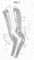
- Fig. 4 is a major part cross-sectional view illustrating an inner structure of a rear grasping portion
- Fig. 5 is a cross-sectional view along line V-V in Fig. 4
- Fig. 6 is a cross-sectional view along line VI-VI in Fig. 4
- Fig. 1 is a schematic configuration diagram of an endoscope system
- Fig. 2 is a side view of an endoscope, a universal cable of which is oriented in a first direction
- Fig. 3 is a side view of the endoscope, the universal cable of which is oriented in a second direction
- Fig. 4 is a major part cross-sectional view illustrating an inner structure of
- FIG. 7 is a diagram illustrating a favorable example of grasping when a rear grasping portion is grasped
- Fig. 8 is a diagram illustrating a favorable example of grasping when a front grasping portion is grasped
- Fig. 9 is a diagram illustrating a state in which an endoscope is stored in a cleaning basin of a cleaning apparatus.
- An endoscope system 1 which is illustrated in Fig. 1 , includes an endoscope 2, a light source apparatus 3 configured to supply illuminating light to the endoscope 2, a video processor 4 including a camera control unit (CCU) configured to perform image processing on a video signal obtained as a result of image pickup by the endoscope 2, and a monitor 5 configured to display the video signal outputted from the video processor 4.
- a camera control unit CCU
- monitor 5 configured to display the video signal outputted from the video processor 4.
- the endoscope 2 is, for example, a urological endoscope.
- This endoscope 2 includes a long insertion portion 10 that can be inserted into a target region inside a subject, an operation portion 11 provided so as to be continuous with the proximal end side of the insertion portion 10, and a universal cable 12, which is a cable portion extending out from the operation portion 11.
- a major part of the insertion portion 10 includes a rigid distal end portion 15, a bending portion 16 and a flexible tube portion 17 having flexibility, which are provided in this order from the distal end side.
- an image pickup unit incorporating an image pickup device such as a CCD or a CMOS is held, and a signal wire inserted in the insertion portion 10 is electrically connected to the image pickup unit.
- an illuminating optical system is held, and a light guide bundle inserted in the insertion portion 10 is optically connected to the illuminating optical system.
- a treatment instrument channel port is provided, and a treatment instrument channel inserted in the insertion portion 10 communicates with the treatment instrument channel port (none of these components illustrated).
- the bending portion 16 is bendable, for example, only in two directions, up and down, according to a bending operation performed via the operation portion 11. Note that the bending portion 16 may be configured to be bendable in four directions, up/down and left/right.
- the flexible tube portion 17 includes a flexible tubular member that can be bent passively.
- the operation portion 11 includes an operation portion body 20 provided so as to be continuous with the proximal end side of the insertion portion 10, a distal end rotating portion 21 interposed between the insertion portion 10 and the operation portion body 20, and a rear grasping portion 22 provided so as to be continuous with the proximal end side of the operation portion body 20.
- the operation portion body 20 includes, for example, a substantially elliptic cylindrical member, and extends along a first longitudinal axis O1 set coaxially with an insertion axis O of the insertion portion 10.
- a front grasping portion 25 which is a first grasping portion for, e.g., a surgeon to grasp the operation portion 11 along the insertion axis O direction, is set.
- a bending operation lever 26 for performing an operation to bend the bending portion 16 is provided.
- the bending operation lever 26 has, for example, a cantilevered L shape resulting from a lever portion 26a and a finger rest portion 26b, which is provided on the free end side of the lever portion 26a, being integrally formed, and the fixed end side of the lever portion 26a is pivotally supported by a side portion of the operation portion body 20.
- the bending operation lever 26 is joined to a well-known wire pulling mechanism (not illustrated) provided in the operation portion body 20. Consequently, upon the bending operation lever 26 being operated so as to pivot, wires inserted in the insertion portion 10 are pulled or loosened, which causes the bending portion 16 to bend.
- a projecting-shape finger hook portion 27 is provided at a region on the opposite side of the finger rest portion 26b across the operation portion body 20.
- the distal end side of the distal end rotating portion 21 is continuous with the proximal end side of the insertion portion 10 via the bend preventing portion 30.
- a treatment instrument insertion port 31 is provided so as to project, and the treatment instrument insertion port 31 communicates with the treatment instrument channel inside the distal end rotating portion 21.
- the proximal end side of the distal end rotating portion 21 is pivotally joined to the distal end side of the operation portion body 20 via a rotation mechanism 32.
- the rotation mechanism 32 in the present embodiment is capable of, for example, pivoting the distal end rotating portion 21 around the first longitudinal axis O1 of the operation portion body 20 within a pivot range of 180°. Pivoting of the distal end rotating portion 21 causes the treatment instrument insertion port 31 to be pivoted integrally with the insertion portion 10 and thus enables the treatment instrument insertion port 31 to be moved to an optimum position according to a state of grasping of the operation portion 11 (see Figs. 2 and 3 ).
- the pivot range of the rotation mechanism 32 is not limited to 180°, and can be set, for example, as an arbitrary angular range of no more than 360°.
- the rear grasping portion 22 includes, for example, a substantially elliptic cylindrical shape, and extends along a second longitudinal axis O2, which is a direction flexed relative to the first longitudinal axis O1.
- the rear grasping portion 22 is disposed in a flexed manner on the proximal end side of the operation portion body 20 so that an angle ⁇ on the minor angle side of the second longitudinal axis 02 relative to the first longitudinal axis O1 is, for example, an obtuse angle of 105°. Consequently, the rear grasping portion 22 functions as a second grasping portion that enables the operation portion 11 to be grasped in a direction that is different from the direction of grasping of the front grasping portion 25.
- the bending operation lever 26 projects on the outer side in the direction of flexion between the operation portion body 20 and the rear grasping portion 22 so that when the bending operation lever 26 is in a neutral state in which no bending operation is performed, the finger rest portion 26b is positioned at a rough center of an angle ⁇ formed between the first longitudinal axis O1 and the second longitudinal axis O2 on the major angle side.
- the finger hook portion 27 is disposed on the inner side in the direction of flexion between the operation portion body 20 and the rear grasping portion 22 so as to project at a rough center of the angle ⁇ between the first longitudinal axis O1 and the second longitudinal axis O2 on the minor angle side.
- a recess portion 28 is provided in a back face of the rear grasping portion 22, and in the recess portion 28, switches 29 for various kinds of endoscope functions are provided.
- the universal cable 12 is a composite cable that allows insertion of, e.g., various signal wires and a light guide extending from the distal end side of the insertion portion 10 to the operation portion 11 through the inside of the insertion portion 10 and further extending out from the operation portion 11. Also, the universal cable 12 may allow insertion of, e.g., an air/water feeding tube extending out from an air/water feeding apparatus (not illustrated).
- the universal cable 12 extends out from the proximal end side of the rear grasping portion 22. Also, at an extension end of the universal cable 12, an endoscope connector 35 that is connectable to the light source apparatus 3 is provided. Furthermore, a signal cable 36a extends out from a side face portion of the endoscope connector 35, and at an extension end of the signal cable 36a, an electric connector portion 36b that is connectable to the video processor 4 is provided.
- a bend preventing portion 40 is provided as a tube portion covering the universal cable 12.
- the bend preventing portion 40 is intended to gradually change a stiffness of an area covering the universal cable 12 to prevent, e.g., buckling on the rear grasping portion 22 side of the universal cable 12.
- the bend preventing portion 40 is set so as to have a stiffness that is high on the rear grasping portion 22 side (that is, rigid) and is lower (that is, is more flexible) toward the extension end side from which the universal cable 12 is exposed.
- the bend preventing portion 40 is joined to the proximal end side of the rear grasping portion 22 via a movable joint portion 41. Then, the interposition of the movable joint portion 41 enables a direction of the bend preventing portion 40 to be changed to a first direction oriented to the inner side in the flexion direction of the rear grasping portion 22 relative to the operation portion body 20 (see Fig. 2 ) and a second direction oriented to the outer side in the flexion direction of the rear grasping portion 22 relative to the operation portion body 20 (see Fig. 3 ).
- the first direction be, for example, inclined to the inner side in the flexion direction relative to the direction of the second longitudinal axis O2 of the rear grasping portion 22 within a range of 20 to 40 degrees, and in the present embodiment, an angle ⁇ 1 of the inclination of the first direction relative to the second longitudinal axis 02 is set at approximately 35 degrees.
- the second direction be, for example, inclined to the outer side in the flexion direction relative to the direction of the second longitudinal axis O2 of the rear grasping portion 22 at an angle of no less than 80 degrees, and in the present embodiment, an angle ⁇ 2 of the inclination of the second direction relative to the second longitudinal axis 02 is set at approximately 90 degrees. Consequently, the second direction in the present embodiment is set in, for example, a direction that is substantially parallel to the first longitudinal axis O1 within an error range of around ⁇ 15 degrees.
- a guide barrel 45 for allowing insertion of cables and the like such as various signals wires, the light guide and the air/water feeding tube that extend out from the operation portion body 20 side is provided fixedly.
- an opening portion 22a is provided, and a bracket 46 fixedly provided on the proximal end side of the guide barrel 45 is faced to the opening portion 22a.
- a substantially cylindrical shaft member 47 is arranged in the opening portion 22a.
- An outward flange 47a is provided at an outer circumferential portion of the shaft member 47, and the outward flange 47a is fastened to the bracket 46 with screws 48 (see Fig. 5 ), and the shaft member 47 is thus held in the rear grasping portion 22.
- an outer barrel member 50 fitted on the outer circumferential side of the shaft member 47 is provided inside the movable joint portion 41.
- an inner barrel member 51 is fitted in the inner circumferential side of the shaft member 47.
- an engagement portion 51a that is engageable with an end face of the shaft member is provided, and the inner barrel member 51 is fastened to the outer barrel member 50 with screws 52 (see Fig. 6 ). Consequently, the movable joint portion 41 is joined to the rear grasping portion 22 so as to be pivotable with a center axis of the shaft member 47 as a pivot axis O3.
- the pivot axis O3 is set so as to be inclined to the outer side in the flexion direction relative to the second longitudinal axis O2.
- a stopper pin 49 is provided at the outward flange 47a of the shaft member 47.
- a projection portion 50a oriented toward the outward flange 47a of the shaft member 47 is provided in the outer barrel member 50. Then, a range from a rotational position at which one side of the projection portion 50a abuts against the stopper pin 49 to a rotational position at which the other side of the projection portion 50a abuts against the stopper pin 49 is defined as the range of pivoting of the movable joint portion 41.
- an O-shaped ring 55 is arbitrarily fitted to each of, e.g., a portion of sliding between the rear grasping portion 22 and the movable joint portion 41, and a part of bonding between the movable joint portion 41 and the bend preventing portion 40 to ensure water tightness of these portions.
- the bend preventing portion 40 is oriented in the second direction through a pivoting operation of the movable joint portion 41.
- the treatment instrument insertion port 31 is disposed on the outer side in the flexion direction (opposite side of the rear grasping portion 22 with reference to the first longitudinal axis O1) through pivoting of the distal end rotating portion 21.
- the universal cable 12 extends downward with the outer side in the flexion direction of the rear grasping portion 22 relative to the operation portion body 20 as a starting point, and a gravity center C of the operation portion 11 is positioned in the vicinity of the second longitudinal axis 02 of the rear grasping portion 22.
- the insertion portion 10 (flexible tube portion 17) can be prevented from bowing unnecessarily, enabling a bending motion of the bending portion 16 with favorable responsiveness to an operation via the bending operation lever 26.
- decrease in responsiveness of bending motion of the bending portion 16 to an operation of the bending operation lever 26 due to generation of, e.g., unintended tension or bowing in the wires inserted in the insertion portion 10 resulting from unnecessary bowing of the insertion portion 10 can be suppressed.
- the insertion portion 10 can be prevented from bowing unnecessarily, followability of torque for the distal end side when an operation to twist the insertion portion 10 can be enhanced and enhancement in durability of the insertion portion 10 can be expected.
- the universal cable 12 can be made to extend with a part that is just in the vicinity of the forearm as a starting point.
- the universal cable 12 can be prevented from coming into contact with, e.g., an abdominal region of the surgeon, enabling prevention of a failure due to, e.g., disconnection in the universal cable 12.
- a bow of the insertion portion 10 increases, for example, the possibility of occurrence of decrease in followability of torque for the distal end side when an operation to twist the insertion portion 10 is performed and/or decrease in durability of the insertion portion 10. Also, since the bend preventing portion 40 is positioned away from the forearm of the hand grasping the rear grasping portion 22, the universal cable 12 extends with a position away from the forearm as a starting point, which makes it difficult to handle the universal cable 12.
- the bend preventing portion 40 is oriented in the second direction through a pivoting operation of the movable joint portion 41.
- the treatment instrument insertion port 31 is disposed on the inner side in the flexion direction (side that is the same as the side on which the rear grasping portion 22 is disposed with respect to the first longitudinal axis O1) through pivoting of the distal end rotating portion 21.
- the universal cable 12 extends downward from the outer side in the flexion direction of the rear grasping portion 22 via the vicinity of the wrist of the hand grasping the front grasping portion 25, and the gravity center C of the operation portion 11 is positioned in the vicinity of the first longitudinal axis O1 of the front grasping portion 25.
- the operation portion body 20 can easily be maintained vertically. Therefore, in the section from the operation portion 11 to a subject, the insertion portion 10 (flexible tube portion 17) can be prevented from bowing unnecessarily, enabling a bending motion of the bending portion 16 with favorable responsiveness to an operation of the bending operation lever 26.
- the universal cable 12 extending through the vicinity of the hand grasping the operation portion 11, for example, even when the direction of the operation portion 11 is changed during, e.g., surgery, handling of the universal cable 12 is easy, enabling more favorable operability.
- the universal cable 12 is less likely to move around.
- the universal cable 12 can be prevented from mistakenly coming into contact with the insertion portion 10.
- a bow of the insertion portion 10 increases, for example, the possibility of occurrence of decrease in followability of torque for the distal end side when an operation to twist the insertion portion 10 is performed and/or decrease in durability of the insertion portion 10. Also, since the universal cable 12 extends via the front side of the operation portion 11, handling of the universal cable 12 is difficult, and furthermore, workability for the treatment instrument insertion port 31 is decreased.
- the bend preventing portion 40 is oriented in the first direction through a pivoting operation of the movable joint portion 41.
- the treatment instrument insertion port 31 is disposed on the inner side in the flexion direction through pivoting of the distal end rotating portion 21.
- the bend preventing portion 40 covering the universal cable 12 extending out from the proximal end side of the rear grasping portion 22 is joined to the proximal end side of the rear grasping portion 22 via the movable joint portion 41 so that the direction of the bend preventing portion 40 can be changed by the movable joint portion 41 to the first direction oriented to the inner side in the flexion direction of the rear grasping portion 22 relative to the operation portion body 20 and the second direction oriented to the outer side in the flexion direction of the rear grasping portion 22 relative to the operation portion body 20, enabling both compact storage and favorable graspability and operability.
- the direction of the bend preventing portion 40 can be change to another direction.
- the direction of the bend preventing portion 40 can be changed to a third direction oriented to the outer side in the flexion direction of the rear grasping portion 22 and inclined to a lateral side in the flexion direction.
- Such change of the direction of the bend preventing portion 40 to the third direction further can effectively suppress interference between the hand and/or the arm of the hand grasping the rear grasping portion 22 and the bend preventing portion 40 and the universal cable 12 in addition to the respective effects described above.
- the bend preventing portion 40 can be directed toward the light source apparatus 3 and/or the video processor 4. Accordingly, the universal cable 12 can be made to extend with a shortest distance to the light source apparatus 3 and/or the video processor 4. Therefore, it is possible to, when the operation portion 11 is advanced/retracted or twisted during surgery, prevent shortage in length of the universal cable 12 and difficulty in operation due to the shortage.
- a movable joint portion 65 including a flexible tube such as what is called a gooseneck tube can be employed.
- the movable joint portion 65 is exposed to the outside; however, for ensuring water tightness of the inside of an operation portion 11, the outer side of the movable joint portion 65 is covered by, e.g., a rubber tube.
- a movable joint portion 66 via which a bend preventing portion 40 is pivoted around a pivot axis 04 orthogonal to a second longitudinal axis 02 can be employed.
Landscapes
- Health & Medical Sciences (AREA)
- Life Sciences & Earth Sciences (AREA)
- Surgery (AREA)
- Physics & Mathematics (AREA)
- Engineering & Computer Science (AREA)
- Optics & Photonics (AREA)
- Biomedical Technology (AREA)
- General Health & Medical Sciences (AREA)
- Pathology (AREA)
- Nuclear Medicine, Radiotherapy & Molecular Imaging (AREA)
- Biophysics (AREA)
- Heart & Thoracic Surgery (AREA)
- Medical Informatics (AREA)
- Molecular Biology (AREA)
- Animal Behavior & Ethology (AREA)
- Radiology & Medical Imaging (AREA)
- Public Health (AREA)
- Veterinary Medicine (AREA)
- Astronomy & Astrophysics (AREA)
- General Physics & Mathematics (AREA)
- Mechanical Engineering (AREA)
- Endoscopes (AREA)
- Instruments For Viewing The Inside Of Hollow Bodies (AREA)
Abstract
Description
- The present invention relates to an endoscope including an operation portion allowing a plurality of grasping modes.
- Conventionally, endoscopes are used to perform observation of a target region inside a subject such as a body cavity and, as necessary, various kinds of treatment using a treatment instrument inserted in a treatment instrument channel, by inserting an elongated insertion portion into the subject.
- As this type of endoscope, a flexible endoscope in which a distal end portion, a bending portion and a flexible tube portion are arranged in this order from a distal end side has been widely used. When the insertion portion of such a flexible endoscope is inserted into a subject, a surgeon or the like grasps the flexible tube portion with one of his/her hands and pushes the insertion portion into the subject while grasping the operation portion with the other of his/her hands. In this case, the surgeon or the like can bend the bending portion in a desired direction by operating an operation knob arranged at the operation portion with the hand grasping the operation portion.
- For example, when endoscopic observation or treatment of, e.g., a urinary organ or a nasal cavity is performed, the insertion portion is inserted substantially horizontally to a subject such as a recumbent patient. In order to enhance such insertability to a target region, for example, Japanese Patent Application Laid-Open Publication No.
2009-189684 2009-189684 - However, as in the technique disclosed in Japanese Patent Application Laid-Open Publication No.
2009-189684 - Also, where the operation portion is formed so as to be flexed in an L shape, a distance of a position of a gravity center of the operation portion from the grasping portion tends to increase, and such increase in distance of the position of the gravity center from the grasping portion may cause difficulties in ensuring favorable graspability and operability, such as a strain being put on a wrist of, e.g., a surgeon grasping the grasping portion.
- The present invention has been made in view of the aforementioned circumstances, and an object of the present invention is to provide an endoscope that enables achievement of both compact storage and favorable graspability and operability.
- An endoscope according to an aspect of the present invention includes: an operation portion body provided so as to be continuous with a proximal end side of an insertion portion; a rear grasping portion provided so as to be continuous with a proximal end side of the operation portion body, the rear grasping portion extending along a second longitudinal axis that is a direction flexed relative to a first longitudinal axis along which the operation portion body extends; a cable portion extending out from a proximal end side of the rear grasping portion; a tube portion covering the cable portion on the proximal end side of the rear grasping portion; and a movable joint portion configured to join the tube portion to the proximal end side of the rear grasping portion so that a direction of the tube portion can be changed to a plurality of directions including a first direction oriented to an inner side in a flexion direction of the rear grasping portion relative to the operation portion body and a second direction oriented to an outer side in the flexion direction of the rear grasping portion relative to the operation portion body.
-
-
Fig. 1 is a schematic configuration diagram of an endoscope system; -
Fig. 2 is a side view of an endoscope, a universal cable of which is oriented in a first direction; -
Fig. 3 is a side view of the endoscope, the universal cable of which is oriented in a second direction; -
Fig. 4 is a major part cross-sectional view illustrating an inner structure of a rear grasping portion; -
Fig. 5 is a cross-sectional view along line V-V inFig. 4 ; -
Fig. 6 is a cross-sectional view along line VI-VI inFig. 4 ; -
Fig. 7 is a diagram illustrating a favorable example of grasping when a rear grasping portion is grasped; -
Fig. 8 is a diagram illustrating a favorable example of grasping when a front grasping portion is grasped; -
Fig. 9 is a diagram illustrating a state in which an endoscope is stored in a cleaning basin of a cleaning apparatus; -
Fig. 10 relates to a first modification and is a back view of an endoscope; -
Fig. 11 relates to a second modification and is a side view of an endoscope; -
Fig. 12 relates to a third modification and is a back view of an endoscope; and -
Fig. 13 relates to the third modification and is a side view of the endoscope. - A mode of the present invention will be described below with reference to the drawings. The drawings relate to an embodiment of the present invention:
Fig. 1 is a schematic configuration diagram of an endoscope system;Fig. 2 is a side view of an endoscope, a universal cable of which is oriented in a first direction;Fig. 3 is a side view of the endoscope, the universal cable of which is oriented in a second direction;Fig. 4 is a major part cross-sectional view illustrating an inner structure of a rear grasping portion;Fig. 5 is a cross-sectional view along line V-V inFig. 4 ;,Fig. 6 is a cross-sectional view along line VI-VI inFig. 4 ;Fig. 7 is a diagram illustrating a favorable example of grasping when a rear grasping portion is grasped;Fig. 8 is a diagram illustrating a favorable example of grasping when a front grasping portion is grasped; andFig. 9 is a diagram illustrating a state in which an endoscope is stored in a cleaning basin of a cleaning apparatus. - An endoscope system 1, which is illustrated in
Fig. 1 , includes anendoscope 2, alight source apparatus 3 configured to supply illuminating light to theendoscope 2, avideo processor 4 including a camera control unit (CCU) configured to perform image processing on a video signal obtained as a result of image pickup by theendoscope 2, and amonitor 5 configured to display the video signal outputted from thevideo processor 4. - The
endoscope 2 according to the present embodiment illustrated inFigs. 1 to 3 is, for example, a urological endoscope. Thisendoscope 2 includes along insertion portion 10 that can be inserted into a target region inside a subject, anoperation portion 11 provided so as to be continuous with the proximal end side of theinsertion portion 10, and auniversal cable 12, which is a cable portion extending out from theoperation portion 11. - A major part of the
insertion portion 10 includes a rigiddistal end portion 15, abending portion 16 and aflexible tube portion 17 having flexibility, which are provided in this order from the distal end side. - In the
distal end portion 15, an image pickup unit incorporating an image pickup device such as a CCD or a CMOS is held, and a signal wire inserted in theinsertion portion 10 is electrically connected to the image pickup unit. Also, in thedistal end portion 15, an illuminating optical system is held, and a light guide bundle inserted in theinsertion portion 10 is optically connected to the illuminating optical system. Also, in thedistal end portion 15, a treatment instrument channel port is provided, and a treatment instrument channel inserted in theinsertion portion 10 communicates with the treatment instrument channel port (none of these components illustrated). - The
bending portion 16 is bendable, for example, only in two directions, up and down, according to a bending operation performed via theoperation portion 11. Note that thebending portion 16 may be configured to be bendable in four directions, up/down and left/right. - The
flexible tube portion 17 includes a flexible tubular member that can be bent passively. - As illustrated in
Figs. 2 and3 , theoperation portion 11 includes anoperation portion body 20 provided so as to be continuous with the proximal end side of theinsertion portion 10, a distalend rotating portion 21 interposed between theinsertion portion 10 and theoperation portion body 20, and arear grasping portion 22 provided so as to be continuous with the proximal end side of theoperation portion body 20. - The
operation portion body 20 includes, for example, a substantially elliptic cylindrical member, and extends along a first longitudinal axis O1 set coaxially with an insertion axis O of theinsertion portion 10. - In a distal end-side area of the
operation portion body 20, afront grasping portion 25, which is a first grasping portion for, e.g., a surgeon to grasp theoperation portion 11 along the insertion axis O direction, is set. - Also, on the proximal end side of the
operation portion body 20, a bending operation lever 26 for performing an operation to bend thebending portion 16 is provided. Thebending operation lever 26 has, for example, a cantilevered L shape resulting from alever portion 26a and afinger rest portion 26b, which is provided on the free end side of thelever portion 26a, being integrally formed, and the fixed end side of thelever portion 26a is pivotally supported by a side portion of theoperation portion body 20. Thebending operation lever 26 is joined to a well-known wire pulling mechanism (not illustrated) provided in theoperation portion body 20. Consequently, upon thebending operation lever 26 being operated so as to pivot, wires inserted in theinsertion portion 10 are pulled or loosened, which causes thebending portion 16 to bend. - Furthermore, on the proximal end side of the
operation portion body 20, a projecting-shapefinger hook portion 27 is provided at a region on the opposite side of thefinger rest portion 26b across theoperation portion body 20. - The distal end side of the distal
end rotating portion 21 is continuous with the proximal end side of theinsertion portion 10 via thebend preventing portion 30. - Also, at a side portion of the distal
end rotating portion 21, a treatmentinstrument insertion port 31 is provided so as to project, and the treatmentinstrument insertion port 31 communicates with the treatment instrument channel inside the distalend rotating portion 21. - Furthermore, the proximal end side of the distal
end rotating portion 21 is pivotally joined to the distal end side of theoperation portion body 20 via arotation mechanism 32. Here, therotation mechanism 32 in the present embodiment is capable of, for example, pivoting the distalend rotating portion 21 around the first longitudinal axis O1 of theoperation portion body 20 within a pivot range of 180°. Pivoting of the distalend rotating portion 21 causes the treatmentinstrument insertion port 31 to be pivoted integrally with theinsertion portion 10 and thus enables the treatmentinstrument insertion port 31 to be moved to an optimum position according to a state of grasping of the operation portion 11 (seeFigs. 2 and3 ). Here, the pivot range of therotation mechanism 32 is not limited to 180°, and can be set, for example, as an arbitrary angular range of no more than 360°. - The
rear grasping portion 22 includes, for example, a substantially elliptic cylindrical shape, and extends along a second longitudinal axis O2, which is a direction flexed relative to the first longitudinal axis O1. - In the present embodiment, the
rear grasping portion 22 is disposed in a flexed manner on the proximal end side of theoperation portion body 20 so that an angle α on the minor angle side of the secondlongitudinal axis 02 relative to the first longitudinal axis O1 is, for example, an obtuse angle of 105°. Consequently, therear grasping portion 22 functions as a second grasping portion that enables theoperation portion 11 to be grasped in a direction that is different from the direction of grasping of thefront grasping portion 25. - In this case, in order to achieve a same level of operability in bending operation regardless of whether the
front grasping portion 25 or therear grasping portion 22 is grasped, the bending operation lever 26 projects on the outer side in the direction of flexion between theoperation portion body 20 and therear grasping portion 22 so that when thebending operation lever 26 is in a neutral state in which no bending operation is performed, thefinger rest portion 26b is positioned at a rough center of an angle β formed between the first longitudinal axis O1 and the second longitudinal axis O2 on the major angle side. On the other hand, thefinger hook portion 27 is disposed on the inner side in the direction of flexion between theoperation portion body 20 and therear grasping portion 22 so as to project at a rough center of the angle α between the first longitudinal axis O1 and the second longitudinal axis O2 on the minor angle side. - Also, in the vicinity of the
bending operation lever 26, arecess portion 28 is provided in a back face of therear grasping portion 22, and in therecess portion 28,switches 29 for various kinds of endoscope functions are provided. - The
universal cable 12 is a composite cable that allows insertion of, e.g., various signal wires and a light guide extending from the distal end side of theinsertion portion 10 to theoperation portion 11 through the inside of theinsertion portion 10 and further extending out from theoperation portion 11. Also, theuniversal cable 12 may allow insertion of, e.g., an air/water feeding tube extending out from an air/water feeding apparatus (not illustrated). - The
universal cable 12 extends out from the proximal end side of therear grasping portion 22. Also, at an extension end of theuniversal cable 12, anendoscope connector 35 that is connectable to thelight source apparatus 3 is provided. Furthermore, asignal cable 36a extends out from a side face portion of theendoscope connector 35, and at an extension end of thesignal cable 36a, anelectric connector portion 36b that is connectable to thevideo processor 4 is provided. - Here, on the proximal end side of the
rear grasping portion 22, abend preventing portion 40 is provided as a tube portion covering theuniversal cable 12. In the present embodiment, thebend preventing portion 40 is intended to gradually change a stiffness of an area covering theuniversal cable 12 to prevent, e.g., buckling on therear grasping portion 22 side of theuniversal cable 12. Thus, thebend preventing portion 40 is set so as to have a stiffness that is high on therear grasping portion 22 side (that is, rigid) and is lower (that is, is more flexible) toward the extension end side from which theuniversal cable 12 is exposed. - The
bend preventing portion 40 is joined to the proximal end side of therear grasping portion 22 via a movablejoint portion 41. Then, the interposition of the movablejoint portion 41 enables a direction of thebend preventing portion 40 to be changed to a first direction oriented to the inner side in the flexion direction of therear grasping portion 22 relative to the operation portion body 20 (seeFig. 2 ) and a second direction oriented to the outer side in the flexion direction of therear grasping portion 22 relative to the operation portion body 20 (seeFig. 3 ). - In this case, it is desirable that the first direction be, for example, inclined to the inner side in the flexion direction relative to the direction of the second longitudinal axis O2 of the
rear grasping portion 22 within a range of 20 to 40 degrees, and in the present embodiment, an angle θ1 of the inclination of the first direction relative to the secondlongitudinal axis 02 is set at approximately 35 degrees. - Also, it is desirable that the second direction be, for example, inclined to the outer side in the flexion direction relative to the direction of the second longitudinal axis O2 of the
rear grasping portion 22 at an angle of no less than 80 degrees, and in the present embodiment, an angle θ2 of the inclination of the second direction relative to the secondlongitudinal axis 02 is set at approximately 90 degrees. Consequently, the second direction in the present embodiment is set in, for example, a direction that is substantially parallel to the first longitudinal axis O1 within an error range of around ±15 degrees. - Next, a structure of joining of the movable
joint portion 41 to therear grasping portion 22 will be described in detail. - As illustrated in
Fig. 4 , inside therear grasping portion 22, aguide barrel 45 for allowing insertion of cables and the like such as various signals wires, the light guide and the air/water feeding tube that extend out from theoperation portion body 20 side is provided fixedly. - Also, on the proximal end side of the
rear grasping portion 22, anopening portion 22a is provided, and abracket 46 fixedly provided on the proximal end side of theguide barrel 45 is faced to theopening portion 22a. - Also, in the
opening portion 22a, a substantiallycylindrical shaft member 47 is arranged. Anoutward flange 47a is provided at an outer circumferential portion of theshaft member 47, and theoutward flange 47a is fastened to thebracket 46 with screws 48 (seeFig. 5 ), and theshaft member 47 is thus held in therear grasping portion 22. - On the other hand, inside the movable
joint portion 41, anouter barrel member 50 fitted on the outer circumferential side of theshaft member 47 is provided. Also, aninner barrel member 51 is fitted in the inner circumferential side of theshaft member 47. At an end portion of theinner barrel member 51, anengagement portion 51a that is engageable with an end face of the shaft member is provided, and theinner barrel member 51 is fastened to theouter barrel member 50 with screws 52 (seeFig. 6 ). Consequently, the movablejoint portion 41 is joined to therear grasping portion 22 so as to be pivotable with a center axis of theshaft member 47 as a pivot axis O3. - In this case, in order to make the inclination angle θ2 of the second direction larger than the inclination angle θ1 of the first direction, the pivot axis O3 is set so as to be inclined to the outer side in the flexion direction relative to the second longitudinal axis O2.
- Also, in order to define a range of pivoting of the movable
joint portion 41, astopper pin 49 is provided at theoutward flange 47a of theshaft member 47. On the other hand, in theouter barrel member 50, aprojection portion 50a oriented toward theoutward flange 47a of theshaft member 47 is provided. Then, a range from a rotational position at which one side of theprojection portion 50a abuts against thestopper pin 49 to a rotational position at which the other side of theprojection portion 50a abuts against thestopper pin 49 is defined as the range of pivoting of the movablejoint portion 41. - Note that an O-shaped
ring 55 is arbitrarily fitted to each of, e.g., a portion of sliding between the rear graspingportion 22 and the movablejoint portion 41, and a part of bonding between the movablejoint portion 41 and thebend preventing portion 40 to ensure water tightness of these portions. - Next, a favorable example of grasping for grasping the
endoscope 2 configured as described above will be described with reference toFigs. 7 and8 . - For example, as illustrated in
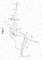
Fig. 7 , when, e.g., a surgeon grasps therear grasping portion 22 in such a manner that the operation portion body 20 (first longitudinal axis O1) is substantially horizontal, thebend preventing portion 40 is oriented in the second direction through a pivoting operation of the movablejoint portion 41. Here, in such grasping method, in order to operate, e.g., a treatment instrument from above the hand grasping therear grasping portion 22, the treatmentinstrument insertion port 31 is disposed on the outer side in the flexion direction (opposite side of therear grasping portion 22 with reference to the first longitudinal axis O1) through pivoting of the distalend rotating portion 21. - Then, as a result of the
bend preventing portion 40 being directed in the second direction, theuniversal cable 12 extends downward with the outer side in the flexion direction of therear grasping portion 22 relative to theoperation portion body 20 as a starting point, and a gravity center C of theoperation portion 11 is positioned in the vicinity of the secondlongitudinal axis 02 of therear grasping portion 22. - Therefore, unnecessary moment acting on the hand grasping the
operation portion 11 can be suppressed, and a strain put on, e.g., the wrist can be reduced, enabling achievement of favorable graspability. - In addition, since unnecessary moment acting on the hand grasping the
operation portion 11 can be suppressed, it is easy to maintain theoperation portion body 20 horizontally. Therefore, in a section from theoperation portion 11 to a subject, the insertion portion 10 (flexible tube portion 17) can be prevented from bowing unnecessarily, enabling a bending motion of the bendingportion 16 with favorable responsiveness to an operation via the bendingoperation lever 26. In other words, decrease in responsiveness of bending motion of the bendingportion 16 to an operation of the bendingoperation lever 26 due to generation of, e.g., unintended tension or bowing in the wires inserted in theinsertion portion 10 resulting from unnecessary bowing of theinsertion portion 10 can be suppressed. - Also, since the
insertion portion 10 can be prevented from bowing unnecessarily, followability of torque for the distal end side when an operation to twist theinsertion portion 10 can be enhanced and enhancement in durability of theinsertion portion 10 can be expected. - Also, since the
bend preventing portion 40 extends along the forearm of the hand grasping therear grasping portion 22, theuniversal cable 12 can be made to extend with a part that is just in the vicinity of the forearm as a starting point. - Therefore, e.g., when a direction of the
operation portion 11 is changed during surgery, handling of theuniversal cable 12 is easy, enabling provision of more favorable operability. In other words, for example, even if a position of theoperation portion 11 is rotated with the first longitudinal axis O1 as a center during, e.g., surgery, theuniversal cable 12 is less likely to move around. Therefore, theuniversal cable 12 can be prevented from coming into contact with, e.g., an abdominal region of the surgeon, enabling prevention of a failure due to, e.g., disconnection in theuniversal cable 12. - On the other hand, for example, as indicated by the alternate long and two short dashes lines in
Fig. 7 , if thebend preventing portion 40 is oriented in the secondlongitudinal axis 02 direction with no movable joint portion interposed, a gravity center C' of theoperation portion 11 is positioned away from the secondlongitudinal axis 02. Therefore, unnecessary moment acts on the hand grasping theoperation portion 11, and a strain is thus put on, e.g., the wrist. In addition, the generated moment makes it difficult to maintain theoperation portion body 20 horizontally, and in the section from theoperation portion 11 to the subject, an unnecessary bow is thus more likely to occur in theinsertion portion 10, and a bending motion of the bendingportion 16 is thus sluggish to an operation of the bendingoperation lever 26. Furthermore, a bow of theinsertion portion 10 increases, for example, the possibility of occurrence of decrease in followability of torque for the distal end side when an operation to twist theinsertion portion 10 is performed and/or decrease in durability of theinsertion portion 10. Also, since thebend preventing portion 40 is positioned away from the forearm of the hand grasping therear grasping portion 22, theuniversal cable 12 extends with a position away from the forearm as a starting point, which makes it difficult to handle theuniversal cable 12. - Next, for example, as illustrated in
Fig. 8 , where, e.g., a surgeon grasps thefront grasping portion 25 in such a manner that the operation portion body 20 (first longitudinal axis O1) is substantially vertical, thebend preventing portion 40 is oriented in the second direction through a pivoting operation of the movablejoint portion 41. In such grasping method, in order to operate, e.g., a treatment instrument from above the hand grasping thefront grasping portion 25, the treatmentinstrument insertion port 31 is disposed on the inner side in the flexion direction (side that is the same as the side on which therear grasping portion 22 is disposed with respect to the first longitudinal axis O1) through pivoting of the distalend rotating portion 21. - Consequently, the
universal cable 12 extends downward from the outer side in the flexion direction of therear grasping portion 22 via the vicinity of the wrist of the hand grasping thefront grasping portion 25, and the gravity center C of theoperation portion 11 is positioned in the vicinity of the first longitudinal axis O1 of the front graspingportion 25. - Therefore, unnecessary moment can be prevented from acting on the hand grasping the
operation portion 11, enabling reduction of a strain put on, e.g., the wrist and achievement of favorable graspability. - In addition, since unnecessary moment acting on the hand grasping the
operation portion 11 can be suppressed, theoperation portion body 20 can easily be maintained vertically. Therefore, in the section from theoperation portion 11 to a subject, the insertion portion 10 (flexible tube portion 17) can be prevented from bowing unnecessarily, enabling a bending motion of the bendingportion 16 with favorable responsiveness to an operation of the bendingoperation lever 26. - Also, as a result of the
universal cable 12 extending through the vicinity of the hand grasping theoperation portion 11, for example, even when the direction of theoperation portion 11 is changed during, e.g., surgery, handling of theuniversal cable 12 is easy, enabling more favorable operability. In other word, for example, where the position of theoperation portion 11 is rotated with the first longitudinal axis O1 as a center during, e.g., surgery, theuniversal cable 12 is less likely to move around. Also, since theuniversal cable 12 extends through the vicinity of the hand grasping theoperation portion 11, theuniversal cable 12 can be prevented from mistakenly coming into contact with theinsertion portion 10. - On the other hand, for example, as indicated by the alternate long and two short dashes lines in
Fig. 8 , if thebend preventing portion 40 is oriented in the secondlongitudinal axis 02 direction with no movable joint portion interposed, a gravity center C' of theoperation portion 11 is positioned away from the first longitudinal axis O1. Therefore, unnecessary moment acts on the hand grasping theoperation portion 11, and a strain is thus put on, e.g., the wrist. In addition, the generated moment makes it difficult to maintain theoperation portion body 20 vertically, and in the section from theoperation portion 11 to the subject, an unnecessary bow is more likely to occur in theinsertion portion 10, and a bending motion of the bendingoperation lever 26 is thus sluggish to an operation of the bendingportion 16. Furthermore, a bow of theinsertion portion 10 increases, for example, the possibility of occurrence of decrease in followability of torque for the distal end side when an operation to twist theinsertion portion 10 is performed and/or decrease in durability of theinsertion portion 10. Also, since theuniversal cable 12 extends via the front side of theoperation portion 11, handling of theuniversal cable 12 is difficult, and furthermore, workability for the treatmentinstrument insertion port 31 is decreased. - Next, a favorable storage example when the
endoscope 2 configured as described above is stored will be described with reference toFig. 9 . - For example, as illustrated in
Fig. 9 , when theendoscope 2 is stored in acleaning basin 60 of a cleaning machine, thebend preventing portion 40 is oriented in the first direction through a pivoting operation of the movablejoint portion 41. Here, in this case, for example, the treatmentinstrument insertion port 31 is disposed on the inner side in the flexion direction through pivoting of the distalend rotating portion 21. - Consequently, interference between, e.g., a wall surface of the
cleaning basin 60 and thebend preventing portion 40 can be prevented, and theendoscope 2 can be stored in thecleaning basin 60 compactly compared to, e.g., a case where thebend preventing portion 40 is oriented in the second longitudinal axis O2 direction or the second direction (see the alternate long and two short dashes lines inFig. 9 ). - According to such embodiment, in the
endoscope 2 including therear grasping portion 22 extending along the second longitudinal axis O2 that is a direction flexed relative to the first longitudinal axis O1 along which theoperation portion body 20 extends, thebend preventing portion 40 covering theuniversal cable 12 extending out from the proximal end side of therear grasping portion 22 is joined to the proximal end side of therear grasping portion 22 via the movablejoint portion 41 so that the direction of thebend preventing portion 40 can be changed by the movablejoint portion 41 to the first direction oriented to the inner side in the flexion direction of therear grasping portion 22 relative to theoperation portion body 20 and the second direction oriented to the outer side in the flexion direction of therear grasping portion 22 relative to theoperation portion body 20, enabling both compact storage and favorable graspability and operability. - Here, although the above embodiment has been described in terms of an example in which the direction of the
bend preventing portion 40 is changed by the movablejoint portion 41 to the first direction oriented to the inner side in the flexion direction of therear grasping portion 22 and the second direction oriented to the outer side in the flexion direction of therear grasping portion 22, the direction of thebend preventing portion 40 can be change to another direction. For example, as illustrated inFig. 10 , the direction of thebend preventing portion 40 can be changed to a third direction oriented to the outer side in the flexion direction of therear grasping portion 22 and inclined to a lateral side in the flexion direction. Such change of the direction of thebend preventing portion 40 to the third direction further can effectively suppress interference between the hand and/or the arm of the hand grasping therear grasping portion 22 and thebend preventing portion 40 and theuniversal cable 12 in addition to the respective effects described above. Also, where thelight source apparatus 3 and/or thevideo processor 4 are disposed, for example, on a lateral side of a surgeon, thebend preventing portion 40 can be directed toward thelight source apparatus 3 and/or thevideo processor 4. Accordingly, theuniversal cable 12 can be made to extend with a shortest distance to thelight source apparatus 3 and/or thevideo processor 4. Therefore, it is possible to, when theoperation portion 11 is advanced/retracted or twisted during surgery, prevent shortage in length of theuniversal cable 12 and difficulty in operation due to the shortage. - Also, although the above embodiment has been described in terms of an example configuration of the movable
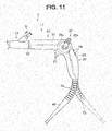
joint portion 41 via which thebend preventing portion 40 is pivoted around thepivot axis 03 extending out from the proximal end of therear grasping portion 22, instead of the movablejoint portion 41, for example, as illustrated inFig. 11 , a movablejoint portion 65 including a flexible tube such as what is called a gooseneck tube can be employed. Here, for simplicity of description, in the example illustrated inFig. 11 , the movablejoint portion 65 is exposed to the outside; however, for ensuring water tightness of the inside of anoperation portion 11, the outer side of the movablejoint portion 65 is covered by, e.g., a rubber tube. - Also, although the above embodiment has been described in terms of an example configuration of the movable
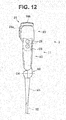
joint portion 41 via which thebend preventing portion 40 is pivoted around thepivot axis 03 extending out from the proximal end of therear grasping portion 22, instead of the movablejoint portion 41, for example, as illustrated inFigs. 12 and13 , a movablejoint portion 66 via which abend preventing portion 40 is pivoted around apivot axis 04 orthogonal to a secondlongitudinal axis 02 can be employed. - Note that the present invention is not limited to the embodiment and the respective modifications described above, various modifications and alternations are possible, and such modifications and alternations also fall within the technical scope of the present invention.
- The present application is filed claiming the priority from Japanese Patent Application No.
2015-246017
Claims (9)
- An endoscope comprising:an operation portion body provided so as to be continuous with a proximal end side of an insertion portion;a rear grasping portion provided so as to be continuous with a proximal end side of the operation portion body, the rear grasping portion extending along a second longitudinal axis that is a direction flexed relative to a first longitudinal axis along which the operation portion body extends;a cable portion extending out from a proximal end side of the rear grasping portion;a tube portion covering the cable portion on the proximal end side of the rear grasping portion; anda movable joint portion configured to join the tube portion to the proximal end side of the rear grasping portion so that a direction of the tube portion can be changed to a plurality of directions including a first direction oriented to an inner side in a flexion direction of the rear grasping portion relative to the operation portion body and a second direction oriented to an outer side in the flexion direction.
- The endoscope according to claim 1, wherein the movable joint portion can change the direction of the tube portion to a third direction oriented to the outer side in the flexion direction and inclined to a lateral side in the flexion direction.
- The endoscope according to claim 1, wherein the first direction is set in a direction inclined to the inner side in the flexion direction within a range of 20 to 40 degrees, relative to the second longitudinal axis.
- The endoscope according to claim 1, wherein the second direction is set in a direction inclined to the outer side in the flexion direction at an angle of no less than 80 degrees, relative to the second longitudinal axis.
- The endoscope according to claim 1, wherein the movable joint portion is pivotable around a pivot axis inclined to the outer side in the flexion direction relative to the second longitudinal axis.
- The endoscope according to claim 1, wherein the movable joint portion is pivotable around a pivot axis orthogonal to the second longitudinal axis.
- The endoscope according to claim 1, wherein the movable joint portion includes a flexible tube.
- The endoscope according to claim 1, comprising a front grasping portion provided on a distal end side relative to the rear grasping portion in the operation portion body, the front grasping portion being graspable along the first longitudinal axis.
- The endoscope according to claim 1, comprising:a distal end rotating portion interposed between the insertion portion and the operation portion body, the distal end rotating portion being pivotable around the first longitudinal axis relative to the operation portion body; anda treatment instrument insertion port provided in the distal end rotating portion.
Applications Claiming Priority (2)
| Application Number | Priority Date | Filing Date | Title |
|---|---|---|---|
| JP2015246017 | 2015-12-17 | ||
| PCT/JP2016/079064 WO2017104225A1 (en) | 2015-12-17 | 2016-09-30 | Endoscope |
Publications (2)
| Publication Number | Publication Date |
|---|---|
| EP3248533A1 true EP3248533A1 (en) | 2017-11-29 |
| EP3248533A4 EP3248533A4 (en) | 2018-10-10 |
Family
ID=59055938
Family Applications (1)
| Application Number | Title | Priority Date | Filing Date |
|---|---|---|---|
| EP16875210.3A Withdrawn EP3248533A4 (en) | 2015-12-17 | 2016-09-30 | Endoscope |
Country Status (5)
| Country | Link |
|---|---|
| US (1) | US10548464B2 (en) |
| EP (1) | EP3248533A4 (en) |
| JP (1) | JP6153696B1 (en) |
| CN (1) | CN107249428B (en) |
| WO (1) | WO2017104225A1 (en) |
Cited By (1)
| Publication number | Priority date | Publication date | Assignee | Title |
|---|---|---|---|---|
| EP3391802A1 (en) * | 2017-04-19 | 2018-10-24 | Carl Zeiss Meditec AG | Endoscopic probe |
Families Citing this family (5)
| Publication number | Priority date | Publication date | Assignee | Title |
|---|---|---|---|---|
| US11007641B2 (en) * | 2017-07-17 | 2021-05-18 | Canon U.S.A., Inc. | Continuum robot control methods and apparatus |
| CN111012284B (en) * | 2019-11-22 | 2022-08-26 | 浙江百安医疗科技有限公司 | Endoscope and method for operating the same |
| CN111803007A (en) * | 2020-06-18 | 2020-10-23 | 珠海普生医疗科技有限公司 | Endoscope handle and endoscope |
| US11969153B2 (en) * | 2021-08-21 | 2024-04-30 | Olympus Medical Systems Corp. | Endoscope |
| JP7768742B2 (en) * | 2021-11-30 | 2025-11-12 | 富士フイルム株式会社 | Endoscopy |
Family Cites Families (14)
| Publication number | Priority date | Publication date | Assignee | Title |
|---|---|---|---|---|
| JPH03289931A (en) * | 1990-04-05 | 1991-12-19 | Toshiba Corp | Endoscope apparatus |
| US6004264A (en) | 1994-07-04 | 1999-12-21 | Asahi Kogaku Kogyo Kabushiki Kaisha | Portable endoscope system |
| JP3050750B2 (en) * | 1994-07-04 | 2000-06-12 | 旭光学工業株式会社 | Simple endoscope device |
| US5785644A (en) * | 1996-07-12 | 1998-07-28 | Circon Corporation | Pivotal handle assembly for a video operating laparoscope |
| JP3302913B2 (en) * | 1997-11-17 | 2002-07-15 | 松下電器産業株式会社 | Ultrasonic probe |
| JP2001095747A (en) * | 1999-09-30 | 2001-04-10 | Olympus Optical Co Ltd | Electronic endoscope |
| JP2005027901A (en) * | 2003-07-07 | 2005-02-03 | Fujinon Corp | Hand operation part of endoscope |
| EP1841353A4 (en) | 2004-12-28 | 2011-09-21 | Patrick C Melder | Endoscopic imaging system |
| JP2009189684A (en) | 2008-02-18 | 2009-08-27 | Hoya Corp | Endoscope |
| JP5484483B2 (en) * | 2008-12-10 | 2014-05-07 | アンブ・エ/エス | Endoscope bending part control mechanism |
| US8425406B2 (en) * | 2008-12-19 | 2013-04-23 | Boston Scientific Scimed, Inc. | Systems and methods for directing instruments to varying positions at the distal end of a guide tube |
| CN102711584B (en) * | 2010-08-05 | 2015-09-02 | 奥林巴斯医疗株式会社 | Endoscope |
| JP5881908B1 (en) * | 2014-03-18 | 2016-03-09 | オリンパス株式会社 | Endoscope |
| JP6006455B2 (en) * | 2014-06-20 | 2016-10-12 | オリンパス株式会社 | Endoscope device |
-
2016
- 2016-09-30 CN CN201680011070.4A patent/CN107249428B/en active Active
- 2016-09-30 WO PCT/JP2016/079064 patent/WO2017104225A1/en not_active Ceased
- 2016-09-30 JP JP2017517132A patent/JP6153696B1/en active Active
- 2016-09-30 EP EP16875210.3A patent/EP3248533A4/en not_active Withdrawn
-
2017
- 2017-08-28 US US15/687,597 patent/US10548464B2/en active Active
Cited By (2)
| Publication number | Priority date | Publication date | Assignee | Title |
|---|---|---|---|---|
| EP3391802A1 (en) * | 2017-04-19 | 2018-10-24 | Carl Zeiss Meditec AG | Endoscopic probe |
| US10945587B2 (en) | 2017-04-19 | 2021-03-16 | Carl Zeiss Meditec Ag | Endoscopic probe with reduced obstruction |
Also Published As
| Publication number | Publication date |
|---|---|
| CN107249428B (en) | 2019-04-16 |
| CN107249428A (en) | 2017-10-13 |
| EP3248533A4 (en) | 2018-10-10 |
| JPWO2017104225A1 (en) | 2017-12-14 |
| WO2017104225A1 (en) | 2017-06-22 |
| US20170354319A1 (en) | 2017-12-14 |
| JP6153696B1 (en) | 2017-06-28 |
| US10548464B2 (en) | 2020-02-04 |
Similar Documents
| Publication | Publication Date | Title |
|---|---|---|
| US10548464B2 (en) | Endoscope | |
| JP4477519B2 (en) | Endoscope | |
| JP4323441B2 (en) | Endoscope | |
| US10231605B2 (en) | Endoscope | |
| US8702595B2 (en) | Insertion instrument endoscope | |
| US6554766B2 (en) | Endoscope device | |
| US8795159B2 (en) | Endoscope | |
| US8100825B2 (en) | Endoscope and supportive member for bending operation of the same | |
| JP2001095747A (en) | Electronic endoscope | |
| US20140298932A1 (en) | Endoscope apparatus | |
| CN103917148B (en) | Endoscope system | |
| US20160331214A1 (en) | Endoscope | |
| CN107072502A (en) | endoscope | |
| EP1649799B1 (en) | Endoscope | |
| US9339168B2 (en) | Endoscope operation portion structure | |
| US11337591B2 (en) | Endoscope | |
| JP2007307241A (en) | Rotating self-propelled endoscope and rotating self-propelled endoscope apparatus | |
| JP2002058629A (en) | Electronic endoscope | |
| CN118159178A (en) | Medical manipulator system, medical manipulator control method and control device | |
| JP3722732B2 (en) | Endoscope | |
| JPWO2015174128A1 (en) | Endoscope | |
| JPWO2017090667A1 (en) | Endoscope system | |
| US9775493B2 (en) | Endoscope, and endoscope system provided with the endoscope | |
| JP5646373B2 (en) | Endoscope | |
| JP2008228953A (en) | Endoscope |
Legal Events
| Date | Code | Title | Description |
|---|---|---|---|
| STAA | Information on the status of an ep patent application or granted ep patent |
Free format text: STATUS: THE INTERNATIONAL PUBLICATION HAS BEEN MADE |
|
| PUAI | Public reference made under article 153(3) epc to a published international application that has entered the european phase |
Free format text: ORIGINAL CODE: 0009012 |
|
| STAA | Information on the status of an ep patent application or granted ep patent |
Free format text: STATUS: REQUEST FOR EXAMINATION WAS MADE |
|
| 17P | Request for examination filed |
Effective date: 20170823 |
|
| AK | Designated contracting states |
Kind code of ref document: A1 Designated state(s): AL AT BE BG CH CY CZ DE DK EE ES FI FR GB GR HR HU IE IS IT LI LT LU LV MC MK MT NL NO PL PT RO RS SE SI SK SM TR |
|
| AX | Request for extension of the european patent |
Extension state: BA ME |
|
| A4 | Supplementary search report drawn up and despatched |
Effective date: 20180912 |
|
| RIC1 | Information provided on ipc code assigned before grant |
Ipc: A61B 1/005 20060101ALI20180906BHEP Ipc: A61B 1/00 20060101AFI20180906BHEP Ipc: G02B 23/24 20060101ALI20180906BHEP |
|
| DAV | Request for validation of the european patent (deleted) | ||
| DAX | Request for extension of the european patent (deleted) | ||
| STAA | Information on the status of an ep patent application or granted ep patent |
Free format text: STATUS: THE APPLICATION IS DEEMED TO BE WITHDRAWN |
|
| 18D | Application deemed to be withdrawn |
Effective date: 20190409 |