EP3248030B1 - Adaptive structure-oriented operator - Google Patents
Adaptive structure-oriented operator Download PDFInfo
- Publication number
- EP3248030B1 EP3248030B1 EP15801643.6A EP15801643A EP3248030B1 EP 3248030 B1 EP3248030 B1 EP 3248030B1 EP 15801643 A EP15801643 A EP 15801643A EP 3248030 B1 EP3248030 B1 EP 3248030B1
- Authority
- EP
- European Patent Office
- Prior art keywords
- dip
- strike
- operator
- data
- vector
- Prior art date
- Legal status (The legal status is an assumption and is not a legal conclusion. Google has not performed a legal analysis and makes no representation as to the accuracy of the status listed.)
- Active
Links
Images




Classifications
-
- G—PHYSICS
- G01—MEASURING; TESTING
- G01V—GEOPHYSICS; GRAVITATIONAL MEASUREMENTS; DETECTING MASSES OR OBJECTS; TAGS
- G01V1/00—Seismology; Seismic or acoustic prospecting or detecting
- G01V1/28—Processing seismic data, e.g. for interpretation or for event detection
- G01V1/30—Analysis
-
- G—PHYSICS
- G01—MEASURING; TESTING
- G01V—GEOPHYSICS; GRAVITATIONAL MEASUREMENTS; DETECTING MASSES OR OBJECTS; TAGS
- G01V1/00—Seismology; Seismic or acoustic prospecting or detecting
- G01V1/28—Processing seismic data, e.g. for interpretation or for event detection
- G01V1/30—Analysis
- G01V1/301—Analysis for determining seismic cross-sections or geostructures
- G01V1/302—Analysis for determining seismic cross-sections or geostructures in 3D data cubes
-
- G—PHYSICS
- G01—MEASURING; TESTING
- G01V—GEOPHYSICS; GRAVITATIONAL MEASUREMENTS; DETECTING MASSES OR OBJECTS; TAGS
- G01V1/00—Seismology; Seismic or acoustic prospecting or detecting
- G01V1/28—Processing seismic data, e.g. for interpretation or for event detection
- G01V1/30—Analysis
- G01V1/306—Analysis for determining physical properties of the subsurface, e.g. impedance, porosity or attenuation profiles
-
- G—PHYSICS
- G01—MEASURING; TESTING
- G01V—GEOPHYSICS; GRAVITATIONAL MEASUREMENTS; DETECTING MASSES OR OBJECTS; TAGS
- G01V2210/00—Details of seismic processing or analysis
- G01V2210/60—Analysis
- G01V2210/64—Geostructures, e.g. in 3D data cubes
Definitions
- This invention relates generally to the field of geophysical prospecting of data for potential hydrocarbon opportunities and, more particularly, to seismic data analysis.
- Exemplary embodiments described herein generally pertain to imaging subsurface geological layers. More specifically, exemplary embodiments described herein pertain to an adaptive dip-steered/azimuth-steered/normal-steered way of analyzing seismic data.
- Seismic data are acquired and processed to help geoscientists visualize and quantify key metrics linked to detecting or assessing the quantity and quality of hydrocarbons potentially present in the subsurface.
- Seismic datasets are a way to "image" the subsurface geological layers in a way that geoscientists can interpret geological layers and morphologies.
- Geological layers are characterized by their rock physical, acoustical properties, direction of deposition or continuity, but also by their “structure”: direction towards which layers are dipping toward at the current time.
- the "structure” is characterized by two principal measurements called dip and azimuth that define the exact direction layers are dipping towards in the subsurface. These measurements define the dip and strike direction for any point in the subsurface.
- Fig. 1 illustrates dip and strike directions.
- the strike direction of a geological planar feature 100 is a line 102 representing the intersection of that feature 100 with a horizontal plane 104.
- the strike direction is usually referred to as the "azimuth" or angle, in a horizontal plane, between the strike line 102 and a reference direction (i.e., north or a specified direction like the survey main axis).
- the dip vector feature 106 is vector which has the steepest angle (relative to the horizontal plane 104) of descent within the same planar feature 100 Dip and strike directions are perpendicular to one another.
- the dip vector is characterized by its dip and also its dip azimuth which is the direction the dip vector points towards.
- the dip vector azimuth is 90 degrees rotated compared to the "azimuth" of the planar feature 100.
- the "dip direction” is the direction the dip vector is pointing towards and the "strike direction” is the horizontal vector feature 102.
- the third direction commonly used is the normal to the geological layer and is defined by the vector perpendicular to the plane defined by the dip and strike vectors (i.e. planar feature 100).
- Fig. 2 illustrates a normal vector to a given surface (from Oleg Alexandrov, 2011).
- the strike and dip direction define a dip-azimuth plane 200.
- the normal vector 202 to the surface 204 is the vector perpendicular to the dip-azimuth plane 200.
- Extracting valuable information from seismic data, especially three-dimensional (3D) seismic data can be based on algorithms (or mathematical operations) that use operators in XYZ space.
- An operator is a way to select in the XYZ or INLINE/CROSSLINE/Z seismic sample points to run operations on.
- a classic way of extracting information from seismic data is to use structure guided image processing applied to seismic data.
- the structure dip and strike directions can be computed in several ways resulting in dip and azimuth data cubes of the same footprint as the seismic data they are computed on ( Fig. 1 ).
- the classic approach in operator design is to use a structure guided operator; namely "dip-steered” or “strike-steered” operator.
- the current standard in the industry is to use dip and azimuth ( Figure 1 and 2 ) to guide the operator direction in two fashions.
- the operator is called "Linear" or local because it uses a unique direction computed at the center of the operator.
- the major flaw with these approaches is that the lateral variation of dip and strike directions are not fully taken into account.
- the second is using a cascaded approach where a small operator is run on the data multiple times, recursively, with each iteration's result becoming the input for the next iteration.
- the cascaded approach fully utilizes the lateral variation of dip and strike, generating the results of a larger operator without the requirement of explicitly populating the larger operator, but requires running multiple times.
- the resulting data point selection by the operator may include data points that are not intended to be selected or miss relevant others.
- Nonlinear structure-enhancing filtering using plane-wave prediction Liu et al., Geophysical Prospecting, 2010, 58, 415-427 ; and Structure-oriented smoothing and semblance, Hale, Center for Wave Phenomena, Colorado School of Mines.
- US6735526B1 discloses a method of combining directional seismic attributes using a supervised learning approach which may include extracting seismic information from acquired data in a direction along the spatial direction of a body of interest.
- the method is applicable to both onshore nad offshore exploration and provides a more reliable means of detecting, separating and identifying geological features, for example gas chimneys, faults, layers, and any other type of geological objects with a spatial direction and shape.
- the method is also suited for the detection of reservoir changes by the use of time lapse seismic techniques.
- CN103412331A discloses an automatic extraction method for a three-dimensional earthquake fault.
- the method comprises subjecting data to image division.
- Initial clustering is carried out on a fault by using the space-grid distance properties of fault data points.
- Further classification of the fault is carried out on the fault obtained using initial clustering, by using the dip angle property of the fault.
- Fault surfaces are then obtained, which are independent and uncrossed.
- the method allows automatic identification of fault surfaces to be carried out, addressing difficulties associated with subjectivity of known methods.
- US2006/122780A discloses a method and apparatus for seismic image processing.
- An embodiment aids identification of subterranean faults, which are significant in hydrocarbon exploration.
- the method includes steps of: (a) reading a three dimensional seismic data volume; (b) computing the three dimensional orientation of the subsurface; (c) subdividing the original volume into smaller data volumes that are rotated at a pre-determined set of dips and azimuths related to those of the subsurface orientation volume; (d) performing a 3D contrast enhancement operation in each of the smaller volumes; (e) filtering the result of the contrast enhahcement with selected 3D filters at the pre-determined sets of dips and azimuths; (f) skeletonizing the results of the filtering operation; (g) separating the individual fault surfaces; and (h) labelling the individual fault surfaces for further interpretation and exploration.
- the present invention pertains to a method as described in the independent claim 1. Further advantages of the method are presented in the dependent claims.
- the growing can include following a predetermined priority from amongst a dip direction following a dip vector direction, a strike direction following an azimuth vector direction, and a normal vector perpendicular to both the dip and azimuth vectors.
- the adaptive structure-oriented operator can be a same size in dip/strike/Normal space for each computation point in the seismic data, but varies in x, y, z, space.
- the method can further include: performing an operation on the seismic data sample within the adaptive structure-oriented operator to generate modified seismic data; and performing hydrocarbon management based on the modified seismic data.
- the seismic data sample points can be regularly sampled.
- the "Adaptive" Structure-oriented Operator (ASO) presented herein is a refinement to existing concepts of structure guided image processing applied to seismic data in order to better detect seismic amplitude features or enhance seismic data quality.
- the ASO is a way to select seismic data points using an operator or kernel defined in the dip/azimuth/normal to bed dip direction.
- the ASO is a dip-steered and/or azimuth and/or normal-steered way of analyzing seismic data that is locally adaptive.
- the present technological advancement includes populating a large operator in one go; "growing” it from a central location and using the varying dip and strike lateral and vertical variations to adapt its geometry or shape.
- “growing” it is implied that the operator is developed through the data cube using the structural dip and azimuth; this "growing” can be achieved by expanding a geobody using neighborhood cells, sliding planes or lines along one chosen dimension; or following dip, strike and normal direction vectors in a linear fashion in 3D using a chosen dimensional order (i.e. dip then strike then normal, strike then dip then normal, ).
- the exemplary embodiments discussed herein explain how the ASO changes its search direction at each data point of the operator, which makes the operator adaptive.
- the present technological advancement can improve the ability to compute direct hydrocarbon indicators (DHI) attributes, such as Lateral Amplitude Contrast, Down Dip Terminations, and Amplitude Fit to Structure, for example, which are discussed in U.S. Patent Application Publication 2014/0303896 (title: Method for Quantitative Definition of Direct Hydrocarbon Indicators).
- DHI direct hydrocarbon indicators
- Applications of the present ASO technique include, but are not necessarily limited thereto, seismic amplitude feature detection, seismic data labeling, and seismic data enhancement (de-noising).
- the present technological advancement can be used to create improved images of the subsurface, and can be used in the exploration and recovery of hydrocarbons.
- Fig. 3 illustrates an exemplary method embodying the present technological advancement.
- the ASO is a better way to properly find points belonging to a structure-oriented 3D operator of a given geometry in the dip, strike, and normal space.
- step 301 input data is obtained.
- the input data is either 2D or 3D cubes of seismic data, along with corresponding dip and azimuth data.
- a seismic cube can have any type of geometry.
- a dip cube, usually in degrees, is computed on a same geometry as the seismic cube.
- An azimuth cube, usually in degrees, is computed on a same geometry as the seismic cube, with an angle defined from the XLINE direction (using, Petrel ® for example) and not the true North direction.
- XLINE direction using, Petrel ® for example
- the input cube of seismic data has a cell of the same dimension in each direction (pixel mode).
- Vector computations are done independently from seismic cell dimensions.
- dip and azimuth angles are computed in the pixel space, not the XYZ space.
- Fig. 4 is a map view (or top view) of 3D seismic data locations 401.
- the data locations 401 are regularly sampled seismic locations that can be used as computation locations. However, irregular sampling can also be used (i.e. 2D datasets).
- Fig. 5 is a map view of the 3D seismic data locations 401 with the strike vectors (solid) and dip vectors (dashed) displayed for the corresponding regularly sampled seismic data locations.
- the dashed dip vectors show the direction the geological bed dips; wherein the longer the dip vector the steeper the bed.
- the solid strike vectors show the strike direction and have the same length (zero dip).
- step 303 user defined operator size or reach is obtained.
- the user can define the radius in the dip direction (Rdip), radius in the strike direction (Rstrike), and the radius in the normal direction (Rnorm). This will control the size of the ASO.
- step 305 the dip and azimuth are converted to dI, dJ and dK displacement vector coordinates on the XL (crossline), IL (inline), and Z axis, respectively. This is accomplished by computing the projection INLINE, CROSSLINE, and Z axis for the dip and normal vectors. This allows for translating the dip and azimuth input values into discrete steps in all seismic axes for each input sample.
- the S1 and S2 vectors quantify the amount of projected distance covered in INLINE, CROSSLINE and Z axis respectively for each step in the strike direction.
- the N vector quantifies the amount of projected distance covered in INLINE, CROSSLINE and Z axis respectively for each step in the NORMAL direction.
- V ⁇ V T dIn dJn dKn
- step 307 the adaptive structured-oriented operators are created and structure-oriented 3D neighbors (I, J, K) are determined.
- This step includes finding, within the seismic data, all the neighbors from a central computation location (700 in Fig. 7 or 900 in Fig. 9 ) that are reached by the ASO.
- V, S1, S2, and N neighboring samples n are found by growing the operator from a central computation point in the normal, strike, and/or dip directions. The number of samples n within the ASO is determined by equation 6.
- n 2 * Rstrike + 1 * 2 * Rnorm + 1 * 2 * Rdip + 1 samples
- priorities dip direction first from center location as first step, then strike direction from step 1 points as second step and finally normal direction from points grown in steps 1 and 2.
- Priority can be changed, it could be strike direction first, then dip direction and finally normal direction.
- Growing can also be done in all directions radially. The choice of priority will result in a different operator result.
- users may want to choose different growing schemes. Growing stops when the steps reach the user defined operator reaches in dip, strike and normal.
- the ASO creates a list of non-discrete INLINE, CROSSLINE and Z axis values as a result of the growing of the operator from a central location.
- step 309 the seismic amplitudes for the n samples selected by the ASO are read, "populating" the operator.
- This step can involve reading the amplitudes of the closest nodes (no interpolation, also called “snapping") or interpolate the input seismic amplitudes to the non-discrete INLINE, CROSSLINE and Z axis values calculated by the ASO. Interpolation can be done using various interpolation schemes, dip-steered and azimuth-steered or not.
- a user defined operation is performed on the n amplitude points populated in step 309.
- Such user defined operations can include determination of median, average, or count, comparing a plurality of the n amplitude points to each other or some other data, performing amplitude edge detection, conformance to structure, signal enhancement, or denoising.
- the n amplitude points can be used to construct an image of the subsurface. This is not an exhaustive list as a user could determine other operations to perform on the n amplitude points.
- Those of ordinary skill in the art are familiar with the operations that can be carried out on selected samples. The present technological advancement relates to the ASO that properly selects samples using structure dip and/or azimuth measurements as a guide.
- step 313 if additional input cube samples are available, then the process can return to step 307 and a new ASO can be formed for the additional input cube sample.
- Each new ASO is generated independently of other operators, as the present technological advancement is not a cascaded process.
- step 315 a new seismic cube is outputted constructing a new image of the subsurface.
- Fig. 6 illustrates a conventional dip-steered operator definition.
- Fig. 6 is a map view and depicts various contours and dip vectors, wherein 604 indicates updip and 606 indicates downdip.
- the dip-steered operator 602 is a rectangle centered a computation location 600.
- the orientation of the dip-steered operator 602 is inherited from the central computation location 600.
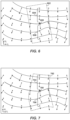
- Fig. 7 illustrates an adaptive dip-steered operator in accordance with the present technological advancement.
- Fig. 7 is a map view and depicts various contours and dip vectors, wherein 704 indicates updip and 706 indicates downdip points.
- the dip-steered operator 702 is a not a rectangle with orientation inherited from the central computation location 700. Rather, in accordance with the present technological advancement, the adaptive dip-steered operator changes its geometry as it grows away from the central computation location point 700. The dip direction is followed laterally (and vertically) and is not assumed constant.
- Fig. 8 illustrates a conventional strike-steered operator definition.
- Fig. 8 is a map view and depicts various contours and dip vectors (strike vectors being perpendicular to the dip vectors), wherein 804 indicates updip and 806 indicates downdip.
- the strike-steered operator 802 is a rectangle centered a computation location 800.
- the orientation of the strike-steered operator 802 is inherited from the central computation location 800.
- Fig. 9 illustrates an adaptive strike-steered operator in accordance with the present technological advancement.
- Fig. 9 is a map view and depicts various contours and dip vectors (strike vectors being perpendicular to the dip vectors), wherein 904 indicates updip and 906 indicates downdip.
- the strike-steered operator 902 is a not a rectangle with orientation inherited from the central computation location 900. Rather, in accordance with the present technological advancement, the adaptive strike-steered operator 902 changes its geometry as it grows away from the central computation location point 900. The strike direction is followed laterally (and vertically) and is not assumed constant.
- Fig. 10 illustrates the same example shown in Figs. 6 and 7 , but in a side view.
- the "structure" is followed adaptively in the dip, strike and normal (strike not shown for graphing purposes) direction resulting in a truly structured adaptive operator.
- seismic data samples 1001 (only one being labeled for clarity) are shown in a vertical plane view.
- the adaptive structured oriented operated 1002 is centered at computation location 1000 and grown in a manner consistent with the present technological advancement as discussed above.
- the lines 1003 are seismically derived surfaces (as opposed to Figs. 6 and 7 , wherein the lines are contours on a 2D map view) for illustration purposes and are not used for growing the operator.
- the present technological advancement includes populating a large operator in one go, "growing" it from a central location and using the varying dip and/or strike lateral and vertical variations to adapt its geometry or shape.
- the exemplary embodiments in Figs. 7 , 9 , and 10 illustrate that the ASO changes its search direction at each data point of the operator, which makes the operator adaptive.
- ASO Using ASO versus a conventional structure guided operator allows a user to generate more locally accurate and refined results by eliminating the assumption that the structure direction is unique throughout the entire operator size.
- the shape of the ASO is solely guided by the variation of the input dip and azimuth fields, varies from computation location to the next, and is not fixed in XYZ space or simulated in a cascaded approach.
- the ASO size is the same in dip/strike/Normal space for each computation point, but varies in the XYZ space depending upon the input dip and azimuth cubes.
- the computation of the ASO can be done in one pass (i.e. does not require running multiple iterations) and can fully utilize the lateral and vertical variations of dip and azimuth, namely the "structure" of the seismic data.
- hydrocarbon management includes acquiring seismic data, hydrocarbon extraction, hydrocarbon production, hydrocarbon exploration, identifying potential hydrocarbon resources, identifying well locations, drilling a well, determining well injection and/or extraction rates, identifying reservoir connectivity, acquiring, disposing of and/or abandoning hydrocarbon resources, reviewing prior hydrocarbon management decisions, and any other hydrocarbon-related acts or activities.
- Fig. 11 is a block diagram of a computer system 2400 that can be used to generate the ASO.
- a central processing unit (CPU) 2402 is coupled to system bus 2404.
- the CPU 2402 may be any general- purpose CPU, although other types of architectures of CPU 2402 (or other components of exemplary system 2400) may be used as long as CPU 2402 (and other components of system 2400) supports the operations as described herein.
- Those of ordinary skill in the art will appreciate that, while only a single CPU 2402 is shown in Fig. 11 , additional CPUs may be present.
- the computer system 2400 may comprise a networked, multi-processor computer system that may include a hybrid parallel CPU/GPU system.
- the CPU 402 may execute the various logical instructions according to various teachings disclosed herein. For example, the CPU 2402 may execute machine-level instructions for performing processing according to the operational flow described.
- the computer system 2400 may also include computer components such as non-transitory, computer -readable media. Examples of computer -readable media include a random access memory (RAM) 2406, which may be SRAM, DRAM, SDRAM, or the like.
- RAM random access memory
- the computer system 2400 may also include additional non-transitory, computer -readable media such as a read-only memory (ROM) 2408, which may be PROM, EPROM, EEPROM, or the like.
- ROM read-only memory
- RAM 2406 and ROM 2408 hold user and system data and programs, as is known in the art.
- the computer system 2400 may also include an input/output (I/O) adapter 2410, a communications adapter 2422, a user interface adapter 2424, and a display adapter 2418.
- I/O input/output
- the I/O adapter 2410 may connect additional non-transitory, computer-readable media such as a storage device(s) 2412, including, for example, a hard drive, a compact disc (CD) drive, a floppy disk drive, a tape drive, and the like to computer system 2400.
- a storage device(s) 2412 including, for example, a hard drive, a compact disc (CD) drive, a floppy disk drive, a tape drive, and the like to computer system 2400.
- the storage device(s) may be used when RAM 2406 is insufficient for the memory requirements associated with storing data for operations of the present techniques.
- the data storage of the computer system 2400 may be used for storing information and/or other data used or generated as disclosed herein.
- storage device(s) 2412 may be used to store configuration information or additional plug-ins in accordance with the present techniques.
- user interface adapter 2424 couples user input devices, such as a keyboard 2428, a pointing device 2426 and/or output devices to the computer system 400.
- the display adapter 2418 is driven by the CPU 2402 to control the display on a display device 2420 to, for example, present information to the user regarding available plug-ins.
- the architecture of system 2400 may be varied as desired.
- any suitable processor-based device may be used, including without limitation personal computers, laptop computers, computer workstations, and multi-processor servers.
- the present technological advancement may be implemented on application specific integrated circuits (ASICs) or very large scale integrated (VLSI) circuits.
- ASICs application specific integrated circuits
- VLSI very large scale integrated circuits
- persons of ordinary skill in the art may use any number of suitable hardware structures capable of executing logical operations according to the present technological advancement.
- the term "processing circuit” encompasses a hardware processor (such as those found in the hardware devices noted above), ASICs, and VLSI circuits.
- Input data to the computer system 2400 may include various plug-ins and library files. Input data may additionally include configuration information.
Landscapes
- Engineering & Computer Science (AREA)
- Remote Sensing (AREA)
- Physics & Mathematics (AREA)
- Life Sciences & Earth Sciences (AREA)
- Acoustics & Sound (AREA)
- Environmental & Geological Engineering (AREA)
- Geology (AREA)
- General Life Sciences & Earth Sciences (AREA)
- General Physics & Mathematics (AREA)
- Geophysics (AREA)
- Geophysics And Detection Of Objects (AREA)
Description
- This application claims the benefit of
U.S. Provisional Patent Application 62/106,488 filed January 22, 2015 - This invention relates generally to the field of geophysical prospecting of data for potential hydrocarbon opportunities and, more particularly, to seismic data analysis. Exemplary embodiments described herein generally pertain to imaging subsurface geological layers. More specifically, exemplary embodiments described herein pertain to an adaptive dip-steered/azimuth-steered/normal-steered way of analyzing seismic data.
- This section is intended to introduce various aspects of the art, which may be associated with exemplary embodiments of the present invention. This discussion is believed to assist in providing a framework to facilitate a better understanding of particular aspects of the present invention. Accordingly, it should be understood that this section should be read in this light, and not necessarily as admissions of prior art.
- Seismic data are acquired and processed to help geoscientists visualize and quantify key metrics linked to detecting or assessing the quantity and quality of hydrocarbons potentially present in the subsurface. Seismic datasets are a way to "image" the subsurface geological layers in a way that geoscientists can interpret geological layers and morphologies. Geological layers are characterized by their rock physical, acoustical properties, direction of deposition or continuity, but also by their "structure": direction towards which layers are dipping toward at the current time. The "structure" is characterized by two principal measurements called dip and azimuth that define the exact direction layers are dipping towards in the subsurface. These measurements define the dip and strike direction for any point in the subsurface.
-
Fig. 1 illustrates dip and strike directions. The strike direction of a geologicalplanar feature 100 is aline 102 representing the intersection of thatfeature 100 with ahorizontal plane 104. The strike direction is usually referred to as the "azimuth" or angle, in a horizontal plane, between thestrike line 102 and a reference direction (i.e., north or a specified direction like the survey main axis). Thedip vector feature 106 is vector which has the steepest angle (relative to the horizontal plane 104) of descent within the sameplanar feature 100 Dip and strike directions are perpendicular to one another. The dip vector is characterized by its dip and also its dip azimuth which is the direction the dip vector points towards. The dip vector azimuth is 90 degrees rotated compared to the "azimuth" of theplanar feature 100. In this paper, the "dip direction" is the direction the dip vector is pointing towards and the "strike direction" is thehorizontal vector feature 102. - The third direction commonly used is the normal to the geological layer and is defined by the vector perpendicular to the plane defined by the dip and strike vectors (i.e. planar feature 100).
Fig. 2 illustrates a normal vector to a given surface (from Oleg Alexandrov, 2011). For a given surface, the strike and dip direction define a dip-azimuth plane 200. Thenormal vector 202 to thesurface 204 is the vector perpendicular to the dip-azimuth plane 200. - Extracting valuable information from seismic data, especially three-dimensional (3D) seismic data, can be based on algorithms (or mathematical operations) that use operators in XYZ space. An operator is a way to select in the XYZ or INLINE/CROSSLINE/Z seismic sample points to run operations on.
- A classic way of extracting information from seismic data is to use structure guided image processing applied to seismic data. The structure dip and strike directions can be computed in several ways resulting in dip and azimuth data cubes of the same footprint as the seismic data they are computed on (
Fig. 1 ). In order to better relate seismic data measurements to geology, the classic approach in operator design is to use a structure guided operator; namely "dip-steered" or "strike-steered" operator. - The current standard in the industry is to use dip and azimuth (
Figure 1 and 2 ) to guide the operator direction in two fashions. The first, for a large operator, the operator direction is either kept constant, inheriting a single dip and azimuth from the computation location for the entire operator (Figs. 5 and7 ). The operator is called "Linear" or local because it uses a unique direction computed at the center of the operator. The major flaw with these approaches is that the lateral variation of dip and strike directions are not fully taken into account. The second is using a cascaded approach where a small operator is run on the data multiple times, recursively, with each iteration's result becoming the input for the next iteration. The cascaded approach fully utilizes the lateral variation of dip and strike, generating the results of a larger operator without the requirement of explicitly populating the larger operator, but requires running multiple times. - For conventional methods, the resulting data point selection by the operator may include data points that are not intended to be selected or miss relevant others.
- A technical problem exists in regards to how to properly design the operator using dip and strike direction data to have a meaningful operation result. Trying to select data points in the strike or dip direction would requires an operator that changes direction as it expands away from the central computation location, because dip and strike direction are not the same from point to point. This has not been previously done in the industry.
- Further background information can be found in Nonlinear structure-enhancing filtering using plane-wave prediction, Liu et al., Geophysical Prospecting, 2010, 58, 415-427; and Structure-oriented smoothing and semblance, Hale, Center for Wave Phenomena, Colorado School of Mines.
-
US6735526B1 discloses a method of combining directional seismic attributes using a supervised learning approach which may include extracting seismic information from acquired data in a direction along the spatial direction of a body of interest. The method is applicable to both onshore nad offshore exploration and provides a more reliable means of detecting, separating and identifying geological features, for example gas chimneys, faults, layers, and any other type of geological objects with a spatial direction and shape. The method is also suited for the detection of reservoir changes by the use of time lapse seismic techniques. - Paul de Groot et al., 'How to create and use 3D Wheeler transformed seismic volumes' SEG/New Orleans 2006 Annual Meeting (2006) pages 1038-1042, discuss interpreting seismic data in the Wheeler transformed domain. In this domain seismic data or derived attributes are flattened along chrono-stratigraphic lines whilst truncations and non-depositional/erosional hiatuses are honoured. A data-driven chrono-stratigraphic assignment algorithm that is used to flatten the data is explained. Sequence stratigraphic interpretation on how chrono-stratigraphy and lap-out patterns are used to perform sysem tracts interpretation is discussed, and previous of sequence stratigraphic interpretation techniques that are under development is given.
-
CN103412331A discloses an automatic extraction method for a three-dimensional earthquake fault. The method comprises subjecting data to image division. Initial clustering is carried out on a fault by using the space-grid distance properties of fault data points. Further classification of the fault is carried out on the fault obtained using initial clustering, by using the dip angle property of the fault. Fault surfaces are then obtained, which are independent and uncrossed. The method allows automatic identification of fault surfaces to be carried out, addressing difficulties associated with subjectivity of known methods. -
US2006/122780A discloses a method and apparatus for seismic image processing. An embodiment aids identification of subterranean faults, which are significant in hydrocarbon exploration. The method includes steps of: (a) reading a three dimensional seismic data volume; (b) computing the three dimensional orientation of the subsurface; (c) subdividing the original volume into smaller data volumes that are rotated at a pre-determined set of dips and azimuths related to those of the subsurface orientation volume; (d) performing a 3D contrast enhancement operation in each of the smaller volumes; (e) filtering the result of the contrast enhahcement with selected 3D filters at the pre-determined sets of dips and azimuths; (f) skeletonizing the results of the filtering operation; (g) separating the individual fault surfaces; and (h) labelling the individual fault surfaces for further interpretation and exploration. - The present invention pertains to a method as described in the
independent claim 1. Further advantages of the method are presented in the dependent claims. - In the method, the growing can include following a predetermined priority from amongst a dip direction following a dip vector direction, a strike direction following an azimuth vector direction, and a normal vector perpendicular to both the dip and azimuth vectors.
- In the method, the adaptive structure-oriented operator can be a same size in dip/strike/Normal space for each computation point in the seismic data, but varies in x, y, z, space.
- The method can further include: performing an operation on the seismic data sample within the adaptive structure-oriented operator to generate modified seismic data; and performing hydrocarbon management based on the modified seismic data.
- In the method, the seismic data sample points can be regularly sampled.
- While the present disclosure is susceptible to various modifications and alternative forms, specific example embodiments thereof have been shown in the drawings and are herein described in detail. It should be understood, however, that the description herein of specific example embodiments is not intended to limit the disclosure to the particular forms disclosed herein, but on the contrary, this disclosure is to cover all modifications and equivalents as defined by the appended claims. It should also be understood that the drawings are not necessarily to scale, emphasis instead being placed upon clearly illustrating principles of exemplary embodiments of the present invention. Moreover, certain dimensions may be exaggerated to help visually convey such principles.
-
Fig. 1 illustrates the concepts of strike and dip. -
Fig. 2 illustrates a normal vector to a given surface. -
Fig. 3 is an exemplary method of generating an adaptive structure-oriented operator. -
Fig. 4 is an exemplary map view of seismic data locations. -
Fig. 5 is a map view of dip and strike vector computation results from seismic data. -
Fig. 6 illustrates a map view of a conventional dip-steered operator. -
Fig. 7 illustrates a map view of an adaptive dip-steered operator. -
Fig. 8 illustrates a map view of a conventional strike-steered operator. -
Fig. 9 illustrates a map view of an adaptive strike-steered operator. -
Fig. 10 illustrates a 2D side (or vertical) view of an adaptive structure oriented steered operator. -
Fig. 11 illustrates a computer system. - Exemplary embodiments are described herein. However, to the extent that the following description is specific to a particular, this is intended to be for exemplary purposes only and simply provides a description of the exemplary embodiments. Accordingly, the invention is not limited to the specific embodiments described below, but rather, it includes all alternatives, modifications, and equivalents falling within the scope of the appended claims.
- The "Adaptive" Structure-oriented Operator (ASO) presented herein is a refinement to existing concepts of structure guided image processing applied to seismic data in order to better detect seismic amplitude features or enhance seismic data quality. The ASO is a way to select seismic data points using an operator or kernel defined in the dip/azimuth/normal to bed dip direction. In short, the ASO is a dip-steered and/or azimuth and/or normal-steered way of analyzing seismic data that is locally adaptive.
- The present technological advancement includes populating a large operator in one go; "growing" it from a central location and using the varying dip and strike lateral and vertical variations to adapt its geometry or shape. By "growing", it is implied that the operator is developed through the data cube using the structural dip and azimuth; this "growing" can be achieved by expanding a geobody using neighborhood cells, sliding planes or lines along one chosen dimension; or following dip, strike and normal direction vectors in a linear fashion in 3D using a chosen dimensional order (i.e. dip then strike then normal, strike then dip then normal, ...). The exemplary embodiments discussed herein explain how the ASO changes its search direction at each data point of the operator, which makes the operator adaptive.
- The present technological advancement can improve the ability to compute direct hydrocarbon indicators (DHI) attributes, such as Lateral Amplitude Contrast, Down Dip Terminations, and Amplitude Fit to Structure, for example, which are discussed in
U.S. Patent Application Publication 2014/0303896 (title: Method for Quantitative Definition of Direct Hydrocarbon Indicators). Applications of the present ASO technique include, but are not necessarily limited thereto, seismic amplitude feature detection, seismic data labeling, and seismic data enhancement (de-noising). Moreover, the present technological advancement can be used to create improved images of the subsurface, and can be used in the exploration and recovery of hydrocarbons. -
Fig. 3 illustrates an exemplary method embodying the present technological advancement. The ASO is a better way to properly find points belonging to a structure-oriented 3D operator of a given geometry in the dip, strike, and normal space. - In
step 301, input data is obtained. The input data is either 2D or 3D cubes of seismic data, along with corresponding dip and azimuth data. A seismic cube can have any type of geometry. A dip cube, usually in degrees, is computed on a same geometry as the seismic cube. An azimuth cube, usually in degrees, is computed on a same geometry as the seismic cube, with an angle defined from the XLINE direction (using, Petrel® for example) and not the true North direction. For dip and azimuth in Petrel®, it is assumed that the input cube of seismic data has a cell of the same dimension in each direction (pixel mode). Vector computations are done independently from seismic cell dimensions. In Petrel®, dip and azimuth angles are computed in the pixel space, not the XYZ space. -
Fig. 4 is a map view (or top view) of 3Dseismic data locations 401. Thedata locations 401 are regularly sampled seismic locations that can be used as computation locations. However, irregular sampling can also be used (i.e. 2D datasets). -
Fig. 5 is a map view of the 3Dseismic data locations 401 with the strike vectors (solid) and dip vectors (dashed) displayed for the corresponding regularly sampled seismic data locations. The dashed dip vectors show the direction the geological bed dips; wherein the longer the dip vector the steeper the bed. The solid strike vectors show the strike direction and have the same length (zero dip). - In
step 303, user defined operator size or reach is obtained. The user can define the radius in the dip direction (Rdip), radius in the strike direction (Rstrike), and the radius in the normal direction (Rnorm). This will control the size of the ASO. - In
step 305, the dip and azimuth are converted to dI, dJ and dK displacement vector coordinates on the XL (crossline), IL (inline), and Z axis, respectively. This is accomplished by computing the projection INLINE, CROSSLINE, and Z axis for the dip and normal vectors. This allows for translating the dip and azimuth input values into discrete steps in all seismic axes for each input sample. - The V vector quantifies the amount of projected distance covered in INLINE, CROSSLINE and Z axis respectively for each step in the dip direction.


- The S1 and S2 vectors quantify the amount of projected distance covered in INLINE, CROSSLINE and Z axis respectively for each step in the strike direction.

- The N vector quantifies the amount of projected distance covered in INLINE, CROSSLINE and Z axis respectively for each step in the NORMAL direction.


- In
step 307, the adaptive structured-oriented operators are created and structure-oriented 3D neighbors (I, J, K) are determined. This step includes finding, within the seismic data, all the neighbors from a central computation location (700 inFig. 7 or 900 inFig. 9 ) that are reached by the ASO. Using V, S1, S2, and N, neighboring samples n are found by growing the operator from a central computation point in the normal, strike, and/or dip directions. The number of samples n within the ASO is determined by equation 6.
- There are many ways of growing the operator. For instance one can define priorities, dip direction first from center location as first step, then strike direction from
step 1 points as second step and finally normal direction from points grown insteps - In
step 309, the seismic amplitudes for the n samples selected by the ASO are read, "populating" the operator. This step can involve reading the amplitudes of the closest nodes (no interpolation, also called "snapping") or interpolate the input seismic amplitudes to the non-discrete INLINE, CROSSLINE and Z axis values calculated by the ASO. Interpolation can be done using various interpolation schemes, dip-steered and azimuth-steered or not. - In
step 311, a user defined operation is performed on the n amplitude points populated instep 309. Such user defined operations can include determination of median, average, or count, comparing a plurality of the n amplitude points to each other or some other data, performing amplitude edge detection, conformance to structure, signal enhancement, or denoising. Moreover, the n amplitude points can be used to construct an image of the subsurface. This is not an exhaustive list as a user could determine other operations to perform on the n amplitude points. Those of ordinary skill in the art are familiar with the operations that can be carried out on selected samples. The present technological advancement relates to the ASO that properly selects samples using structure dip and/or azimuth measurements as a guide. - In
step 313, if additional input cube samples are available, then the process can return to step 307 and a new ASO can be formed for the additional input cube sample. Each new ASO is generated independently of other operators, as the present technological advancement is not a cascaded process. - If there are no more additional input cube samples, then the process can proceed to step 315, wherein a new seismic cube is outputted constructing a new image of the subsurface.
- For comparison purposes.
Fig. 6 illustrates a conventional dip-steered operator definition.Fig. 6 is a map view and depicts various contours and dip vectors, wherein 604 indicates updip and 606 indicates downdip. The dip-steeredoperator 602 is a rectangle centered acomputation location 600. The orientation of the dip-steeredoperator 602 is inherited from thecentral computation location 600. -
Fig. 7 illustrates an adaptive dip-steered operator in accordance with the present technological advancement.Fig. 7 is a map view and depicts various contours and dip vectors, wherein 704 indicates updip and 706 indicates downdip points. The dip-steeredoperator 702 is a not a rectangle with orientation inherited from thecentral computation location 700. Rather, in accordance with the present technological advancement, the adaptive dip-steered operator changes its geometry as it grows away from the centralcomputation location point 700. The dip direction is followed laterally (and vertically) and is not assumed constant. - For comparison purposes.
Fig. 8 illustrates a conventional strike-steered operator definition.Fig. 8 is a map view and depicts various contours and dip vectors (strike vectors being perpendicular to the dip vectors), wherein 804 indicates updip and 806 indicates downdip. The strike-steeredoperator 802 is a rectangle centered acomputation location 800. The orientation of the strike-steeredoperator 802 is inherited from thecentral computation location 800. -
Fig. 9 illustrates an adaptive strike-steered operator in accordance with the present technological advancement.Fig. 9 is a map view and depicts various contours and dip vectors (strike vectors being perpendicular to the dip vectors), wherein 904 indicates updip and 906 indicates downdip. The strike-steeredoperator 902 is a not a rectangle with orientation inherited from thecentral computation location 900. Rather, in accordance with the present technological advancement, the adaptive strike-steeredoperator 902 changes its geometry as it grows away from the centralcomputation location point 900. The strike direction is followed laterally (and vertically) and is not assumed constant. -
Fig. 10 illustrates the same example shown inFigs. 6 and 7 , but in a side view. The "structure" is followed adaptively in the dip, strike and normal (strike not shown for graphing purposes) direction resulting in a truly structured adaptive operator. InFig. 10 , seismic data samples 1001 (only one being labeled for clarity) are shown in a vertical plane view. The adaptive structured oriented operated 1002 is centered atcomputation location 1000 and grown in a manner consistent with the present technological advancement as discussed above. AsFig. 10 is a vertical plane view, thelines 1003 are seismically derived surfaces (as opposed toFigs. 6 and 7 , wherein the lines are contours on a 2D map view) for illustration purposes and are not used for growing the operator. - The present technological advancement includes populating a large operator in one go, "growing" it from a central location and using the varying dip and/or strike lateral and vertical variations to adapt its geometry or shape. The exemplary embodiments in
Figs. 7 ,9 , and10 illustrate that the ASO changes its search direction at each data point of the operator, which makes the operator adaptive. - Comparing
Figure 6 to 9 andFigure 10 , those of ordinary skill in the art can appreciate why such an adaptive operator design is superior to classic approaches and shows data selected by the adaptive operator are the points intended to be captured by "dip-steered" or "strike-steered" operator in the first place. TheFigures 6-9 show a 2D map view example for simplicity, but the normal to bed dip (Fig. 2 ) is also followed adaptively by the ASO. The structure direction (dip and azimuth) used by the ASO is NOT being recomputed during the process (i.e., the process inFig. 3 does not need to recompute the structure direction as the ASO is adaptive and possesses the structure direction as input data (dip and azimuth cubes)). - Using ASO versus a conventional structure guided operator allows a user to generate more locally accurate and refined results by eliminating the assumption that the structure direction is unique throughout the entire operator size. The shape of the ASO is solely guided by the variation of the input dip and azimuth fields, varies from computation location to the next, and is not fixed in XYZ space or simulated in a cascaded approach. In the present technological advancement, the ASO size is the same in dip/strike/Normal space for each computation point, but varies in the XYZ space depending upon the input dip and azimuth cubes. The computation of the ASO can be done in one pass (i.e. does not require running multiple iterations) and can fully utilize the lateral and vertical variations of dip and azimuth, namely the "structure" of the seismic data.
- Furthermore, the new seismic cube created by the present technological advancement can be used to manage hydrocarbons. As used herein, hydrocarbon management includes acquiring seismic data, hydrocarbon extraction, hydrocarbon production, hydrocarbon exploration, identifying potential hydrocarbon resources, identifying well locations, drilling a well, determining well injection and/or extraction rates, identifying reservoir connectivity, acquiring, disposing of and/or abandoning hydrocarbon resources, reviewing prior hydrocarbon management decisions, and any other hydrocarbon-related acts or activities.
-
Fig. 11 is a block diagram of acomputer system 2400 that can be used to generate the ASO. A central processing unit (CPU) 2402 is coupled tosystem bus 2404. TheCPU 2402 may be any general- purpose CPU, although other types of architectures of CPU 2402 (or other components of exemplary system 2400) may be used as long as CPU 2402 (and other components of system 2400) supports the operations as described herein. Those of ordinary skill in the art will appreciate that, while only asingle CPU 2402 is shown inFig. 11 , additional CPUs may be present. Moreover, thecomputer system 2400 may comprise a networked, multi-processor computer system that may include a hybrid parallel CPU/GPU system. The CPU 402 may execute the various logical instructions according to various teachings disclosed herein. For example, theCPU 2402 may execute machine-level instructions for performing processing according to the operational flow described. - The
computer system 2400 may also include computer components such as non-transitory, computer -readable media. Examples of computer -readable media include a random access memory (RAM) 2406, which may be SRAM, DRAM, SDRAM, or the like. Thecomputer system 2400 may also include additional non-transitory, computer -readable media such as a read-only memory (ROM) 2408, which may be PROM, EPROM, EEPROM, or the like.RAM 2406 andROM 2408 hold user and system data and programs, as is known in the art. Thecomputer system 2400 may also include an input/output (I/O)adapter 2410, acommunications adapter 2422, auser interface adapter 2424, and adisplay adapter 2418. - The I/
O adapter 2410 may connect additional non-transitory, computer-readable media such as a storage device(s) 2412, including, for example, a hard drive, a compact disc (CD) drive, a floppy disk drive, a tape drive, and the like tocomputer system 2400. The storage device(s) may be used whenRAM 2406 is insufficient for the memory requirements associated with storing data for operations of the present techniques. The data storage of thecomputer system 2400 may be used for storing information and/or other data used or generated as disclosed herein. For example, storage device(s) 2412 may be used to store configuration information or additional plug-ins in accordance with the present techniques. Further,user interface adapter 2424 couples user input devices, such as akeyboard 2428, apointing device 2426 and/or output devices to the computer system 400. Thedisplay adapter 2418 is driven by theCPU 2402 to control the display on adisplay device 2420 to, for example, present information to the user regarding available plug-ins. - The architecture of
system 2400 may be varied as desired. For example, any suitable processor-based device may be used, including without limitation personal computers, laptop computers, computer workstations, and multi-processor servers. Moreover, the present technological advancement may be implemented on application specific integrated circuits (ASICs) or very large scale integrated (VLSI) circuits. In fact, persons of ordinary skill in the art may use any number of suitable hardware structures capable of executing logical operations according to the present technological advancement. The term "processing circuit" encompasses a hardware processor (such as those found in the hardware devices noted above), ASICs, and VLSI circuits. Input data to thecomputer system 2400 may include various plug-ins and library files. Input data may additionally include configuration information. - The present techniques may be susceptible to various modifications and alternative forms, and the examples discussed above have been shown only by way of example. However, the present techni ques are not intended to be limited to the particular examples disclosed herein. Indeed, the present techniques include all alternatives, modifications, and equivalents falling within the scope of the appended claims.
Claims (9)
- A method, comprising:obtaining input data (301) as 2D seismic data or 3D cubes of seismic data from data sampling locations from a seismic survey, along with corresponding dip and azimuth data of a geological layer;selecting a data sampling location as a central computation location,defining an operator size (303) for an adaptive structure-oriented operator (ASO) to be created, respectively in a dip direction (Rdip), strike direction (Rstrike) and normal direction (Rnorm);converting (305) the dip and azimuth data of the data sampling locations to displacement vector coordinates projected on the crossline (XL), inline (IL), and Z axis, and translating the dip and azimuth data into discrete steps for each input sample;determining a normalized dip vector (V), representing a projected distance covered on the crossline (XL), inline (IL) and Z axis for each step in the dip direction;determining normalized strike vectors (S1, S2), representing a projected distance covered on the crossline (XL), inline (IL) and Z axis for each step in the strike direction;determining normal vector (N), representing a projected distance covered on the crossline (XL), inline (IL) and Z axis for each step in the normal direction;creating (307), with a computer, an adaptive structure-oriented operator (ASO) for the central computational location;wherein creating the adaptive structure-oriented operator, comprises:- starting from the central computational location, selecting neighboring samples (n) in the normal, strike and dip direction by using the determined normalized dip vector (V), normalized strike vectors (S1, S2) and normal vector (N);- starting from one or more of the selected neighboring samples (n), selecting new neighboring samples (n) in the normal, strike and dip direction by using the determined normalized dip vector (V), normalized strike vectors (S1, S2) and normal vector (N);- stopping to select neighboring samples when the samples distance from the central computational location corresponds to the defined size for the operator respectively in the dip direction (Rdip), strike direction (Rstrike), and normal direction (Rnorm);populating (309) the operator by associating to each of the selected samples (n) a corresponding amplitude from the seismic input data;construct an image of a subsurface using the amplitude values from the seismic input data associated to the operator;using the constructed image of a subsurface in exploration and recovery of hydrocarbons.
- The method of any preceding claim, wherein the creating includes following a predetermined priority from amongst a dip direction following a dip vector direction, a strike vector following an strike direction, and a normal vector direction perpendicular to both dip and strike vectors.
- The method of any preceding claim, further comprising: creating the adaptive structure-oriented operator in a strike direction or a dip direction until a predetermined radius in the strike direction or dip direction, respectively, is reached.
- The method of any preceding claim wherein the adaptive structure-oriented operator is a same size in dip/strike/Normal space for each computation point in the seismic data, but varies in x, y, z, space.
- The method of any preceding claim, further comprising:performing an operation on the seismic data sample within the adaptive structure-oriented operator to generate modified seismic data; andperforming hydrocarbon management based on the modified seismic data.
- The method of any preceding claim, wherein the seismic data sample points are regularly sampled.
- The method of claim 5, further comprising generating an image of a subsurface region using the modified seismic data.
- The method of any preceding claim, wherein the creating includes expanding a geobody using neighboring cells.
- The method of any preceding claim, wherein the creating includes sliding a plane along a chosen dimension.
Applications Claiming Priority (2)
| Application Number | Priority Date | Filing Date | Title |
|---|---|---|---|
| US201562106488P | 2015-01-22 | 2015-01-22 | |
| PCT/US2015/061266 WO2016118223A1 (en) | 2015-01-22 | 2015-11-18 | Adaptive structure-oriented operator |
Publications (2)
| Publication Number | Publication Date |
|---|---|
| EP3248030A1 EP3248030A1 (en) | 2017-11-29 |
| EP3248030B1 true EP3248030B1 (en) | 2024-09-11 |
Family
ID=54705907
Family Applications (1)
| Application Number | Title | Priority Date | Filing Date |
|---|---|---|---|
| EP15801643.6A Active EP3248030B1 (en) | 2015-01-22 | 2015-11-18 | Adaptive structure-oriented operator |
Country Status (3)
| Country | Link |
|---|---|
| US (1) | US10082588B2 (en) |
| EP (1) | EP3248030B1 (en) |
| WO (1) | WO2016118223A1 (en) |
Families Citing this family (3)
| Publication number | Priority date | Publication date | Assignee | Title |
|---|---|---|---|---|
| US10996358B2 (en) | 2017-08-18 | 2021-05-04 | Saudi Arabian Oil Company | Image-guided velocity interpolation using a mask cube |
| CN115561808A (en) * | 2021-07-02 | 2023-01-03 | 中国石油天然气股份有限公司 | Method, device and storage medium for improving seismic fault identification accuracy |
| US11754665B2 (en) | 2021-08-13 | 2023-09-12 | Qualcomm Incorporated | Handling positioning sessions during cell timing source outages |
Family Cites Families (108)
| Publication number | Priority date | Publication date | Assignee | Title |
|---|---|---|---|---|
| US4916615A (en) | 1986-07-14 | 1990-04-10 | Conoco Inc. | Method for stratigraphic correlation and reflection character analysis of setsmic signals |
| US5047991A (en) | 1989-04-28 | 1991-09-10 | Schlumberger Technology Corporation | Lithology identification using sonic data |
| US4992995A (en) | 1989-10-24 | 1991-02-12 | Amoco Corporation | Methods for attenuating noise in seismic data |
| US5274714A (en) | 1990-06-04 | 1993-12-28 | Neuristics, Inc. | Method and apparatus for determining and organizing feature vectors for neural network recognition |
| US5265192A (en) | 1990-09-20 | 1993-11-23 | Atlantic Richfield Company | Method for the automated editing of seismic traces using an adaptive network |
| US5444619A (en) | 1993-09-27 | 1995-08-22 | Schlumberger Technology Corporation | System and method of predicting reservoir properties |
| US5416750A (en) | 1994-03-25 | 1995-05-16 | Western Atlas International, Inc. | Bayesian sequential indicator simulation of lithology from seismic data |
| GB2322704B (en) | 1994-07-07 | 1998-12-09 | Geco As | Method of Processing seismic data |
| US5586082A (en) | 1995-03-02 | 1996-12-17 | The Trustees Of Columbia University In The City Of New York | Method for identifying subsurface fluid migration and drainage pathways in and among oil and gas reservoirs using 3-D and 4-D seismic imaging |
| US5539704A (en) | 1995-06-23 | 1996-07-23 | Western Atlas International, Inc. | Bayesian sequential Gaussian simulation of lithology with non-linear data |
| FR2738920B1 (en) | 1995-09-19 | 1997-11-14 | Elf Aquitaine | METHOD FOR AUTOMATIC SEISMIC FACIAL RECOGNITION |
| US6052650A (en) | 1997-02-27 | 2000-04-18 | Schlumberger Technology Corporation | Enforcing consistency in geoscience models |
| US6466923B1 (en) | 1997-05-12 | 2002-10-15 | Chroma Graphics, Inc. | Method and apparatus for biomathematical pattern recognition |
| GB9904101D0 (en) | 1998-06-09 | 1999-04-14 | Geco As | Subsurface structure identification method |
| GB9819910D0 (en) * | 1998-09-11 | 1998-11-04 | Norske Stats Oljeselskap | Method of seismic signal processing |
| US6574565B1 (en) | 1998-09-15 | 2003-06-03 | Ronald R. Bush | System and method for enhanced hydrocarbon recovery |
| US6236942B1 (en) | 1998-09-15 | 2001-05-22 | Scientific Prediction Incorporated | System and method for delineating spatially dependent objects, such as hydrocarbon accumulations from seismic data |
| US6882997B1 (en) | 1999-08-25 | 2005-04-19 | The Research Foundation Of Suny At Buffalo | Wavelet-based clustering method for managing spatial data in very large databases |
| DE19943325C2 (en) | 1999-09-10 | 2001-12-13 | Trappe Henning | Process for processing seismic measurement data with a neural network |
| US6295504B1 (en) | 1999-10-25 | 2001-09-25 | Halliburton Energy Services, Inc. | Multi-resolution graph-based clustering |
| US6226596B1 (en) | 1999-10-27 | 2001-05-01 | Marathon Oil Company | Method for analyzing and classifying three dimensional seismic information |
| US6574566B2 (en) | 1999-12-27 | 2003-06-03 | Conocophillips Company | Automated feature identification in data displays |
| FR2808336B1 (en) | 2000-04-26 | 2002-06-07 | Elf Exploration Prod | METHOD OF CHRONO-STRATIGRAPHIC INTERPRETATION OF A SEISMIC SECTION OR BLOCK |
| US6363327B1 (en) | 2000-05-02 | 2002-03-26 | Chroma Graphics, Inc. | Method and apparatus for extracting selected feature information and classifying heterogeneous regions of N-dimensional spatial data |
| US6618678B1 (en) | 2000-05-26 | 2003-09-09 | Jason Geosystems B.V. | Method of joint analysis and interpretation of the subsurface from multiple seismic derived layer property data sets |
| US6625541B1 (en) | 2000-06-12 | 2003-09-23 | Schlumberger Technology Corporation | Methods for downhole waveform tracking and sonic labeling |
| FR2813959B1 (en) | 2000-09-11 | 2002-12-13 | Inst Francais Du Petrole | METHOD FOR FACILITATING THE RECOGNITION OF OBJECTS, IN PARTICULAR GEOLOGICAL OBJECTS, BY A DISCRIMINATING ANALYSIS TECHNIQUE |
| US6950786B1 (en) | 2000-10-10 | 2005-09-27 | Schlumberger Technology Corporation | Method and apparatus for generating a cross plot in attribute space from a plurality of attribute data sets and generating a class data set from the cross plot |
| US7006085B1 (en) | 2000-10-30 | 2006-02-28 | Magic Earth, Inc. | System and method for analyzing and imaging three-dimensional volume data sets |
| CA2432095C (en) | 2000-12-18 | 2010-04-13 | Randolph E. F. Pepper | Seismic signal processing method and apparatus for generating correlation spectral volumes to determine geologic features |
| US7203342B2 (en) | 2001-03-07 | 2007-04-10 | Schlumberger Technology Corporation | Image feature extraction |
| US6473696B1 (en) | 2001-03-13 | 2002-10-29 | Conoco Inc. | Method and process for prediction of subsurface fluid and rock pressures in the earth |
| US6751558B2 (en) | 2001-03-13 | 2004-06-15 | Conoco Inc. | Method and process for prediction of subsurface fluid and rock pressures in the earth |
| FR2824148B1 (en) | 2001-04-30 | 2003-09-12 | Inst Francais Du Petrole | METHOD FOR FACILITATING TRACKING OVER TIME OF THE DEVELOPMENT OF PHYSICAL STATES IN A SUBTERRANEAN FORMATION |
| DE10142785C2 (en) | 2001-08-31 | 2003-07-03 | Henning Trappe | Method for determining local similarity from 3D seismic measurement data |
| US6957146B1 (en) | 2001-12-24 | 2005-10-18 | Rdsp I, L.P. | System for utilizing seismic data to estimate subsurface lithology |
| FR2841344B1 (en) | 2002-06-19 | 2005-04-29 | Tsurf | METHOD, DEVICE AND PROGRAM PRODUCT FOR SMOOTHING SUBSURFACE PROPERTY |
| US7308139B2 (en) | 2002-07-12 | 2007-12-11 | Chroma Energy, Inc. | Method, system, and apparatus for color representation of seismic data and associated measurements |
| US7184991B1 (en) * | 2002-07-12 | 2007-02-27 | Chroma Energy, Inc. | Pattern recognition applied to oil exploration and production |
| US20050288863A1 (en) | 2002-07-12 | 2005-12-29 | Chroma Energy, Inc. | Method and system for utilizing string-length ratio in seismic analysis |
| US7162463B1 (en) | 2002-07-12 | 2007-01-09 | Chroma Energy, Inc. | Pattern recognition template construction applied to oil exploration and production |
| US7188092B2 (en) | 2002-07-12 | 2007-03-06 | Chroma Energy, Inc. | Pattern recognition template application applied to oil exploration and production |
| US7295706B2 (en) | 2002-07-12 | 2007-11-13 | Chroma Group, Inc. | Pattern recognition applied to graphic imaging |
| US20060184488A1 (en) | 2002-07-12 | 2006-08-17 | Chroma Energy, Inc. | Method and system for trace aligned and trace non-aligned pattern statistical calculation in seismic analysis |
| GB2394050B (en) | 2002-10-07 | 2005-11-23 | Westerngeco Seismic Holdings | Processing seismic data |
| WO2004044615A2 (en) | 2002-11-09 | 2004-05-27 | Geoenergy, Inc. | Method and apparatus for seismic feature extraction |
| US7053131B2 (en) | 2002-12-03 | 2006-05-30 | Kimberly-Clark Worldwide, Inc. | Absorbent articles comprising supercritical fluid treated HIPE, I-HIPE foams and other foams |
| US7206782B1 (en) | 2003-01-29 | 2007-04-17 | Michael John Padgett | Method for deriving a GrAZ seismic attribute file |
| US6754380B1 (en) | 2003-02-14 | 2004-06-22 | The University Of Chicago | Method of training massive training artificial neural networks (MTANN) for the detection of abnormalities in medical images |
| GB2400664B (en) | 2003-04-10 | 2005-05-25 | Schlumberger Holdings | Extrema classification |
| US6804609B1 (en) | 2003-04-14 | 2004-10-12 | Conocophillips Company | Property prediction using residual stepwise regression |
| US6970397B2 (en) | 2003-07-09 | 2005-11-29 | Gas Technology Institute | Determination of fluid properties of earth formations using stochastic inversion |
| GB0318827D0 (en) | 2003-08-11 | 2003-09-10 | Bg Intellectual Pty Ltd | Dip value in seismic images |
| US20080270033A1 (en) | 2003-08-19 | 2008-10-30 | Apex Spectral Technology, Inc. | Methods of hydrocarbon detection using spectral energy analysis |
| US7243029B2 (en) | 2003-08-19 | 2007-07-10 | Apex Spectral Technology, Inc. | Systems and methods of hydrocarbon detection using wavelet energy absorption analysis |
| US7092824B2 (en) | 2003-10-20 | 2006-08-15 | Ascend Geo Llp | Methods and systems for interactive investigation of geophysical data |
| US7453766B1 (en) | 2003-11-25 | 2008-11-18 | Michael John Padgett | Method for deriving 3D output volumes using summation along flat spot dip vectors |
| US7463552B1 (en) | 2003-11-25 | 2008-12-09 | Michael John Padgett | Method for deriving 3D output volumes using filters derived from flat spot direction vectors |
| US7697373B1 (en) | 2003-11-25 | 2010-04-13 | Michael John Padgett | Method for deriving 3D output volumes using dip vector analysis |
| US7266041B1 (en) | 2005-06-21 | 2007-09-04 | Michael John Padgett | Multi-attribute background relative scanning of 3D geophysical datasets for locally anomaluous data points |
| US7453767B1 (en) | 2003-11-25 | 2008-11-18 | Michael John Padgett | Method for deriving a 3D GRAZ seismic attribute file |
| US6941228B2 (en) | 2003-12-05 | 2005-09-06 | Schlumberger Technology Corporation | Method and system and program storage device for analyzing compressional 2D seismic data to identify zones of open natural fractures within rock formations |
| US20050171700A1 (en) | 2004-01-30 | 2005-08-04 | Chroma Energy, Inc. | Device and system for calculating 3D seismic classification features and process for geoprospecting material seams |
| US20060115145A1 (en) | 2004-11-30 | 2006-06-01 | Microsoft Corporation | Bayesian conditional random fields |
| US8363959B2 (en) | 2005-03-21 | 2013-01-29 | Yeda Research & Development Co. Ltd. | Detecting irregularities |
| FR2884636B1 (en) | 2005-04-15 | 2007-07-06 | Earth Resource Man Services Er | PR0CEDE OF HIERARCHICAL DETERMINATION OF COHERENT EVENTS IN AN IMAGE |
| US20070067040A1 (en) | 2005-09-02 | 2007-03-22 | Anova Corporation | Methods and apparatus for reconstructing the anulus fibrosus |
| CA2571094C (en) | 2005-12-13 | 2014-06-17 | Calgary Scientific Inc. | Local dominant wave-vector analysis of seismic data |
| US8625885B2 (en) | 2006-03-23 | 2014-01-07 | Intelliscience Corporation | Methods and systems for data analysis and feature recognition |
| CN101506686B (en) | 2006-06-21 | 2013-11-06 | 特拉斯帕克地球科学有限责任公司 | Interpretation of Geological Sedimentary Systems |
| WO2008025786A2 (en) | 2006-08-31 | 2008-03-06 | Shell Internationale Research Maatschappij B.V. | Interpreting a plurality of m-dimensional attribute vectors assigned to a plurality of locations in an n-dimensional interpretation space |
| DE102006050534B4 (en) | 2006-10-26 | 2013-12-12 | Airbus Operations Gmbh | Conduit system for an aircraft, in particular an aircraft |
| FR2909185B1 (en) | 2006-11-27 | 2009-01-09 | Inst Francais Du Petrole | METHOD OF STRATIGRAPHIC INTERPRETATION OF SEISMIC IMAGES |
| US9835743B2 (en) | 2006-11-28 | 2017-12-05 | Magnitude Spas | System and method for seismic pattern recognition |
| GB2444506C (en) | 2006-12-06 | 2010-01-06 | Schlumberger Holdings | Processing of stratigraphic data |
| US8346695B2 (en) | 2007-03-29 | 2013-01-01 | Schlumberger Technology Corporation | System and method for multiple volume segmentation |
| US7658202B2 (en) | 2007-05-08 | 2010-02-09 | Kohler Co. | Low-profile valve assembly |
| US8803878B2 (en) | 2008-03-28 | 2014-08-12 | Schlumberger Technology Corporation | Visualizing region growing in three dimensional voxel volumes |
| WO2009142872A1 (en) * | 2008-05-22 | 2009-11-26 | Exxonmobil Upstream Research Company | Seismic horizon skeletonization |
| CA2729806A1 (en) | 2008-07-01 | 2010-01-07 | Schlumberger Canada Limited | Effective hydrocarbon reservoir exploration decision making |
| GB2462460C (en) | 2008-08-06 | 2015-07-29 | Statoilhydro Asa | Interactive rendering of physical entities |
| US8903659B2 (en) | 2009-06-09 | 2014-12-02 | Shell Oil Company | Method for analysis seismic data with attribute functions |
| US8463551B2 (en) | 2009-11-17 | 2013-06-11 | Schlumberger Technology Corporation | Consistent dip estimation for seismic imaging |
| US8326542B2 (en) | 2009-11-19 | 2012-12-04 | International Business Machines Corporation | Method and system for retrieving seismic data from a seismic section in bitmap format |
| WO2011077300A2 (en) | 2009-12-23 | 2011-06-30 | Schlumberger Technology Bv | Processing of geological data |
| US8358561B2 (en) | 2010-04-13 | 2013-01-22 | Spectraseis Ag | Bayesian DHI for seismic data |
| US8380435B2 (en) | 2010-05-06 | 2013-02-19 | Exxonmobil Upstream Research Company | Windowed statistical analysis for anomaly detection in geophysical datasets |
| US9134443B2 (en) | 2010-05-14 | 2015-09-15 | Schlumberger Technology Corporation | Segment identification and classification using horizon structure |
| US8447525B2 (en) | 2010-07-29 | 2013-05-21 | Schlumberger Technology Corporation | Interactive structural restoration while interpreting seismic volumes for structure and stratigraphy |
| US8515678B2 (en) | 2010-07-29 | 2013-08-20 | Schlumberger Technology Corporation | Chrono-stratigraphic and tectono-stratigraphic interpretation on seismic volumes |
| US20120090001A1 (en) | 2010-10-07 | 2012-04-12 | Tzu-Chiang Yen | Apparatus having multimedia interface and network access management integrated therein |
| GB201022128D0 (en) | 2010-12-31 | 2011-02-02 | Foster Findlay Ass Ltd | Active contour segmentation |
| US8972195B2 (en) | 2011-01-31 | 2015-03-03 | Chevron U.S.A. Inc. | Extracting geologic information from multiple offset stacks and/or angle stacks |
| US8838391B2 (en) | 2011-01-31 | 2014-09-16 | Chevron U.S.A. Inc. | Extracting geologic information from multiple offset stacks and/or angle stacks |
| US9121968B2 (en) | 2011-01-31 | 2015-09-01 | Chevron U.S.A. Inc. | Extracting geologic information from multiple offset stacks and/or angle stacks |
| US8861309B2 (en) | 2011-01-31 | 2014-10-14 | Chevron U.S.A. Inc. | Exploitation of self-consistency and differences between volume images and interpreted spatial/volumetric context |
| US20120197613A1 (en) | 2011-01-31 | 2012-08-02 | Chevron U.S.A. Inc. | Exploitation of self-consistency and differences between volume images and interpreted spatial/volumetric context |
| US20120322037A1 (en) | 2011-06-19 | 2012-12-20 | Adrienne Raglin | Anomaly Detection Educational Process |
| US8954303B2 (en) | 2011-06-28 | 2015-02-10 | Chevron U.S.A. Inc. | System and method for generating a geostatistical model of a geological volume of interest that is constrained by a process-based model of the geological volume of interest |
| US8843353B2 (en) | 2011-08-25 | 2014-09-23 | Chevron U.S.A. Inc. | Hybrid deterministic-geostatistical earth model |
| US9128203B2 (en) | 2011-09-28 | 2015-09-08 | Saudi Arabian Oil Company | Reservoir properties prediction with least square support vector machine |
| US20140081613A1 (en) | 2011-11-01 | 2014-03-20 | Austin Geomodeling, Inc. | Method, system and computer readable medium for scenario mangement of dynamic, three-dimensional geological interpretation and modeling |
| US20130138350A1 (en) | 2011-11-24 | 2013-05-30 | Manoj Vallikkat Thachaparambil | Enhanced termination identification function based on dip field generated from surface data |
| WO2013081708A1 (en) | 2011-11-29 | 2013-06-06 | Exxonmobil Upstream Research Company | Method for quantitative definition of direct hydrocarbon indicators |
| US9261615B2 (en) | 2012-06-15 | 2016-02-16 | Exxonmobil Upstream Research Company | Seismic anomaly detection using double-windowed statistical analysis |
| WO2014116340A2 (en) | 2012-11-09 | 2014-07-31 | California Institute Of Technology | Automated feature analysis, comparison, and anomaly detection |
| CN103412331B (en) | 2013-08-30 | 2015-10-28 | 电子科技大学 | A kind of Automatic extraction method for three-dimensional earthquake fault |
| WO2015034759A1 (en) | 2013-09-04 | 2015-03-12 | Neural Id Llc | Pattern recognition system |
-
2015
- 2015-11-18 EP EP15801643.6A patent/EP3248030B1/en active Active
- 2015-11-18 US US14/944,575 patent/US10082588B2/en active Active
- 2015-11-18 WO PCT/US2015/061266 patent/WO2016118223A1/en not_active Ceased
Also Published As
| Publication number | Publication date |
|---|---|
| US20160216390A1 (en) | 2016-07-28 |
| EP3248030A1 (en) | 2017-11-29 |
| US10082588B2 (en) | 2018-09-25 |
| WO2016118223A1 (en) | 2016-07-28 |
Similar Documents
| Publication | Publication Date | Title |
|---|---|---|
| West et al. | Interactive seismic facies classification using textural attributes and neural networks | |
| Gao | Latest developments in seismic texture analysis for subsurface structure, facies, and reservoir characterization: A review | |
| AU2022283783B2 (en) | Fluid saturation model for petrophysical inversion | |
| Hoyes et al. | A review of “global” interpretation methods for automated 3D horizon picking | |
| EP4334758B1 (en) | Multi-task neural network for salt model building | |
| Gao et al. | Extreme curvature and extreme flexure analysis for fracture characterization from 3D seismic data: New analytical algorithms and geologic implications | |
| US20230161061A1 (en) | Structured representations of subsurface features for hydrocarbon system and geological reasoning | |
| Di et al. | Semi‐automatic fault/fracture interpretation based on seismic geometry analysis | |
| US11604298B2 (en) | Subsurface fault extraction using undirected graphs | |
| CN108508481B (en) | A kind of method, apparatus and system of longitudinal wave converted wave seismic data time match | |
| US20220011456A1 (en) | Generating a model for seismic velocities in a subsurface region using inversion with lateral variations | |
| Gu et al. | Waveform-based Bayesian full moment tensor inversion and uncertainty determination for the induced seismicity in an oil/gas field | |
| US9829591B1 (en) | Determining seismic stratigraphic features using a symmetry attribute | |
| US11454734B2 (en) | Automated extraction of horizon patches from seismic data | |
| RU2619803C2 (en) | Determining fluid motion path | |
| US10082588B2 (en) | Adaptive structure-oriented operator | |
| CA2807026A1 (en) | Feature detection in seismic volumes | |
| US10605940B2 (en) | Method for selecting horizon surfaces | |
| Zhao et al. | Application of gradient structure tensor method in CBM fracture identification and sweet spot prediction | |
| Ray et al. | Machine learning assisted fracture network characterization of a naturally fractured reservoir using seismic attributes | |
| CN108802817B (en) | Multi-aperture depth migration imaging method, device and system | |
| Rousset et al. | Optimization-based framework for geological scenario determination using parameterized training images | |
| Sadeghi et al. | Global stochastic seismic inversion using turning bands simulation and co-simulation | |
| WO2025156152A1 (en) | Optimized seismic acquisition geometry design based on spatial compressive sensing | |
| CN118050788B (en) | Volcanic reservoir prediction method, device, equipment and storage medium |
Legal Events
| Date | Code | Title | Description |
|---|---|---|---|
| STAA | Information on the status of an ep patent application or granted ep patent |
Free format text: STATUS: THE INTERNATIONAL PUBLICATION HAS BEEN MADE |
|
| PUAI | Public reference made under article 153(3) epc to a published international application that has entered the european phase |
Free format text: ORIGINAL CODE: 0009012 |
|
| STAA | Information on the status of an ep patent application or granted ep patent |
Free format text: STATUS: REQUEST FOR EXAMINATION WAS MADE |
|
| 17P | Request for examination filed |
Effective date: 20170706 |
|
| AK | Designated contracting states |
Kind code of ref document: A1 Designated state(s): AL AT BE BG CH CY CZ DE DK EE ES FI FR GB GR HR HU IE IS IT LI LT LU LV MC MK MT NL NO PL PT RO RS SE SI SK SM TR |
|
| AX | Request for extension of the european patent |
Extension state: BA ME |
|
| DAV | Request for validation of the european patent (deleted) | ||
| DAX | Request for extension of the european patent (deleted) | ||
| STAA | Information on the status of an ep patent application or granted ep patent |
Free format text: STATUS: EXAMINATION IS IN PROGRESS |
|
| 17Q | First examination report despatched |
Effective date: 20200409 |
|
| RAP1 | Party data changed (applicant data changed or rights of an application transferred) |
Owner name: EXXONMOBIL UPSTREAM RESEARCH COMPANY |
|
| RAP1 | Party data changed (applicant data changed or rights of an application transferred) |
Owner name: EXXONMOBIL TECHNOLOGY AND ENGINEERING COMPANY |
|
| GRAP | Despatch of communication of intention to grant a patent |
Free format text: ORIGINAL CODE: EPIDOSNIGR1 |
|
| STAA | Information on the status of an ep patent application or granted ep patent |
Free format text: STATUS: GRANT OF PATENT IS INTENDED |
|
| INTG | Intention to grant announced |
Effective date: 20240419 |
|
| P01 | Opt-out of the competence of the unified patent court (upc) registered |
Effective date: 20240528 |
|
| GRAS | Grant fee paid |
Free format text: ORIGINAL CODE: EPIDOSNIGR3 |
|
| GRAA | (expected) grant |
Free format text: ORIGINAL CODE: 0009210 |
|
| STAA | Information on the status of an ep patent application or granted ep patent |
Free format text: STATUS: THE PATENT HAS BEEN GRANTED |
|
| AK | Designated contracting states |
Kind code of ref document: B1 Designated state(s): AL AT BE BG CH CY CZ DE DK EE ES FI FR GB GR HR HU IE IS IT LI LT LU LV MC MK MT NL NO PL PT RO RS SE SI SK SM TR |
|
| REG | Reference to a national code |
Ref country code: GB Ref legal event code: FG4D |
|
| REG | Reference to a national code |
Ref country code: CH Ref legal event code: EP |
|
| REG | Reference to a national code |
Ref country code: DE Ref legal event code: R096 Ref document number: 602015089869 Country of ref document: DE |
|
| REG | Reference to a national code |
Ref country code: IE Ref legal event code: FG4D |
|
| REG | Reference to a national code |
Ref country code: LT Ref legal event code: MG9D |
|
| REG | Reference to a national code |
Ref country code: NL Ref legal event code: MP Effective date: 20240911 |
|
| PG25 | Lapsed in a contracting state [announced via postgrant information from national office to epo] |
Ref country code: GR Free format text: LAPSE BECAUSE OF FAILURE TO SUBMIT A TRANSLATION OF THE DESCRIPTION OR TO PAY THE FEE WITHIN THE PRESCRIBED TIME-LIMIT Effective date: 20241212 Ref country code: FI Free format text: LAPSE BECAUSE OF FAILURE TO SUBMIT A TRANSLATION OF THE DESCRIPTION OR TO PAY THE FEE WITHIN THE PRESCRIBED TIME-LIMIT Effective date: 20240911 |
|
| PG25 | Lapsed in a contracting state [announced via postgrant information from national office to epo] |
Ref country code: BG Free format text: LAPSE BECAUSE OF FAILURE TO SUBMIT A TRANSLATION OF THE DESCRIPTION OR TO PAY THE FEE WITHIN THE PRESCRIBED TIME-LIMIT Effective date: 20240911 |
|
| PG25 | Lapsed in a contracting state [announced via postgrant information from national office to epo] |
Ref country code: LV Free format text: LAPSE BECAUSE OF FAILURE TO SUBMIT A TRANSLATION OF THE DESCRIPTION OR TO PAY THE FEE WITHIN THE PRESCRIBED TIME-LIMIT Effective date: 20240911 |
|
| PG25 | Lapsed in a contracting state [announced via postgrant information from national office to epo] |
Ref country code: HR Free format text: LAPSE BECAUSE OF FAILURE TO SUBMIT A TRANSLATION OF THE DESCRIPTION OR TO PAY THE FEE WITHIN THE PRESCRIBED TIME-LIMIT Effective date: 20240911 |
|
| PG25 | Lapsed in a contracting state [announced via postgrant information from national office to epo] |
Ref country code: ES Free format text: LAPSE BECAUSE OF FAILURE TO SUBMIT A TRANSLATION OF THE DESCRIPTION OR TO PAY THE FEE WITHIN THE PRESCRIBED TIME-LIMIT Effective date: 20240911 Ref country code: RS Free format text: LAPSE BECAUSE OF FAILURE TO SUBMIT A TRANSLATION OF THE DESCRIPTION OR TO PAY THE FEE WITHIN THE PRESCRIBED TIME-LIMIT Effective date: 20241211 |
|
| PG25 | Lapsed in a contracting state [announced via postgrant information from national office to epo] |
Ref country code: RS Free format text: LAPSE BECAUSE OF FAILURE TO SUBMIT A TRANSLATION OF THE DESCRIPTION OR TO PAY THE FEE WITHIN THE PRESCRIBED TIME-LIMIT Effective date: 20241211 Ref country code: LV Free format text: LAPSE BECAUSE OF FAILURE TO SUBMIT A TRANSLATION OF THE DESCRIPTION OR TO PAY THE FEE WITHIN THE PRESCRIBED TIME-LIMIT Effective date: 20240911 Ref country code: HR Free format text: LAPSE BECAUSE OF FAILURE TO SUBMIT A TRANSLATION OF THE DESCRIPTION OR TO PAY THE FEE WITHIN THE PRESCRIBED TIME-LIMIT Effective date: 20240911 Ref country code: GR Free format text: LAPSE BECAUSE OF FAILURE TO SUBMIT A TRANSLATION OF THE DESCRIPTION OR TO PAY THE FEE WITHIN THE PRESCRIBED TIME-LIMIT Effective date: 20241212 Ref country code: FI Free format text: LAPSE BECAUSE OF FAILURE TO SUBMIT A TRANSLATION OF THE DESCRIPTION OR TO PAY THE FEE WITHIN THE PRESCRIBED TIME-LIMIT Effective date: 20240911 Ref country code: ES Free format text: LAPSE BECAUSE OF FAILURE TO SUBMIT A TRANSLATION OF THE DESCRIPTION OR TO PAY THE FEE WITHIN THE PRESCRIBED TIME-LIMIT Effective date: 20240911 Ref country code: BG Free format text: LAPSE BECAUSE OF FAILURE TO SUBMIT A TRANSLATION OF THE DESCRIPTION OR TO PAY THE FEE WITHIN THE PRESCRIBED TIME-LIMIT Effective date: 20240911 |
|
| REG | Reference to a national code |
Ref country code: AT Ref legal event code: MK05 Ref document number: 1723183 Country of ref document: AT Kind code of ref document: T Effective date: 20240911 |
|
| PG25 | Lapsed in a contracting state [announced via postgrant information from national office to epo] |
Ref country code: NL Free format text: LAPSE BECAUSE OF FAILURE TO SUBMIT A TRANSLATION OF THE DESCRIPTION OR TO PAY THE FEE WITHIN THE PRESCRIBED TIME-LIMIT Effective date: 20240911 |
|
| PG25 | Lapsed in a contracting state [announced via postgrant information from national office to epo] |
Ref country code: IS Free format text: LAPSE BECAUSE OF FAILURE TO SUBMIT A TRANSLATION OF THE DESCRIPTION OR TO PAY THE FEE WITHIN THE PRESCRIBED TIME-LIMIT Effective date: 20250111 Ref country code: PT Free format text: LAPSE BECAUSE OF FAILURE TO SUBMIT A TRANSLATION OF THE DESCRIPTION OR TO PAY THE FEE WITHIN THE PRESCRIBED TIME-LIMIT Effective date: 20250113 |
|
| PG25 | Lapsed in a contracting state [announced via postgrant information from national office to epo] |
Ref country code: RO Free format text: LAPSE BECAUSE OF FAILURE TO SUBMIT A TRANSLATION OF THE DESCRIPTION OR TO PAY THE FEE WITHIN THE PRESCRIBED TIME-LIMIT Effective date: 20240911 Ref country code: SM Free format text: LAPSE BECAUSE OF FAILURE TO SUBMIT A TRANSLATION OF THE DESCRIPTION OR TO PAY THE FEE WITHIN THE PRESCRIBED TIME-LIMIT Effective date: 20240911 |
|
| PG25 | Lapsed in a contracting state [announced via postgrant information from national office to epo] |
Ref country code: AT Free format text: LAPSE BECAUSE OF FAILURE TO SUBMIT A TRANSLATION OF THE DESCRIPTION OR TO PAY THE FEE WITHIN THE PRESCRIBED TIME-LIMIT Effective date: 20240911 Ref country code: EE Free format text: LAPSE BECAUSE OF FAILURE TO SUBMIT A TRANSLATION OF THE DESCRIPTION OR TO PAY THE FEE WITHIN THE PRESCRIBED TIME-LIMIT Effective date: 20240911 |
|
| PG25 | Lapsed in a contracting state [announced via postgrant information from national office to epo] |
Ref country code: CZ Free format text: LAPSE BECAUSE OF FAILURE TO SUBMIT A TRANSLATION OF THE DESCRIPTION OR TO PAY THE FEE WITHIN THE PRESCRIBED TIME-LIMIT Effective date: 20240911 Ref country code: PL Free format text: LAPSE BECAUSE OF FAILURE TO SUBMIT A TRANSLATION OF THE DESCRIPTION OR TO PAY THE FEE WITHIN THE PRESCRIBED TIME-LIMIT Effective date: 20240911 |
|
| PG25 | Lapsed in a contracting state [announced via postgrant information from national office to epo] |
Ref country code: IT Free format text: LAPSE BECAUSE OF FAILURE TO SUBMIT A TRANSLATION OF THE DESCRIPTION OR TO PAY THE FEE WITHIN THE PRESCRIBED TIME-LIMIT Effective date: 20240911 Ref country code: SK Free format text: LAPSE BECAUSE OF FAILURE TO SUBMIT A TRANSLATION OF THE DESCRIPTION OR TO PAY THE FEE WITHIN THE PRESCRIBED TIME-LIMIT Effective date: 20240911 |
|
| REG | Reference to a national code |
Ref country code: DE Ref legal event code: R119 Ref document number: 602015089869 Country of ref document: DE |
|
| REG | Reference to a national code |
Ref country code: CH Ref legal event code: PL |
|
| PG25 | Lapsed in a contracting state [announced via postgrant information from national office to epo] |
Ref country code: MC Free format text: LAPSE BECAUSE OF FAILURE TO SUBMIT A TRANSLATION OF THE DESCRIPTION OR TO PAY THE FEE WITHIN THE PRESCRIBED TIME-LIMIT Effective date: 20240911 |
|
| PG25 | Lapsed in a contracting state [announced via postgrant information from national office to epo] |
Ref country code: DK Free format text: LAPSE BECAUSE OF FAILURE TO SUBMIT A TRANSLATION OF THE DESCRIPTION OR TO PAY THE FEE WITHIN THE PRESCRIBED TIME-LIMIT Effective date: 20240911 |
|
| PG25 | Lapsed in a contracting state [announced via postgrant information from national office to epo] |
Ref country code: LU Free format text: LAPSE BECAUSE OF NON-PAYMENT OF DUE FEES Effective date: 20241118 |
|
| REG | Reference to a national code |
Ref country code: CH Ref legal event code: PL |
|
| PLBE | No opposition filed within time limit |
Free format text: ORIGINAL CODE: 0009261 |
|
| STAA | Information on the status of an ep patent application or granted ep patent |
Free format text: STATUS: NO OPPOSITION FILED WITHIN TIME LIMIT |
|
| PG25 | Lapsed in a contracting state [announced via postgrant information from national office to epo] |
Ref country code: CH Free format text: LAPSE BECAUSE OF NON-PAYMENT OF DUE FEES Effective date: 20241130 |
|
| 26N | No opposition filed |
Effective date: 20250612 |
|
| REG | Reference to a national code |
Ref country code: BE Ref legal event code: MM Effective date: 20241130 |
|
| PG25 | Lapsed in a contracting state [announced via postgrant information from national office to epo] |
Ref country code: SE Free format text: LAPSE BECAUSE OF FAILURE TO SUBMIT A TRANSLATION OF THE DESCRIPTION OR TO PAY THE FEE WITHIN THE PRESCRIBED TIME-LIMIT Effective date: 20240911 |
|
| PG25 | Lapsed in a contracting state [announced via postgrant information from national office to epo] |
Ref country code: DE Free format text: LAPSE BECAUSE OF NON-PAYMENT OF DUE FEES Effective date: 20250603 |
|
| PG25 | Lapsed in a contracting state [announced via postgrant information from national office to epo] |
Ref country code: BE Free format text: LAPSE BECAUSE OF NON-PAYMENT OF DUE FEES Effective date: 20241130 |
|
| PG25 | Lapsed in a contracting state [announced via postgrant information from national office to epo] |
Ref country code: IE Free format text: LAPSE BECAUSE OF NON-PAYMENT OF DUE FEES Effective date: 20241118 |
|
| PGFP | Annual fee paid to national office [announced via postgrant information from national office to epo] |
Ref country code: GB Payment date: 20251125 Year of fee payment: 11 |
|
| PGFP | Annual fee paid to national office [announced via postgrant information from national office to epo] |
Ref country code: NO Payment date: 20251119 Year of fee payment: 11 |
|
| PGFP | Annual fee paid to national office [announced via postgrant information from national office to epo] |
Ref country code: FR Payment date: 20251125 Year of fee payment: 11 |
|
| PG25 | Lapsed in a contracting state [announced via postgrant information from national office to epo] |
Ref country code: HU Free format text: LAPSE BECAUSE OF FAILURE TO SUBMIT A TRANSLATION OF THE DESCRIPTION OR TO PAY THE FEE WITHIN THE PRESCRIBED TIME-LIMIT; INVALID AB INITIO Effective date: 20151118 |
|
| PG25 | Lapsed in a contracting state [announced via postgrant information from national office to epo] |
Ref country code: CY Free format text: LAPSE BECAUSE OF FAILURE TO SUBMIT A TRANSLATION OF THE DESCRIPTION OR TO PAY THE FEE WITHIN THE PRESCRIBED TIME-LIMIT; INVALID AB INITIO Effective date: 20151118 |