EP3247886B1 - Pneumatic trip valve partial stroking arrangement - Google Patents
Pneumatic trip valve partial stroking arrangement Download PDFInfo
- Publication number
- EP3247886B1 EP3247886B1 EP16852371.0A EP16852371A EP3247886B1 EP 3247886 B1 EP3247886 B1 EP 3247886B1 EP 16852371 A EP16852371 A EP 16852371A EP 3247886 B1 EP3247886 B1 EP 3247886B1
- Authority
- EP
- European Patent Office
- Prior art keywords
- chamber
- cylinder
- piston
- pneumatic
- valve member
- Prior art date
- Legal status (The legal status is an assumption and is not a legal conclusion. Google has not performed a legal analysis and makes no representation as to the accuracy of the status listed.)
- Active
Links
Images


Classifications
-
- F—MECHANICAL ENGINEERING; LIGHTING; HEATING; WEAPONS; BLASTING
- F01—MACHINES OR ENGINES IN GENERAL; ENGINE PLANTS IN GENERAL; STEAM ENGINES
- F01D—NON-POSITIVE DISPLACEMENT MACHINES OR ENGINES, e.g. STEAM TURBINES
- F01D17/00—Regulating or controlling by varying flow
- F01D17/10—Final actuators
- F01D17/12—Final actuators arranged in stator parts
- F01D17/14—Final actuators arranged in stator parts varying effective cross-sectional area of nozzles or guide conduits
- F01D17/141—Final actuators arranged in stator parts varying effective cross-sectional area of nozzles or guide conduits by means of shiftable members or valves obturating part of the flow path
- F01D17/145—Final actuators arranged in stator parts varying effective cross-sectional area of nozzles or guide conduits by means of shiftable members or valves obturating part of the flow path by means of valves, e.g. for steam turbines
-
- F—MECHANICAL ENGINEERING; LIGHTING; HEATING; WEAPONS; BLASTING
- F01—MACHINES OR ENGINES IN GENERAL; ENGINE PLANTS IN GENERAL; STEAM ENGINES
- F01D—NON-POSITIVE DISPLACEMENT MACHINES OR ENGINES, e.g. STEAM TURBINES
- F01D17/00—Regulating or controlling by varying flow
- F01D17/10—Final actuators
-
- F—MECHANICAL ENGINEERING; LIGHTING; HEATING; WEAPONS; BLASTING
- F01—MACHINES OR ENGINES IN GENERAL; ENGINE PLANTS IN GENERAL; STEAM ENGINES
- F01D—NON-POSITIVE DISPLACEMENT MACHINES OR ENGINES, e.g. STEAM TURBINES
- F01D19/00—Starting of machines or engines; Regulating, controlling, or safety means in connection therewith
-
- F—MECHANICAL ENGINEERING; LIGHTING; HEATING; WEAPONS; BLASTING
- F01—MACHINES OR ENGINES IN GENERAL; ENGINE PLANTS IN GENERAL; STEAM ENGINES
- F01D—NON-POSITIVE DISPLACEMENT MACHINES OR ENGINES, e.g. STEAM TURBINES
- F01D21/00—Shutting-down of machines or engines, e.g. in emergency; Regulating, controlling, or safety means not otherwise provided for
- F01D21/02—Shutting-down responsive to overspeed
-
- F—MECHANICAL ENGINEERING; LIGHTING; HEATING; WEAPONS; BLASTING
- F01—MACHINES OR ENGINES IN GENERAL; ENGINE PLANTS IN GENERAL; STEAM ENGINES
- F01D—NON-POSITIVE DISPLACEMENT MACHINES OR ENGINES, e.g. STEAM TURBINES
- F01D21/00—Shutting-down of machines or engines, e.g. in emergency; Regulating, controlling, or safety means not otherwise provided for
- F01D21/16—Trip gear
-
- F—MECHANICAL ENGINEERING; LIGHTING; HEATING; WEAPONS; BLASTING
- F01—MACHINES OR ENGINES IN GENERAL; ENGINE PLANTS IN GENERAL; STEAM ENGINES
- F01D—NON-POSITIVE DISPLACEMENT MACHINES OR ENGINES, e.g. STEAM TURBINES
- F01D25/00—Component parts, details, or accessories, not provided for in, or of interest apart from, other groups
- F01D25/24—Casings; Casing parts, e.g. diaphragms, casing fastenings
-
- F—MECHANICAL ENGINEERING; LIGHTING; HEATING; WEAPONS; BLASTING
- F15—FLUID-PRESSURE ACTUATORS; HYDRAULICS OR PNEUMATICS IN GENERAL
- F15B—SYSTEMS ACTING BY MEANS OF FLUIDS IN GENERAL; FLUID-PRESSURE ACTUATORS, e.g. SERVOMOTORS; DETAILS OF FLUID-PRESSURE SYSTEMS, NOT OTHERWISE PROVIDED FOR
- F15B11/00—Servomotor systems without provision for follow-up action; Circuits therefor
- F15B11/08—Servomotor systems without provision for follow-up action; Circuits therefor with only one servomotor
- F15B11/10—Servomotor systems without provision for follow-up action; Circuits therefor with only one servomotor in which the servomotor position is a function of the pressure also pressure regulators as operating means for such systems, the device itself may be a position indicating system
-
- F—MECHANICAL ENGINEERING; LIGHTING; HEATING; WEAPONS; BLASTING
- F15—FLUID-PRESSURE ACTUATORS; HYDRAULICS OR PNEUMATICS IN GENERAL
- F15B—SYSTEMS ACTING BY MEANS OF FLUIDS IN GENERAL; FLUID-PRESSURE ACTUATORS, e.g. SERVOMOTORS; DETAILS OF FLUID-PRESSURE SYSTEMS, NOT OTHERWISE PROVIDED FOR
- F15B19/00—Testing; Calibrating; Fault detection or monitoring; Simulation or modelling of fluid-pressure systems or apparatus not otherwise provided for
- F15B19/005—Fault detection or monitoring
-
- F—MECHANICAL ENGINEERING; LIGHTING; HEATING; WEAPONS; BLASTING
- F15—FLUID-PRESSURE ACTUATORS; HYDRAULICS OR PNEUMATICS IN GENERAL
- F15B—SYSTEMS ACTING BY MEANS OF FLUIDS IN GENERAL; FLUID-PRESSURE ACTUATORS, e.g. SERVOMOTORS; DETAILS OF FLUID-PRESSURE SYSTEMS, NOT OTHERWISE PROVIDED FOR
- F15B20/00—Safety arrangements for fluid actuator systems; Applications of safety devices in fluid actuator systems; Emergency measures for fluid actuator systems
- F15B20/008—Valve failure
-
- F—MECHANICAL ENGINEERING; LIGHTING; HEATING; WEAPONS; BLASTING
- F16—ENGINEERING ELEMENTS AND UNITS; GENERAL MEASURES FOR PRODUCING AND MAINTAINING EFFECTIVE FUNCTIONING OF MACHINES OR INSTALLATIONS; THERMAL INSULATION IN GENERAL
- F16K—VALVES; TAPS; COCKS; ACTUATING-FLOATS; DEVICES FOR VENTING OR AERATING
- F16K1/00—Lift valves or globe valves, i.e. cut-off apparatus with closure members having at least a component of their opening and closing motion perpendicular to the closing faces
- F16K1/12—Lift valves or globe valves, i.e. cut-off apparatus with closure members having at least a component of their opening and closing motion perpendicular to the closing faces with streamlined valve member around which the fluid flows when the valve is opened
- F16K1/126—Lift valves or globe valves, i.e. cut-off apparatus with closure members having at least a component of their opening and closing motion perpendicular to the closing faces with streamlined valve member around which the fluid flows when the valve is opened actuated by fluid
-
- F—MECHANICAL ENGINEERING; LIGHTING; HEATING; WEAPONS; BLASTING
- F16—ENGINEERING ELEMENTS AND UNITS; GENERAL MEASURES FOR PRODUCING AND MAINTAINING EFFECTIVE FUNCTIONING OF MACHINES OR INSTALLATIONS; THERMAL INSULATION IN GENERAL
- F16K—VALVES; TAPS; COCKS; ACTUATING-FLOATS; DEVICES FOR VENTING OR AERATING
- F16K31/00—Actuating devices; Operating means; Releasing devices
- F16K31/12—Actuating devices; Operating means; Releasing devices actuated by fluid
- F16K31/122—Actuating devices; Operating means; Releasing devices actuated by fluid the fluid acting on a piston
- F16K31/1221—Actuating devices; Operating means; Releasing devices actuated by fluid the fluid acting on a piston one side of the piston being spring-loaded
-
- F—MECHANICAL ENGINEERING; LIGHTING; HEATING; WEAPONS; BLASTING
- F16—ENGINEERING ELEMENTS AND UNITS; GENERAL MEASURES FOR PRODUCING AND MAINTAINING EFFECTIVE FUNCTIONING OF MACHINES OR INSTALLATIONS; THERMAL INSULATION IN GENERAL
- F16K—VALVES; TAPS; COCKS; ACTUATING-FLOATS; DEVICES FOR VENTING OR AERATING
- F16K31/00—Actuating devices; Operating means; Releasing devices
- F16K31/12—Actuating devices; Operating means; Releasing devices actuated by fluid
- F16K31/36—Actuating devices; Operating means; Releasing devices actuated by fluid in which fluid from the circuit is constantly supplied to the fluid motor
- F16K31/40—Actuating devices; Operating means; Releasing devices actuated by fluid in which fluid from the circuit is constantly supplied to the fluid motor with electrically-actuated member in the discharge of the motor
- F16K31/406—Actuating devices; Operating means; Releasing devices actuated by fluid in which fluid from the circuit is constantly supplied to the fluid motor with electrically-actuated member in the discharge of the motor acting on a piston
-
- F—MECHANICAL ENGINEERING; LIGHTING; HEATING; WEAPONS; BLASTING
- F16—ENGINEERING ELEMENTS AND UNITS; GENERAL MEASURES FOR PRODUCING AND MAINTAINING EFFECTIVE FUNCTIONING OF MACHINES OR INSTALLATIONS; THERMAL INSULATION IN GENERAL
- F16K—VALVES; TAPS; COCKS; ACTUATING-FLOATS; DEVICES FOR VENTING OR AERATING
- F16K37/00—Special means in or on valves or other cut-off apparatus for indicating or recording operation thereof, or for enabling an alarm to be given
- F16K37/0075—For recording or indicating the functioning of a valve in combination with test equipment
- F16K37/0083—For recording or indicating the functioning of a valve in combination with test equipment by measuring valve parameters
-
- F—MECHANICAL ENGINEERING; LIGHTING; HEATING; WEAPONS; BLASTING
- F05—INDEXING SCHEMES RELATING TO ENGINES OR PUMPS IN VARIOUS SUBCLASSES OF CLASSES F01-F04
- F05D—INDEXING SCHEME FOR ASPECTS RELATING TO NON-POSITIVE-DISPLACEMENT MACHINES OR ENGINES, GAS-TURBINES OR JET-PROPULSION PLANTS
- F05D2220/00—Application
- F05D2220/30—Application in turbines
- F05D2220/31—Application in turbines in steam turbines
-
- F—MECHANICAL ENGINEERING; LIGHTING; HEATING; WEAPONS; BLASTING
- F05—INDEXING SCHEMES RELATING TO ENGINES OR PUMPS IN VARIOUS SUBCLASSES OF CLASSES F01-F04
- F05D—INDEXING SCHEME FOR ASPECTS RELATING TO NON-POSITIVE-DISPLACEMENT MACHINES OR ENGINES, GAS-TURBINES OR JET-PROPULSION PLANTS
- F05D2260/00—Function
- F05D2260/50—Kinematic linkage, i.e. transmission of position
- F05D2260/57—Kinematic linkage, i.e. transmission of position using servos, independent actuators, etc.
-
- F—MECHANICAL ENGINEERING; LIGHTING; HEATING; WEAPONS; BLASTING
- F05—INDEXING SCHEMES RELATING TO ENGINES OR PUMPS IN VARIOUS SUBCLASSES OF CLASSES F01-F04
- F05D—INDEXING SCHEME FOR ASPECTS RELATING TO NON-POSITIVE-DISPLACEMENT MACHINES OR ENGINES, GAS-TURBINES OR JET-PROPULSION PLANTS
- F05D2260/00—Function
- F05D2260/83—Testing, e.g. methods, components or tools therefor
-
- F—MECHANICAL ENGINEERING; LIGHTING; HEATING; WEAPONS; BLASTING
- F15—FLUID-PRESSURE ACTUATORS; HYDRAULICS OR PNEUMATICS IN GENERAL
- F15B—SYSTEMS ACTING BY MEANS OF FLUIDS IN GENERAL; FLUID-PRESSURE ACTUATORS, e.g. SERVOMOTORS; DETAILS OF FLUID-PRESSURE SYSTEMS, NOT OTHERWISE PROVIDED FOR
- F15B2211/00—Circuits for servomotor systems
- F15B2211/60—Circuit components or control therefor
- F15B2211/63—Electronic controllers
- F15B2211/6303—Electronic controllers using input signals
- F15B2211/6336—Electronic controllers using input signals representing a state of the output member, e.g. position, speed or acceleration
-
- F—MECHANICAL ENGINEERING; LIGHTING; HEATING; WEAPONS; BLASTING
- F15—FLUID-PRESSURE ACTUATORS; HYDRAULICS OR PNEUMATICS IN GENERAL
- F15B—SYSTEMS ACTING BY MEANS OF FLUIDS IN GENERAL; FLUID-PRESSURE ACTUATORS, e.g. SERVOMOTORS; DETAILS OF FLUID-PRESSURE SYSTEMS, NOT OTHERWISE PROVIDED FOR
- F15B2211/00—Circuits for servomotor systems
- F15B2211/80—Other types of control related to particular problems or conditions
- F15B2211/87—Detection of failures
-
- F—MECHANICAL ENGINEERING; LIGHTING; HEATING; WEAPONS; BLASTING
- F15—FLUID-PRESSURE ACTUATORS; HYDRAULICS OR PNEUMATICS IN GENERAL
- F15B—SYSTEMS ACTING BY MEANS OF FLUIDS IN GENERAL; FLUID-PRESSURE ACTUATORS, e.g. SERVOMOTORS; DETAILS OF FLUID-PRESSURE SYSTEMS, NOT OTHERWISE PROVIDED FOR
- F15B2211/00—Circuits for servomotor systems
- F15B2211/80—Other types of control related to particular problems or conditions
- F15B2211/875—Control measures for coping with failures
- F15B2211/8755—Emergency shut-down
-
- F—MECHANICAL ENGINEERING; LIGHTING; HEATING; WEAPONS; BLASTING
- F15—FLUID-PRESSURE ACTUATORS; HYDRAULICS OR PNEUMATICS IN GENERAL
- F15B—SYSTEMS ACTING BY MEANS OF FLUIDS IN GENERAL; FLUID-PRESSURE ACTUATORS, e.g. SERVOMOTORS; DETAILS OF FLUID-PRESSURE SYSTEMS, NOT OTHERWISE PROVIDED FOR
- F15B2211/00—Circuits for servomotor systems
- F15B2211/80—Other types of control related to particular problems or conditions
- F15B2211/885—Control specific to the type of fluid, e.g. specific to magnetorheological fluid
- F15B2211/8855—Compressible fluids, e.g. specific to pneumatics
Definitions
- the present invention relates generally to a pneumatic trip system for a steam turbine and, in particular, to a pneumatic trip system that includes an actuator assembly that exercises the trip valve via a pneumatic circuit without requiring a shutdown of the steam turbine.
- a trip valve for a steam turbine is a safety device that must close quickly to shut off a flow of steam to the turbine during an emergency situation. Turbines typically run for long periods of time without shutting down, so the trip valve will typically remain in an open position for an extended period of time. When the trip valve remains in the open position for an extended period of time, scale and corrosion often build up between the valve stem and bushings in the steam chest trip valve assembly. This scale and corrosion may bind up the trip valve and prevent proper operation during an emergency situation.
- Pneumatic trip systems provide a vital safety function for steam turbines. Proper maintenance and testing are necessary to ensure safe and reliable equipment operation. However, many mechanical trip systems are not tested as frequently as recommended, if at all.
- trip valves require a complete closure, i.e., a complete valve actuation between open and closed positions, to determine if the trip valve is operational. This complete closure requires the turbine and driven equipment to be completely shut down, thereby disrupting the operation of the steam turbine.
- An available RCS Redundant Control System
- a control device for a quick-closing valve of a steam turbine including a relieve valve for reducing a hydraulic pressure opening the quick-closing valve is known from US 2011/0072821 A1 .
- US 2011/0315904 A1 is directed to a pneumatic actuator for operating a control armature like a control valve with a first and second chamber which are pneumatically separated from each other by a moveable wall to which the control armature is coupled in a force-transmitting manner.
- US 2009/0222233 A1 discloses an actuator assembly according to the preamble of claim 1 and a pneumatic trip system according to the preamble of claim 8.
- an arrangement and method for preventing a trip valve from binding up without requiring the trip valve to be closed and affecting the operation of the turbine prevent scale and corrosion from binding up the trip valve.
- an arrangement and method for exercising a trip valve on a routine basis by moving the trip valve slightly to prevent scale and corrosion from developing between the trip valve and bushings are provided.
- the process of exercising the trip valve on a routine basis also provides an indication that the trip valve is operational. Conversely, if the trip valve becomes bound up or otherwise non-operational, the arrangement and method allows for identification of the situation so that a repair can be made to the trip valve before an emergency situation occurs.
- the arrangement and method provide a fail-safe process of exercising the trip valve without interfering with the primary operation of the trip valve system.
- the arrangement will continue to actuate and close the trip valve during a secondary operation of exercising the trip valve.
- the arrangement includes an electrically actuated pneumatic system, which provides consistent reliability.
- the arrangement is cost-effective and compliant with the environmental and approval requirements of the current Pneumatic Overspeed Trip System.
- a pneumatic trip system with partial stroke actuation is provided.
- the system may be utilized with new equipment or provided as a retrofit.
- the system provides a safe and effective way to exercise the trip valve regularly, without interfering with the turbine's operation or its ability to trip.
- the system completes a partial stroke of the trip valve, enabling operators to determine if the system is working properly or requires attention.
- the system improves the reliability of the turbine and ensures that the trip valve is functioning properly.
- Turbine operators can initiate the partial stroke locally or remotely via a distributed control system (DCS).
- DCS distributed control system
- the system is supplied with standard hardware that is suitable for either application, providing flexibility to adapt the partial stroke system to any equipment configuration.
- the system offers increased safety, improved reliability, minimal impact on turbine maintenance, is durable, and is cost-effective.
- the system can be operated independent of the Pneumatic Overspeed Trip System.
- an actuator assembly for a pneumatic trip system includes a cylinder; a piston configured to be connected to a trip valve, the piston being movably disposed within the cylinder between a first position corresponding to an open position of the trip valve and a second position corresponding to a closed position of the trip valve, and the piston dividing the cylinder into a first chamber and a second chamber; a biasing element disposed in the second chamber of the cylinder, the biasing element engaging the piston to bias piston toward the second position; and a pneumatic circuit in communication with the second chamber of the cylinder.
- the cylinder includes a first port for placing the first chamber in communication with an exterior of the cylinder such that the first chamber of the cylinder can be pressurized to cause the piston to remain in the first position.
- the actuator assembly further comprises a pneumatic mechanism in communication with the first chamber of the cylinder via the first port and is configured to pressurize the first chamber of the cylinder to hold the piston in the first position and to release pressure from the first chamber of the cylinder to allow the piston to move to the second position under the bias of the biasing element.
- the cylinder includes a second port for placing the second chamber in communication with the pneumatic circuit.
- the pneumatic circuit is configured to pressurize the second chamber of the cylinder to actuate the piston to move to an intermediate position between the first position and the second position corresponding to an exercised position of the trip valve while the first chamber is pressurized by the pneumatic mechanism.
- the pneumatic mechanism is a Pneumatic Overspeed Trip System and the Pneumatic Overspeed Trip System is configured to be operated to allow the piston to move to the second position independent of the pneumatic circuit.
- a pneumatic trip system for a turbine includes a valve member operatively associated with a turbine flow path, the valve member being configured to be actuated to engage the turbine flow path to close the flow path and prevent fluid flow through the turbine flow path; a valve stem connected to the valve member, the valve stem being configured to move the valve member between an open position allowing fluid flow through the turbine flow path and a closed position preventing fluid flow through the turbine flow path; and an actuator assembly operatively connected to the valve stem.
- the actuator assembly includes a cylinder; a piston operatively connected to the valve stem, the piston being movably disposed within the cylinder and dividing the cylinder into a first chamber and a second chamber; a biasing element disposed in the second chamber of the cylinder, the biasing element engaging the piston to bias the valve stem and the valve member toward the closed position; and a pneumatic circuit in communication with the second chamber of the cylinder.
- the cylinder includes a first port for placing the first chamber in communication with an exterior of the cylinder such that the first chamber of the cylinder can be pressurized to cause the piston to hold the valve stem and the valve member in the open position.
- the actuator assembly further comprises a pneumatic mechanism in communication with the first chamber of the cylinder via the first port and is configured to pressurize the first chamber of the cylinder to cause the piston to hold the valve stem and the valve member in the open position and to release pressure from the first chamber of the cylinder to allow the piston to move the valve stem and the valve member to the closed position under the bias of the biasing element.
- the cylinder includes a second port for placing the second chamber in communication with the pneumatic circuit.
- the pneumatic circuit is configured to pressurize the second chamber of the cylinder to actuate the piston to move the valve stem and the valve member to an exercised position between the open position and the closed position while the first chamber is pressurized by the pneumatic mechanism, the valve member allowing fluid flow through the turbine flow path in the exercised position.
- the pneumatic mechanism is a Pneumatic Overspeed Trip System and the Pneumatic Overspeed Trip System is configured to be operated to allow the valve member to move to the closed position independent of the pneumatic circuit.
- a method for exercising a trip valve of a pneumatic trip system for a turbine includes a valve member operatively associated with a turbine flow path and a valve stem connected to the valve member.
- the valve member is configured to be actuated to engage the turbine flow path to close the flow path and prevent fluid flow through the turbine flow path.
- the method includes providing an actuator assembly operatively connected to the valve stem.
- the actuator assembly includes a cylinder; a piston movably disposed within the cylinder and dividing the cylinder into a first chamber and a second chamber; a biasing element disposed in the second chamber of the cylinder, the biasing element engaging the piston; and a pneumatic circuit in communication with the second chamber of the cylinder.
- the piston is operatively connected to the valve stem to move the valve stem and the valve member between an open position allowing fluid flow through the turbine flow path and a closed position preventing fluid flow through the turbine flow path.
- the biasing element engages the piston to bias the valve stem and the valve member toward the closed position.
- the cylinder includes a first port for placing the first chamber in communication with an exterior of the cylinder such that the first chamber of the cylinder can be pressurized to cause the piston to hold the valve stem and the valve member in the open position.
- the actuator assembly further comprises a pneumatic mechanism in communication with the first chamber of the cylinder via the first port.
- the cylinder includes a second port for placing the second chamber in communication with the pneumatic circuit.
- the method further includes pressurizing the first chamber of the cylinder with the pneumatic mechanism to cause the piston to hold the valve stem and the valve member in the open position; releasing the pressure from the first chamber of the cylinder with the pneumatic mechanism to allow the piston to move the valve stem and the valve member to the closed position under the bias of the biasing element; activating the pneumatic circuit to pressurize the second chamber of the cylinder to actuate the piston to move the valve stem and the valve member to an exercised position between the open position and the closed position while the first chamber is pressurized by the pneumatic mechanism; activating the pneumatic circuit to stop pressurizing the second chamber when the valve stem and the valve member reach the exercised position and retain pressure in the second chamber to hold the valve stem and the valve member in the exercised position; and deactivating the pneumatic circuit to release the pressure from the second chamber and allow the valve stem and the valve member to return to the open position.
- the valve member allows fluid flow through the turbine flow path in the exercised position.
- the pneumatic mechanism is a Pneumatic Overspeed Trip
- a pneumatic trip system 10 for partially actuating a steam chest trip valve 11 of a steam turbine 100 is shown in accordance with a preferred and non-limiting embodiment or aspect of the present disclosure.
- the pneumatic trip system 10 includes the trip valve 11, which is made up of a valve member 12 operatively associated with a flow path 101 forming part of the steam turbine 100 and a valve stem 13 connected to the valve member 12.
- the valve member 12 is actuated to be movable within the turbine flow path 101 to engage a valve seat 102 in the flow path 101 to close the flow path 101 and prevent fluid flow through the flow path 101.
- the valve stem 13 moves the valve member 12 between an open position allowing fluid flow through the turbine flow path 101 and a closed position, in which the valve member 12 engages the valve seat 102, preventing fluid flow through the flow path 101.
- the pneumatic trip system 10 also includes an actuator assembly 20 operatively connected to the valve stem 13 of the trip valve 11.
- the actuator assembly 20 includes a cylinder 21 and a piston 22 operatively connected to the valve stem 13.
- the piston 22 is movably disposed within the cylinder 21 and divides the cylinder 21 into a first chamber 23 defined below the piston 22 and a second chamber 24 defined above the piston 22.
- the piston 22 is movable within the cylinder 21 between a first position corresponding to the open position of the trip valve 11 and a second position corresponding to the closed position of the trip valve 11.
- the valve stem 13 may extend into the cylinder 21 to engage the bottom of the piston 22.
- the actuator assembly 20 also includes a biasing element 25 disposed in the second chamber 24 of the cylinder 21.
- the biasing element 25 engages the piston 22 to bias the piston 22 toward the second position and thereby bias the valve stem 13 and the valve member 12 toward the closed position.
- the actuator assembly 20 further includes a pneumatic circuit 26 in communication with the second chamber 24.
- the biasing element 25 is a compression spring.
- the biasing element may be of any type of structure or configuration suitable for being incorporated within the actuator assembly 20 and sufficiently resilient to force the valve member 12 into the closed position when the trip valve 11 is actuated.
- the cylinder 21 includes a first port 27 defined in a lower portion of the cylinder 21 for placing the first chamber 23 in communication with an exterior of the cylinder 21 such that the first chamber 23 can be pressurized to cause the piston 22 to remain in the first position and thereby hold the valve stem 13 and the valve member 12 in the open position.
- the cylinder 21 also includes a second port 28 defined in an upper portion of the cylinder 21 for placing the second chamber 24 in communication with the pneumatic circuit 26.
- the pneumatic circuit 26 pressurizes the second chamber 24 to, in combination with the biasing element 25, actuate the piston 22 to move to an intermediate position, shown in FIG.
- the pneumatic trip system 10 also includes a pneumatic mechanism 29 that pressurizes the first chamber 23 of the cylinder 21 to cause the piston 22 to hold the valve stem 13 and the valve member 12 in the open position and to release pressure from the first chamber 23 to allow the piston 22 to move the valve stem 13 and the valve member 12 to the closed position under the bias of the biasing element 25.
- the pneumatic mechanism 29 is a Pneumatic Overspeed Trip System known to those having ordinary skill in the art and commonly used to trip the valve 11 to close the flow path 101 during an emergency shutdown of the steam turbine 100. It is to be appreciated that the pneumatic mechanism 29 may be of any type or configuration found to be suitable for holding the trip valve 11 in the open position, as discussed above.
- the pneumatic circuit 26 causes actuation of the trip valve 11 through a partial stroke without requiring a complete closure of the valve 11, thereby allowing continued operation of the steam turbine 100 with the safety mechanism of the Pneumatic Overspeed Trip System (pneumatic mechanism 29) in place and capable of actuating the trip valve 11 to close the flow path 101.
- the pneumatic circuit 26 includes an activation switch 33 operatively connected or coupled to a manual rotary switch 34.
- the activation switch 33 activates the pneumatic circuit 26 to pressurize the second chamber 24 of the cylinder 21 and initiate a partial trip of the valve 11 to exercise the valve 11.
- the activation switch 33 also deactivates the pneumatic circuit 26 to release pressure from the second chamber 24 after the trip valve 11 has been exercised to allow the valve stem 13 and the valve member 12 to return to the open position under the pressure applied to the first chamber 23 of the cylinder 21.
- pneumatic circuit 26 is configured to stop pressurizing the second chamber 24 of the cylinder 21 when the piston 22 reaches the intermediate position and the valve stem 13 and the valve member 12 thereby reach the exercised position.
- the pneumatic circuit 26 will also retain pressure in the second chamber 24 to hold the piston 22 in the intermediate position and the valve stem 13 and the valve member 12 in the exercised position.
- pneumatic circuit 26 further includes a first solenoid 31 and a second solenoid 32.
- the first solenoid 31 is coupled to a limit switch 30 that is actuated by the piston 22 when the piston moves to the intermediate position and thereby moves the valve stem 13 and the valve member 12 to the exercised position.
- the pneumatic circuit 26 in an initial operational state, the pneumatic circuit 26 is deactivated and both the first and second solenoids 31, 32 are actuated to close off any pressurization of the second chamber 24 of the cylinder 21.
- FIG. 6B when the pneumatic circuit 26 is activated by actuation of the activation switch 33 via actuation of the rotary switch 34, a partial stroke of the trip valve 11 is initiated by actuating the first solenoid 31 and the second solenoid 32 to slowly pressurize the second chamber 24 of the cylinder 21.
- the piston 22 is forced downwardly against the pressure in the first chamber 23 to move piston 22 away from the first position and thereby move the valve stem 13 and the valve member 12 away from the open position.
- the piston 22 actuates the limit switch 30 to open when the piston 22 reaches the intermediate position and the valve stem 13 and the valve member 12 thereby reach the exercised position.
- This actuates the first solenoid 31 and the second solenoid 32 to stop pressurizing the second chamber 24 and retain the pressure in the second chamber 24 to thereby hold the piston 22 in the intermediate position and the valve stem 13 and the valve member 12 in the exercised position.
- the pneumatic circuit 26 causes the piston 22 and thereby the valve stem 13 and the valve member 12 to move a distance of approximately 0,009525 m (3/8") from the first/open position to the intermediate/exercised position, though it is to be appreciated that the distance between the open position and the exercised position of the trip valve 11 may be set to any distance found to be suitable to those having ordinary skill in the art so long as the valve member 12 remains sufficiently distant from the valve seat 102 in the turbine flow path 101 to allow for free flow of fluid through the flow path 101.
- the position of the limit switch 30 on the cylinder 21 is adjustable to thereby adjust the intermediate/exercised position.
- the activation switch 33 is opened and the pneumatic circuit 26 is deactivated.
- the first solenoid 31 and the second solenoid 32 are actuated to release the pressure from the second chamber 24 of the cylinder 21 thereby allowing the valve stem 13 and the valve member 12 to return to the open position and the actuator assembly 20 to return to the normal operational state depicted in FIG. 6A .
- the first and second solenoids 31, 32 leave the second chamber 24 of the cylinder 21 open to atmosphere when the pneumatic circuit 26 is deactivated.
- the trip valve 11 includes a valve member 12 operatively associated with a turbine flow path 101 and a valve stem 13 connected to the valve member 12.
- the valve member 12 is configured to be actuated to engage the turbine flow path 101 to close the flow path 101 and prevent fluid flow through the turbine flow path 101.
- the method includes providing an actuator assembly 20 operatively connected to the valve stem 13.
- the actuator assembly 20 includes a cylinder 21; a piston 22 movably disposed within the cylinder 21 and dividing the cylinder 21 into a first chamber 23 and a second chamber 24; a biasing element 25 disposed in the second chamber 24 of the cylinder 21, the biasing element 25 engaging the piston 22; and a pneumatic circuit 26 in communication with the second chamber 24 of the cylinder 21.
- the piston 22 is operatively connected to the valve stem 13 to move the valve stem 13 and the valve member 12 between an open position allowing fluid flow through the turbine flow path 101 and closed position preventing fluid flow through the turbine flow path 101.
- the biasing element 25 engages the piston 22 to bias the valve stem 13 and the valve member 12 toward the closed position.
- the cylinder 21 includes a first port 27 for placing the first chamber 23 in communication with an exterior of the cylinder 21 such that the first chamber 23 of the cylinder 21 can be pressurized to cause the piston 22 to hold the valve stem 13 and the valve member 12 in the open position.
- the cylinder 21 includes a second port 28 for placing the second chamber 24 in communication with the pneumatic circuit 26.
- the method further includes activating the pneumatic circuit 26 to pressurize the second chamber 24 of the cylinder 21 to actuate the piston 22 to move the valve stem 13 and the valve member 12 to an exercised position between the open position and the closed position while the first chamber 23 is pressurized; activating the pneumatic circuit 26 to stop pressurizing the second chamber 24 when the valve stem 13 and the valve member 12 reach the exercised position and retain pressure in the second chamber 24 to hold the valve stem 13 and the valve member 12 in the exercised position; and deactivating pneumatic circuit 26 to release the pressure from the second chamber 24 and allow the valve stem 13 and the valve member 12 to return to the open position.
- the valve member 12 allows fluid flow through the turbine flow path 101 in the exercised position.
- the method may also include pressurizing the first chamber 23 of the cylinder 21 to cause the piston 22 to hold the valve stem 13 and the valve member 12 in the open position; and releasing the pressure from the first chamber 23 of the cylinder 21 to allow the piston 22 to move the valve stem 13 and the valve member 12 to the closed position under the bias of the biasing element 25.
Landscapes
- Engineering & Computer Science (AREA)
- General Engineering & Computer Science (AREA)
- Mechanical Engineering (AREA)
- Physics & Mathematics (AREA)
- Fluid Mechanics (AREA)
- Chemical & Material Sciences (AREA)
- Analytical Chemistry (AREA)
- Fluid-Driven Valves (AREA)
- Control Of Turbines (AREA)
- Actuator (AREA)
- Fluid-Pressure Circuits (AREA)
Description
- The present application claims priority from
U.S. Provisional Patent Application No. 62/236,481, filed on October 2, 2015 U.S. Utility Application No. 15/272,871 filed September 22, 2016 - The present invention relates generally to a pneumatic trip system for a steam turbine and, in particular, to a pneumatic trip system that includes an actuator assembly that exercises the trip valve via a pneumatic circuit without requiring a shutdown of the steam turbine.
- A trip valve for a steam turbine is a safety device that must close quickly to shut off a flow of steam to the turbine during an emergency situation. Turbines typically run for long periods of time without shutting down, so the trip valve will typically remain in an open position for an extended period of time. When the trip valve remains in the open position for an extended period of time, scale and corrosion often build up between the valve stem and bushings in the steam chest trip valve assembly. This scale and corrosion may bind up the trip valve and prevent proper operation during an emergency situation.
- Pneumatic trip systems provide a vital safety function for steam turbines. Proper maintenance and testing are necessary to ensure safe and reliable equipment operation. However, many mechanical trip systems are not tested as frequently as recommended, if at all. Typically, trip valves require a complete closure, i.e., a complete valve actuation between open and closed positions, to determine if the trip valve is operational. This complete closure requires the turbine and driven equipment to be completely shut down, thereby disrupting the operation of the steam turbine. An available RCS (Redundant Control System) provides a means to exercise solenoid valves, but the RCS does not exercise a trip valve.
- A control device for a quick-closing valve of a steam turbine including a relieve valve for reducing a hydraulic pressure opening the quick-closing valve is known from
US 2011/0072821 A1 . -
US 2011/0315904 A1 is directed to a pneumatic actuator for operating a control armature like a control valve with a first and second chamber which are pneumatically separated from each other by a moveable wall to which the control armature is coupled in a force-transmitting manner.US 2009/0222233 A1 discloses an actuator assembly according to the preamble ofclaim 1 and a pneumatic trip system according to the preamble of claim 8. - Generally, provided is an arrangement and method for preventing a trip valve from binding up without requiring the trip valve to be closed and affecting the operation of the turbine. The arrangement and method prevent scale and corrosion from binding up the trip valve.
- According to one embodiment or aspect of the present disclosure, an arrangement and method for exercising a trip valve on a routine basis by moving the trip valve slightly to prevent scale and corrosion from developing between the trip valve and bushings are provided. The process of exercising the trip valve on a routine basis also provides an indication that the trip valve is operational. Conversely, if the trip valve becomes bound up or otherwise non-operational, the arrangement and method allows for identification of the situation so that a repair can be made to the trip valve before an emergency situation occurs.
- The arrangement and method provide a fail-safe process of exercising the trip valve without interfering with the primary operation of the trip valve system. The arrangement will continue to actuate and close the trip valve during a secondary operation of exercising the trip valve. The arrangement includes an electrically actuated pneumatic system, which provides consistent reliability. The arrangement is cost-effective and compliant with the environmental and approval requirements of the current Pneumatic Overspeed Trip System.
- According to another embodiment or aspect of the present disclosure, a pneumatic trip system with partial stroke actuation is provided. The system may be utilized with new equipment or provided as a retrofit. The system provides a safe and effective way to exercise the trip valve regularly, without interfering with the turbine's operation or its ability to trip. Within seconds, the system completes a partial stroke of the trip valve, enabling operators to determine if the system is working properly or requires attention. The system improves the reliability of the turbine and ensures that the trip valve is functioning properly. Turbine operators can initiate the partial stroke locally or remotely via a distributed control system (DCS). The system is supplied with standard hardware that is suitable for either application, providing flexibility to adapt the partial stroke system to any equipment configuration. The system offers increased safety, improved reliability, minimal impact on turbine maintenance, is durable, and is cost-effective. The system can be operated independent of the Pneumatic Overspeed Trip System.
- In accordance with one preferred and non-limiting embodiment or aspect of the present disclosure, an actuator assembly for a pneumatic trip system is provided. The actuator assembly includes a cylinder; a piston configured to be connected to a trip valve, the piston being movably disposed within the cylinder between a first position corresponding to an open position of the trip valve and a second position corresponding to a closed position of the trip valve, and the piston dividing the cylinder into a first chamber and a second chamber; a biasing element disposed in the second chamber of the cylinder, the biasing element engaging the piston to bias piston toward the second position; and a pneumatic circuit in communication with the second chamber of the cylinder. The cylinder includes a first port for placing the first chamber in communication with an exterior of the cylinder such that the first chamber of the cylinder can be pressurized to cause the piston to remain in the first position. The actuator assembly further comprises a pneumatic mechanism in communication with the first chamber of the cylinder via the first port and is configured to pressurize the first chamber of the cylinder to hold the piston in the first position and to release pressure from the first chamber of the cylinder to allow the piston to move to the second position under the bias of the biasing element. The cylinder includes a second port for placing the second chamber in communication with the pneumatic circuit. The pneumatic circuit is configured to pressurize the second chamber of the cylinder to actuate the piston to move to an intermediate position between the first position and the second position corresponding to an exercised position of the trip valve while the first chamber is pressurized by the pneumatic mechanism. The pneumatic mechanism is a Pneumatic Overspeed Trip System and the Pneumatic Overspeed Trip System is configured to be operated to allow the piston to move to the second position independent of the pneumatic circuit.
- According to another preferred and non-limiting embodiment or aspect of the present disclosure, a pneumatic trip system for a turbine is provided. The system includes a valve member operatively associated with a turbine flow path, the valve member being configured to be actuated to engage the turbine flow path to close the flow path and prevent fluid flow through the turbine flow path; a valve stem connected to the valve member, the valve stem being configured to move the valve member between an open position allowing fluid flow through the turbine flow path and a closed position preventing fluid flow through the turbine flow path; and an actuator assembly operatively connected to the valve stem. The actuator assembly includes a cylinder; a piston operatively connected to the valve stem, the piston being movably disposed within the cylinder and dividing the cylinder into a first chamber and a second chamber; a biasing element disposed in the second chamber of the cylinder, the biasing element engaging the piston to bias the valve stem and the valve member toward the closed position; and a pneumatic circuit in communication with the second chamber of the cylinder. The cylinder includes a first port for placing the first chamber in communication with an exterior of the cylinder such that the first chamber of the cylinder can be pressurized to cause the piston to hold the valve stem and the valve member in the open position. The actuator assembly further comprises a pneumatic mechanism in communication with the first chamber of the cylinder via the first port and is configured to pressurize the first chamber of the cylinder to cause the piston to hold the valve stem and the valve member in the open position and to release pressure from the first chamber of the cylinder to allow the piston to move the valve stem and the valve member to the closed position under the bias of the biasing element. The cylinder includes a second port for placing the second chamber in communication with the pneumatic circuit. The pneumatic circuit is configured to pressurize the second chamber of the cylinder to actuate the piston to move the valve stem and the valve member to an exercised position between the open position and the closed position while the first chamber is pressurized by the pneumatic mechanism, the valve member allowing fluid flow through the turbine flow path in the exercised position. The pneumatic mechanism is a Pneumatic Overspeed Trip System and the Pneumatic Overspeed Trip System is configured to be operated to allow the valve member to move to the closed position independent of the pneumatic circuit.
- According to another preferred and non-limiting embodiment or aspect of the present disclosure, a method for exercising a trip valve of a pneumatic trip system for a turbine is provided. The trip valve includes a valve member operatively associated with a turbine flow path and a valve stem connected to the valve member. The valve member is configured to be actuated to engage the turbine flow path to close the flow path and prevent fluid flow through the turbine flow path. The method includes providing an actuator assembly operatively connected to the valve stem. The actuator assembly includes a cylinder; a piston movably disposed within the cylinder and dividing the cylinder into a first chamber and a second chamber; a biasing element disposed in the second chamber of the cylinder, the biasing element engaging the piston; and a pneumatic circuit in communication with the second chamber of the cylinder. The piston is operatively connected to the valve stem to move the valve stem and the valve member between an open position allowing fluid flow through the turbine flow path and a closed position preventing fluid flow through the turbine flow path. The biasing element engages the piston to bias the valve stem and the valve member toward the closed position. The cylinder includes a first port for placing the first chamber in communication with an exterior of the cylinder such that the first chamber of the cylinder can be pressurized to cause the piston to hold the valve stem and the valve member in the open position. The actuator assembly further comprises a pneumatic mechanism in communication with the first chamber of the cylinder via the first port. The cylinder includes a second port for placing the second chamber in communication with the pneumatic circuit. The method further includes pressurizing the first chamber of the cylinder with the pneumatic mechanism to cause the piston to hold the valve stem and the valve member in the open position; releasing the pressure from the first chamber of the cylinder with the pneumatic mechanism to allow the piston to move the valve stem and the valve member to the closed position under the bias of the biasing element; activating the pneumatic circuit to pressurize the second chamber of the cylinder to actuate the piston to move the valve stem and the valve member to an exercised position between the open position and the closed position while the first chamber is pressurized by the pneumatic mechanism; activating the pneumatic circuit to stop pressurizing the second chamber when the valve stem and the valve member reach the exercised position and retain pressure in the second chamber to hold the valve stem and the valve member in the exercised position; and deactivating the pneumatic circuit to release the pressure from the second chamber and allow the valve stem and the valve member to return to the open position. The valve member allows fluid flow through the turbine flow path in the exercised position. The pneumatic mechanism is a Pneumatic Overspeed Trip System and the Pneumatic Overspeed Trip System is configured to be operated to allow the valve member to move to the closed position independent of the pneumatic circuit.
-
-
FIG. 1 is an electro-pneumatic schematic of a steam turbine incorporating a pneumatic trip system in accordance with a non-limiting embodiment or aspect of the present disclosure; -
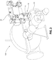
FIG. 2 is a perspective view of the steam turbine and pneumatic trip system; -
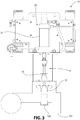
FIG. 3 is a rear view of the pneumatic trip system ofFIG. 2 in association with a flow path of the steam turbine; -
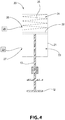
FIG. 4 is a schematic illustrating an actuator assembly of the pneumatic trip system ofFIG. 3 ; -
FIG. 5 is an electrical schematic of a pneumatic circuit of the actuator assembly ofFIG. 4 ; -
FIG. 6A is a pneumatic schematic of the actuator assembly ofFIG. 4 in a first operational state; -
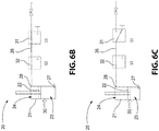
FIG. 6B is a pneumatic schematic of the actuator assembly ofFIG. 4 in a second operational state; and -
FIG. 6C is a pneumatic schematic of the actuator assembly ofFIG. 4 in a third operational state. - For purposes of the description hereinafter, the terms "end", "upper", "lower", "right", "left", "vertical", "horizontal", "top", "bottom", "lateral", "longitudinal", and derivatives thereof shall relate to the invention as it is oriented in the drawing figures. However, it is to be understood that the invention may assume various alternative variations and step sequences, except where expressly specified to the contrary. It is also to be understood that the specific devices and processes illustrated in the attached drawings, and described in the following specification, are simply exemplary embodiments or aspects of the invention. Hence, specific dimensions and other physical characteristics related to the embodiments or aspects disclosed herein are not to be considered as limiting.
- With reference to
FIGS. 1-6C , apneumatic trip system 10 for partially actuating a steamchest trip valve 11 of asteam turbine 100 is shown in accordance with a preferred and non-limiting embodiment or aspect of the present disclosure. Thepneumatic trip system 10 includes thetrip valve 11, which is made up of avalve member 12 operatively associated with aflow path 101 forming part of thesteam turbine 100 and avalve stem 13 connected to thevalve member 12. As shown inFIG. 3 , thevalve member 12 is actuated to be movable within theturbine flow path 101 to engage avalve seat 102 in theflow path 101 to close theflow path 101 and prevent fluid flow through theflow path 101. The valve stem 13 moves thevalve member 12 between an open position allowing fluid flow through theturbine flow path 101 and a closed position, in which thevalve member 12 engages thevalve seat 102, preventing fluid flow through theflow path 101. - With reference to
FIGS. 1-6C , thepneumatic trip system 10 also includes anactuator assembly 20 operatively connected to thevalve stem 13 of thetrip valve 11. As shown inFIGS. 4-6C , theactuator assembly 20 includes acylinder 21 and apiston 22 operatively connected to thevalve stem 13. Thepiston 22 is movably disposed within thecylinder 21 and divides thecylinder 21 into afirst chamber 23 defined below thepiston 22 and asecond chamber 24 defined above thepiston 22. Thepiston 22 is movable within thecylinder 21 between a first position corresponding to the open position of thetrip valve 11 and a second position corresponding to the closed position of thetrip valve 11. The valve stem 13 may extend into thecylinder 21 to engage the bottom of thepiston 22. Theactuator assembly 20 also includes a biasingelement 25 disposed in thesecond chamber 24 of thecylinder 21. The biasingelement 25 engages thepiston 22 to bias thepiston 22 toward the second position and thereby bias thevalve stem 13 and thevalve member 12 toward the closed position. Theactuator assembly 20 further includes apneumatic circuit 26 in communication with thesecond chamber 24. As shown inFIG. 4 , the biasingelement 25 is a compression spring. However it is to be appreciated that the biasing element may be of any type of structure or configuration suitable for being incorporated within theactuator assembly 20 and sufficiently resilient to force thevalve member 12 into the closed position when thetrip valve 11 is actuated. - As shown in
FIGS. 4 and 6A-6C , thecylinder 21 includes afirst port 27 defined in a lower portion of thecylinder 21 for placing thefirst chamber 23 in communication with an exterior of thecylinder 21 such that thefirst chamber 23 can be pressurized to cause thepiston 22 to remain in the first position and thereby hold thevalve stem 13 and thevalve member 12 in the open position. Thecylinder 21 also includes asecond port 28 defined in an upper portion of thecylinder 21 for placing thesecond chamber 24 in communication with thepneumatic circuit 26. Thepneumatic circuit 26 pressurizes thesecond chamber 24 to, in combination with the biasingelement 25, actuate thepiston 22 to move to an intermediate position, shown inFIG. 3 , between the first position and the second position corresponding to an exercised position of thetrip valve 11 while thefirst chamber 23 is pressurized. Thepiston 22 thereby moves thevalve stem 13 and thevalve member 12 to an exercised position between the open position and the closed position while thefirst chamber 23 is pressurized. Thevalve member 12 allows fluid flow through theturbine flow path 101 in the exercised position. - As shown in
FIG. 4 , thepneumatic trip system 10 also includes apneumatic mechanism 29 that pressurizes thefirst chamber 23 of thecylinder 21 to cause thepiston 22 to hold thevalve stem 13 and thevalve member 12 in the open position and to release pressure from thefirst chamber 23 to allow thepiston 22 to move thevalve stem 13 and thevalve member 12 to the closed position under the bias of the biasingelement 25. According to the invention, thepneumatic mechanism 29 is a Pneumatic Overspeed Trip System known to those having ordinary skill in the art and commonly used to trip thevalve 11 to close theflow path 101 during an emergency shutdown of thesteam turbine 100. It is to be appreciated that thepneumatic mechanism 29 may be of any type or configuration found to be suitable for holding thetrip valve 11 in the open position, as discussed above. Accordingly, thepneumatic circuit 26 causes actuation of thetrip valve 11 through a partial stroke without requiring a complete closure of thevalve 11, thereby allowing continued operation of thesteam turbine 100 with the safety mechanism of the Pneumatic Overspeed Trip System (pneumatic mechanism 29) in place and capable of actuating thetrip valve 11 to close theflow path 101. - As shown in
FIGS. 5 , thepneumatic circuit 26 includes anactivation switch 33 operatively connected or coupled to amanual rotary switch 34. Theactivation switch 33 activates thepneumatic circuit 26 to pressurize thesecond chamber 24 of thecylinder 21 and initiate a partial trip of thevalve 11 to exercise thevalve 11. Theactivation switch 33 also deactivates thepneumatic circuit 26 to release pressure from thesecond chamber 24 after thetrip valve 11 has been exercised to allow thevalve stem 13 and thevalve member 12 to return to the open position under the pressure applied to thefirst chamber 23 of thecylinder 21. - With reference to
FIGS. 5-6C , after thepneumatic circuit 26 is activated by theactivation switch 33, thepneumatic circuit 26 is configured to stop pressurizing thesecond chamber 24 of thecylinder 21 when thepiston 22 reaches the intermediate position and thevalve stem 13 and thevalve member 12 thereby reach the exercised position. Thepneumatic circuit 26 will also retain pressure in thesecond chamber 24 to hold thepiston 22 in the intermediate position and thevalve stem 13 and thevalve member 12 in the exercised position. In particular,pneumatic circuit 26 further includes afirst solenoid 31 and asecond solenoid 32. Thefirst solenoid 31 is coupled to alimit switch 30 that is actuated by thepiston 22 when the piston moves to the intermediate position and thereby moves thevalve stem 13 and thevalve member 12 to the exercised position. - As shown in
FIG. 6A , in an initial operational state, thepneumatic circuit 26 is deactivated and both the first andsecond solenoids second chamber 24 of thecylinder 21. As shown inFIG. 6B , when thepneumatic circuit 26 is activated by actuation of theactivation switch 33 via actuation of therotary switch 34, a partial stroke of thetrip valve 11 is initiated by actuating thefirst solenoid 31 and thesecond solenoid 32 to slowly pressurize thesecond chamber 24 of thecylinder 21. As thesecond chamber 24 is pressurized, thepiston 22 is forced downwardly against the pressure in thefirst chamber 23 to movepiston 22 away from the first position and thereby move thevalve stem 13 and thevalve member 12 away from the open position. - As shown in
FIG. 6C , as thepiston 22 moves downwardly within thecylinder 21, thepiston 22 actuates thelimit switch 30 to open when thepiston 22 reaches the intermediate position and thevalve stem 13 and thevalve member 12 thereby reach the exercised position. This, in turn, actuates thefirst solenoid 31 and thesecond solenoid 32 to stop pressurizing thesecond chamber 24 and retain the pressure in thesecond chamber 24 to thereby hold thepiston 22 in the intermediate position and thevalve stem 13 and thevalve member 12 in the exercised position. According to one particular and non-limiting embodiment or aspect of the present disclosure, thepneumatic circuit 26 causes thepiston 22 and thereby thevalve stem 13 and thevalve member 12 to move a distance of approximately 0,009525 m (3/8") from the first/open position to the intermediate/exercised position, though it is to be appreciated that the distance between the open position and the exercised position of thetrip valve 11 may be set to any distance found to be suitable to those having ordinary skill in the art so long as thevalve member 12 remains sufficiently distant from thevalve seat 102 in theturbine flow path 101 to allow for free flow of fluid through theflow path 101. According to another particular and non-limiting embodiment or aspect of the present disclosure, the position of thelimit switch 30 on thecylinder 21 is adjustable to thereby adjust the intermediate/exercised position. - When the
rotary switch 34 is released by the operator, theactivation switch 33 is opened and thepneumatic circuit 26 is deactivated. When thepneumatic circuit 26 is deactivated, thefirst solenoid 31 and thesecond solenoid 32 are actuated to release the pressure from thesecond chamber 24 of thecylinder 21 thereby allowing thevalve stem 13 and thevalve member 12 to return to the open position and theactuator assembly 20 to return to the normal operational state depicted inFIG. 6A . According to one particular embodiment or aspect of the present disclosure, the first andsecond solenoids second chamber 24 of thecylinder 21 open to atmosphere when thepneumatic circuit 26 is deactivated. - With reference to
FIGS. 1-6C , a method of exercising atrip valve 11 of apneumatic trip system 10 for asteam turbine 100 is provided in accordance with a preferred and non-limiting embodiment or aspect of the invention. Thetrip valve 11 includes avalve member 12 operatively associated with aturbine flow path 101 and avalve stem 13 connected to thevalve member 12. Thevalve member 12 is configured to be actuated to engage theturbine flow path 101 to close theflow path 101 and prevent fluid flow through theturbine flow path 101. The method includes providing anactuator assembly 20 operatively connected to thevalve stem 13. Theactuator assembly 20 includes acylinder 21; apiston 22 movably disposed within thecylinder 21 and dividing thecylinder 21 into afirst chamber 23 and asecond chamber 24; a biasingelement 25 disposed in thesecond chamber 24 of thecylinder 21, the biasingelement 25 engaging thepiston 22; and apneumatic circuit 26 in communication with thesecond chamber 24 of thecylinder 21. Thepiston 22 is operatively connected to thevalve stem 13 to move thevalve stem 13 and thevalve member 12 between an open position allowing fluid flow through theturbine flow path 101 and closed position preventing fluid flow through theturbine flow path 101. The biasingelement 25 engages thepiston 22 to bias thevalve stem 13 and thevalve member 12 toward the closed position. Thecylinder 21 includes afirst port 27 for placing thefirst chamber 23 in communication with an exterior of thecylinder 21 such that thefirst chamber 23 of thecylinder 21 can be pressurized to cause thepiston 22 to hold thevalve stem 13 and thevalve member 12 in the open position. Thecylinder 21 includes asecond port 28 for placing thesecond chamber 24 in communication with thepneumatic circuit 26. The method further includes activating thepneumatic circuit 26 to pressurize thesecond chamber 24 of thecylinder 21 to actuate thepiston 22 to move thevalve stem 13 and thevalve member 12 to an exercised position between the open position and the closed position while thefirst chamber 23 is pressurized; activating thepneumatic circuit 26 to stop pressurizing thesecond chamber 24 when thevalve stem 13 and thevalve member 12 reach the exercised position and retain pressure in thesecond chamber 24 to hold thevalve stem 13 and thevalve member 12 in the exercised position; and deactivatingpneumatic circuit 26 to release the pressure from thesecond chamber 24 and allow thevalve stem 13 and thevalve member 12 to return to the open position. Thevalve member 12 allows fluid flow through theturbine flow path 101 in the exercised position. - The method may also include pressurizing the
first chamber 23 of thecylinder 21 to cause thepiston 22 to hold thevalve stem 13 and thevalve member 12 in the open position; and releasing the pressure from thefirst chamber 23 of thecylinder 21 to allow thepiston 22 to move thevalve stem 13 and thevalve member 12 to the closed position under the bias of the biasingelement 25. - It is to be understood that the invention may assume various alternative variations and step sequences, except where expressly specified to the contrary. It is also to be understood that the specific devices and processes illustrated in the attached drawings, and described in the specification, are simply exemplary embodiments or aspects of the invention. Although the invention has been described in detail for the purpose of illustration based on what is currently considered to be the most practical and preferred embodiments or aspects, it is to be understood that such detail is solely for that purpose and that the invention is not limited to the disclosed embodiments or aspects, but, on the contrary, is limited to the appended claims. For example, it is to be understood that the present invention contemplates that, to the extent possible, one or more features of any embodiment or aspect can be combined with one or more features of any other embodiment or aspect.
Claims (15)
- An actuator assembly (20) for a pneumatic trip system (10), the actuator assembly (20) comprising:a cylinder (21);a piston (22) configured to be connected to a trip valve (11), the piston (22) being movably disposed within the cylinder (21) between a first position corresponding to an open position of the trip valve (11) and a second position corresponding to a closed position of the trip valve (11), and the piston (22) dividing the cylinder (21) into a first chamber (23) and a second chamber (24);a biasing element (25) disposed in the second chamber (24) of the cylinder (21), the biasing element (25) engaging the piston (22) to bias piston (22) toward the second position;wherein the cylinder (21) includes a first port (27) for placing the first chamber (23) in communication with an exterior of the cylinder (21) such that the first chamber (23) of the cylinder (21) can be pressurized to cause the piston (22) to remain in the first position, and wherein the actuator assembly (20) further comprises a pneumatic mechanism (29) in communication with the first chamber (23) of the cylinder (21) via the first port (27) and configured to pressurize the first chamber (23) of the cylinder (21) to hold the piston (22) in the first position and to release pressure from the first chamber (23) of the cylinder (21) to allow the piston (22) to move to the second position under the bias of the biasing element (25), characterized in that the actuator assembly comprises a pneumatic circuit (26) in communication with the second chamber (24) of the cylinder (21), wherein the cylinder (21) includes a second port (28) for placing the second chamber (24) in communication with the pneumatic circuit (26),wherein the pneumatic circuit (26) is configured to pressurize the second chamber (24) of the cylinder (21) to actuate the piston (22) to move to an intermediate position between the first position and the second position corresponding to an exercised position of the trip valve (11) while the first chamber (23) is pressurized by the pneumatic mechanism (29), andwherein the pneumatic mechanism (29) is a Pneumatic Overspeed Trip System and the Pneumatic Overspeed Trip System is configured to be operated to allow the piston (22) to move to the second position independent of the pneumatic circuit (26).
- The actuator assembly (20) according to claim 1, wherein the pneumatic circuit (26) is configured to stop pressurizing the second chamber (24) when the piston (22) reaches the intermediate position and retain pressure in the second chamber (24) to hold the piston (22) in the intermediate position.
- The actuator assembly (20) according to claim 2, wherein the pneumatic circuit (26) comprises a limit switch (30) actuated by the piston (22) when the piston (22) reaches the intermediate position, and wherein the limit switch (30) is configured to cause the pneumatic circuit (26) to stop pressurizing the second chamber (24) and to retain the pressure in the second chamber (24) when actuated by the piston (22).
- The actuator assembly (20) according to claim 2, wherein the pneumatic circuit (26) comprises a first solenoid (31) and a second solenoid (32), wherein the first solenoid (31) and the second solenoid (32) are actuated to pressurize the second chamber of the cylinder (21) when the pneumatic circuit (26) is activated, wherein the first solenoid (31) and the second solenoid (32) are actuated to stop pressurizing the second chamber (24) and to retain the pressure in the second chamber (24) when the piston (22) reaches the intermediate position, and wherein the first solenoid (31) and the second solenoid (32) are actuated to release the pressure from the second chamber (24) when the pneumatic circuit (26) is deactivated.
- The actuator assembly (20) according to claim 1, wherein the pneumatic circuit (26) comprises an activation switch (33) configured to activate the pneumatic circuit (26) to pressurize the second chamber (24) of the cylinder (21) and to deactivate the pneumatic circuit (26) to release pressure from the second chamber (24).
- The actuator assembly (20) according to claim 5, wherein the activation switch (33) is operatively connected to a rotary switch (34).
- The actuator assembly (20) according to claim 1, wherein the biasing element (25) comprises a compression spring.
- A pneumatic trip system (10) for a turbine (100), comprising:a valve member (12) operatively associated with a turbine flow path (101), the valve member (12) being configured to be actuated to engage the turbine flow path (101) to close the flow path (101) and prevent fluid flow through the turbine flow path (101);a valve stem (13) connected to the valve member (12), the valve stem (13) being configured to move the valve member (12) between an open position allowing fluid flow through the turbine flow path (101) and a closed position preventing fluid flow through the turbine flow path (101); andan actuator assembly (20), operatively connected to the valve stem (13), the actuator assembly comprising:a cylinder (21);a piston (22) operatively connected to the valve stem (13), the piston (22) being movably disposed within the cylinder (21) and dividing the cylinder (21) into a first chamber (23) and a second chamber (24);a biasing element (25) disposed in the second chamber (24) of the cylinder, the biasing element (25) engaging the piston (22) to bias the valve stem (13) and the valve member (12) toward the closed position;wherein the cylinder includes a first port (27) for placing the first chamber (23) in communication with an exterior of the cylinder (21) such that the first chamber (23) of the cylinder (21) can be pressurized to cause the piston (22) to hold the valve stem (13) and the valve member (12) in the open position, and wherein the actuator assembly further comprises a pneumatic mechanism (29) in communication with the first chamber (23) of the cylinder (21) via the first port (27) and configured to pressurize the first chamber (23) of the cylinder (21) to cause the piston (22) to hold the valve stem (13) and the valve member (12) in the open position and to release pressure from the first chamber (23) of the cylinder (21) to allow the piston (22) to move the valve stem (13) and the valve member (12) to the closed position under the bias of the biasing element (25), characterized in that the actuator assembly comprises a pneumatic circuit (26) in communication with the second chamber (24) of the cylinder (21), wherein the cylinder (21) includes a second port (28) for placing the second chamber (24) in communication with the pneumatic circuit (26),wherein the pneumatic circuit (26) is configured to pressurize the second chamber (24) of the cylinder (21) to actuate the piston (22) to move the valve stem (13) and the valve member (12) to an exercised position between the open position and the closed position while the first chamber (23) is pressurized by the pneumatic mechanism (29), the valve member (12) allowing fluid flow through the turbine flow path (101) in the exercised position, andwherein the pneumatic mechanism (29) is a Pneumatic Overspeed Trip System and the Pneumatic Overspeed Trip System is configured to be operated to allow the valve member (12) to move to the closed position independent of the pneumatic circuit (26).
- The pneumatic trip system (10) according to claim 8, wherein the pneumatic circuit (26) is configured to stop pressurizing the second chamber (24) when the valve stem (13) and the valve member (12) reach the exercised position and retain pressure in the second chamber (24) to hold the valve stem (13) and the valve member (12) in the exercised position.
- The pneumatic trip system (10) according to claim 9, wherein the pneumatic circuit (26) comprises a limit switch (30) actuated by the piston (22) when the piston (22) moves the valve stem (13) and the valve member (12) to the exercised position, and wherein the limit switch (30) is configured to cause the pneumatic circuit (26) to stop pressurizing the second chamber (24) and to retain the pressure in the second chamber (24) when actuated by the piston (22).
- The pneumatic trip system (10) according to claim 9, wherein the pneumatic circuit (26) comprises a first solenoid (31) and a second solenoid (32), wherein the first solenoid (31) and the second solenoid (32) are actuated to pressurize the second chamber (24) of the cylinder when the pneumatic circuit (26) is activated, wherein the first solenoid (31) and the second solenoid (32) are actuated to stop pressurizing the second chamber (24) and retain the pressure in the second chamber (24) when the valve stem (13) and the valve member (12) are in the exercised position, and wherein the first solenoid (31) and the second solenoid (32) are actuated to release the pressure from the second chamber (24) when the pneumatic circuit (26) is deactivated.
- A method for exercising a trip valve (11) of a pneumatic trip system (10) for a turbine (100), wherein the trip valve (11) comprises a valve member (12) operatively associated with a turbine flow path (101) and a valve stem (13) connected to the valve member (12), and wherein the valve member (12) is configured to be actuated to engage the turbine flow path (101) to close the flow path (101) and prevent fluid flow through the turbine flow path (101), the method comprising:
providing an actuator assembly (20), operatively connected to the valve stem (13), the actuator assembly (20) comprising:a cylinder (21);a piston (22) movably disposed within the cylinder (21) and dividing the cylinder (21) into a first chamber (23) and a second chamber (24);a biasing element (25) disposed in the second chamber (24) of the cylinder (21), the biasing element (25) engaging the piston (22);a pneumatic circuit (26) in communication with the second chamber (24) of the cylinder (21),wherein the piston (22) is operatively connected to the valve stem (13) to move the valve stem (13) and the valve member (12) between an open position allowing fluid flow through the turbine flow path (101) and a closed position preventing fluid flow through the turbine flow path (101),wherein the biasing element (25) engages the piston (22) to bias the valve stem (13) and the valve member (12) toward the closed position,wherein the cylinder (21) includes a first port (27) for placing the first chamber (23) in communication with an exterior of the cylinder (21) such that the first chamber (23) of the cylinder (21) can be pressurized to cause the piston (22) to hold the valve stem (13) and the valve member (12) in the open position, andwherein the actuator assembly further comprises a pneumatic mechanism (29) in communication with the first chamber (23) of the cylinder (21) via the first port (27),wherein the cylinder (21) includes a second port (28) for placing the second chamber (24) in communication with the pneumatic circuit (26);pressurizing the first chamber (23) of the cylinder (21) with the pneumatic mechanism (29) to cause the piston (22) to hold the valve stem (13) and the valve member (12) in the open position;releasing the pressure from the first chamber (23) of the cylinder (21) with the pneumatic mechanism (29) to allow the piston (22) to move the valve stem (13) and the valve member (12) to the closed position under the bias of the biasing element (25);activating the pneumatic circuit (26) to pressurize the second chamber (24) of the cylinder (21) to actuate the piston (22) to move the valve stem (13) and the valve member (12) to an exercised position between the open position and the closed position while the first chamber (23) is pressurized by the pneumatic mechanism (29);activating the pneumatic circuit (26) to stop pressurizing the second chamber (24) when the valve stem (13) and the valve member (12) reach the exercised position and retain pressure in the second chamber (24) to hold the valve stem (13) and the valve member (12) in the exercised position; anddeactivating the pneumatic circuit (26) to release the pressure from the second chamber (24) and allow the valve stem (13) and the valve member (12) to return to the open position,wherein the valve member (12) allows fluid flow through the turbine flow path (101) in the exercised position, andwherein the pneumatic mechanism (29) is a Pneumatic Overspeed Trip System and the Pneumatic Overspeed Trip System is configured to be operated to allow the valve member (12) to move to the closed position independent of the pneumatic circuit (26). - The method according to claim 12, wherein the pneumatic circuit (26) comprises a limit switch (30) actuated by the piston (22) when the piston (22) moves the valve stem (13) and the valve member (12) to the exercised position, and wherein the limit switch (30) is configured to activate the pneumatic circuit (26) to stop pressurizing the second chamber (24) and to retain the pressure in the second chamber (24) when actuated by the piston (22).
- The method according to claim 12, wherein the pneumatic circuit (26) comprises a first solenoid (31) and a second solenoid (32), wherein the first solenoid (31) and the second solenoid (32) are actuated to pressurize the second chamber (24) of the cylinder (21) when the pneumatic circuit (26) is activated, wherein the first solenoid (31) and the second solenoid (32) are actuated to stop pressurizing the second chamber (24) and retain the pressure in the second chamber (24) when the valve stem (13) and the valve member (12) are in the exercised position, and wherein the first solenoid (31) and the second solenoid (32) are actuated to release the pressure from the second chamber (24) when the pneumatic circuit (26) is deactivated.
- The method according to claim 12, wherein the pneumatic circuit (26) comprises an activation switch (33) configured to activate the pneumatic circuit (26) to pressurize the second chamber (24) of the cylinder (21) and to deactivate the pneumatic circuit (26) to release the pressure from the second chamber (24).
Priority Applications (1)
| Application Number | Priority Date | Filing Date | Title |
|---|---|---|---|
| PL16852371T PL3247886T3 (en) | 2015-10-02 | 2016-09-26 | Pneumatic trip valve partial stroking arrangement |
Applications Claiming Priority (3)
| Application Number | Priority Date | Filing Date | Title |
|---|---|---|---|
| US201562236481P | 2015-10-02 | 2015-10-02 | |
| US15/272,871 US10648357B2 (en) | 2015-10-02 | 2016-09-22 | Pneumatic trip valve partial stroking arrangement |
| PCT/US2016/053766 WO2017058726A1 (en) | 2015-10-02 | 2016-09-26 | Pneumatic trip valve partial stroking arrangement |
Publications (3)
| Publication Number | Publication Date |
|---|---|
| EP3247886A1 EP3247886A1 (en) | 2017-11-29 |
| EP3247886A4 EP3247886A4 (en) | 2018-03-07 |
| EP3247886B1 true EP3247886B1 (en) | 2020-09-23 |
Family
ID=58424268
Family Applications (1)
| Application Number | Title | Priority Date | Filing Date |
|---|---|---|---|
| EP16852371.0A Active EP3247886B1 (en) | 2015-10-02 | 2016-09-26 | Pneumatic trip valve partial stroking arrangement |
Country Status (12)
| Country | Link |
|---|---|
| US (1) | US10648357B2 (en) |
| EP (1) | EP3247886B1 (en) |
| JP (1) | JP6911273B2 (en) |
| KR (1) | KR102575421B1 (en) |
| CN (1) | CN107407159B (en) |
| BR (1) | BR112017018642B1 (en) |
| CA (1) | CA2972508A1 (en) |
| MX (1) | MX392013B (en) |
| PL (1) | PL3247886T3 (en) |
| RU (1) | RU2722289C2 (en) |
| TW (1) | TWI722020B (en) |
| WO (1) | WO2017058726A1 (en) |
Families Citing this family (6)
| Publication number | Priority date | Publication date | Assignee | Title |
|---|---|---|---|---|
| DE102015221311A1 (en) * | 2015-10-30 | 2017-05-04 | Siemens Aktiengesellschaft | Turbine with quick-closing and control valves |
| CN119123121A (en) * | 2019-08-22 | 2024-12-13 | 易斯拓克自动化有限公司 | Pneumatic shut-off valve |
| RU2762812C1 (en) * | 2020-12-18 | 2021-12-23 | Общество с ограниченной ответственностью "Камоцци Пневматика" | Pneumatic direct flow valve with position sensor |
| CN112762039B (en) * | 2021-01-08 | 2023-02-03 | 中国铁建重工集团股份有限公司 | Full-pneumatic automatic control system for vacuum slag discharge pump |
| CN115854103B (en) * | 2022-11-17 | 2026-02-06 | 湖南卓誉科技有限公司 | Double-cylinder two-position five-way valve |
| KR102764487B1 (en) * | 2024-07-16 | 2025-02-07 | 송필섭 | Air supply apparatus for valve driving |
Citations (2)
| Publication number | Priority date | Publication date | Assignee | Title |
|---|---|---|---|---|
| US20090222233A1 (en) * | 2008-02-28 | 2009-09-03 | Tareg Nasser Al-Buaijan | Partial stroke testing system coupled with fuel control valve |
| US20110315904A1 (en) * | 2010-06-23 | 2011-12-29 | Thomas Karte | Pneumatic actuator and method for operating the pneumatic actuator |
Family Cites Families (33)
| Publication number | Priority date | Publication date | Assignee | Title |
|---|---|---|---|---|
| US3682564A (en) | 1971-04-26 | 1972-08-08 | Laval Turbine | Turbine overspeed trip system with testing mechanism |
| JPS5126348Y2 (en) * | 1971-09-03 | 1976-07-05 | ||
| US3987818A (en) | 1975-06-19 | 1976-10-26 | Turbodyne Corporation | Safety trip valve for steam or gas turbines with means to assure controlled opening from the closed position |
| US4040600A (en) | 1976-01-15 | 1977-08-09 | General Electric Company | Shut-off valve |
| JPS5594686A (en) | 1979-01-16 | 1980-07-18 | Mitsubishi Heavy Ind Ltd | Submerged filter bed tower |
| US4335744A (en) | 1980-04-07 | 1982-06-22 | Control Components, Inc. | Quiet safety relief valve |
| DE3019602C2 (en) | 1980-05-22 | 1984-10-11 | Kraftwerk Union AG, 4330 Mülheim | Electro-hydraulic actuator for turbine valves |
| US4379544A (en) | 1981-05-01 | 1983-04-12 | Elliott Turbomachinery Company, Inc. | Turbine trip valve mechanism |
| US4679769A (en) | 1984-07-27 | 1987-07-14 | Westinghouse Electric Corp. | Steam turbine control valve for cyclic duty |
| US4840057A (en) | 1988-02-19 | 1989-06-20 | Bingham George H | Method and apparatus for testing relief valve |
| JP2960584B2 (en) * | 1991-09-12 | 1999-10-06 | 株式会社日立製作所 | Hydraulic control unit for combined cycle power plant |
| CN2167192Y (en) | 1993-03-11 | 1994-06-01 | 樊县圃 | Pneumatic executive mechanism for speed adjustment for steam turbine |
| JP3341511B2 (en) * | 1995-01-13 | 2002-11-05 | 富士電機株式会社 | Stem-free test equipment for main steam stop valve |
| US6082393A (en) | 1997-10-22 | 2000-07-04 | Tye; Randy G. | Emergency shutoff valve exerciser for steam turbine and methods for installing and operating same |
| JP2001096371A (en) | 1999-07-23 | 2001-04-10 | Dengensha Mfg Co Ltd | Electrode opening stroke control method and device |
| US6435022B1 (en) | 2001-02-09 | 2002-08-20 | Tareq Nasser Albuaijan | Partial stroke testing system |
| US6631882B2 (en) | 2001-08-09 | 2003-10-14 | Robert Mack | Method and apparatus to test a shutdown device while process continues to operate |
| JP3680012B2 (en) | 2001-08-14 | 2005-08-10 | 三菱重工業株式会社 | Steam valve drive controller |
| US6935610B1 (en) | 2003-01-17 | 2005-08-30 | Dynatorque, Inc. | Partial stroke valve test apparatus |
| US7234678B1 (en) | 2003-09-22 | 2007-06-26 | Kabushiki Kaisha Toshiba | Protection system for turbo machine and power generating equipment |
| DE102005004477B4 (en) | 2005-01-31 | 2013-02-07 | Samson Ag | Method for checking the operability of an actuator, in particular for a safety valve |
| JP4544529B2 (en) * | 2005-07-29 | 2010-09-15 | セイコーインスツル株式会社 | Vacuum chuck |
| JP4943126B2 (en) | 2006-11-30 | 2012-05-30 | 株式会社キッツ | Emergency shut-off actuator with test moving mechanism |
| US7536984B2 (en) | 2007-04-16 | 2009-05-26 | Lgd Technology, Llc | Variable valve actuator with a pneumatic booster |
| DE102008024253A1 (en) | 2008-05-20 | 2009-11-26 | Man Turbo Ag | Control device and method for a quick-closing valve of a steam turbine |
| US8413499B2 (en) | 2008-09-22 | 2013-04-09 | Honeywell International Inc. | Partial stroke testing |
| DE102009011132A1 (en) * | 2009-03-03 | 2010-09-30 | Judo Wasseraufbereitung Gmbh | Method for operating a water softening system with setpoint control by a water removal station |
| US8192172B2 (en) * | 2009-04-06 | 2012-06-05 | Woodward, Inc. | Flow sensing shutoff valve |
| US8996328B2 (en) | 2009-12-29 | 2015-03-31 | Fisher Controls International Llc | Methods, apparatus and articles of manufacture to test safety instrumented system solenoids |
| DE102011104530A1 (en) | 2011-02-04 | 2012-08-09 | Robert Bosch Gmbh | Hydraulic actuating arrangement |
| US20120199211A1 (en) | 2011-02-08 | 2012-08-09 | Hamilton Sundstrand Corporation | Airflow control system |
| EP2620655A1 (en) | 2012-01-30 | 2013-07-31 | Siemens Aktiengesellschaft | Drive system for a valve |
| US9057450B2 (en) | 2013-03-13 | 2015-06-16 | Elliott Company | Valve exerciser for an emergency shutoff valve of a steam turbine and method for using the same |
-
2016
- 2016-09-22 US US15/272,871 patent/US10648357B2/en active Active
- 2016-09-26 MX MX2017011313A patent/MX392013B/en unknown
- 2016-09-26 JP JP2017535906A patent/JP6911273B2/en active Active
- 2016-09-26 CN CN201680012950.3A patent/CN107407159B/en active Active
- 2016-09-26 PL PL16852371T patent/PL3247886T3/en unknown
- 2016-09-26 BR BR112017018642-0A patent/BR112017018642B1/en active IP Right Grant
- 2016-09-26 CA CA2972508A patent/CA2972508A1/en not_active Abandoned
- 2016-09-26 EP EP16852371.0A patent/EP3247886B1/en active Active
- 2016-09-26 WO PCT/US2016/053766 patent/WO2017058726A1/en not_active Ceased
- 2016-09-26 RU RU2017124603A patent/RU2722289C2/en active
- 2016-09-26 KR KR1020177018715A patent/KR102575421B1/en active Active
- 2016-09-29 TW TW105131185A patent/TWI722020B/en active
Patent Citations (2)
| Publication number | Priority date | Publication date | Assignee | Title |
|---|---|---|---|---|
| US20090222233A1 (en) * | 2008-02-28 | 2009-09-03 | Tareg Nasser Al-Buaijan | Partial stroke testing system coupled with fuel control valve |
| US20110315904A1 (en) * | 2010-06-23 | 2011-12-29 | Thomas Karte | Pneumatic actuator and method for operating the pneumatic actuator |
Also Published As
| Publication number | Publication date |
|---|---|
| MX392013B (en) | 2025-03-21 |
| JP2018536788A (en) | 2018-12-13 |
| BR112017018642B1 (en) | 2022-11-16 |
| KR20180056586A (en) | 2018-05-29 |
| WO2017058726A1 (en) | 2017-04-06 |
| TWI722020B (en) | 2021-03-21 |
| EP3247886A1 (en) | 2017-11-29 |
| RU2017124603A (en) | 2019-01-11 |
| PL3247886T3 (en) | 2021-02-08 |
| BR112017018642A2 (en) | 2018-04-17 |
| EP3247886A4 (en) | 2018-03-07 |
| TW201722823A (en) | 2017-07-01 |
| KR102575421B1 (en) | 2023-09-07 |
| CA2972508A1 (en) | 2017-04-06 |
| JP6911273B2 (en) | 2021-07-28 |
| CN107407159B (en) | 2021-01-22 |
| CN107407159A (en) | 2017-11-28 |
| RU2017124603A3 (en) | 2019-11-18 |
| US20170096908A1 (en) | 2017-04-06 |
| US10648357B2 (en) | 2020-05-12 |
| RU2722289C2 (en) | 2020-05-28 |
| MX2017011313A (en) | 2017-12-07 |
Similar Documents
| Publication | Publication Date | Title |
|---|---|---|
| US10648357B2 (en) | Pneumatic trip valve partial stroking arrangement | |
| EP3220221B1 (en) | Testing of safety devices | |
| US11169552B2 (en) | Solenoid initiator with a manual override for inflation system | |
| EP3360773B1 (en) | Solenoid valve for inflation system | |
| EP2391842B1 (en) | Actuator having an override apparatus | |
| RU2505730C2 (en) | Control air valve | |
| US20100037966A1 (en) | Method for checking the functionality of an actuator | |
| WO2012014095A1 (en) | High pressure mechanical safety valve | |
| JP2012251638A (en) | Emergency shutoff valve device | |
| JP2018536788A5 (en) | ||
| CN108350750A (en) | Turbine with quick closing valve and regulating valve | |
| EP3628898B1 (en) | Three-position poppet valve | |
| ATE523699T1 (en) | HYDRAULIC/PNEUMATIC CONTROL VALVE WITH FAIL-SAFE FUNCTION | |
| EP3333376A1 (en) | Electric control circuit for a turbine engine | |
| EP2428686B1 (en) | System for controlling a hydraulic actuator for the rise and descent of a load | |
| KR20180045248A (en) | Emergency valve unit of valve assembly | |
| EP2166262B1 (en) | Pedal driving construction for pneumatic valves and the like | |
| JP5512611B2 (en) | Circuit breaker fluid pressure driving apparatus and driving method thereof | |
| WO2012038282A3 (en) | Pneumatic control valve assembly for regulating the brake cylinder pressure of an automatic indirect compressed-air brake | |
| EP1895169A1 (en) | A high pressure relief and control valve assembly | |
| WO2019048850A1 (en) | Partial stroke test for a pneumatic valve actuator | |
| DE4441780A1 (en) | Pressure operated positioner for activating door lock | |
| DE102011111043A1 (en) | Method for self-testing of pneumatic drive, involves receiving self-test control signal and detecting actual position of actuator by position controller, where position controller moves drive of predetermined test stroke | |
| CZ301587B6 (en) | Mechanical drive of quick-closing valve for turbine |
Legal Events
| Date | Code | Title | Description |
|---|---|---|---|
| STAA | Information on the status of an ep patent application or granted ep patent |
Free format text: STATUS: THE INTERNATIONAL PUBLICATION HAS BEEN MADE |
|
| PUAI | Public reference made under article 153(3) epc to a published international application that has entered the european phase |
Free format text: ORIGINAL CODE: 0009012 |
|
| STAA | Information on the status of an ep patent application or granted ep patent |
Free format text: STATUS: REQUEST FOR EXAMINATION WAS MADE |
|
| 17P | Request for examination filed |
Effective date: 20170803 |
|
| AK | Designated contracting states |
Kind code of ref document: A1 Designated state(s): AL AT BE BG CH CY CZ DE DK EE ES FI FR GB GR HR HU IE IS IT LI LT LU LV MC MK MT NL NO PL PT RO RS SE SI SK SM TR |
|
| AX | Request for extension of the european patent |
Extension state: BA ME |
|
| A4 | Supplementary search report drawn up and despatched |
Effective date: 20180205 |
|
| RIC1 | Information provided on ipc code assigned before grant |
Ipc: F16K 37/00 20060101ALI20180130BHEP Ipc: F01D 19/00 20060101ALI20180130BHEP Ipc: F01D 21/00 20060101ALI20180130BHEP Ipc: F01D 17/10 20060101ALI20180130BHEP Ipc: F01D 21/02 20060101ALI20180130BHEP Ipc: F01D 21/16 20060101AFI20180130BHEP Ipc: F15B 19/00 20060101ALI20180130BHEP |
|
| DAV | Request for validation of the european patent (deleted) | ||
| STAA | Information on the status of an ep patent application or granted ep patent |
Free format text: STATUS: EXAMINATION IS IN PROGRESS |
|
| 17Q | First examination report despatched |
Effective date: 20190129 |
|
| GRAP | Despatch of communication of intention to grant a patent |
Free format text: ORIGINAL CODE: EPIDOSNIGR1 |
|
| STAA | Information on the status of an ep patent application or granted ep patent |
Free format text: STATUS: GRANT OF PATENT IS INTENDED |
|
| INTG | Intention to grant announced |
Effective date: 20200508 |
|
| GRAS | Grant fee paid |
Free format text: ORIGINAL CODE: EPIDOSNIGR3 |
|
| GRAA | (expected) grant |
Free format text: ORIGINAL CODE: 0009210 |
|
| STAA | Information on the status of an ep patent application or granted ep patent |
Free format text: STATUS: THE PATENT HAS BEEN GRANTED |
|
| AK | Designated contracting states |
Kind code of ref document: B1 Designated state(s): AL AT BE BG CH CY CZ DE DK EE ES FI FR GB GR HR HU IE IS IT LI LT LU LV MC MK MT NL NO PL PT RO RS SE SI SK SM TR |
|
| AX | Request for extension of the european patent |
Extension state: BA ME |
|
| REG | Reference to a national code |
Ref country code: GB Ref legal event code: FG4D |
|
| REG | Reference to a national code |
Ref country code: CH Ref legal event code: EP |
|
| REG | Reference to a national code |
Ref country code: IE Ref legal event code: FG4D |
|
| REG | Reference to a national code |
Ref country code: DE Ref legal event code: R096 Ref document number: 602016044712 Country of ref document: DE Ref country code: AT Ref legal event code: REF Ref document number: 1316570 Country of ref document: AT Kind code of ref document: T Effective date: 20201015 |
|
| PG25 | Lapsed in a contracting state [announced via postgrant information from national office to epo] |
Ref country code: HR Free format text: LAPSE BECAUSE OF FAILURE TO SUBMIT A TRANSLATION OF THE DESCRIPTION OR TO PAY THE FEE WITHIN THE PRESCRIBED TIME-LIMIT Effective date: 20200923 Ref country code: SE Free format text: LAPSE BECAUSE OF FAILURE TO SUBMIT A TRANSLATION OF THE DESCRIPTION OR TO PAY THE FEE WITHIN THE PRESCRIBED TIME-LIMIT Effective date: 20200923 Ref country code: NO Free format text: LAPSE BECAUSE OF FAILURE TO SUBMIT A TRANSLATION OF THE DESCRIPTION OR TO PAY THE FEE WITHIN THE PRESCRIBED TIME-LIMIT Effective date: 20201223 Ref country code: GR Free format text: LAPSE BECAUSE OF FAILURE TO SUBMIT A TRANSLATION OF THE DESCRIPTION OR TO PAY THE FEE WITHIN THE PRESCRIBED TIME-LIMIT Effective date: 20201224 Ref country code: FI Free format text: LAPSE BECAUSE OF FAILURE TO SUBMIT A TRANSLATION OF THE DESCRIPTION OR TO PAY THE FEE WITHIN THE PRESCRIBED TIME-LIMIT Effective date: 20200923 Ref country code: BG Free format text: LAPSE BECAUSE OF FAILURE TO SUBMIT A TRANSLATION OF THE DESCRIPTION OR TO PAY THE FEE WITHIN THE PRESCRIBED TIME-LIMIT Effective date: 20201223 |
|
| REG | Reference to a national code |
Ref country code: AT Ref legal event code: MK05 Ref document number: 1316570 Country of ref document: AT Kind code of ref document: T Effective date: 20200923 |
|
| PG25 | Lapsed in a contracting state [announced via postgrant information from national office to epo] |
Ref country code: RS Free format text: LAPSE BECAUSE OF FAILURE TO SUBMIT A TRANSLATION OF THE DESCRIPTION OR TO PAY THE FEE WITHIN THE PRESCRIBED TIME-LIMIT Effective date: 20200923 Ref country code: LV Free format text: LAPSE BECAUSE OF FAILURE TO SUBMIT A TRANSLATION OF THE DESCRIPTION OR TO PAY THE FEE WITHIN THE PRESCRIBED TIME-LIMIT Effective date: 20200923 |
|
| REG | Reference to a national code |
Ref country code: NL Ref legal event code: MP Effective date: 20200923 |
|
| REG | Reference to a national code |
Ref country code: LT Ref legal event code: MG4D |
|
| PG25 | Lapsed in a contracting state [announced via postgrant information from national office to epo] |
Ref country code: RO Free format text: LAPSE BECAUSE OF FAILURE TO SUBMIT A TRANSLATION OF THE DESCRIPTION OR TO PAY THE FEE WITHIN THE PRESCRIBED TIME-LIMIT Effective date: 20200923 Ref country code: PT Free format text: LAPSE BECAUSE OF FAILURE TO SUBMIT A TRANSLATION OF THE DESCRIPTION OR TO PAY THE FEE WITHIN THE PRESCRIBED TIME-LIMIT Effective date: 20210125 Ref country code: LT Free format text: LAPSE BECAUSE OF FAILURE TO SUBMIT A TRANSLATION OF THE DESCRIPTION OR TO PAY THE FEE WITHIN THE PRESCRIBED TIME-LIMIT Effective date: 20200923 Ref country code: EE Free format text: LAPSE BECAUSE OF FAILURE TO SUBMIT A TRANSLATION OF THE DESCRIPTION OR TO PAY THE FEE WITHIN THE PRESCRIBED TIME-LIMIT Effective date: 20200923 Ref country code: SM Free format text: LAPSE BECAUSE OF FAILURE TO SUBMIT A TRANSLATION OF THE DESCRIPTION OR TO PAY THE FEE WITHIN THE PRESCRIBED TIME-LIMIT Effective date: 20200923 |
|
| REG | Reference to a national code |
Ref country code: CH Ref legal event code: PL |
|
| PG25 | Lapsed in a contracting state [announced via postgrant information from national office to epo] |
Ref country code: AT Free format text: LAPSE BECAUSE OF FAILURE TO SUBMIT A TRANSLATION OF THE DESCRIPTION OR TO PAY THE FEE WITHIN THE PRESCRIBED TIME-LIMIT Effective date: 20200923 Ref country code: AL Free format text: LAPSE BECAUSE OF FAILURE TO SUBMIT A TRANSLATION OF THE DESCRIPTION OR TO PAY THE FEE WITHIN THE PRESCRIBED TIME-LIMIT Effective date: 20200923 Ref country code: ES Free format text: LAPSE BECAUSE OF FAILURE TO SUBMIT A TRANSLATION OF THE DESCRIPTION OR TO PAY THE FEE WITHIN THE PRESCRIBED TIME-LIMIT Effective date: 20200923 Ref country code: IS Free format text: LAPSE BECAUSE OF FAILURE TO SUBMIT A TRANSLATION OF THE DESCRIPTION OR TO PAY THE FEE WITHIN THE PRESCRIBED TIME-LIMIT Effective date: 20210123 |
|
| REG | Reference to a national code |
Ref country code: BE Ref legal event code: MM Effective date: 20200930 |
|
| REG | Reference to a national code |
Ref country code: DE Ref legal event code: R097 Ref document number: 602016044712 Country of ref document: DE |
|
| PG25 | Lapsed in a contracting state [announced via postgrant information from national office to epo] |
Ref country code: SK Free format text: LAPSE BECAUSE OF FAILURE TO SUBMIT A TRANSLATION OF THE DESCRIPTION OR TO PAY THE FEE WITHIN THE PRESCRIBED TIME-LIMIT Effective date: 20200923 Ref country code: MC Free format text: LAPSE BECAUSE OF FAILURE TO SUBMIT A TRANSLATION OF THE DESCRIPTION OR TO PAY THE FEE WITHIN THE PRESCRIBED TIME-LIMIT Effective date: 20200923 Ref country code: LU Free format text: LAPSE BECAUSE OF NON-PAYMENT OF DUE FEES Effective date: 20200926 |
|
| PLBE | No opposition filed within time limit |
Free format text: ORIGINAL CODE: 0009261 |
|
| STAA | Information on the status of an ep patent application or granted ep patent |
Free format text: STATUS: NO OPPOSITION FILED WITHIN TIME LIMIT |
|
| PG25 | Lapsed in a contracting state [announced via postgrant information from national office to epo] |
Ref country code: LI Free format text: LAPSE BECAUSE OF NON-PAYMENT OF DUE FEES Effective date: 20200930 Ref country code: IE Free format text: LAPSE BECAUSE OF NON-PAYMENT OF DUE FEES Effective date: 20200926 Ref country code: SI Free format text: LAPSE BECAUSE OF FAILURE TO SUBMIT A TRANSLATION OF THE DESCRIPTION OR TO PAY THE FEE WITHIN THE PRESCRIBED TIME-LIMIT Effective date: 20200923 Ref country code: BE Free format text: LAPSE BECAUSE OF NON-PAYMENT OF DUE FEES Effective date: 20200930 Ref country code: DK Free format text: LAPSE BECAUSE OF FAILURE TO SUBMIT A TRANSLATION OF THE DESCRIPTION OR TO PAY THE FEE WITHIN THE PRESCRIBED TIME-LIMIT Effective date: 20200923 Ref country code: CH Free format text: LAPSE BECAUSE OF NON-PAYMENT OF DUE FEES Effective date: 20200930 |
|
| 26N | No opposition filed |
Effective date: 20210624 |
|
| PG25 | Lapsed in a contracting state [announced via postgrant information from national office to epo] |
Ref country code: TR Free format text: LAPSE BECAUSE OF FAILURE TO SUBMIT A TRANSLATION OF THE DESCRIPTION OR TO PAY THE FEE WITHIN THE PRESCRIBED TIME-LIMIT Effective date: 20200923 Ref country code: MT Free format text: LAPSE BECAUSE OF FAILURE TO SUBMIT A TRANSLATION OF THE DESCRIPTION OR TO PAY THE FEE WITHIN THE PRESCRIBED TIME-LIMIT Effective date: 20200923 Ref country code: CY Free format text: LAPSE BECAUSE OF FAILURE TO SUBMIT A TRANSLATION OF THE DESCRIPTION OR TO PAY THE FEE WITHIN THE PRESCRIBED TIME-LIMIT Effective date: 20200923 |
|
| PG25 | Lapsed in a contracting state [announced via postgrant information from national office to epo] |
Ref country code: MK Free format text: LAPSE BECAUSE OF FAILURE TO SUBMIT A TRANSLATION OF THE DESCRIPTION OR TO PAY THE FEE WITHIN THE PRESCRIBED TIME-LIMIT Effective date: 20200923 |
|
| P01 | Opt-out of the competence of the unified patent court (upc) registered |
Effective date: 20230514 |
|
| PG25 | Lapsed in a contracting state [announced via postgrant information from national office to epo] |
Ref country code: NL Free format text: LAPSE BECAUSE OF NON-PAYMENT OF DUE FEES Effective date: 20200923 |
|
| PGFP | Annual fee paid to national office [announced via postgrant information from national office to epo] |
Ref country code: DE Payment date: 20250702 Year of fee payment: 10 |
|
| PGFP | Annual fee paid to national office [announced via postgrant information from national office to epo] |
Ref country code: PL Payment date: 20250714 Year of fee payment: 10 Ref country code: IT Payment date: 20250825 Year of fee payment: 10 |
|
| PGFP | Annual fee paid to national office [announced via postgrant information from national office to epo] |
Ref country code: GB Payment date: 20250703 Year of fee payment: 10 |
|
| PGFP | Annual fee paid to national office [announced via postgrant information from national office to epo] |
Ref country code: FR Payment date: 20250808 Year of fee payment: 10 |
|
| PGFP | Annual fee paid to national office [announced via postgrant information from national office to epo] |
Ref country code: CZ Payment date: 20250919 Year of fee payment: 10 |