EP3247581B1 - Stiffening assembly for a fuel tank - Google Patents
Stiffening assembly for a fuel tank Download PDFInfo
- Publication number
- EP3247581B1 EP3247581B1 EP16701453.9A EP16701453A EP3247581B1 EP 3247581 B1 EP3247581 B1 EP 3247581B1 EP 16701453 A EP16701453 A EP 16701453A EP 3247581 B1 EP3247581 B1 EP 3247581B1
- Authority
- EP
- European Patent Office
- Prior art keywords
- insert
- fuel tank
- inserts
- tank
- wall
- Prior art date
- Legal status (The legal status is an assumption and is not a legal conclusion. Google has not performed a legal analysis and makes no representation as to the accuracy of the status listed.)
- Active
Links
Images

Classifications
-
- B—PERFORMING OPERATIONS; TRANSPORTING
- B29—WORKING OF PLASTICS; WORKING OF SUBSTANCES IN A PLASTIC STATE IN GENERAL
- B29C—SHAPING OR JOINING OF PLASTICS; SHAPING OF MATERIAL IN A PLASTIC STATE, NOT OTHERWISE PROVIDED FOR; AFTER-TREATMENT OF THE SHAPED PRODUCTS, e.g. REPAIRING
- B29C49/00—Blow-moulding, i.e. blowing a preform or parison to a desired shape within a mould; Apparatus therefor
- B29C49/20—Blow-moulding, i.e. blowing a preform or parison to a desired shape within a mould; Apparatus therefor of articles having inserts or reinforcements ; Handling of inserts or reinforcements
-
- B—PERFORMING OPERATIONS; TRANSPORTING
- B29—WORKING OF PLASTICS; WORKING OF SUBSTANCES IN A PLASTIC STATE IN GENERAL
- B29C—SHAPING OR JOINING OF PLASTICS; SHAPING OF MATERIAL IN A PLASTIC STATE, NOT OTHERWISE PROVIDED FOR; AFTER-TREATMENT OF THE SHAPED PRODUCTS, e.g. REPAIRING
- B29C51/00—Shaping by thermoforming, i.e. shaping sheets or sheet like preforms after heating, e.g. shaping sheets in matched moulds or by deep-drawing; Apparatus therefor
- B29C51/12—Shaping by thermoforming, i.e. shaping sheets or sheet like preforms after heating, e.g. shaping sheets in matched moulds or by deep-drawing; Apparatus therefor of articles having inserts or reinforcements
-
- B—PERFORMING OPERATIONS; TRANSPORTING
- B60—VEHICLES IN GENERAL
- B60K—ARRANGEMENT OR MOUNTING OF PROPULSION UNITS OR OF TRANSMISSIONS IN VEHICLES; ARRANGEMENT OR MOUNTING OF PLURAL DIVERSE PRIME-MOVERS IN VEHICLES; AUXILIARY DRIVES FOR VEHICLES; INSTRUMENTATION OR DASHBOARDS FOR VEHICLES; ARRANGEMENTS IN CONNECTION WITH COOLING, AIR INTAKE, GAS EXHAUST OR FUEL SUPPLY OF PROPULSION UNITS IN VEHICLES
- B60K15/00—Arrangement in connection with fuel supply of combustion engines or other fuel consuming energy converters, e.g. fuel cells; Mounting or construction of fuel tanks
- B60K15/03—Fuel tanks
-
- B—PERFORMING OPERATIONS; TRANSPORTING
- B60—VEHICLES IN GENERAL
- B60K—ARRANGEMENT OR MOUNTING OF PROPULSION UNITS OR OF TRANSMISSIONS IN VEHICLES; ARRANGEMENT OR MOUNTING OF PLURAL DIVERSE PRIME-MOVERS IN VEHICLES; AUXILIARY DRIVES FOR VEHICLES; INSTRUMENTATION OR DASHBOARDS FOR VEHICLES; ARRANGEMENTS IN CONNECTION WITH COOLING, AIR INTAKE, GAS EXHAUST OR FUEL SUPPLY OF PROPULSION UNITS IN VEHICLES
- B60K15/00—Arrangement in connection with fuel supply of combustion engines or other fuel consuming energy converters, e.g. fuel cells; Mounting or construction of fuel tanks
- B60K15/03—Fuel tanks
- B60K15/03177—Fuel tanks made of non-metallic material, e.g. plastics, or of a combination of non-metallic and metallic material
-
- B—PERFORMING OPERATIONS; TRANSPORTING
- B29—WORKING OF PLASTICS; WORKING OF SUBSTANCES IN A PLASTIC STATE IN GENERAL
- B29C—SHAPING OR JOINING OF PLASTICS; SHAPING OF MATERIAL IN A PLASTIC STATE, NOT OTHERWISE PROVIDED FOR; AFTER-TREATMENT OF THE SHAPED PRODUCTS, e.g. REPAIRING
- B29C49/00—Blow-moulding, i.e. blowing a preform or parison to a desired shape within a mould; Apparatus therefor
- B29C49/20—Blow-moulding, i.e. blowing a preform or parison to a desired shape within a mould; Apparatus therefor of articles having inserts or reinforcements ; Handling of inserts or reinforcements
- B29C2049/2008—Blow-moulding, i.e. blowing a preform or parison to a desired shape within a mould; Apparatus therefor of articles having inserts or reinforcements ; Handling of inserts or reinforcements inside the article
- B29C2049/2013—Blow-moulding, i.e. blowing a preform or parison to a desired shape within a mould; Apparatus therefor of articles having inserts or reinforcements ; Handling of inserts or reinforcements inside the article for connecting opposite walls, e.g. baffles in a fuel tank
-
- B—PERFORMING OPERATIONS; TRANSPORTING
- B60—VEHICLES IN GENERAL
- B60K—ARRANGEMENT OR MOUNTING OF PROPULSION UNITS OR OF TRANSMISSIONS IN VEHICLES; ARRANGEMENT OR MOUNTING OF PLURAL DIVERSE PRIME-MOVERS IN VEHICLES; AUXILIARY DRIVES FOR VEHICLES; INSTRUMENTATION OR DASHBOARDS FOR VEHICLES; ARRANGEMENTS IN CONNECTION WITH COOLING, AIR INTAKE, GAS EXHAUST OR FUEL SUPPLY OF PROPULSION UNITS IN VEHICLES
- B60K15/00—Arrangement in connection with fuel supply of combustion engines or other fuel consuming energy converters, e.g. fuel cells; Mounting or construction of fuel tanks
- B60K15/03—Fuel tanks
- B60K2015/03032—Manufacturing of fuel tanks
-
- B—PERFORMING OPERATIONS; TRANSPORTING
- B60—VEHICLES IN GENERAL
- B60K—ARRANGEMENT OR MOUNTING OF PROPULSION UNITS OR OF TRANSMISSIONS IN VEHICLES; ARRANGEMENT OR MOUNTING OF PLURAL DIVERSE PRIME-MOVERS IN VEHICLES; AUXILIARY DRIVES FOR VEHICLES; INSTRUMENTATION OR DASHBOARDS FOR VEHICLES; ARRANGEMENTS IN CONNECTION WITH COOLING, AIR INTAKE, GAS EXHAUST OR FUEL SUPPLY OF PROPULSION UNITS IN VEHICLES
- B60K15/00—Arrangement in connection with fuel supply of combustion engines or other fuel consuming energy converters, e.g. fuel cells; Mounting or construction of fuel tanks
- B60K15/03—Fuel tanks
- B60K2015/03328—Arrangements or special measures related to fuel tanks or fuel handling
- B60K2015/03381—Arrangements or special measures related to fuel tanks or fuel handling for preventing explosions
-
- B—PERFORMING OPERATIONS; TRANSPORTING
- B60—VEHICLES IN GENERAL
- B60K—ARRANGEMENT OR MOUNTING OF PROPULSION UNITS OR OF TRANSMISSIONS IN VEHICLES; ARRANGEMENT OR MOUNTING OF PLURAL DIVERSE PRIME-MOVERS IN VEHICLES; AUXILIARY DRIVES FOR VEHICLES; INSTRUMENTATION OR DASHBOARDS FOR VEHICLES; ARRANGEMENTS IN CONNECTION WITH COOLING, AIR INTAKE, GAS EXHAUST OR FUEL SUPPLY OF PROPULSION UNITS IN VEHICLES
- B60K15/00—Arrangement in connection with fuel supply of combustion engines or other fuel consuming energy converters, e.g. fuel cells; Mounting or construction of fuel tanks
- B60K15/03—Fuel tanks
- B60K2015/03328—Arrangements or special measures related to fuel tanks or fuel handling
- B60K2015/03453—Arrangements or special measures related to fuel tanks or fuel handling for fixing or mounting parts of the fuel tank together
- B60K2015/03467—Arrangements or special measures related to fuel tanks or fuel handling for fixing or mounting parts of the fuel tank together by clip or snap fit fittings
-
- B—PERFORMING OPERATIONS; TRANSPORTING
- B60—VEHICLES IN GENERAL
- B60Y—INDEXING SCHEME RELATING TO ASPECTS CROSS-CUTTING VEHICLE TECHNOLOGY
- B60Y2410/00—Constructional features of vehicle sub-units
- B60Y2410/12—Production or manufacturing of vehicle parts
Definitions
- the present disclosure relates generally to a structure supporting a fuel tank under pressure.
- Fuel tanks for automotive vehicles have been made from metal and plastic materials. Fuel tanks are formed in various sizes and shapes as required for the various applications in which they are used. Fuel tanks used in passenger vehicles must meet certain requirements relating to, for example, resistance to rupture upon impact and permeability to hydrocarbons in fuel vapor. Typical plastic fuel tanks include a single wall of material and that wall may be formed from a single material or multiple layers of different materials. Particularly in fuel tanks, there is a need to make containers having more than one wall or layer of different materials in order to meet various requirements, for example with respect to mechanical stability and resistance to higher pressures in modern systems. Up to now the making of such containers requires complex multi-step manufacturing methods.
- DE 10 2011 015 049 discloses a stiffening assembly using two screws for fixing a stiffening element to a tank.
- EP 2 754 581 discloses stiffening assembly for such fuel tank.
- US 2003/0141304 discloses a clip for attaching a component to a tank.
- the present disclosure provides a stiffening assembly for a fuel tank.
- the stiffening assembly includes first and second inserts for the wall of a fuel tank, and an elongate coupler.
- the inserts each comprise a base having flange, a head, and a neck coupling the base to the head.
- the neck may have a portion that is narrower than at least a portion of the head.
- the elongate body has first and second couplers at respective first and second ends of the body, each coupler including a pocket sized to receive the head of a respective one of the inserts.
- the insert may be partially hollow and may include a cavity opening at the base.
- the elongate body may define first and second openings at the first and second ends, the first and second openings receiving the first and second couplers, wherein the pockets are defined by a plurality of fingers, the plurality of fingers being moveable between a first state and a second state, the plurality of fingers moving radially inwardly from the first state to the second state, the first and second openings sized to cause the plurality of fingers to move to the second state as the fingers are received within the openings.
- each insert may be integrally formed in one piece.
- the heads of the inserts may include voids at their distal ends.
- the inserts may include ribs projecting into the cavity.
- the couplers can be separately formed and attached to the elongate body, the couplers and body including corresponding tabs and detents for attachment.
- the elongate member may include two tubular members defining the first and second ends and at least a third end, wherein the stiffening assembly further comprises a third insert and a third coupler at the third end.
- a fuel tank assembly includes a fuel tank having a wall defining a tank interior, and a stiffening assembly as described herein.
- a first exterior portion of the tank wall carries the first insert and a second exterior portion of the wall carries the second insert, and wherein the body and couplers are received within the tank interior.
- the wall may be interposed between the inserts and the couplers.
- the present disclosure also provides a method of manufacturing a fuel tank.
- the method may include the steps of forming a fuel tank, wherein the tank carries at least a first and second insert, locating a rigid body within the tank interior, aligned with the first and second inserts, the body including a first connector and a second connector, and coupling at least a portion of the first insert with the first connector and at least a portion of the second insert with the second connector.
- the body spans between two spaced apart wall portions of the tank to limit movement of the two wall portions relative to each other.
- the forming step may further comprise overmolding the insert while the fuel tank is in a parison form.
- the forming step may also further comprise shaping a tank wall carrying the insert so that the insert defines a projection that extends at least partially radially inwardly into a tank interior.
- the fuel tank is formed in a mold having portions moveable between open and closed positions, and the step of coupling the insert with the first connector is accomplished by movement of the mold portions toward their closed position.
- the interior of the parison may be accessed during the tank forming process to allow insertion of the body into the parison interior, e.g. by cutting or tearing the parison into two portions.
- the method may also include the step of coupling the first and second connectors to the body.
- the first connector may be coupled to the body simultaneously with coupling the first connector to the first insert.
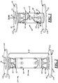
- FIG. 1 illustrates a portion of a fuel tank 10 (in a parison form) and a stiffening assembly 12 coupling two portions 14, 16 of a fuel tank wall 18.
- the stiffening assembly 12 provides structural support for the fuel tank 10 and minimizes deformation of the shape of the fuel tank (e.g., due to temperature changes, pressure changes, or both).
- the fuel tank wall 18 defines an enclosed volume or interior 20 for carrying liquid fuel.
- the wall 18 may have any suitable thickness; further, the thickness of the wall may vary depending on the location in the tank 10.
- the tank may be comprised of any suitable material, such as (but not limited to) a multi-layer plastic construction having one or more structural layers, one or more adhesive layers, and one or more vapor barrier layers.
- the stiffening assembly 12 comprises two or more inserts 30 and a connecting assembly 32.
- the inserts 30 are carried by the fuel tank wall 18, and the connecting assembly 32 spans between and couples one insert to the other thereby stiffening or supporting two connected or adjoined regions or portions 14, 16 of the fuel tank wall.
- the inserts 30 may be identical; therefore, only one will be described below.
- the insert 30 has a base 36, a reduced diameter neck 38 axially extending from the base, and a head 42 extending from the neck.
- the illustrated base has a generally annular shape and is partially defined by a radially outwardly extending flange 46.
- the periphery of the flange 46 is circular; however, the base 36 and/or flange 46 may have different shapes as desired.
- at least a portion of the flange 46 is radially wider than a portion of the neck 38.
- the neck 38 may radially narrow as it extends axially from the base 36, providing a generally conical or frustoconical shape. Or as in the illustrated embodiment, the neck may be curved between the base and head providing a partially hyperbolic shape. In some implementations, at least a portion of the neck 38 is radially narrower than a portion of the head 42.
- the neck 38 may be circumferentially continuous, if desired, or it may have recesses or other voids formed in it to improve connection of the tank to the insert 30.
- the head 42 is connected to the neck 38 extending axially away therefrom, and at least a portion of the head 42 may be radially wider than at least a portion of the neck 38 adjacent to the head.
- the head is generally spherical; however again, this is merely an example. Other shapes are possible.
- the head 42 may have one or more voids 52 at a distal end 54.
- the voids 52 may be cavities or blind holes, through holes, or any combination thereof.
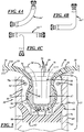
- the cross-section shown in FIG. 5 illustrates the voids 52 as blind holes.
- the base 36, neck 38, and head 42 of the insert may be integrally formed in one piece of material, such as by molding (e.g., a unibody construction).
- the insert 30 is formed of a polymeric, composite, or metal material.
- the insert 30 may be at least partially hollow - having a cavity 56 opening at one side 41 of the base and extending towards the head 42 (see also FIG. 5 ).
- the cavity 56 may be used to carry the insert 30 in a manufacturing mold so that the insert may be incorporated into a parison of the fuel tank 10.
- the cavity may be any suitable shape; and in some implementations, the insert 30 may not have a cavity.
- FIG. 5 further illustrates that the insert 30 may have one or more ribs 58 that extend inwardly and define part of the cavity 56.
- the ribs 58 may extend at least partially circumferentially and/or at least partially from the base 36 towards the head 42.
- the insert 30 may include cavities or other voids, including openings therethrough, in one or more of the base 36, neck 38, and head 42 to facilitate connection of the insert to the fuel tank wall 18.
- the insert may comprise one or more circumferentially-spaced through holes 50 on the base 36 to further facilitate bonding of the insert to the parison fuel tank during manufacturing.
- Other embodiments do not comprise holes 50.
- the insert 30 is adapted to cooperate with the connecting assembly 32 to interconnect spaced apart portions 14, 16 of the fuel tank wall.
- the connecting assembly 32 includes a cylindrical, tubular body 64 extending from a first end 66 to a second end 68 and two couplers 62. Each end 66, 68 may have an opening 70a, 70b extending from the respective end axially inwardly.
- the body 64 is hollow and the openings 70a, 70b are in communication with one another; however, this is not required.
- One or more circumferentially spaced detent elements 76 may be provided in the body 64 at or adjacent to the first end 66 and one or more similar detent elements may be provided at or adjacent to the second end 68. For example, in the illustrated embodiment, six circumferentially spaced detent elements 76 are shown at each end.
- the detent elements 76 are shown as circular through-holes; however, this is merely an example and other implementations are possible - e.g., the elements 76 need not be circular nor need the elements pass entirely through the support body 64 (e.g., the element 76 may be a cavity or depression extending radially outwardly from an inner surface 78 of the body 64. Or for example, the detent elements could be inwardly extending protrusions adapted to couple to openings or cavities on the connectors 62.
- the body 64 is straight; however, other implementations also exist (see FIGS. 4A, 4B, 4C having support bodies 64', 64", 64"', respectively).
- the support may be curved or angled. It may have a T-shape, a Y-shape, a cross-shape, an X-shape, etc. (e.g., having three or more openings and passages). These of course are examples, and other embodiments also exist.
- a separate connector 62 is coupled to each end 66, 68 of the body 64, and the connectors at each end 66, 68 of the body may be identical, so only one connector 62 will be described in detail hereafter.
- the connector 62 comprises a collar 80, a first coupler 82 and a second coupler 84.
- the first coupler 82 is adapted to interconnect the connector 62 and the fuel tank 12 while the second coupler 84 is adapted to interconnect the connector 62 to the body 64.
- the collar 80 is sized to be received within the opening 70a (or 70b) by a sliding or interference fit.
- the collar 80 is shown having an annular, cylindrical shape, but of course, other shapes are also possible.
- the first coupler 82 includes one or more fingers 86 attached at one end 90 to and extending from the collar 80 to a free end 94 (six fingers are shown, although any number may be used).
- the fingers may extend generally axially from the collar and may be radially inclined so that the free ends 94 extend radially outwardly relative to the collar 80.
- the fingers 86 may also be flexible, or pivoted relative to the collar 80, such as about a living hinge defined at the fixed end 90, so that the free ends 94 may move radially inwardly.
- the fingers 86 may have a first state where the distance between the inner surfaces of the free ends of the fingers is greater than in a second state of the fingers when at least a portion of the fingers are flexed or moved inwardly.
- the fingers 86 include a narrow portion 88 at the fixed end 90 leading to a wider portion 92 that defines the free end 94.
- Each finger 86 may be provided in or biased to a radially outwardly position and is flexible to move inwardly when a sufficient force is applied to it.
- the six fingers 86 may be evenly, circumferentially spaced around the collar 80.
- the inner surface of each finger may be concave so that the fingers collectively define a pocket 96 (see also FIG. 5 ).
- the pocket 96 is adapted to receive at least a portion of the head 42 of the insert 30, as will be described later.
- the second coupler 84 includes multiple protrusions 100 also carried by and, in at least some implementations, cantilevered from the collar 80 so that they have a fixed end 102 and a free end 104 (six protrusions are shown although any number may be used).
- the protrusions may be evenly spaced around the collar and may be alternated with the fingers 86, if desired. Of course, other arrangements may be used as desired.
- the protrusions 100 may extend axially and radially outwardly from their fixed ends 102 toward their free ends 104.
- each protrusion 100 terminate where the wider portion 92 of the fingers 86 begin and a gap 106 is provided surrounding the protrusions 100 so that the protrusions are generally independent of the fingers.
- each protrusion 100 is provided in or biased to a radially outwardly inclined position having at least a portion that extends radially outwardly farther than the adjacent portion of the fingers 86.
- Each protrusion 100 may be flexible so that at least a portion is moveable or may be bent radially inwardly; e.g., flexing at or near the collar 80, such as about a living hinge provided between the collar 80 and protrusion 100.
- each protrusion may be resilient to return radially outwardly at least partially back to its unflexed position when a force on the protrusion is sufficiently reduced or removed.
- FIGS. 1-3 collectively illustrate at least a portion of a manufacturing process for a fuel tank.
- the tank 10 and its wall 18 may be molded from a polymeric material in a mold having two halves that define a mold cavity that defines the outer shape of the fuel tank.
- the mold halves may be opened and the inserts 30 may be positioned within the mold halves before the polymeric material is provided into the mold cavity.
- the inserts 30 are oriented with the base 36 and/or cavity 56 engaged with or carried by each mold half and the head 42 extending inwardly into the mold cavity.
- the inserts 30 may be provided in pairs, with a first insert carried by one mold half and a second insert carried by the other mold half and aligned with the first insert. Hence, when the mold halves are closed together to define the mold cavity, the inserts 30 are moved toward each other and remain aligned (in at least some implementations).
- An extruded parison used to form the fuel tank may be provided into the mold, between the separated mold halves.
- the mold halves may be at least partially closed and pressurized gas (e.g., air) may be provided into an interior of the parison using a blow pin to pre-blow the parison outwardly into the mold cavity.
- pressurized gas e.g., air
- the head 42 and neck 38 of the inserts 30 may be covered with the parison material which conforms to their shape, and the base 36 may be at least partially embedded therein.
- the expansion may shape at least a portion of the tank wall 18 so that each of the inserts 30 define a projection that extends at least partially radially inwardly into the tank interior.
- projections may be defined by the size and shape of the head 42, the neck 38, and/or even the base 36, as well as well as the thickness of the parison; thus, for example, the projections may have any desired diameter(s) (and varying diameters/shape), inwardly extending length, etc.
- the parison material may separated into parison halves or portions, such as by cutting or tearing the parison, with one parison half in each mold half.
- the mold halves then may be opened to expose the interior of the parison halves. This provides access to the interior of the parison so that fuel tank components, such as the connecting assembly 32, may be located within the interior of the parison.
- One such method of forming a parison and separating a parison into parison halves in order to locate components therein is disclosed in U.S. Patent Application Serial Number 12/491,964 , the disclosure of which is incorporated by reference herein in its entirety.
- the connecting assembly 32 is introduced between the mold halves and the parison halves.
- the connectors 62 are provided in an initial assembly position, as shown in FIG. 2 .
- the collars 80 are at least partially received within the connector tube openings 70a, 70b, optionally with the protrusions 100 received within the respective opening, displaced inwardly and frictionally engaged with the inner surface 78 of the tubular body 64.
- the connecting assembly 32 is positioned between the mold halves with the pockets 96 defined by the connector fingers 86 being aligned with the heads 42 of the inserts 30.
- the connecting assembly 32 may be held in this position on an arm (e.g., a robot arm) or other actuator holding the connector assembly 32 until the connectors 62 initially receive the heads 42 between the free ends 94 of the fingers 86, and then the arm may be withdrawn from between the mold halves so that the mold may be further and eventually, fully closed.
- an arm e.g., a robot arm
- actuator holding the connector assembly 32 until the connectors 62 initially receive the heads 42 between the free ends 94 of the fingers 86, and then the arm may be withdrawn from between the mold halves so that the mold may be further and eventually, fully closed.
- the heads 42 of the inserts 30 are received within the pockets 96 of the connectors 62 and the free ends 94 of the fingers 86 eventually engage the tank material overlying the base 36.
- Further closing of the mold presses the connectors 62 into the tubular body 64 simultaneously at each end 66, 68, and radially inwardly flexes the fingers 86 as the fingers are increasingly received within the body 64.
- the protrusions 100 are aligned with the detent elements 76 and the protrusions 100 resiliently return radially outwardly to or toward their initial state such that a portion of the protrusions 100 extends outwardly into or through the detent elements 76.
- the fingers 86 are received within the body 64 sufficiently to radially inwardly displace the fingers sufficiently so that the fingers radially overlap the heads 42 of the inserts 30 so that the heads are trapped within the pockets 96 defined in the connectors 62.
- the components remain in this position as the parison material is finally formed (e.g. final blow pressure is applied within the parison interior). The material hardens and the formed fuel tank 10 is removed from the mold.
- the stress on the tank 10 from such forces is experienced over a relatively large surface area at the interface between the insert base 36 and the tank wall 18 to prevent undue stress on any portion of the fuel tank.
- the forces on the tank wall can be further dissipated, as desired for a particular application.
- forces tending to separate the fuel tank walls 18 e.g. expand the fuel tank outwardly
- temperature increases both ambient temperature outside of the fuel tank 10 and the temperature within the fuel tank
- the fuel tank 10 with the stiffening assembly 12 may be used to contain fluid at increased pressures and/or with increased temperatures compared to tanks without such stiffening or connecting features. And, due to the increased stiffness and rigidity of the fuel tank provided by the stiffening assembly 12, a thinner fuel tank wall 18 can be used in applications compared to fuel tanks 10 without the assembly 12, which may lead to a cost savings and, in some instances, a weight savings.
- a fuel tank may be formed from an uncut or undivided cylindrical parison introduced between two open mold halves each carrying an insert 30, similar to that described above.
- An arm may introduce a carrier carrying the connecting assembly 32 through an open end of the parison aligning the connectors 62 with the inserts 30.
- the mold halves may be partially closed, an opposing end of the parison may be at least partially closed using a gripper mechanism, and pressurized air may be provided into the parison to initially and partially expand it.
- the mold halves may be partially closed until the connectors 62 at least partially receive the heads 42 of the inserts 30, as described above.
- the arm may be removed leaving the carrier and connecting assembly 32 in place, and then, the mold halves may be fully closed fully engaging the connecting assembly with the inserts 30, having the parison trapped therebetween.
- additional pressurized air may be provided into the parison - e.g., to maintain the parison open and prevent it from collapsing and to form the parison into the desired fuel tank shape.
- a fuel tank may be formed from sheets of material, such as in a vacuum forming or other type of process. With mold halves opened, material may be provided into both mold halves, overlapping the inserts 30. The material may then be formed into the cavities such as by vacuum forming. As described above, the connecting assembly 32 may be provided between the mold halves before they are closed so that the connecting assembly 32 is coupled to the inserts 30 as the mold halves close to form the fuel tank.
- the connecting assembly 32 is provided into a fuel tank and coupled thereto after the tank is formed.
- the tank is formed by overmolding the inserts 30 as described above. Once the tank material has hardened, the connecting assembly 32 may be located within the interior 20 of the tank such as by being inserted through a hole in the tank wall 18.
- the fuel tank walls 18 may be separated sufficiently to permit the connecting assembly 32 to be received between the portions 14, 16 of the tank wall that overlie the inserts 30 - the connectors 62 not being fully received within the tubular body 64.
- the connectors 62 may be aligned with the inserts 30.
- the fuel tank wall portions may be moved closer together to push each connector 62 into the tubular body 64 while also engaging the heads 42 of the inserts 30 into the body 64 of the connecting assembly 32, similar to that described above.
Landscapes
- Engineering & Computer Science (AREA)
- Mechanical Engineering (AREA)
- Life Sciences & Earth Sciences (AREA)
- Sustainable Development (AREA)
- Sustainable Energy (AREA)
- Chemical & Material Sciences (AREA)
- Combustion & Propulsion (AREA)
- Transportation (AREA)
- Manufacturing & Machinery (AREA)
- Cooling, Air Intake And Gas Exhaust, And Fuel Tank Arrangements In Propulsion Units (AREA)
- Blow-Moulding Or Thermoforming Of Plastics Or The Like (AREA)
Description
- The present disclosure relates generally to a structure supporting a fuel tank under pressure.
- Fuel tanks for automotive vehicles have been made from metal and plastic materials. Fuel tanks are formed in various sizes and shapes as required for the various applications in which they are used. Fuel tanks used in passenger vehicles must meet certain requirements relating to, for example, resistance to rupture upon impact and permeability to hydrocarbons in fuel vapor. Typical plastic fuel tanks include a single wall of material and that wall may be formed from a single material or multiple layers of different materials. Particularly in fuel tanks, there is a need to make containers having more than one wall or layer of different materials in order to meet various requirements, for example with respect to mechanical stability and resistance to higher pressures in modern systems. Up to now the making of such containers requires complex multi-step manufacturing methods.
DE 10 2011 015 049 discloses a stiffening assembly using two screws for fixing a stiffening element to a tank.EP 2 754 581 discloses stiffening assembly for such fuel tank.US 2003/0141304 discloses a clip for attaching a component to a tank. - The present disclosure provides a stiffening assembly for a fuel tank. The stiffening assembly includes first and second inserts for the wall of a fuel tank, and an elongate coupler. The inserts each comprise a base having flange, a head, and a neck coupling the base to the head. The neck may have a portion that is narrower than at least a portion of the head. The elongate body has first and second couplers at respective first and second ends of the body, each coupler including a pocket sized to receive the head of a respective one of the inserts. The insert may be partially hollow and may include a cavity opening at the base. Alternatively, the elongate body may define first and second openings at the first and second ends, the first and second openings receiving the first and second couplers, wherein the pockets are defined by a plurality of fingers, the plurality of fingers being moveable between a first state and a second state, the plurality of fingers moving radially inwardly from the first state to the second state, the first and second openings sized to cause the plurality of fingers to move to the second state as the fingers are received within the openings.
- According to more detailed aspects, each insert may be integrally formed in one piece. The heads of the inserts may include voids at their distal ends. The inserts may include ribs projecting into the cavity. The couplers can be separately formed and attached to the elongate body, the couplers and body including corresponding tabs and detents for attachment. The elongate member may include two tubular members defining the first and second ends and at least a third end, wherein the stiffening assembly further comprises a third insert and a third coupler at the third end.
- A fuel tank assembly according to the present disclosure includes a fuel tank having a wall defining a tank interior, and a stiffening assembly as described herein. A first exterior portion of the tank wall carries the first insert and a second exterior portion of the wall carries the second insert, and wherein the body and couplers are received within the tank interior. Here, the wall may be interposed between the inserts and the couplers.
- The present disclosure also provides a method of manufacturing a fuel tank. The method may include the steps of forming a fuel tank, wherein the tank carries at least a first and second insert, locating a rigid body within the tank interior, aligned with the first and second inserts, the body including a first connector and a second connector, and coupling at least a portion of the first insert with the first connector and at least a portion of the second insert with the second connector. The body spans between two spaced apart wall portions of the tank to limit movement of the two wall portions relative to each other.
- According to more detailed aspects, the forming step may further comprise overmolding the insert while the fuel tank is in a parison form. The forming step may also further comprise shaping a tank wall carrying the insert so that the insert defines a projection that extends at least partially radially inwardly into a tank interior. In one form, the fuel tank is formed in a mold having portions moveable between open and closed positions, and the step of coupling the insert with the first connector is accomplished by movement of the mold portions toward their closed position. The interior of the parison may be accessed during the tank forming process to allow insertion of the body into the parison interior, e.g. by cutting or tearing the parison into two portions. The method may also include the step of coupling the first and second connectors to the body. The first connector may be coupled to the body simultaneously with coupling the first connector to the first insert.
- The following detailed description of preferred embodiments and best mode will be set forth with reference to the accompanying drawings, in which:
-
FIG. 1 is an exploded view of a portion of a fuel tank and a stiffening assembly within the fuel tank; -
FIG. 2 is a perspective view of the stiffening assembly ofFIG. 1 in a partially assembled state; -
FIG. 3 is a perspective view of the stiffening assembly ofFIG. 1 in a fully assembled state; -
FIGS. 4A-4C illustrate additional embodiments of the stiffening assembly; and -
FIG. 5 is a partial, cross-sectional view of a portion of the stiffening assembly and part of a fuel tank wall along section lines 5-5 ofFIG. 3 . - Referring in more detail to the drawings,
FIG. 1 illustrates a portion of a fuel tank 10 (in a parison form) and astiffening assembly 12 coupling twoportions fuel tank wall 18. Thestiffening assembly 12 provides structural support for thefuel tank 10 and minimizes deformation of the shape of the fuel tank (e.g., due to temperature changes, pressure changes, or both). - The
fuel tank wall 18 defines an enclosed volume or interior 20 for carrying liquid fuel. Thewall 18 may have any suitable thickness; further, the thickness of the wall may vary depending on the location in thetank 10. And the tank may be comprised of any suitable material, such as (but not limited to) a multi-layer plastic construction having one or more structural layers, one or more adhesive layers, and one or more vapor barrier layers. - The
stiffening assembly 12 comprises two ormore inserts 30 and a connectingassembly 32. As will be explained below, theinserts 30 are carried by thefuel tank wall 18, and the connectingassembly 32 spans between and couples one insert to the other thereby stiffening or supporting two connected or adjoined regions orportions - The
inserts 30 may be identical; therefore, only one will be described below. Theinsert 30 has abase 36, a reduceddiameter neck 38 axially extending from the base, and ahead 42 extending from the neck. The illustrated base has a generally annular shape and is partially defined by a radially outwardly extendingflange 46. In one embodiment, the periphery of theflange 46 is circular; however, thebase 36 and/orflange 46 may have different shapes as desired. In at least some implementations, at least a portion of theflange 46 is radially wider than a portion of theneck 38. - The
neck 38 may radially narrow as it extends axially from thebase 36, providing a generally conical or frustoconical shape. Or as in the illustrated embodiment, the neck may be curved between the base and head providing a partially hyperbolic shape. In some implementations, at least a portion of theneck 38 is radially narrower than a portion of thehead 42. Theneck 38 may be circumferentially continuous, if desired, or it may have recesses or other voids formed in it to improve connection of the tank to theinsert 30. - The
head 42 is connected to theneck 38 extending axially away therefrom, and at least a portion of thehead 42 may be radially wider than at least a portion of theneck 38 adjacent to the head. In the implementation shown, the head is generally spherical; however again, this is merely an example. Other shapes are possible. Thehead 42 may have one ormore voids 52 at adistal end 54. Thevoids 52 may be cavities or blind holes, through holes, or any combination thereof. For example, the cross-section shown inFIG. 5 illustrates thevoids 52 as blind holes. - The
base 36,neck 38, andhead 42 of the insert may be integrally formed in one piece of material, such as by molding (e.g., a unibody construction). In at least one implementation, theinsert 30 is formed of a polymeric, composite, or metal material. - The
insert 30 may be at least partially hollow - having acavity 56 opening at oneside 41 of the base and extending towards the head 42 (see alsoFIG. 5 ). As will be described in greater detail below, thecavity 56 may be used to carry theinsert 30 in a manufacturing mold so that the insert may be incorporated into a parison of thefuel tank 10. The cavity may be any suitable shape; and in some implementations, theinsert 30 may not have a cavity. -
FIG. 5 further illustrates that theinsert 30 may have one ormore ribs 58 that extend inwardly and define part of thecavity 56. To reinforce the strength of theinsert 30, theribs 58 may extend at least partially circumferentially and/or at least partially from the base 36 towards thehead 42. - The
insert 30 may include cavities or other voids, including openings therethrough, in one or more of thebase 36,neck 38, andhead 42 to facilitate connection of the insert to thefuel tank wall 18. For example, according to one embodiment shown inFIG. 5 , the insert may comprise one or more circumferentially-spaced throughholes 50 on the base 36 to further facilitate bonding of the insert to the parison fuel tank during manufacturing. Other embodiments do not comprise holes 50. Theinsert 30 is adapted to cooperate with the connectingassembly 32 to interconnect spaced apartportions - Returning to
FIG. 1 , the connectingassembly 32 includes a cylindrical,tubular body 64 extending from afirst end 66 to asecond end 68 and twocouplers 62. Eachend opening body 64 is hollow and theopenings detent elements 76 may be provided in thebody 64 at or adjacent to thefirst end 66 and one or more similar detent elements may be provided at or adjacent to thesecond end 68. For example, in the illustrated embodiment, six circumferentially spaceddetent elements 76 are shown at each end. Thedetent elements 76 are shown as circular through-holes; however, this is merely an example and other implementations are possible - e.g., theelements 76 need not be circular nor need the elements pass entirely through the support body 64 (e.g., theelement 76 may be a cavity or depression extending radially outwardly from aninner surface 78 of thebody 64. Or for example, the detent elements could be inwardly extending protrusions adapted to couple to openings or cavities on theconnectors 62. - In
FIG. 1 , thebody 64 is straight; however, other implementations also exist (seeFIGS. 4A, 4B, 4C havingsupport bodies 64', 64", 64"', respectively). For example, the support may be curved or angled. It may have a T-shape, a Y-shape, a cross-shape, an X-shape, etc. (e.g., having three or more openings and passages). These of course are examples, and other embodiments also exist. - As shown in
FIGS. 1-3 , in at least one embodiment, aseparate connector 62 is coupled to eachend body 64, and the connectors at eachend connector 62 will be described in detail hereafter. Theconnector 62 comprises acollar 80, afirst coupler 82 and asecond coupler 84. Thefirst coupler 82 is adapted to interconnect theconnector 62 and thefuel tank 12 while thesecond coupler 84 is adapted to interconnect theconnector 62 to thebody 64. Thecollar 80 is sized to be received within theopening 70a (or 70b) by a sliding or interference fit. Thecollar 80 is shown having an annular, cylindrical shape, but of course, other shapes are also possible. - In the illustrated embodiment, the
first coupler 82 includes one ormore fingers 86 attached at oneend 90 to and extending from thecollar 80 to a free end 94 (six fingers are shown, although any number may be used). The fingers may extend generally axially from the collar and may be radially inclined so that the free ends 94 extend radially outwardly relative to thecollar 80. Thefingers 86 may also be flexible, or pivoted relative to thecollar 80, such as about a living hinge defined at thefixed end 90, so that the free ends 94 may move radially inwardly. Hence, thefingers 86 may have a first state where the distance between the inner surfaces of the free ends of the fingers is greater than in a second state of the fingers when at least a portion of the fingers are flexed or moved inwardly. In the implementation shown, thefingers 86 include anarrow portion 88 at thefixed end 90 leading to awider portion 92 that defines thefree end 94. Eachfinger 86 may be provided in or biased to a radially outwardly position and is flexible to move inwardly when a sufficient force is applied to it. The sixfingers 86 may be evenly, circumferentially spaced around thecollar 80. The inner surface of each finger may be concave so that the fingers collectively define a pocket 96 (see alsoFIG. 5 ). Thepocket 96 is adapted to receive at least a portion of thehead 42 of theinsert 30, as will be described later. - In the illustrated embodiment, the
second coupler 84 includesmultiple protrusions 100 also carried by and, in at least some implementations, cantilevered from thecollar 80 so that they have a fixedend 102 and a free end 104 (six protrusions are shown although any number may be used). The protrusions may be evenly spaced around the collar and may be alternated with thefingers 86, if desired. Of course, other arrangements may be used as desired. Like thefingers 86, theprotrusions 100 may extend axially and radially outwardly from their fixed ends 102 toward their free ends 104. In one embodiment, theprotrusions 100 terminate where thewider portion 92 of thefingers 86 begin and agap 106 is provided surrounding theprotrusions 100 so that the protrusions are generally independent of the fingers. In at least one embodiment, eachprotrusion 100 is provided in or biased to a radially outwardly inclined position having at least a portion that extends radially outwardly farther than the adjacent portion of thefingers 86. Eachprotrusion 100 may be flexible so that at least a portion is moveable or may be bent radially inwardly; e.g., flexing at or near thecollar 80, such as about a living hinge provided between thecollar 80 andprotrusion 100. And each protrusion may be resilient to return radially outwardly at least partially back to its unflexed position when a force on the protrusion is sufficiently reduced or removed. -
FIGS. 1-3 collectively illustrate at least a portion of a manufacturing process for a fuel tank. In one embodiment, thetank 10 and itswall 18 may be molded from a polymeric material in a mold having two halves that define a mold cavity that defines the outer shape of the fuel tank. In the fuel tank forming process, the mold halves may be opened and theinserts 30 may be positioned within the mold halves before the polymeric material is provided into the mold cavity. In at least some implementations, theinserts 30 are oriented with thebase 36 and/orcavity 56 engaged with or carried by each mold half and thehead 42 extending inwardly into the mold cavity. Theinserts 30 may be provided in pairs, with a first insert carried by one mold half and a second insert carried by the other mold half and aligned with the first insert. Hence, when the mold halves are closed together to define the mold cavity, theinserts 30 are moved toward each other and remain aligned (in at least some implementations). - An extruded parison used to form the fuel tank may be provided into the mold, between the separated mold halves. Next, the mold halves may be at least partially closed and pressurized gas (e.g., air) may be provided into an interior of the parison using a blow pin to pre-blow the parison outwardly into the mold cavity. During the expansion, the
head 42 andneck 38 of theinserts 30 may be covered with the parison material which conforms to their shape, and the base 36 may be at least partially embedded therein. Thus, the expansion may shape at least a portion of thetank wall 18 so that each of theinserts 30 define a projection that extends at least partially radially inwardly into the tank interior. These projections may be defined by the size and shape of thehead 42, theneck 38, and/or even thebase 36, as well as well as the thickness of the parison; thus, for example, the projections may have any desired diameter(s) (and varying diameters/shape), inwardly extending length, etc. - Thereafter, the parison material may separated into parison halves or portions, such as by cutting or tearing the parison, with one parison half in each mold half. The mold halves then may be opened to expose the interior of the parison halves. This provides access to the interior of the parison so that fuel tank components, such as the connecting
assembly 32, may be located within the interior of the parison. One such method of forming a parison and separating a parison into parison halves in order to locate components therein is disclosed inU.S. Patent , the disclosure of which is incorporated by reference herein in its entirety.Application Serial Number 12/491,964 - With the mold opened, the connecting
assembly 32 is introduced between the mold halves and the parison halves. Here, theconnectors 62 are provided in an initial assembly position, as shown inFIG. 2 . In this initial position, thecollars 80 are at least partially received within theconnector tube openings protrusions 100 received within the respective opening, displaced inwardly and frictionally engaged with theinner surface 78 of thetubular body 64. In this initial assembly position, the connectingassembly 32 is positioned between the mold halves with thepockets 96 defined by theconnector fingers 86 being aligned with theheads 42 of theinserts 30. The connectingassembly 32 may be held in this position on an arm (e.g., a robot arm) or other actuator holding theconnector assembly 32 until theconnectors 62 initially receive theheads 42 between the free ends 94 of thefingers 86, and then the arm may be withdrawn from between the mold halves so that the mold may be further and eventually, fully closed. - While the mold halves close, the
heads 42 of theinserts 30 are received within thepockets 96 of theconnectors 62 and the free ends 94 of thefingers 86 eventually engage the tank material overlying thebase 36. Further closing of the mold presses theconnectors 62 into thetubular body 64 simultaneously at eachend fingers 86 as the fingers are increasingly received within thebody 64. Upon full closure of the mold, as shown inFIG. 3 , theprotrusions 100 are aligned with thedetent elements 76 and theprotrusions 100 resiliently return radially outwardly to or toward their initial state such that a portion of theprotrusions 100 extends outwardly into or through thedetent elements 76. Also, thefingers 86 are received within thebody 64 sufficiently to radially inwardly displace the fingers sufficiently so that the fingers radially overlap theheads 42 of theinserts 30 so that the heads are trapped within thepockets 96 defined in theconnectors 62. The components remain in this position as the parison material is finally formed (e.g. final blow pressure is applied within the parison interior). The material hardens and the formedfuel tank 10 is removed from the mold. - In this position, outward movement of the
fingers 86 is prevented by the overlappingtubular body 64, and movement of the body relative to theconnectors 62 is prevented by engagement of theprotrusions 100 with thebody 64 from within thedetent elements 76. In this way, thehead 42 of eachinsert 30 remains trapped in an associatedpocket 96, and thefuel tank wall 18 portions remain interconnected. So connected, theportions assembly 32 are inhibited or prevented from any significant movement away from or toward each other. This is due at least in part to thefuel tank wall 18 being securely trapped between therespective heads 42 of theinserts 30 and theconnectors 62 such that forces tending to separate the fuel tank walls are transferred to the tubular body 64 (via theinserts 30 and connectors 62) which may be rigid and substantially inextensible. - Further, the stress on the
tank 10 from such forces is experienced over a relatively large surface area at the interface between theinsert base 36 and thetank wall 18 to prevent undue stress on any portion of the fuel tank. By increasing the surface area of theflange 46, the forces on the tank wall can be further dissipated, as desired for a particular application. By way of example, forces tending to separate the fuel tank walls 18 (e.g. expand the fuel tank outwardly) may occur due to increased pressure within the tank, or the weight of fuel in a full tank acting on the fuel tank wall. Further, temperature increases (both ambient temperature outside of thefuel tank 10 and the temperature within the fuel tank) can decrease the stiffness, rigidity, or strength of a polymeric fuel tank. Therefore, thefuel tank 10 with the stiffeningassembly 12 may be used to contain fluid at increased pressures and/or with increased temperatures compared to tanks without such stiffening or connecting features. And, due to the increased stiffness and rigidity of the fuel tank provided by the stiffeningassembly 12, a thinnerfuel tank wall 18 can be used in applications compared tofuel tanks 10 without theassembly 12, which may lead to a cost savings and, in some instances, a weight savings. - The above described process is one example of a fuel tank formation process. Other processes may be used to form a fuel tank with the stiffening
assembly 12 therein. For example, a fuel tank may be formed from an uncut or undivided cylindrical parison introduced between two open mold halves each carrying aninsert 30, similar to that described above. An arm may introduce a carrier carrying the connectingassembly 32 through an open end of the parison aligning theconnectors 62 with theinserts 30. The mold halves may be partially closed, an opposing end of the parison may be at least partially closed using a gripper mechanism, and pressurized air may be provided into the parison to initially and partially expand it. The mold halves may be partially closed until theconnectors 62 at least partially receive theheads 42 of theinserts 30, as described above. Thereafter, the arm may be removed leaving the carrier and connectingassembly 32 in place, and then, the mold halves may be fully closed fully engaging the connecting assembly with theinserts 30, having the parison trapped therebetween. During this process, and even after the mold is fully closed, additional pressurized air may be provided into the parison - e.g., to maintain the parison open and prevent it from collapsing and to form the parison into the desired fuel tank shape. Other aspects of this method are disclosed inU.S. Patent Number 6,712,234 , the disclosure of which is incorporated by reference herein in its entirety. - In another assembly example, a fuel tank may be formed from sheets of material, such as in a vacuum forming or other type of process. With mold halves opened, material may be provided into both mold halves, overlapping the
inserts 30. The material may then be formed into the cavities such as by vacuum forming. As described above, the connectingassembly 32 may be provided between the mold halves before they are closed so that the connectingassembly 32 is coupled to theinserts 30 as the mold halves close to form the fuel tank. - In another example, the connecting
assembly 32 is provided into a fuel tank and coupled thereto after the tank is formed. In this embodiment, the tank is formed by overmolding theinserts 30 as described above. Once the tank material has hardened, the connectingassembly 32 may be located within theinterior 20 of the tank such as by being inserted through a hole in thetank wall 18. - Next, the
fuel tank walls 18 may be separated sufficiently to permit the connectingassembly 32 to be received between theportions connectors 62 not being fully received within thetubular body 64. Theconnectors 62 may be aligned with theinserts 30. Then, the fuel tank wall portions may be moved closer together to push eachconnector 62 into thetubular body 64 while also engaging theheads 42 of theinserts 30 into thebody 64 of the connectingassembly 32, similar to that described above. Once thecoupler 82 is engaged to the insert heads 42 and thecoupler 84 is engaged with thebody 64, the assembly is complete.
Claims (17)
- A stiffening assembly (12) for a fuel tank (10) having a wall (18), the assembly (12) comprising:first and second inserts (30) for the wall (18) of the fuel tank (10), the inserts (30) each comprising a base (36) having a flange (46), a head (42), and a neck (38) coupling the base (36) to the head (42), the neck (38) having a portion that is narrower than at least a portion of the head (42); andan elongate body (64) having first and second connectors (62) at respective first and second ends (66, 68) of the body (64), each connector (62) including a pocket (96) sized to receive the head (42) of a respective one of the inserts (30), whereby the insert (30) is partially hollow and includes a cavity (56) opening at the base (36).
- The stiffening assembly of Claim 1, wherein each insert (30) is integrally formed in one piece.
- The stiffening assembly of Claim 1, wherein the heads (42) of the inserts (30) each include voids (52) at its distal end (54).
- The stiffening assembly of Claim 1, wherein the inserts (30) include ribs (58) projecting into the cavity.
- The stiffening assembly of Claim 1, wherein the connectors (62) are separately formed and attached to the elongate body (64), the connectors (62) and body (64) including corresponding tabs and detents (76) for attachment.
- The stiffening assembly of Claim 1, wherein the elongate body (64) defines first and second openings (70a, 70b) at the first and second ends (66, 68), the first and second openings (70a, 70b) receiving the first and second connectors (62).
- The stiffening assembly of Claim 1, wherein the elongate body (64"') includes two tubular members defining the first and second ends and at least a third end, and further comprising a third insert and a third coupler at the third end.
- A stiffening assembly (12) for a fuel tank (10) having a wall (18), the assembly (12) comprising:
first and second inserts (30) for the wall (18) of the fuel tank (10), the inserts (30) each comprising a base (36) having a flange (46), a head (42), and a neck (38) coupling the base (36) to the head (42), the neck (38) having a portion that is narrower than at least a portion of the head (42); and an elongate body (64) having first and second connectors (62) at respective first and second ends (66, 68) of the body (64), each connector (62) including a pocket (96) sized to receive the head (42) of a respective one of the inserts (30), and wherein the elongate body (64) defines first and second openings (70a, 70b) at the first and second ends (66, 68), the first and second openings (70a, 70b) receiving the first and second connectors (62), whereby the pockets (96) are defined by a plurality of fingers (86), the plurality of fingers (86) being moveable between a first state and a second state, the plurality of fingers (86) moving radially inwardly from the first state to the second state, the first and second openings (70a, 70b) sized to cause the plurality of fingers (86) to move to the second state as the fingers (86) are received within the openings (70a, 70b). - A fuel tank assembly comprising:a fuel tank (10) having a wall (18) defining a tank interior; andthe stiffening assembly (12) of claim 1 or 8, wherein a first exterior portion (14) of the wall (18) carries the first insert (30) and a second exterior portion (16) of the wall (18) carries the second insert (30), and wherein the body (64) and connectors (62) are received within the tank interior.
- The fuel tank assembly of Claim 9, wherein the wall (18) is interposed between the inserts (30) and the connectors (62).
- A method of manufacturing a fuel tank (10), comprising the steps of:forming a fuel tank (10), wherein the tank (10) carries at least a first and second insert (30);locating a rigid body (64) within the tank interior, aligned with the first and second inserts (30), the body (64) including a first connector (62) and a second connector (62); andcoupling at least a portion of the first insert (30) with the first connector (62) and at least a portion of the second insert (30) with the second connector (62), and wherein the body (64) spans between two spaced apart wall portions (14, 16) of the tank (10) to limit movement of the two wall portions (14, 16) relative to each other.
- The method of Claim 11, wherein the forming step further comprises overmolding the insert (30) while the fuel tank (10) is in a parison form.
- The method of Claim 12, wherein the forming step further comprises shaping a tank wall (18) carrying the insert (30) so that the insert (30) defines a projection that extends at least partially radially inwardly into a tank (10) interior.
- The method of Claim 11, wherein the fuel tank (10) is formed in a mold having portions moveable between open and closed positions, and the step of coupling the insert (30) with the first connector (62) is accomplished by movement of the mold portions toward their closed position.
- The method of Claim 11, wherein the interior of the parison may be accessed during the tank (10) forming process to allow insertion of the body (64) into the parison interior.
- The method of Claim 11, further comprising the step of coupling the first and second connectors (62) to the body (64).
- The method of Claim 16, wherein the first connector (62) is coupled to the body (64) simultaneously with coupling the first connector (62) to the first insert (30).
Applications Claiming Priority (2)
| Application Number | Priority Date | Filing Date | Title |
|---|---|---|---|
| US201562106404P | 2015-01-22 | 2015-01-22 | |
| PCT/EP2016/051314 WO2016116590A1 (en) | 2015-01-22 | 2016-01-22 | Stiffening assembly for a fuel tank |
Publications (2)
| Publication Number | Publication Date |
|---|---|
| EP3247581A1 EP3247581A1 (en) | 2017-11-29 |
| EP3247581B1 true EP3247581B1 (en) | 2018-10-31 |
Family
ID=55229677
Family Applications (1)
| Application Number | Title | Priority Date | Filing Date |
|---|---|---|---|
| EP16701453.9A Active EP3247581B1 (en) | 2015-01-22 | 2016-01-22 | Stiffening assembly for a fuel tank |
Country Status (6)
| Country | Link |
|---|---|
| US (3) | US10703194B2 (en) |
| EP (1) | EP3247581B1 (en) |
| JP (1) | JP6712602B2 (en) |
| KR (1) | KR102460670B1 (en) |
| CN (1) | CN107107446B (en) |
| WO (1) | WO2016116590A1 (en) |
Families Citing this family (12)
| Publication number | Priority date | Publication date | Assignee | Title |
|---|---|---|---|---|
| DE102016217497B4 (en) | 2016-09-14 | 2024-06-27 | Volkswagen Aktiengesellschaft | Fuel tank for a motor vehicle and method for producing a fuel tank |
| DE102016219539A1 (en) * | 2016-10-07 | 2018-04-12 | Kautex Textron Gmbh & Co. Kg | Stiffening element for a fluid container for a motor vehicle and fluid container for a motor vehicle with a stiffening element |
| GB2559545B (en) * | 2017-02-01 | 2019-06-05 | Jaguar Land Rover Ltd | Fuel tank apparatus and method |
| GB2559348B (en) * | 2017-02-01 | 2019-06-05 | Jaguar Land Rover Ltd | Fuel tank method and apparatus |
| JP6992669B2 (en) * | 2018-04-27 | 2022-01-13 | 株式会社デンソー | Fuel supply device |
| US20200016976A1 (en) * | 2018-07-10 | 2020-01-16 | Honda Motor Co., Ltd | High pressure resin fuel tank with internal bracket support structure, flexible union structure, and external steel pipe reinforcement |
| US20200016975A1 (en) * | 2018-07-10 | 2020-01-16 | Honda Motor Co., Ltd. | High pressure resin fuel tank with internal bracket/carrier support structure and external steel pipe reinforcement |
| EP3744551B1 (en) * | 2019-05-31 | 2022-04-13 | TI Automotive Technology Center GmbH | Fuel tank with reinforcement device |
| CN110549584B (en) * | 2019-09-20 | 2021-06-18 | 德安福(天津)汽车技术有限公司 | Structure of pressure-resistant oil tank and manufacturing method thereof |
| KR102703386B1 (en) | 2019-11-07 | 2024-09-04 | 현대자동차주식회사 | Stiffness reinforcement structure for fuel tank of vehicle |
| WO2021153226A1 (en) * | 2020-01-31 | 2021-08-05 | 八千代工業株式会社 | Fuel tank |
| US11691502B2 (en) * | 2020-02-21 | 2023-07-04 | Yachiyo Industry Co., Ltd. | Fuel tank having built-in component with pillars |
Family Cites Families (24)
| Publication number | Priority date | Publication date | Assignee | Title |
|---|---|---|---|---|
| US1757923A (en) * | 1927-06-15 | 1930-05-06 | James Russell Boiler Works Co | Storage tank |
| US3368708A (en) * | 1966-07-28 | 1968-02-13 | Smith Corp A O | Filament wound tank design |
| US4517231A (en) * | 1982-09-13 | 1985-05-14 | Allied Corporation | Hollow enclosed seamless polymeric article containing a baffle |
| EP0160776A1 (en) * | 1984-05-07 | 1985-11-13 | Ernst Stadelmann Gesellschaft m.b.H. | Plastic drawer or the like |
| JPS6141054U (en) * | 1984-08-20 | 1986-03-15 | スズキ株式会社 | Mounting structure of insert parts to resin bumper |
| US6135306A (en) * | 1999-02-08 | 2000-10-24 | Salflex Polymers Inc. | Fuel tank anti-deflection device |
| US6978802B2 (en) * | 2001-03-08 | 2005-12-27 | Toyoda Gosei Co., Ltd. | Fuel tank and manufacturing method thereof |
| US6679399B2 (en) * | 2002-01-28 | 2004-01-20 | Ti Group Automotive Systems Llc | Fuel tank fasteners |
| DE10329990B3 (en) * | 2003-07-02 | 2005-04-21 | Benteler Automobiltechnik Gmbh | Pressure gas tank |
| FR2875430B1 (en) | 2004-09-23 | 2006-12-08 | Inergy Automotive Systems Res | METHOD FOR FASTENING A PITCH ON THE WALL OF A FUEL TANK |
| DE102008024024B4 (en) * | 2008-05-16 | 2014-04-10 | MöllerTech GmbH | Method for producing a blow molding component and blow molding component |
| DE102008030318A1 (en) * | 2008-06-30 | 2009-12-31 | Ti Automotive Technology Center Gmbh | Process for producing a plastic container |
| KR101780075B1 (en) * | 2009-01-19 | 2017-09-19 | 플라스틱 옴니엄 어드벤스드 이노베이션 앤드 리서치 | Process for manufacturing a fuel tank |
| KR20120016097A (en) | 2009-04-23 | 2012-02-22 | 이너지 오토모티브 시스템즈 리서치 (소시에떼 아노님) | Plastic fuel tank with improved creep resistance and manufacturing method |
| DE102010036683A1 (en) * | 2010-07-28 | 2012-02-02 | Dr. Ing. H.C. F. Porsche Aktiengesellschaft | Fuel tank |
| DE102011015049B4 (en) * | 2011-03-24 | 2015-09-10 | Kautex Textron Gmbh & Co. Kg | Fuel tank made of thermoplastic material for a motor vehicle and method for producing a fuel tank |
| WO2012139962A1 (en) | 2011-04-12 | 2012-10-18 | Inergy Automotive Systems Research (Société Anonyme) | Fuel tank with improved mechanical resistance |
| EP2543532A1 (en) * | 2011-07-07 | 2013-01-09 | Inergy Automotive Systems Research (Société Anonyme) | Fuel tank with improved creep resistance and method for manufacturing it |
| DE102011113845A1 (en) * | 2011-09-21 | 2013-03-21 | Kautex Textron Gmbh & Co. Kg | Operating fluid container for a motor vehicle |
| DE102011117999B4 (en) | 2011-11-09 | 2013-06-13 | Kautex Textron Gmbh & Co. Kg | Container for a motor vehicle, in particular fuel or auxiliary fluid container for a motor vehicle and method for producing such a container |
| DE102012008394A1 (en) * | 2012-04-27 | 2013-10-31 | Kautex Textron Gmbh & Co. Kg | Extruded blow molded thermoplastic fuel tank and method of making the same |
| DE102012020949B4 (en) * | 2012-10-25 | 2015-07-02 | Kautex Textron Gmbh & Co. Kg | Process for producing a container made of thermoplastic material |
| US8991637B2 (en) * | 2013-01-15 | 2015-03-31 | Ti Automotive Technology Center Gmbh | Molded reservoir support structure coupling |
| DE102013222726A1 (en) | 2013-11-08 | 2015-05-28 | Robert Bosch Gmbh | Tailgate drive with spindle drive |
-
2016
- 2016-01-22 JP JP2017538654A patent/JP6712602B2/en active Active
- 2016-01-22 KR KR1020177015956A patent/KR102460670B1/en active Active
- 2016-01-22 CN CN201680004373.3A patent/CN107107446B/en active Active
- 2016-01-22 EP EP16701453.9A patent/EP3247581B1/en active Active
- 2016-01-22 US US15/004,393 patent/US10703194B2/en active Active
- 2016-01-22 WO PCT/EP2016/051314 patent/WO2016116590A1/en not_active Ceased
-
2018
- 2018-06-08 US US16/003,174 patent/US10668805B2/en active Active
-
2020
- 2020-04-20 US US16/853,576 patent/US11318832B2/en active Active
Non-Patent Citations (1)
| Title |
|---|
| None * |
Also Published As
| Publication number | Publication date |
|---|---|
| WO2016116590A1 (en) | 2016-07-28 |
| US11318832B2 (en) | 2022-05-03 |
| KR102460670B1 (en) | 2022-10-28 |
| JP2018505810A (en) | 2018-03-01 |
| US20200247232A1 (en) | 2020-08-06 |
| US20180290536A1 (en) | 2018-10-11 |
| CN107107446A (en) | 2017-08-29 |
| EP3247581A1 (en) | 2017-11-29 |
| US10703194B2 (en) | 2020-07-07 |
| US10668805B2 (en) | 2020-06-02 |
| JP6712602B2 (en) | 2020-06-24 |
| KR20170105485A (en) | 2017-09-19 |
| US20160214477A1 (en) | 2016-07-28 |
| CN107107446B (en) | 2019-08-09 |
Similar Documents
| Publication | Publication Date | Title |
|---|---|---|
| US11318832B2 (en) | Stiffening assembly for a fuel tank | |
| US5682924A (en) | Clean air ducts and methods for the manufacture thereof | |
| EP2509767B1 (en) | Method for component mounting arrangement | |
| EP0913242B1 (en) | Clean air ducts and methods for the manufacture therof | |
| US5529743A (en) | Methods for the manufacture of clean air ducts | |
| US20170151698A1 (en) | Air duct cuff and method of manufacture | |
| US20070251392A1 (en) | Filter element | |
| EP2962831A1 (en) | Method and mould for multi-component injection moulding of a tube retention clamp | |
| EP2754581A1 (en) | Molded reservoir support structure coupling | |
| KR102228722B1 (en) | Fluid manifold and manufacturing method thereof | |
| EP2233386A1 (en) | Hybrid metal-plastic component applicable to an automotive vehicle, and process for manufacturing same | |
| US12331774B2 (en) | Coupling bolt of a plug-in coupling, first component with the coupling bolt, associated plug-in coupling and connecting structure of two components | |
| US11608893B2 (en) | Light weight hole plug | |
| WO2017203896A1 (en) | Hollow pipe-forming mold, hollow pipe-forming method, and hollow pipe | |
| JPH11248044A (en) | Hollow grommet | |
| US8092738B2 (en) | Method for molding an integral joint | |
| US9242549B2 (en) | Method of blow molding reservoir, and reservoir made thereby | |
| JP4464847B2 (en) | Tube connection structure and tube connection method | |
| KR20010092253A (en) | Method for producing a plastic container | |
| JP4471719B2 (en) | Branched tube and manufacturing method thereof | |
| EP4147967A1 (en) | Composite structure and method for forming same | |
| US20220341453A1 (en) | Fastener with Integral Seal | |
| JP2009023179A (en) | Manufacturing method of resin tube with flange | |
| CA1147675A (en) | Plastic canister | |
| JP2005273699A (en) | Vibration damping link and method of manufacturing the link |
Legal Events
| Date | Code | Title | Description |
|---|---|---|---|
| STAA | Information on the status of an ep patent application or granted ep patent |
Free format text: STATUS: THE INTERNATIONAL PUBLICATION HAS BEEN MADE |
|
| PUAI | Public reference made under article 153(3) epc to a published international application that has entered the european phase |
Free format text: ORIGINAL CODE: 0009012 |
|
| STAA | Information on the status of an ep patent application or granted ep patent |
Free format text: STATUS: REQUEST FOR EXAMINATION WAS MADE |
|
| 17P | Request for examination filed |
Effective date: 20170614 |
|
| AK | Designated contracting states |
Kind code of ref document: A1 Designated state(s): AL AT BE BG CH CY CZ DE DK EE ES FI FR GB GR HR HU IE IS IT LI LT LU LV MC MK MT NL NO PL PT RO RS SE SI SK SM TR |
|
| AX | Request for extension of the european patent |
Extension state: BA ME |
|
| RIN1 | Information on inventor provided before grant (corrected) |
Inventor name: GMUEND, PATRICK Inventor name: EHLER, ALEX Inventor name: BOECKER, ALBERT J. Inventor name: OLBRICH, MATTHIAS B. Inventor name: CHEHADE, AHMAD Inventor name: MICHAELIS, GERRIT Inventor name: HAOUALA, MOEZ Inventor name: GRAUER, PETER |
|
| DAV | Request for validation of the european patent (deleted) | ||
| DAX | Request for extension of the european patent (deleted) | ||
| GRAP | Despatch of communication of intention to grant a patent |
Free format text: ORIGINAL CODE: EPIDOSNIGR1 |
|
| STAA | Information on the status of an ep patent application or granted ep patent |
Free format text: STATUS: GRANT OF PATENT IS INTENDED |
|
| INTG | Intention to grant announced |
Effective date: 20180622 |
|
| GRAS | Grant fee paid |
Free format text: ORIGINAL CODE: EPIDOSNIGR3 |
|
| GRAA | (expected) grant |
Free format text: ORIGINAL CODE: 0009210 |
|
| STAA | Information on the status of an ep patent application or granted ep patent |
Free format text: STATUS: THE PATENT HAS BEEN GRANTED |
|
| AK | Designated contracting states |
Kind code of ref document: B1 Designated state(s): AL AT BE BG CH CY CZ DE DK EE ES FI FR GB GR HR HU IE IS IT LI LT LU LV MC MK MT NL NO PL PT RO RS SE SI SK SM TR |
|
| REG | Reference to a national code |
Ref country code: CH Ref legal event code: EP Ref country code: GB Ref legal event code: FG4D |
|
| REG | Reference to a national code |
Ref country code: AT Ref legal event code: REF Ref document number: 1058947 Country of ref document: AT Kind code of ref document: T Effective date: 20181115 |
|
| REG | Reference to a national code |
Ref country code: IE Ref legal event code: FG4D |
|
| REG | Reference to a national code |
Ref country code: DE Ref legal event code: R096 Ref document number: 602016006802 Country of ref document: DE |
|
| REG | Reference to a national code |
Ref country code: NL Ref legal event code: MP Effective date: 20181031 |
|
| REG | Reference to a national code |
Ref country code: LT Ref legal event code: MG4D |
|
| REG | Reference to a national code |
Ref country code: AT Ref legal event code: MK05 Ref document number: 1058947 Country of ref document: AT Kind code of ref document: T Effective date: 20181031 |
|
| PG25 | Lapsed in a contracting state [announced via postgrant information from national office to epo] |
Ref country code: FI Free format text: LAPSE BECAUSE OF FAILURE TO SUBMIT A TRANSLATION OF THE DESCRIPTION OR TO PAY THE FEE WITHIN THE PRESCRIBED TIME-LIMIT Effective date: 20181031 Ref country code: BG Free format text: LAPSE BECAUSE OF FAILURE TO SUBMIT A TRANSLATION OF THE DESCRIPTION OR TO PAY THE FEE WITHIN THE PRESCRIBED TIME-LIMIT Effective date: 20190131 Ref country code: PL Free format text: LAPSE BECAUSE OF FAILURE TO SUBMIT A TRANSLATION OF THE DESCRIPTION OR TO PAY THE FEE WITHIN THE PRESCRIBED TIME-LIMIT Effective date: 20181031 Ref country code: HR Free format text: LAPSE BECAUSE OF FAILURE TO SUBMIT A TRANSLATION OF THE DESCRIPTION OR TO PAY THE FEE WITHIN THE PRESCRIBED TIME-LIMIT Effective date: 20181031 Ref country code: LV Free format text: LAPSE BECAUSE OF FAILURE TO SUBMIT A TRANSLATION OF THE DESCRIPTION OR TO PAY THE FEE WITHIN THE PRESCRIBED TIME-LIMIT Effective date: 20181031 Ref country code: ES Free format text: LAPSE BECAUSE OF FAILURE TO SUBMIT A TRANSLATION OF THE DESCRIPTION OR TO PAY THE FEE WITHIN THE PRESCRIBED TIME-LIMIT Effective date: 20181031 Ref country code: AT Free format text: LAPSE BECAUSE OF FAILURE TO SUBMIT A TRANSLATION OF THE DESCRIPTION OR TO PAY THE FEE WITHIN THE PRESCRIBED TIME-LIMIT Effective date: 20181031 Ref country code: IS Free format text: LAPSE BECAUSE OF FAILURE TO SUBMIT A TRANSLATION OF THE DESCRIPTION OR TO PAY THE FEE WITHIN THE PRESCRIBED TIME-LIMIT Effective date: 20190228 Ref country code: LT Free format text: LAPSE BECAUSE OF FAILURE TO SUBMIT A TRANSLATION OF THE DESCRIPTION OR TO PAY THE FEE WITHIN THE PRESCRIBED TIME-LIMIT Effective date: 20181031 Ref country code: NO Free format text: LAPSE BECAUSE OF FAILURE TO SUBMIT A TRANSLATION OF THE DESCRIPTION OR TO PAY THE FEE WITHIN THE PRESCRIBED TIME-LIMIT Effective date: 20190131 |
|
| PG25 | Lapsed in a contracting state [announced via postgrant information from national office to epo] |
Ref country code: PT Free format text: LAPSE BECAUSE OF FAILURE TO SUBMIT A TRANSLATION OF THE DESCRIPTION OR TO PAY THE FEE WITHIN THE PRESCRIBED TIME-LIMIT Effective date: 20190301 Ref country code: NL Free format text: LAPSE BECAUSE OF FAILURE TO SUBMIT A TRANSLATION OF THE DESCRIPTION OR TO PAY THE FEE WITHIN THE PRESCRIBED TIME-LIMIT Effective date: 20181031 Ref country code: RS Free format text: LAPSE BECAUSE OF FAILURE TO SUBMIT A TRANSLATION OF THE DESCRIPTION OR TO PAY THE FEE WITHIN THE PRESCRIBED TIME-LIMIT Effective date: 20181031 Ref country code: SE Free format text: LAPSE BECAUSE OF FAILURE TO SUBMIT A TRANSLATION OF THE DESCRIPTION OR TO PAY THE FEE WITHIN THE PRESCRIBED TIME-LIMIT Effective date: 20181031 Ref country code: GR Free format text: LAPSE BECAUSE OF FAILURE TO SUBMIT A TRANSLATION OF THE DESCRIPTION OR TO PAY THE FEE WITHIN THE PRESCRIBED TIME-LIMIT Effective date: 20190201 Ref country code: AL Free format text: LAPSE BECAUSE OF FAILURE TO SUBMIT A TRANSLATION OF THE DESCRIPTION OR TO PAY THE FEE WITHIN THE PRESCRIBED TIME-LIMIT Effective date: 20181031 |
|
| PG25 | Lapsed in a contracting state [announced via postgrant information from national office to epo] |
Ref country code: IT Free format text: LAPSE BECAUSE OF FAILURE TO SUBMIT A TRANSLATION OF THE DESCRIPTION OR TO PAY THE FEE WITHIN THE PRESCRIBED TIME-LIMIT Effective date: 20181031 Ref country code: CZ Free format text: LAPSE BECAUSE OF FAILURE TO SUBMIT A TRANSLATION OF THE DESCRIPTION OR TO PAY THE FEE WITHIN THE PRESCRIBED TIME-LIMIT Effective date: 20181031 Ref country code: DK Free format text: LAPSE BECAUSE OF FAILURE TO SUBMIT A TRANSLATION OF THE DESCRIPTION OR TO PAY THE FEE WITHIN THE PRESCRIBED TIME-LIMIT Effective date: 20181031 |
|
| REG | Reference to a national code |
Ref country code: DE Ref legal event code: R097 Ref document number: 602016006802 Country of ref document: DE |
|
| PG25 | Lapsed in a contracting state [announced via postgrant information from national office to epo] |
Ref country code: EE Free format text: LAPSE BECAUSE OF FAILURE TO SUBMIT A TRANSLATION OF THE DESCRIPTION OR TO PAY THE FEE WITHIN THE PRESCRIBED TIME-LIMIT Effective date: 20181031 Ref country code: SM Free format text: LAPSE BECAUSE OF FAILURE TO SUBMIT A TRANSLATION OF THE DESCRIPTION OR TO PAY THE FEE WITHIN THE PRESCRIBED TIME-LIMIT Effective date: 20181031 Ref country code: MC Free format text: LAPSE BECAUSE OF FAILURE TO SUBMIT A TRANSLATION OF THE DESCRIPTION OR TO PAY THE FEE WITHIN THE PRESCRIBED TIME-LIMIT Effective date: 20181031 Ref country code: RO Free format text: LAPSE BECAUSE OF FAILURE TO SUBMIT A TRANSLATION OF THE DESCRIPTION OR TO PAY THE FEE WITHIN THE PRESCRIBED TIME-LIMIT Effective date: 20181031 Ref country code: SK Free format text: LAPSE BECAUSE OF FAILURE TO SUBMIT A TRANSLATION OF THE DESCRIPTION OR TO PAY THE FEE WITHIN THE PRESCRIBED TIME-LIMIT Effective date: 20181031 |
|
| REG | Reference to a national code |
Ref country code: CH Ref legal event code: PL |
|
| PLBE | No opposition filed within time limit |
Free format text: ORIGINAL CODE: 0009261 |
|
| STAA | Information on the status of an ep patent application or granted ep patent |
Free format text: STATUS: NO OPPOSITION FILED WITHIN TIME LIMIT |
|
| PG25 | Lapsed in a contracting state [announced via postgrant information from national office to epo] |
Ref country code: LU Free format text: LAPSE BECAUSE OF NON-PAYMENT OF DUE FEES Effective date: 20190122 |
|
| 26N | No opposition filed |
Effective date: 20190801 |
|
| REG | Reference to a national code |
Ref country code: BE Ref legal event code: MM Effective date: 20190131 |
|
| REG | Reference to a national code |
Ref country code: IE Ref legal event code: MM4A |
|
| PG25 | Lapsed in a contracting state [announced via postgrant information from national office to epo] |
Ref country code: SI Free format text: LAPSE BECAUSE OF FAILURE TO SUBMIT A TRANSLATION OF THE DESCRIPTION OR TO PAY THE FEE WITHIN THE PRESCRIBED TIME-LIMIT Effective date: 20181031 |
|
| PG25 | Lapsed in a contracting state [announced via postgrant information from national office to epo] |
Ref country code: BE Free format text: LAPSE BECAUSE OF NON-PAYMENT OF DUE FEES Effective date: 20190131 |
|
| PG25 | Lapsed in a contracting state [announced via postgrant information from national office to epo] |
Ref country code: CH Free format text: LAPSE BECAUSE OF NON-PAYMENT OF DUE FEES Effective date: 20190131 Ref country code: LI Free format text: LAPSE BECAUSE OF NON-PAYMENT OF DUE FEES Effective date: 20190131 |
|
| PG25 | Lapsed in a contracting state [announced via postgrant information from national office to epo] |
Ref country code: IE Free format text: LAPSE BECAUSE OF NON-PAYMENT OF DUE FEES Effective date: 20190122 |
|
| PG25 | Lapsed in a contracting state [announced via postgrant information from national office to epo] |
Ref country code: TR Free format text: LAPSE BECAUSE OF FAILURE TO SUBMIT A TRANSLATION OF THE DESCRIPTION OR TO PAY THE FEE WITHIN THE PRESCRIBED TIME-LIMIT Effective date: 20181031 |
|
| PG25 | Lapsed in a contracting state [announced via postgrant information from national office to epo] |
Ref country code: MT Free format text: LAPSE BECAUSE OF NON-PAYMENT OF DUE FEES Effective date: 20190122 |
|
| GBPC | Gb: european patent ceased through non-payment of renewal fee |
Effective date: 20200122 |
|
| PG25 | Lapsed in a contracting state [announced via postgrant information from national office to epo] |
Ref country code: GB Free format text: LAPSE BECAUSE OF NON-PAYMENT OF DUE FEES Effective date: 20200122 |
|
| PG25 | Lapsed in a contracting state [announced via postgrant information from national office to epo] |
Ref country code: CY Free format text: LAPSE BECAUSE OF FAILURE TO SUBMIT A TRANSLATION OF THE DESCRIPTION OR TO PAY THE FEE WITHIN THE PRESCRIBED TIME-LIMIT Effective date: 20181031 |
|
| PG25 | Lapsed in a contracting state [announced via postgrant information from national office to epo] |
Ref country code: HU Free format text: LAPSE BECAUSE OF FAILURE TO SUBMIT A TRANSLATION OF THE DESCRIPTION OR TO PAY THE FEE WITHIN THE PRESCRIBED TIME-LIMIT; INVALID AB INITIO Effective date: 20160122 |
|
| PG25 | Lapsed in a contracting state [announced via postgrant information from national office to epo] |
Ref country code: MK Free format text: LAPSE BECAUSE OF FAILURE TO SUBMIT A TRANSLATION OF THE DESCRIPTION OR TO PAY THE FEE WITHIN THE PRESCRIBED TIME-LIMIT Effective date: 20181031 |
|
| PGFP | Annual fee paid to national office [announced via postgrant information from national office to epo] |
Ref country code: DE Payment date: 20260120 Year of fee payment: 11 |
|
| PGFP | Annual fee paid to national office [announced via postgrant information from national office to epo] |
Ref country code: FR Payment date: 20260121 Year of fee payment: 11 |