EP3247478B1 - A toy comprising a rotor, an activation mechanism and a launching device - Google Patents
A toy comprising a rotor, an activation mechanism and a launching device Download PDFInfo
- Publication number
- EP3247478B1 EP3247478B1 EP16705019.4A EP16705019A EP3247478B1 EP 3247478 B1 EP3247478 B1 EP 3247478B1 EP 16705019 A EP16705019 A EP 16705019A EP 3247478 B1 EP3247478 B1 EP 3247478B1
- Authority
- EP
- European Patent Office
- Prior art keywords
- coupling means
- toy
- rotor
- building element
- toy building
- Prior art date
- Legal status (The legal status is an assumption and is not a legal conclusion. Google has not performed a legal analysis and makes no representation as to the accuracy of the status listed.)
- Active
Links
Images

Classifications
-
- A—HUMAN NECESSITIES
- A63—SPORTS; GAMES; AMUSEMENTS
- A63H—TOYS, e.g. TOPS, DOLLS, HOOPS OR BUILDING BLOCKS
- A63H1/00—Tops
- A63H1/02—Tops with detachable winding devices
- A63H1/04—Tops with detachable winding devices with string or band winding devices
-
- A—HUMAN NECESSITIES
- A63—SPORTS; GAMES; AMUSEMENTS
- A63H—TOYS, e.g. TOPS, DOLLS, HOOPS OR BUILDING BLOCKS
- A63H27/00—Toy aircraft; Other flying toys
-
- A—HUMAN NECESSITIES
- A63—SPORTS; GAMES; AMUSEMENTS
- A63H—TOYS, e.g. TOPS, DOLLS, HOOPS OR BUILDING BLOCKS
- A63H27/00—Toy aircraft; Other flying toys
- A63H27/12—Helicopters ; Flying tops
-
- A—HUMAN NECESSITIES
- A63—SPORTS; GAMES; AMUSEMENTS
- A63H—TOYS, e.g. TOPS, DOLLS, HOOPS OR BUILDING BLOCKS
- A63H27/00—Toy aircraft; Other flying toys
- A63H27/14—Starting or launching devices for toy aircraft; Arrangements on toy aircraft for starting or launching
-
- A—HUMAN NECESSITIES
- A63—SPORTS; GAMES; AMUSEMENTS
- A63H—TOYS, e.g. TOPS, DOLLS, HOOPS OR BUILDING BLOCKS
- A63H33/00—Other toys
- A63H33/04—Building blocks, strips, or similar building parts
- A63H33/06—Building blocks, strips, or similar building parts to be assembled without the use of additional elements
- A63H33/08—Building blocks, strips, or similar building parts to be assembled without the use of additional elements provided with complementary holes, grooves, or protuberances, e.g. dovetails
-
- A—HUMAN NECESSITIES
- A63—SPORTS; GAMES; AMUSEMENTS
- A63H—TOYS, e.g. TOPS, DOLLS, HOOPS OR BUILDING BLOCKS
- A63H33/00—Other toys
- A63H33/04—Building blocks, strips, or similar building parts
- A63H33/06—Building blocks, strips, or similar building parts to be assembled without the use of additional elements
- A63H33/08—Building blocks, strips, or similar building parts to be assembled without the use of additional elements provided with complementary holes, grooves, or protuberances, e.g. dovetails
- A63H33/086—Building blocks, strips, or similar building parts to be assembled without the use of additional elements provided with complementary holes, grooves, or protuberances, e.g. dovetails with primary projections fitting by friction in complementary spaces between secondary projections, e.g. sidewalls
Definitions
- the present invention relates to a toy comprising a rotor, an actuator mechanism, and a launch device, wherein the rotor comprises an actuator mechanism, and wherein the toy comprises a launch device in the form of a cavity, wherein the cavity is configured for receiving the actuator mechanism, and wherein the actuator means can be inserted into a through-going slit opening to cooperate with the actuator mechanism to the effect that a momentum can be transferred from the actuator means to the rotor, whereby the rotor can be rotated and launched from the launch device.
- Those types of toy typically comprise a flywheel and a launch pad, wherein the launch pad has rotation-actuating means in the form of eg a cord pull, a toothed draw bar, or an electric motor.
- the flywheel When the flywheel is located in the launch pad, the tractive force from the cord pull or the toothed bar is transferred to a rotation force which makes the flywheel rotate, and when the rotation force becomes sufficiently strong, the flywheel takes off from the launch pad.
- US 2014/0239591 discloses a system having a launch mechanism with an energy generation capability and a capability to launch toy entities such as surface based entities and flying entities.
- US patent No. 4781642 describes a toy comprising a launcher and a rotating blade.
- the rotating blade has a plurality of radially extending, generally horizontal blades that are adapted to rotate by means of an electric motor that is mounted within a handheld launcher.
- the blade has a central cockpit in which a figure device is located.
- the toy comprises at least two toy building elements, of which the one toy building element comprises the launch device, and wherein the toy building element is provided with one or more of first types of coupling means, and the second toy building element is provided with one or more of second types of coupling means that are geometrically configured complementarily relative to the first type of coupling means, whereby the first and second types of coupling means can be interconnected to form a spatial structure comprising the launch device.
- rotor is to be understood as a device which is configured such that the rotor creates, by rotation, a lift, thereby enabling it to lift itself off the launch device; it may eg be a rotor blade with inclining rotor blades.
- one or more toy building elements comprise(s) at least two different types of coupling means, such as coupling studs and complementary coupling means.
- coupling means such as coupling studs and complementary coupling means.
- the launch device is positioned at the one extremity of the first toy building element.
- the launch device is configured as a cylindrically shaped cavity, and wherein the cylindrically shaped cavity is positioned coaxially with the axis of rotation of the rotor.
- the one or more coupling means is/are positioned at the second extremity of the first toy building element.
- the first and second types of the coupling means are positioned in lattice points in a first rectangular lattice plan.
- the regular lattice may be a two-dimensional lattice or a three-dimensional lattice, wherein their mutual positions and distances between the coupling means follow a geometrical pattern; and wherein the lattice may be a quadrangular, cubic lattice or rectangular lattice.
- the expanse of the through-going slit opening is perpendicular to the expanse of the first and second types of coupling means whereby the direction of the tractive force from the actuator means will take place at right angles to the coupling direction of the coupling means.
- a first toy building element comprises at least three different types of coupling means, such as coupling studs, complementary coupling means and through-going cylindrical holes.
- the third type of coupling means on the first toy building element is positioned in a second, regular lattice plan which is perpendicular to the first lattice plan, and wherein the third type of coupling means is arranged such that the centre axis of the third type of coupling means extends through the axis of rotation of the rotor, whereby twisting action in the structure is minimized when the rotor is actuated.
- the first toy building element comprises a total of eight of the first type of coupling means, preferably in a lattice pattern of 2 by four coupling means.
- the first toy building element has a size and an expanse and an interconnection force when it is interconnected to a structure of several toy building elements that may reduce the risk of separation due to tractive forces and twisting actions in the structure of several toy building elements upon actuation of the rotor. Owing to the expanse of the first toy building element, it will also be possible to use the first toy building element as a handle when the rotor is launched.
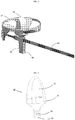
- the present invention relates to a toy comprising a rotor (20) as illustrated in figure 1 .
- the toy comprises a first toy building element (40) that comprises a launch device.
- the rotor (20) comprising a capsule (30) can be arranged on the first toy building element (40) and may subsequently be caused to rotate via an actuator means (50) that transmits a momentum to the rotor that makes the rotor rotate and fly off the launch device.
- the rotor has the shape of a rotor blade with inclining rotor blades whereby the rotor can, by rotation, take off from the launch device.
- Figure 2 shows the centrally positioned capsule (30) comprising a first capsule part (31) and a second capsule part (32).
- the first capsule part (31) comprises an actuator mechanism (33) that is illustrated as a toothed wheel (34).
- the capsule comprises means that are capable of engaging with a locking mechanism on the rotor part, whereby capsule and rotor can be locked to each other.
- a locking mechanism on the rotor part whereby capsule and rotor can be locked to each other.
- the capsule and the rotor may be constituted by one unit which cannot be taken apart.
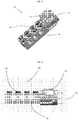
- Figure 3 shows the toy building element (40) with launch device (41) and a through-going slit (42).
- the launch device (41) is configured such that it is capable of completely or partially receiving the actuator mechanism (33).
- the slit opening (42) is located such that it extends partially through the launch device (41), whereby, when the actuator means (50) is caused to extend through the slit opening (42), the actuator means (50) may be allowed to access and engage with the actuator mechanism (33) when it is positioned in the launch device (41).
- the first toy building element comprises at least two different types of coupling means, such as coupling studs and complementary coupling means.
- the first toy building element comprises a third type of coupling means (44) in the form of through-going cylindrical holes that have a circular cross-section. This type of coupling means may receive a complementarily configured pin.
- the expanse of the through-going slit opening (42) is perpendicular to the expanse of the first and second types of coupling means whereby the direction of the tractive force from the actuator means (50) will take place at right angles to the coupling direction of the coupling means.
- the launch device (41) is configured such that it is capable of completely or partially receiving the actuator mechanism (33), whereby the actuator means (50) can be caused to extend through the through-going slit (42) and thereby transfer a momentum from the actuator means (50) to the actuator mechanism (33) thereby enabling the rotor (20) to be launched from the launch device (41).
- the launch device (41) is positioned at the one extremity of the first toy building element and is configured as a cylindrically shaped cavity, and wherein the cylindrically shaped cavity is positioned coaxially to the axis of rotation of the rotor.
- the one or more coupling means is/are positioned at the second extremity of the first toy building element.
- the first toy building element is illustrated with two different types of coupling means, viz coupling studs (43) and through-going cylindrical holes (44).
- Figure 4 shows the toy building element (40) seen from the side.
- the toy building element (40) has a launch device (41) and a through-going slit (42).
- the slit opening (42) is located such that it extends partially through the launch device (41), whereby the actuator means is enabled to engage with the actuator mechanism (33) and thereby transmit a tractive force from the actuator means (50) to a rotation force via the actuator mechanism (33) to the rotor (20) thereby enabling the rotor (20) to be launched from the launch device (41).
- Both the first type of coupling means and the second type of coupling means (not shown in the figures) that are configured complementarily to the first type of coupling means are positioned in lattice points in a first regular lattice plan.
- the third type of coupling means is positioned in lattice points in a second lattice plan at right angles to the first lattice plan.
- the third type of coupling means is located such that the centre axis of the third type of coupling means extends through the axis of rotation of the rotor.
- Figure 5 shows the toy building element (40) seen from above.
- the launch device (41) which is likewise seen from above, is configured as a cylindrical cavity illustrated with a circular cross-section.
- the through-going slit (42) is illustrated with two dotted lines, which clarifies that an actuator means (50) that is inserted into the through-going slit (42) is capable of engaging with an actuator mechanism that is located in the launch device.
Landscapes
- Toys (AREA)
Description
- The present invention relates to a toy comprising a rotor, an actuator mechanism, and a launch device, wherein the rotor comprises an actuator mechanism, and wherein the toy comprises a launch device in the form of a cavity, wherein the cavity is configured for receiving the actuator mechanism, and wherein the actuator means can be inserted into a through-going slit opening to cooperate with the actuator mechanism to the effect that a momentum can be transferred from the actuator means to the rotor, whereby the rotor can be rotated and launched from the launch device.
- Many variations of toys with flywheels and launch device are already available.
- Those types of toy typically comprise a flywheel and a launch pad, wherein the launch pad has rotation-actuating means in the form of eg a cord pull, a toothed draw bar, or an electric motor. When the flywheel is located in the launch pad, the tractive force from the cord pull or the toothed bar is transferred to a rotation force which makes the flywheel rotate, and when the rotation force becomes sufficiently strong, the flywheel takes off from the launch pad.
-
US 2014/0239591 discloses a system having a launch mechanism with an energy generation capability and a capability to launch toy entities such as surface based entities and flying entities.US patent No. 4781642 describes a toy comprising a launcher and a rotating blade. The rotating blade has a plurality of radially extending, generally horizontal blades that are adapted to rotate by means of an electric motor that is mounted within a handheld launcher. The blade has a central cockpit in which a figure device is located. - However, in many cases it is desirable to increase the options for variation.
- It is the object of the invention to provide a toy comprising a rotor, an actuator mechanism, and a launch device that create increased options for variation and are safer in use.
- This is accomplished in that the toy comprises at least two toy building elements, of which the one toy building element comprises the launch device, and wherein the toy building element is provided with one or more of first types of coupling means, and the second toy building element is provided with one or more of second types of coupling means that are geometrically configured complementarily relative to the first type of coupling means, whereby the first and second types of coupling means can be interconnected to form a spatial structure comprising the launch device.
- Hereby it is accomplished that an individual grip for the toy building element can be built, wherein the toy building elements are detachably interconnected. Moreover, the user can subsequently deconstruct and reuse the toy building elements to build new, spatial structures.
- The term "rotor" is to be understood as a device which is configured such that the rotor creates, by rotation, a lift, thereby enabling it to lift itself off the launch device; it may eg be a rotor blade with inclining rotor blades.
- According to an embodiment of the invention, one or more toy building elements comprise(s) at least two different types of coupling means, such as coupling studs and complementary coupling means. Hereby the variation options for play are increased.
- According to one embodiment, the launch device is positioned at the one extremity of the first toy building element.
- Hereby space is accomplished around the launch device, and thereby the risk is minimized that the user's fingers are caught by the rotor.
- According to an embodiment, the launch device is configured as a cylindrically shaped cavity, and wherein the cylindrically shaped cavity is positioned coaxially with the axis of rotation of the rotor.
- According to an embodiment, the one or more coupling means is/are positioned at the second extremity of the first toy building element.
- Thereby it is accomplished that a spatial structure can be built around the first toy building element with small risk of being caught by the rotor blades.
- According to an embodiment, the first and second types of the coupling means are positioned in lattice points in a first rectangular lattice plan.
- By a construction of such spatial structure, the coupling means will form a pattern. The regular lattice may be a two-dimensional lattice or a three-dimensional lattice, wherein their mutual positions and distances between the coupling means follow a geometrical pattern; and wherein the lattice may be a quadrangular, cubic lattice or rectangular lattice.
- According to an embodiment, the expanse of the through-going slit opening is perpendicular to the expanse of the first and second types of coupling means whereby the direction of the tractive force from the actuator means will take place at right angles to the coupling direction of the coupling means.
- According to an embodiment, a first toy building element comprises at least three different types of coupling means, such as coupling studs, complementary coupling means and through-going cylindrical holes.
- Hereby a wider range of variation options is accomplished for forming spatial structures that are capable of resisting the tractive force exerted by the actuator means when it actuates the rotor.
- According to one embodiment, the third type of coupling means on the first toy building element is positioned in a second, regular lattice plan which is perpendicular to the first lattice plan, and wherein the third type of coupling means is arranged such that the centre axis of the third type of coupling means extends through the axis of rotation of the rotor, whereby twisting action in the structure is minimized when the rotor is actuated.
- According to an embodiment, the first toy building element comprises a total of eight of the first type of coupling means, preferably in a lattice pattern of 2 by four coupling means.
- Hereby the first toy building element has a size and an expanse and an interconnection force when it is interconnected to a structure of several toy building elements that may reduce the risk of separation due to tractive forces and twisting actions in the structure of several toy building elements upon actuation of the rotor. Owing to the expanse of the first toy building element, it will also be possible to use the first toy building element as a handle when the rotor is launched.
- An embodiment of the invention will now be explained in further detail with reference to the drawing, wherein
-
Figure 1 illustrates a toy according to the invention, in a perspective view; -
Figure 2 illustrates a capsule with actuator mechanism; -
Figure 3 illustrates, in a perspective view, a toy building element; -
Figure 4 illustrates the toy building element, seen from the side; -
Figure 5 illustrates the toy building element, seen from above. - The present invention relates to a toy comprising a rotor (20) as illustrated in
figure 1 . - The toy comprises a first toy building element (40) that comprises a launch device. The rotor (20) comprising a capsule (30) can be arranged on the first toy building element (40) and may subsequently be caused to rotate via an actuator means (50) that transmits a momentum to the rotor that makes the rotor rotate and fly off the launch device.
- In the embodiment shown, the rotor has the shape of a rotor blade with inclining rotor blades whereby the rotor can, by rotation, take off from the launch device.
-
Figure 2 shows the centrally positioned capsule (30) comprising a first capsule part (31) and a second capsule part (32). - The first capsule part (31) comprises an actuator mechanism (33) that is illustrated as a toothed wheel (34).
- In the shown embodiment, the capsule comprises means that are capable of engaging with a locking mechanism on the rotor part, whereby capsule and rotor can be locked to each other. This can be done in different ways and, in general, in some embodiments, the capsule and the rotor may be constituted by one unit which cannot be taken apart.
-
Figure 3 shows the toy building element (40) with launch device (41) and a through-going slit (42). The launch device (41) is configured such that it is capable of completely or partially receiving the actuator mechanism (33). - The slit opening (42) is located such that it extends partially through the launch device (41), whereby, when the actuator means (50) is caused to extend through the slit opening (42), the actuator means (50) may be allowed to access and engage with the actuator mechanism (33) when it is positioned in the launch device (41).
- The first toy building element comprises at least two different types of coupling means, such as coupling studs and complementary coupling means. In the illustrated example, the first toy building element comprises a third type of coupling means (44) in the form of through-going cylindrical holes that have a circular cross-section. This type of coupling means may receive a complementarily configured pin.
- The expanse of the through-going slit opening (42) is perpendicular to the expanse of the first and second types of coupling means whereby the direction of the tractive force from the actuator means (50) will take place at right angles to the coupling direction of the coupling means.
- The launch device (41) is configured such that it is capable of completely or partially receiving the actuator mechanism (33), whereby the actuator means (50) can be caused to extend through the through-going slit (42) and thereby transfer a momentum from the actuator means (50) to the actuator mechanism (33) thereby enabling the rotor (20) to be launched from the launch device (41).
- The launch device (41) is positioned at the one extremity of the first toy building element and is configured as a cylindrically shaped cavity, and wherein the cylindrically shaped cavity is positioned coaxially to the axis of rotation of the rotor. The one or more coupling means is/are positioned at the second extremity of the first toy building element.
- The first toy building element is illustrated with two different types of coupling means, viz coupling studs (43) and through-going cylindrical holes (44).
-
Figure 4 shows the toy building element (40) seen from the side. The toy building element (40) has a launch device (41) and a through-going slit (42). - The slit opening (42) is located such that it extends partially through the launch device (41), whereby the actuator means is enabled to engage with the actuator mechanism (33) and thereby transmit a tractive force from the actuator means (50) to a rotation force via the actuator mechanism (33) to the rotor (20) thereby enabling the rotor (20) to be launched from the launch device (41).
- Both the first type of coupling means and the second type of coupling means (not shown in the figures) that are configured complementarily to the first type of coupling means are positioned in lattice points in a first regular lattice plan. The third type of coupling means is positioned in lattice points in a second lattice plan at right angles to the first lattice plan.
- The third type of coupling means is located such that the centre axis of the third type of coupling means extends through the axis of rotation of the rotor.
-
Figure 5 shows the toy building element (40) seen from above. The launch device (41), which is likewise seen from above, is configured as a cylindrical cavity illustrated with a circular cross-section. The through-going slit (42) is illustrated with two dotted lines, which clarifies that an actuator means (50) that is inserted into the through-going slit (42) is capable of engaging with an actuator mechanism that is located in the launch device.
Claims (10)
- A toy comprising a rotor (20), an actuator mechanism (33), and a launch device (41), wherein the rotor comprises the actuator mechanism (33), and wherein the toy comprises the launch device (41) in the form of a cavity, wherein the cavity is configured for receiving the actuator mechanism (33), and wherein an actuator means (50) can be inserted into a through-going slit opening (42) to cooperate with the actuator mechanism to the effect that a momentum can be transferred from the actuator means (50) to the rotor (20), whereby the rotor can be rotated and launched from the launch device, characterised in that the toy comprises at least a first toy building element and a second toy building element, of which the first toy building element (40) comprises the launch device (41), and wherein the first toy building element (40) is provided with one or more of first types of coupling means (43), and the second toy building element is provided with one or more of second types of coupling means that are geometrically configured complementarily relative to the first type of coupling means, whereby the first and second types of coupling means can be interconnected to form a spatial structure comprising the launch device (41).
- A toy according to claim 1, wherein one or more of the toy building elements comprise(s) at least two different types of coupling means, such as both coupling studs and complementary coupling means.
- A toy according to one or more of the preceding claims, wherein the launch device (41) is positioned at the one extremity of the first toy building element.
- A toy according to one or more of the preceding claims, wherein the launch device (41) is configured as a cylindrically shaped cavity, and wherein the cylindrically shaped cavity is positioned coaxially with the axis of rotation of the rotor.
- A toy according to one or more of the preceding claims, wherein the one or more coupling means is/are positioned at the second extremity of the first toy building element.
- A toy according to one or more of the preceding claims, wherein the first and second types of the coupling means are positioned in lattice points in a first regular lattice plan.
- A toy according to one or more of the preceding claims, wherein the expanse of the through-going slit opening (42) is perpendicular to the expanse of the first and second types of coupling means whereby the direction of the tractive force from the actuator means (50) will take place at right angles to the coupling direction of the coupling means.
- A toy according to one or more of the preceding claims, wherein the first toy building element (40) comprises at least three different types of coupling means, such as coupling studs, complementary coupling means and through-going cylindrical holes.
- A toy according to the preceding claim, wherein the third type of coupling means on the first toy building element is positioned in lattice points in a second, regular lattice plan which is perpendicular to the first lattice plan, and wherein the third type of coupling means is arranged such that the centre axis of the third type of coupling means extends through the axis of rotation of the rotor, whereby twisting action in a structure is minimized when the rotor is actuated.
- A toy according to one or more of the preceding claims, wherein the first toy building element comprises a total of eight of the first type of coupling means, preferably in a lattice pattern of two by four coupling means.
Applications Claiming Priority (2)
| Application Number | Priority Date | Filing Date | Title |
|---|---|---|---|
| DKPA201570031 | 2015-01-21 | ||
| PCT/DK2016/050013 WO2016116108A1 (en) | 2015-01-21 | 2016-01-18 | A toy comprising a rotor, an activation mechanism and a launching device |
Publications (2)
| Publication Number | Publication Date |
|---|---|
| EP3247478A1 EP3247478A1 (en) | 2017-11-29 |
| EP3247478B1 true EP3247478B1 (en) | 2019-06-26 |
Family
ID=55398144
Family Applications (1)
| Application Number | Title | Priority Date | Filing Date |
|---|---|---|---|
| EP16705019.4A Active EP3247478B1 (en) | 2015-01-21 | 2016-01-18 | A toy comprising a rotor, an activation mechanism and a launching device |
Country Status (5)
| Country | Link |
|---|---|
| US (1) | US10080976B2 (en) |
| EP (1) | EP3247478B1 (en) |
| CN (1) | CN107405528B (en) |
| DK (1) | DK3247478T3 (en) |
| WO (1) | WO2016116108A1 (en) |
Families Citing this family (7)
| Publication number | Priority date | Publication date | Assignee | Title |
|---|---|---|---|---|
| USD844394S1 (en) | 2018-03-29 | 2019-04-02 | Kraft Foods Group Brands Llc | Mold |
| US10894342B2 (en) | 2018-03-29 | 2021-01-19 | Kraft Foods Group Brands Llc | System and method for molding comestible building blocks |
| JP7514659B2 (en) * | 2020-05-07 | 2024-07-11 | 秀夫 樋口 | Rotating projectile launcher |
| US20260022920A1 (en) * | 2024-09-30 | 2026-01-22 | Aob Products Company | Shooting target launcher |
| USD1115921S1 (en) | 2025-01-22 | 2026-03-03 | Aob Products Company | Target |
| USD1125374S1 (en) | 2025-01-22 | 2026-05-05 | Aob Products Company | Target |
| USD1115920S1 (en) | 2025-01-22 | 2026-03-03 | Aob Products Company | Target |
Family Cites Families (36)
| Publication number | Priority date | Publication date | Assignee | Title |
|---|---|---|---|---|
| US951686A (en) * | 1909-04-24 | 1910-03-08 | William Wesley Katterjohn | Flying toy. |
| US2051151A (en) * | 1935-07-16 | 1936-08-18 | Northill Co Inc | Aeronautical toy |
| US2561554A (en) * | 1948-07-14 | 1951-07-24 | Barist Michael | Device for spinning toys |
| US2938300A (en) * | 1958-07-17 | 1960-05-31 | Alfred R Newbert | Rotor spinning device |
| US3246424A (en) * | 1963-04-11 | 1966-04-19 | Joseph E Gregory | Spinning toy launcher |
| US3570467A (en) * | 1967-06-16 | 1971-03-16 | Woodstream Corp | Bird launcher |
| US3605328A (en) * | 1969-12-10 | 1971-09-20 | Mattel Inc | Rotor launching toy |
| US3704540A (en) * | 1970-08-24 | 1972-12-05 | Olympic Overseas Inc | Helicopter with rotor having metal ring for flywheel effect |
| US3701216A (en) * | 1971-12-22 | 1972-10-31 | California R & D Center | Wheel apparatus and rack and pinion launcher enabling repeated strokes and having automatic ejector |
| US4030238A (en) * | 1976-05-04 | 1977-06-21 | Lakin Willis M | Rotating toys, particularly flying toys |
| ES461493A1 (en) * | 1977-08-08 | 1979-01-01 | Mateo Otal Plo | flying toy |
| NL8503134A (en) * | 1985-11-14 | 1987-06-01 | Cornelia Petronella Maria West | BUILDING ELEMENT AND CONNECTORS FOR CONNECTING BUILT-UP ELEMENTS. |
| US4781642A (en) * | 1987-07-29 | 1988-11-01 | Victor Stanzel | Rotary flying toy |
| US4959035A (en) * | 1988-03-10 | 1990-09-25 | Sega Enterprises, Ltd. | Miniature storage container for a manually propelled toy member |
| JPH0691062A (en) | 1992-09-16 | 1994-04-05 | Sankyo Seiki Mfg Co Ltd | Block unit for block toy |
| US5474482A (en) * | 1994-05-09 | 1995-12-12 | Davidson; Frankie G. | Aerodynamic rotor with chemiluminescent light source holder |
| US5525086A (en) * | 1995-03-13 | 1996-06-11 | Gentile; John | Launchable figurine device |
| JP3827253B2 (en) | 1996-10-09 | 2006-09-27 | 株式会社システムワット | Assembly block and assembly toy system |
| ES1041052Y (en) | 1998-08-28 | 1999-11-01 | Nestle Sa | PERFECTED ICE CREAM. |
| US20020098768A1 (en) * | 2001-01-19 | 2002-07-25 | Kuo Yin Jyh | Audio and video effect flight toy |
| JP3944392B2 (en) | 2001-12-27 | 2007-07-11 | 株式会社センテクリエイションズ | Rotating toy |
| JP2004065593A (en) | 2002-08-06 | 2004-03-04 | Takara Co Ltd | Propeller flying toy device |
| US6921313B2 (en) * | 2003-02-14 | 2005-07-26 | Derrick Yu | Illuminated flying toy |
| US20060148373A1 (en) * | 2004-08-25 | 2006-07-06 | Jakks Pacific, Inc. | Integrated carrying case and toy object launcher |
| US7500898B2 (en) * | 2004-08-25 | 2009-03-10 | Jakks Pacific, Incorporation | Toy for rotating and launching an object |
| US20070117492A1 (en) * | 2005-02-15 | 2007-05-24 | Sze Chau K | Flying toy for propeller launching with liquid dispersing parts |
| WO2006088465A1 (en) * | 2005-02-15 | 2006-08-24 | Chau King Sze | Flying toy for propeller launching |
| US7727047B2 (en) * | 2005-05-04 | 2010-06-01 | Julian Edward Lopez | Toy and method of toy operation |
| US7950976B2 (en) * | 2005-07-14 | 2011-05-31 | Jakks Pacific, Inc. | Toy for rotating and launching an object |
| CN2822723Y (en) * | 2005-08-12 | 2006-10-04 | 高勇 | Flying wheel toy |
| CN201046340Y (en) * | 2007-02-16 | 2008-04-16 | 蔡东青 | Top projector with high security |
| TW201034733A (en) * | 2009-03-26 | 2010-10-01 | Genius Toy Taiwan Co Ltd | Injection building block unit |
| JP3164823U (en) * | 2010-10-06 | 2010-12-16 | 株式会社タカラトミー | Top toy launcher |
| EP2838628B1 (en) * | 2012-04-18 | 2017-06-14 | Lego A/S | A toy building set |
| CN102743882A (en) | 2012-07-30 | 2012-10-24 | 无锡同春新能源科技有限公司 | Lighting bamboo dragonfly using solar photovoltaic generation as supply power |
| US9610515B2 (en) * | 2013-02-25 | 2017-04-04 | Rehco, Llc | System to launch a toy entity and methods of play |
-
2016
- 2016-01-18 WO PCT/DK2016/050013 patent/WO2016116108A1/en not_active Ceased
- 2016-01-18 EP EP16705019.4A patent/EP3247478B1/en active Active
- 2016-01-18 DK DK16705019.4T patent/DK3247478T3/en active
- 2016-01-18 CN CN201680016685.6A patent/CN107405528B/en active Active
- 2016-01-18 US US15/544,124 patent/US10080976B2/en active Active
Non-Patent Citations (1)
| Title |
|---|
| None * |
Also Published As
| Publication number | Publication date |
|---|---|
| US20170361238A1 (en) | 2017-12-21 |
| CN107405528B (en) | 2020-05-19 |
| CN107405528A (en) | 2017-11-28 |
| WO2016116108A1 (en) | 2016-07-28 |
| US10080976B2 (en) | 2018-09-25 |
| DK3247478T3 (en) | 2019-09-23 |
| EP3247478A1 (en) | 2017-11-29 |
Similar Documents
| Publication | Publication Date | Title |
|---|---|---|
| US10080976B2 (en) | Toy comprising a rotor, an activation mechanism and a launching device | |
| EP2692401B1 (en) | Detachable propeller for flying toys | |
| CN201895770U (en) | Locking and unlocking mechanism for aircraft airfoil | |
| US9499263B2 (en) | Multi-rotor aircraft | |
| US20100044499A1 (en) | Six rotor helicopter | |
| US10137381B2 (en) | Toy comprising a rotor | |
| US20160009381A1 (en) | System for fast fixing an accessory to a drone body | |
| EP2759323B1 (en) | Flying toy figurine | |
| JP5812849B2 (en) | Small drone | |
| WO2011035525A1 (en) | Propeller connecting piece for electric model airplane | |
| JP2015110413A (en) | Rotation blade pilotless aircraft equipped with gearless drive part and quickly attachable propeller | |
| KR20170018671A (en) | Hybrid system of drone | |
| US20120258645A1 (en) | Shooting device for RC helicopter | |
| IT201900010008A1 (en) | AIRCRAFT, IN PARTICULAR AUTONOMOUS DRONE OR AIRCRAFT FOR PERSONAL AERIAL MOBILITY, WITH HIGH EFFICIENCY ROTORS | |
| US20170101177A1 (en) | Chain-Connected Micro-Areal Vehicles | |
| KR20070108327A (en) | Flying toy to launch the propeller | |
| CN105366032B (en) | Unmanned plane with foldable assembly | |
| JP3239605U (en) | unmanned aerial vehicle | |
| US20130130586A1 (en) | Tether assembly for a radio frequency controlled aircraft | |
| US8864545B2 (en) | Radio frequency controlled aircraft | |
| WO2017040004A1 (en) | Method, apparatus, and system for toy building block(s) with chain reaction trigger | |
| KR101495863B1 (en) | Gliding robot system with single actuator | |
| US7727047B2 (en) | Toy and method of toy operation | |
| CN207689917U (en) | A kind of eight rotor omnidirectional aircraft of non-planar | |
| CN121588478A (en) | Toy spinning tops and toy systems containing toy spinning tops and toy figurines |
Legal Events
| Date | Code | Title | Description |
|---|---|---|---|
| STAA | Information on the status of an ep patent application or granted ep patent |
Free format text: STATUS: THE INTERNATIONAL PUBLICATION HAS BEEN MADE |
|
| PUAI | Public reference made under article 153(3) epc to a published international application that has entered the european phase |
Free format text: ORIGINAL CODE: 0009012 |
|
| STAA | Information on the status of an ep patent application or granted ep patent |
Free format text: STATUS: REQUEST FOR EXAMINATION WAS MADE |
|
| 17P | Request for examination filed |
Effective date: 20170815 |
|
| AK | Designated contracting states |
Kind code of ref document: A1 Designated state(s): AL AT BE BG CH CY CZ DE DK EE ES FI FR GB GR HR HU IE IS IT LI LT LU LV MC MK MT NL NO PL PT RO RS SE SI SK SM TR |
|
| AX | Request for extension of the european patent |
Extension state: BA ME |
|
| DAV | Request for validation of the european patent (deleted) | ||
| DAX | Request for extension of the european patent (deleted) | ||
| RIC1 | Information provided on ipc code assigned before grant |
Ipc: A63H 27/00 20060101ALI20181207BHEP Ipc: A63H 33/08 20060101ALI20181207BHEP Ipc: A63H 27/14 20060101AFI20181207BHEP Ipc: A63H 1/04 20060101ALI20181207BHEP |
|
| GRAP | Despatch of communication of intention to grant a patent |
Free format text: ORIGINAL CODE: EPIDOSNIGR1 |
|
| STAA | Information on the status of an ep patent application or granted ep patent |
Free format text: STATUS: GRANT OF PATENT IS INTENDED |
|
| INTG | Intention to grant announced |
Effective date: 20190118 |
|
| GRAS | Grant fee paid |
Free format text: ORIGINAL CODE: EPIDOSNIGR3 |
|
| GRAA | (expected) grant |
Free format text: ORIGINAL CODE: 0009210 |
|
| STAA | Information on the status of an ep patent application or granted ep patent |
Free format text: STATUS: THE PATENT HAS BEEN GRANTED |
|
| AK | Designated contracting states |
Kind code of ref document: B1 Designated state(s): AL AT BE BG CH CY CZ DE DK EE ES FI FR GB GR HR HU IE IS IT LI LT LU LV MC MK MT NL NO PL PT RO RS SE SI SK SM TR |
|
| REG | Reference to a national code |
Ref country code: GB Ref legal event code: FG4D |
|
| REG | Reference to a national code |
Ref country code: CH Ref legal event code: EP |
|
| REG | Reference to a national code |
Ref country code: DE Ref legal event code: R096 Ref document number: 602016015894 Country of ref document: DE |
|
| REG | Reference to a national code |
Ref country code: AT Ref legal event code: REF Ref document number: 1147639 Country of ref document: AT Kind code of ref document: T Effective date: 20190715 |
|
| REG | Reference to a national code |
Ref country code: IE Ref legal event code: FG4D |
|
| REG | Reference to a national code |
Ref country code: DK Ref legal event code: T3 Effective date: 20190919 |
|
| REG | Reference to a national code |
Ref country code: NL Ref legal event code: MP Effective date: 20190626 |
|
| PG25 | Lapsed in a contracting state [announced via postgrant information from national office to epo] |
Ref country code: NO Free format text: LAPSE BECAUSE OF FAILURE TO SUBMIT A TRANSLATION OF THE DESCRIPTION OR TO PAY THE FEE WITHIN THE PRESCRIBED TIME-LIMIT Effective date: 20190926 Ref country code: FI Free format text: LAPSE BECAUSE OF FAILURE TO SUBMIT A TRANSLATION OF THE DESCRIPTION OR TO PAY THE FEE WITHIN THE PRESCRIBED TIME-LIMIT Effective date: 20190626 Ref country code: LT Free format text: LAPSE BECAUSE OF FAILURE TO SUBMIT A TRANSLATION OF THE DESCRIPTION OR TO PAY THE FEE WITHIN THE PRESCRIBED TIME-LIMIT Effective date: 20190626 Ref country code: HR Free format text: LAPSE BECAUSE OF FAILURE TO SUBMIT A TRANSLATION OF THE DESCRIPTION OR TO PAY THE FEE WITHIN THE PRESCRIBED TIME-LIMIT Effective date: 20190626 Ref country code: SE Free format text: LAPSE BECAUSE OF FAILURE TO SUBMIT A TRANSLATION OF THE DESCRIPTION OR TO PAY THE FEE WITHIN THE PRESCRIBED TIME-LIMIT Effective date: 20190626 Ref country code: AL Free format text: LAPSE BECAUSE OF FAILURE TO SUBMIT A TRANSLATION OF THE DESCRIPTION OR TO PAY THE FEE WITHIN THE PRESCRIBED TIME-LIMIT Effective date: 20190626 |
|
| REG | Reference to a national code |
Ref country code: LT Ref legal event code: MG4D |
|
| PG25 | Lapsed in a contracting state [announced via postgrant information from national office to epo] |
Ref country code: LV Free format text: LAPSE BECAUSE OF FAILURE TO SUBMIT A TRANSLATION OF THE DESCRIPTION OR TO PAY THE FEE WITHIN THE PRESCRIBED TIME-LIMIT Effective date: 20190626 Ref country code: BG Free format text: LAPSE BECAUSE OF FAILURE TO SUBMIT A TRANSLATION OF THE DESCRIPTION OR TO PAY THE FEE WITHIN THE PRESCRIBED TIME-LIMIT Effective date: 20190926 Ref country code: RS Free format text: LAPSE BECAUSE OF FAILURE TO SUBMIT A TRANSLATION OF THE DESCRIPTION OR TO PAY THE FEE WITHIN THE PRESCRIBED TIME-LIMIT Effective date: 20190626 Ref country code: GR Free format text: LAPSE BECAUSE OF FAILURE TO SUBMIT A TRANSLATION OF THE DESCRIPTION OR TO PAY THE FEE WITHIN THE PRESCRIBED TIME-LIMIT Effective date: 20190927 |
|
| REG | Reference to a national code |
Ref country code: AT Ref legal event code: MK05 Ref document number: 1147639 Country of ref document: AT Kind code of ref document: T Effective date: 20190626 |
|
| PG25 | Lapsed in a contracting state [announced via postgrant information from national office to epo] |
Ref country code: CZ Free format text: LAPSE BECAUSE OF FAILURE TO SUBMIT A TRANSLATION OF THE DESCRIPTION OR TO PAY THE FEE WITHIN THE PRESCRIBED TIME-LIMIT Effective date: 20190626 Ref country code: PT Free format text: LAPSE BECAUSE OF FAILURE TO SUBMIT A TRANSLATION OF THE DESCRIPTION OR TO PAY THE FEE WITHIN THE PRESCRIBED TIME-LIMIT Effective date: 20191028 Ref country code: SK Free format text: LAPSE BECAUSE OF FAILURE TO SUBMIT A TRANSLATION OF THE DESCRIPTION OR TO PAY THE FEE WITHIN THE PRESCRIBED TIME-LIMIT Effective date: 20190626 Ref country code: AT Free format text: LAPSE BECAUSE OF FAILURE TO SUBMIT A TRANSLATION OF THE DESCRIPTION OR TO PAY THE FEE WITHIN THE PRESCRIBED TIME-LIMIT Effective date: 20190626 Ref country code: NL Free format text: LAPSE BECAUSE OF FAILURE TO SUBMIT A TRANSLATION OF THE DESCRIPTION OR TO PAY THE FEE WITHIN THE PRESCRIBED TIME-LIMIT Effective date: 20190626 Ref country code: EE Free format text: LAPSE BECAUSE OF FAILURE TO SUBMIT A TRANSLATION OF THE DESCRIPTION OR TO PAY THE FEE WITHIN THE PRESCRIBED TIME-LIMIT Effective date: 20190626 Ref country code: RO Free format text: LAPSE BECAUSE OF FAILURE TO SUBMIT A TRANSLATION OF THE DESCRIPTION OR TO PAY THE FEE WITHIN THE PRESCRIBED TIME-LIMIT Effective date: 20190626 |
|
| PG25 | Lapsed in a contracting state [announced via postgrant information from national office to epo] |
Ref country code: IT Free format text: LAPSE BECAUSE OF FAILURE TO SUBMIT A TRANSLATION OF THE DESCRIPTION OR TO PAY THE FEE WITHIN THE PRESCRIBED TIME-LIMIT Effective date: 20190626 Ref country code: ES Free format text: LAPSE BECAUSE OF FAILURE TO SUBMIT A TRANSLATION OF THE DESCRIPTION OR TO PAY THE FEE WITHIN THE PRESCRIBED TIME-LIMIT Effective date: 20190626 Ref country code: SM Free format text: LAPSE BECAUSE OF FAILURE TO SUBMIT A TRANSLATION OF THE DESCRIPTION OR TO PAY THE FEE WITHIN THE PRESCRIBED TIME-LIMIT Effective date: 20190626 Ref country code: IS Free format text: LAPSE BECAUSE OF FAILURE TO SUBMIT A TRANSLATION OF THE DESCRIPTION OR TO PAY THE FEE WITHIN THE PRESCRIBED TIME-LIMIT Effective date: 20191026 |
|
| PG25 | Lapsed in a contracting state [announced via postgrant information from national office to epo] |
Ref country code: TR Free format text: LAPSE BECAUSE OF FAILURE TO SUBMIT A TRANSLATION OF THE DESCRIPTION OR TO PAY THE FEE WITHIN THE PRESCRIBED TIME-LIMIT Effective date: 20190626 |
|
| PG25 | Lapsed in a contracting state [announced via postgrant information from national office to epo] |
Ref country code: PL Free format text: LAPSE BECAUSE OF FAILURE TO SUBMIT A TRANSLATION OF THE DESCRIPTION OR TO PAY THE FEE WITHIN THE PRESCRIBED TIME-LIMIT Effective date: 20190626 |
|
| PG25 | Lapsed in a contracting state [announced via postgrant information from national office to epo] |
Ref country code: IS Free format text: LAPSE BECAUSE OF FAILURE TO SUBMIT A TRANSLATION OF THE DESCRIPTION OR TO PAY THE FEE WITHIN THE PRESCRIBED TIME-LIMIT Effective date: 20200224 |
|
| REG | Reference to a national code |
Ref country code: DE Ref legal event code: R097 Ref document number: 602016015894 Country of ref document: DE |
|
| PLBE | No opposition filed within time limit |
Free format text: ORIGINAL CODE: 0009261 |
|
| STAA | Information on the status of an ep patent application or granted ep patent |
Free format text: STATUS: NO OPPOSITION FILED WITHIN TIME LIMIT |
|
| PG2D | Information on lapse in contracting state deleted |
Ref country code: IS |
|
| 26N | No opposition filed |
Effective date: 20200603 |
|
| PG25 | Lapsed in a contracting state [announced via postgrant information from national office to epo] |
Ref country code: MC Free format text: LAPSE BECAUSE OF FAILURE TO SUBMIT A TRANSLATION OF THE DESCRIPTION OR TO PAY THE FEE WITHIN THE PRESCRIBED TIME-LIMIT Effective date: 20190626 Ref country code: SI Free format text: LAPSE BECAUSE OF FAILURE TO SUBMIT A TRANSLATION OF THE DESCRIPTION OR TO PAY THE FEE WITHIN THE PRESCRIBED TIME-LIMIT Effective date: 20190626 |
|
| REG | Reference to a national code |
Ref country code: CH Ref legal event code: PL |
|
| REG | Reference to a national code |
Ref country code: BE Ref legal event code: MM Effective date: 20200131 |
|
| PG25 | Lapsed in a contracting state [announced via postgrant information from national office to epo] |
Ref country code: FR Free format text: LAPSE BECAUSE OF NON-PAYMENT OF DUE FEES Effective date: 20200131 Ref country code: LU Free format text: LAPSE BECAUSE OF NON-PAYMENT OF DUE FEES Effective date: 20200118 |
|
| PG25 | Lapsed in a contracting state [announced via postgrant information from national office to epo] |
Ref country code: BE Free format text: LAPSE BECAUSE OF NON-PAYMENT OF DUE FEES Effective date: 20200131 Ref country code: LI Free format text: LAPSE BECAUSE OF NON-PAYMENT OF DUE FEES Effective date: 20200131 Ref country code: CH Free format text: LAPSE BECAUSE OF NON-PAYMENT OF DUE FEES Effective date: 20200131 |
|
| PG25 | Lapsed in a contracting state [announced via postgrant information from national office to epo] |
Ref country code: IE Free format text: LAPSE BECAUSE OF NON-PAYMENT OF DUE FEES Effective date: 20200118 |
|
| PG25 | Lapsed in a contracting state [announced via postgrant information from national office to epo] |
Ref country code: MT Free format text: LAPSE BECAUSE OF FAILURE TO SUBMIT A TRANSLATION OF THE DESCRIPTION OR TO PAY THE FEE WITHIN THE PRESCRIBED TIME-LIMIT Effective date: 20190626 Ref country code: CY Free format text: LAPSE BECAUSE OF FAILURE TO SUBMIT A TRANSLATION OF THE DESCRIPTION OR TO PAY THE FEE WITHIN THE PRESCRIBED TIME-LIMIT Effective date: 20190626 |
|
| PG25 | Lapsed in a contracting state [announced via postgrant information from national office to epo] |
Ref country code: MK Free format text: LAPSE BECAUSE OF FAILURE TO SUBMIT A TRANSLATION OF THE DESCRIPTION OR TO PAY THE FEE WITHIN THE PRESCRIBED TIME-LIMIT Effective date: 20190626 |
|
| P01 | Opt-out of the competence of the unified patent court (upc) registered |
Effective date: 20230512 |
|
| PGFP | Annual fee paid to national office [announced via postgrant information from national office to epo] |
Ref country code: GB Payment date: 20260123 Year of fee payment: 11 |
|
| PGFP | Annual fee paid to national office [announced via postgrant information from national office to epo] |
Ref country code: DE Payment date: 20260121 Year of fee payment: 11 Ref country code: DK Payment date: 20260126 Year of fee payment: 11 |