EP3247477B1 - A toy comprising a rotor - Google Patents
A toy comprising a rotor Download PDFInfo
- Publication number
- EP3247477B1 EP3247477B1 EP16705020.2A EP16705020A EP3247477B1 EP 3247477 B1 EP3247477 B1 EP 3247477B1 EP 16705020 A EP16705020 A EP 16705020A EP 3247477 B1 EP3247477 B1 EP 3247477B1
- Authority
- EP
- European Patent Office
- Prior art keywords
- capsule
- rotor
- toy
- locking mechanism
- actuator
- Prior art date
- Legal status (The legal status is an assumption and is not a legal conclusion. Google has not performed a legal analysis and makes no representation as to the accuracy of the status listed.)
- Active
Links
Images


Classifications
-
- A—HUMAN NECESSITIES
- A63—SPORTS; GAMES; AMUSEMENTS
- A63H—TOYS, e.g. TOPS, DOLLS, HOOPS OR BUILDING BLOCKS
- A63H27/00—Toy aircraft; Other flying toys
- A63H27/12—Helicopters ; Flying tops
-
- A—HUMAN NECESSITIES
- A23—FOODS OR FOODSTUFFS; TREATMENT THEREOF, NOT COVERED BY OTHER CLASSES
- A23G—COCOA; COCOA PRODUCTS, e.g. CHOCOLATE; SUBSTITUTES FOR COCOA OR COCOA PRODUCTS; CONFECTIONERY; CHEWING GUM; ICE-CREAM; PREPARATION THEREOF
- A23G3/00—Sweetmeats; Confectionery; Marzipan; Coated or filled products
- A23G3/34—Sweetmeats, confectionery or marzipan; Processes for the preparation thereof
- A23G3/50—Sweetmeats, confectionery or marzipan; Processes for the preparation thereof characterised by shape, structure or physical form, e.g. products with supported structure
- A23G3/56—Products with edible or inedible supports, e.g. lollipops
- A23G3/563—Products with edible or inedible supports, e.g. lollipops products with an inedible support, e.g. a stick
-
- A—HUMAN NECESSITIES
- A63—SPORTS; GAMES; AMUSEMENTS
- A63H—TOYS, e.g. TOPS, DOLLS, HOOPS OR BUILDING BLOCKS
- A63H27/00—Toy aircraft; Other flying toys
- A63H27/14—Starting or launching devices for toy aircraft; Arrangements on toy aircraft for starting or launching
Definitions
- a toy comprising a rotor and a centrally arranged capsule, wherein the capsule comprises an actuator mechanism that is configured to cooperate with a launch element and an actuator means, wherein the actuator means is configured for engaging with the actuator mechanism to transfer a momentum to the rotor, whereby the rotor can rotate and be launched from the launch element.
- Those types of toy typically comprise a rotor and a position for launching, wherein the launch pad has rotation-actuating means in the form of eg a cord pull, a toothed draw bar, or an electric motor.
- rotation-actuating means in the form of eg a cord pull, a toothed draw bar, or an electric motor.
- US patent No. 4781642 describes a toy comprising a launcher and a rotating blade.
- the rotating blade has a plurality of radially extending, generally horizontal blades that are adapted to rotate by means of an electric motor that is mounted within a handheld launcher.
- the blade has a central cockpit in which a figure device is located.
- the capsule is a separate part relative to the rotor, and that the capsule comprises at least two capsule parts whereby the two capsule parts can be opened when the rotor and the capsule are separated, and wherein rotor, capsule and the actuator mechanism are connected to each other to the effect that the momentum from the actuator means is transferred to the actuator mechanism that conveys the momentum on from the capsule to the rotor, when the at least two capsule parts are closed.
- rotor is to be understood as a device which is configured such that the rotor creates, by rotation, a lift, thereby enabling it to lift itself off the launch device; it may eg be a rotor blade with inclining rotor blades.
- the rotor comprises a centred circular through-going hole for receiving the capsule when the two capsule parts are interconnected.
- the capsule is positioned and, in a particular embodiment, is also secured flush-centre in the rotor for stable flying.
- the rotor comprises a locking mechanism, whereby the at least two capsule parts remain connected to each other and the rotor, when the rotor is launched.
- the toy is safer since the capsule is not opened unintentionally following launching, and hence that the risk is reduced that a figure contained within the capsule is ejected from the capsule.
- the first capsule part comprises the actuator mechanism
- the locking mechanism on the rotor is configured such that the locking mechanism locks the first capsule part to the rotor when the first capsule part is connected to the second capsule part whereby both capsule parts and the rotor must be interconnected via the locking mechanism before a transfer of force takes place from capsule comprising the actuator mechanism to the rotor.
- the locking mechanism is constituted by a bayonet fastening, wherein the rotor comprises one or more protrusions that are configured for engaging with the recess in the capsule whereby the bayonet fastening locks the rotor to the capsule when the two capsule parts are connected.
- the locking mechanism is positioned at a distance from the central through-going hole which is larger than the expanse of the first capsule part when the first capsule part alone is connected to the rotor to the effect that the first capsule part can rotate without the rotor.
- the locking mechanism locks the first capsule part to the rotor only when the first and second capsule parts are connected.
- the locking direction of the locking mechanism is equal to the direction of rotation of the rotor, and the locking mechanism maintains the first and the second capsule parts mutually interconnected to the effect that unintended separation of rotor and capsule is prevented when the rotor is launched.
- the capsule comprises, interiorly, coupling means.
- coupling means whereby it is accomplished that the figure can be securely coupled within the capsule.
- the at least one capsule part is configured from a transparent material.
- a figure arranged within the capsule is visible.
- the actuator means is configured with a cross-section corresponding to the cross-section of the slit opening on the launch element whereby the actuator means is capable of engaging and influencing the actuator mechanism in one direction of rotation only, whereby the direction of rotation of the rotor will, when being launched, lock the locking mechanism whereby unintended separation between the capsule and the rotor is avoided.
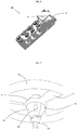
- the present invention relates, as shown in figure 1 , a toy (10) comprising a rotor (20).
- the toy (10) comprises a rotor (20) and a centrally arranged capsule (30), wherein the capsule is configured to cooperate with a launch element (40) and an actuator means (50), wherein the actuator means is configured for engaging with the actuator mechanism (33) to transfer a momentum to the rotor (20).
- the rotor (20) with closed capsule (30) is arranged on a launch element (40) and can be caused to rotate via an actuator mechanism and the actuator means (50). The rotor can rotate and be launched from the launch element (40) when the capsule is closed.
- the capsule (30) comprises at least two capsule parts (31, 32) and is a separate part relative to the rotor. When the rotor and the capsule are separated, the at least two capsule parts (31, 32) can be opened.
- the toy is configured such that a momentum from the actuator means (50) is transferred only to the actuator mechanism (33) which conveys the momentum from the capsule (30) on to the rotor (20) when the at least two capsule parts (31, 32) are interconnected.
- the rotor cannot be actuated when only the one capsule part is present.
- Figure 2 shows a first capsule part (31), and figure 3 shows a second capsule part.
- the first capsule part (31) comprises an actuator mechanism (33) which is illustrated as a toothed wheel (34). Moreover, the shown first capsule part (31) comprises an indentation (36), capsule coupling means (35) and coupling means (39) for positioning of a figure (not shown).
- the second capsule part (32), shown in figure 3 comprises complementary capsule coupling means (35) whereby the two capsule parts can be interconnected via the capsule coupling means (35).
- the second capsule part moreover comprises two cut-outs, a cut-out (37) for passage of locking mechanism (21) (shown in figure 5 ) and a second cut-out (38) for abutment of the locking mechanism (21), respectively.
- the second cut-out has a concave configuration.
- the locking mechanism (21) is illustrated as a bayonet fastening in the form of a protrusion on the rotor that can pass the two cut-outs (36, 37) on the two capsule parts, and then the protrusion can be rotated in an anti-clockwise direction for fixed position with the protrusion by abutment on the side face of the second cut-out (38) on the second capsule part (32).
- the locking mechanism thereby retains both the two capsule parts and the rotor in interconnected position.
- Figure 4 shows the two capsule parts (31, 32) interconnected to a closed capsule.
- the one capsule part (31) comprises an actuator mechanism (33) in the form of a toothed wheel (34).
- the one capsule part also comprises an indentation (36) for passage of the locking mechanism (21) illustrated as a protrusion on the rotor in figure 5 .
- the second capsule part (32) comprises a cut-out (37) for passage of the locking mechanism (21) (shown in figure 5 ) and a second cut-out (38) for abutment of the locking mechanism (21).
- Figure 5 shows the rotor with the circular periphery seen from above.
- the rotor comprises two locking mechanisms (21) in the shape of two protrusions and a centrally arranged through-going hole (22) and three swivel arms (23).
- the cut-outs (37, 38) in figure 3 are for passage of the locking mechanism (21), when the at least two capsule parts and the rotor are interconnected and securely locked to each other.
- the shown bayonet fastening is configured such that when the two capsule parts are interconnected and are conveyed partially through the centrally arranged through-going hole (22), the locking mechanism (21) in the shape of protrusions will, in turn, pass the cut-out (37) and then the capsule may be caused to rotate about the centre axis whereby the protrusion is turned and abuts on the concave cut-out (38), and thereby capsule and rotor are securely locked to each other about the axis of rotation in the same direction as the locking direction.
- the locking mechanism (21) is positioned at a distance along the centre axis from the central through-going hole (22) which is larger than the expanse of the first capsule part (31) when this first capsule part (31) only is connected to the rotor (20).
- the first capsule part (31) can rotate in the central through-going hole (22) without it being locked to the locking mechanism (21), and thereby the first capsule part can be rotated without rotating the rotor (20).
- Figure 6 shows the launch element (40) with the launch device (41) and a through-going slit (42).
- the launching position (41) is configured to completely or partially receive the actuator mechanism (33) whereby the actuator means (50), when it is introduced into the through-going slot, can engage with the actuator mechanism (33).
- the actuator mechanism (33) sits on the first capsule part (31), and the locking mechanism (21) is configured to lock the first capsule part (31) to the rotor only when the first capsule part (31) is connected to the second capsule part (22) to the effect that both capsule parts and the rotor (20) need to be interconnected via the locking mechanism (21) before a transfer of force from the capsule (30) comprising the actuator mechanism (33) to the rotor (20).
- the locking mechanism (21) is constituted by a bayonet fastening in the form of a protrusion. That protrusion is positioned at a distance from the centrally located through-going hole (22). The protrusion will be arranged over the first capsule part when it is mounted on its own in the central hole in the rotor and will thereby not lock the first capsule part to the rotor, and hence the first capsule part will be poor at transferring the rotation force to the rotor if it is attempted to insert only the rotor and the first capsule part in the launch element (40).
- the capsule may be completely or partially made of a transparent material. Thereby it is possible to see a figure placed within the capsule.
- Figure 7 shows an alternative construction of the two capsule parts (31, 32) and the rotor (20).
- the capsule is divided in the same plane as the axis of rotation and can be kept together by the locking mechanism (21) of the rotor which is, in this case, configured as a cylindrical band that squeezes around the two capsule parts that are formed of a centred circular through-going hole.
- the capsule is illustrated with an oval cross section, but may also have other cross-sections to achieve the same effect, eg circular.
- the two capsule parts (31, 32) are hinged onto the actuator mechanism (33) whereby the two capsule parts can be opened like the petals of a flower, which enables access to the capsule interior. Thereby a figure can be arranged within the capsule.
- the cylindrical band of the rotor can be pressed down over the capsule when the two capsule parts are closed and thereby ensure that the figure cannot be flung out by the rotor being launched from the launch pad.
- the actuator means (50) (shown in figure 1 ) is configured eg with an L-shaped cross-section whereby the actuator means can be introduced into the slit opening (42) in one direction only, meaning that the direction of rotation is, when the rotor is launched, such that, upon launching, the rotor locks the locking mechanism (21) whereby unintended separation of the capsule (30), including the two capsule parts, and the rotor (20) can be avoided.
- the rotor is likewise rotated in the clockwise direction when being launched in order to avoid that the locking mechanism is unlocked and that rotor and capsule parts are unintentionally separated.
Landscapes
- Life Sciences & Earth Sciences (AREA)
- Chemical & Material Sciences (AREA)
- Engineering & Computer Science (AREA)
- Food Science & Technology (AREA)
- Polymers & Plastics (AREA)
- Toys (AREA)
Description
- A toy comprising a rotor and a centrally arranged capsule, wherein the capsule comprises an actuator mechanism that is configured to cooperate with a launch element and an actuator means, wherein the actuator means is configured for engaging with the actuator mechanism to transfer a momentum to the rotor, whereby the rotor can rotate and be launched from the launch element.
- Many variations of toys with flywheels are already available.
- Those types of toy typically comprise a rotor and a position for launching, wherein the launch pad has rotation-actuating means in the form of eg a cord pull, a toothed draw bar, or an electric motor. When the rotor is located in the launch pad, the tractive force from the cord pull or the toothed bar is transferred to a rotation force which makes the rotor rotate, and when the rotation force becomes sufficiently strong, the rotor takes off from the launch pad.
-
US patent No. 4781642 describes a toy comprising a launcher and a rotating blade. The rotating blade has a plurality of radially extending, generally horizontal blades that are adapted to rotate by means of an electric motor that is mounted within a handheld launcher. The blade has a central cockpit in which a figure device is located. - However, in many cases it is desirable to increase the options for variation.
- It is the object of the invention to provide a toy with a rotor that creates increased options for variation and is safer in use.
- This is accomplished as described above in that the capsule is a separate part relative to the rotor, and that the capsule comprises at least two capsule parts whereby the two capsule parts can be opened when the rotor and the capsule are separated, and wherein rotor, capsule and the actuator mechanism are connected to each other to the effect that the momentum from the actuator means is transferred to the actuator mechanism that conveys the momentum on from the capsule to the rotor, when the at least two capsule parts are closed.
- Hereby it is accomplished that it will not be possible to launch the rotor unless the capsule is assembled from the capsule parts since the momentum can be transferred to the rotor only when the at least two capsule parts are connected to each other and the capsule is connected to the rotor.
- Thereby a safer toy is obtained since a figure inside the capsule will not be flung out of the capsule when the rotor is launched.
- The term "rotor" is to be understood as a device which is configured such that the rotor creates, by rotation, a lift, thereby enabling it to lift itself off the launch device; it may eg be a rotor blade with inclining rotor blades.
- According to an embodiment of the invention, the rotor comprises a centred circular through-going hole for receiving the capsule when the two capsule parts are interconnected. Hereby it is accomplished that the capsule is positioned and, in a particular embodiment, is also secured flush-centre in the rotor for stable flying.
- According to an embodiment of the invention, the rotor comprises a locking mechanism, whereby the at least two capsule parts remain connected to each other and the rotor, when the rotor is launched. Hereby it is accomplished that the toy is safer since the capsule is not opened unintentionally following launching, and hence that the risk is reduced that a figure contained within the capsule is ejected from the capsule.
- According to an embodiment of the invention, the first capsule part comprises the actuator mechanism, and wherein the locking mechanism on the rotor is configured such that the locking mechanism locks the first capsule part to the rotor when the first capsule part is connected to the second capsule part whereby both capsule parts and the rotor must be interconnected via the locking mechanism before a transfer of force takes place from capsule comprising the actuator mechanism to the rotor.
- According to an embodiment of the invention, the locking mechanism is constituted by a bayonet fastening, wherein the rotor comprises one or more protrusions that are configured for engaging with the recess in the capsule whereby the bayonet fastening locks the rotor to the capsule when the two capsule parts are connected.
- According to an embodiment of the invention, the locking mechanism is positioned at a distance from the central through-going hole which is larger than the expanse of the first capsule part when the first capsule part alone is connected to the rotor to the effect that the first capsule part can rotate without the rotor. Hereby it is accomplished that the locking mechanism locks the first capsule part to the rotor only when the first and second capsule parts are connected.
- According to an embodiment of the invention, the locking direction of the locking mechanism is equal to the direction of rotation of the rotor, and the locking mechanism maintains the first and the second capsule parts mutually interconnected to the effect that unintended separation of rotor and capsule is prevented when the rotor is launched.
- According to an embodiment of the invention, the capsule comprises, interiorly, coupling means. Hereby it is accomplished that the figure can be securely coupled within the capsule.
- According to an embodiment of the invention, the at least one capsule part is configured from a transparent material. Hereby it is accomplished that a figure arranged within the capsule is visible.
- According to an embodiment of the invention, the actuator means is configured with a cross-section corresponding to the cross-section of the slit opening on the launch element whereby the actuator means is capable of engaging and influencing the actuator mechanism in one direction of rotation only, whereby the direction of rotation of the rotor will, when being launched, lock the locking mechanism whereby unintended separation between the capsule and the rotor is avoided.
- An embodiment of the invention will now be explained in further detail with reference to the drawing, wherein
-
Figure 1 illustrates a toy according to the invention, in a perspective view; -
Figure 2 illustrates, in a perspective view, a first capsule part; -
Figure 3 illustrates a second capsule part, in a perspective view; -
Figure 4 illustrates a capsule comprising actuator mechanism; -
Figure 5 illustrates a rotor, seen from above; -
Figure 6 illustrates, in a perspective view, a launch element, -
Figure 7 illustrates an embodiment of capsule and rotor, in a perspective view. - The present invention relates, as shown in
figure 1 , a toy (10) comprising a rotor (20). - The toy (10) comprises a rotor (20) and a centrally arranged capsule (30), wherein the capsule is configured to cooperate with a launch element (40) and an actuator means (50), wherein the actuator means is configured for engaging with the actuator mechanism (33) to transfer a momentum to the rotor (20). The rotor (20) with closed capsule (30) is arranged on a launch element (40) and can be caused to rotate via an actuator mechanism and the actuator means (50). The rotor can rotate and be launched from the launch element (40) when the capsule is closed.
- The capsule (30) comprises at least two capsule parts (31, 32) and is a separate part relative to the rotor. When the rotor and the capsule are separated, the at least two capsule parts (31, 32) can be opened.
- The toy is configured such that a momentum from the actuator means (50) is transferred only to the actuator mechanism (33) which conveys the momentum from the capsule (30) on to the rotor (20) when the at least two capsule parts (31, 32) are interconnected.
- Thus, the rotor cannot be actuated when only the one capsule part is present.
-
Figure 2 shows a first capsule part (31), andfigure 3 shows a second capsule part. - The first capsule part (31) comprises an actuator mechanism (33) which is illustrated as a toothed wheel (34). Moreover, the shown first capsule part (31) comprises an indentation (36), capsule coupling means (35) and coupling means (39) for positioning of a figure (not shown).
- The second capsule part (32), shown in
figure 3 , comprises complementary capsule coupling means (35) whereby the two capsule parts can be interconnected via the capsule coupling means (35). The second capsule part moreover comprises two cut-outs, a cut-out (37) for passage of locking mechanism (21) (shown infigure 5 ) and a second cut-out (38) for abutment of the locking mechanism (21), respectively. The second cut-out has a concave configuration. - The locking mechanism (21) is illustrated as a bayonet fastening in the form of a protrusion on the rotor that can pass the two cut-outs (36, 37) on the two capsule parts, and then the protrusion can be rotated in an anti-clockwise direction for fixed position with the protrusion by abutment on the side face of the second cut-out (38) on the second capsule part (32). The locking mechanism thereby retains both the two capsule parts and the rotor in interconnected position.
-
Figure 4 shows the two capsule parts (31, 32) interconnected to a closed capsule. - The one capsule part (31) comprises an actuator mechanism (33) in the form of a toothed wheel (34). The one capsule part also comprises an indentation (36) for passage of the locking mechanism (21) illustrated as a protrusion on the rotor in
figure 5 . The second capsule part (32) comprises a cut-out (37) for passage of the locking mechanism (21) (shown infigure 5 ) and a second cut-out (38) for abutment of the locking mechanism (21). -
Figure 5 shows the rotor with the circular periphery seen from above. The rotor comprises two locking mechanisms (21) in the shape of two protrusions and a centrally arranged through-going hole (22) and three swivel arms (23). The cut-outs (37, 38) infigure 3 are for passage of the locking mechanism (21), when the at least two capsule parts and the rotor are interconnected and securely locked to each other. The shown bayonet fastening is configured such that when the two capsule parts are interconnected and are conveyed partially through the centrally arranged through-going hole (22), the locking mechanism (21) in the shape of protrusions will, in turn, pass the cut-out (37) and then the capsule may be caused to rotate about the centre axis whereby the protrusion is turned and abuts on the concave cut-out (38), and thereby capsule and rotor are securely locked to each other about the axis of rotation in the same direction as the locking direction. - The locking mechanism (21) is positioned at a distance along the centre axis from the central through-going hole (22) which is larger than the expanse of the first capsule part (31) when this first capsule part (31) only is connected to the rotor (20).
- Thereby the first capsule part (31) can rotate in the central through-going hole (22) without it being locked to the locking mechanism (21), and thereby the first capsule part can be rotated without rotating the rotor (20).
-
Figure 6 shows the launch element (40) with the launch device (41) and a through-going slit (42). The launching position (41) is configured to completely or partially receive the actuator mechanism (33) whereby the actuator means (50), when it is introduced into the through-going slot, can engage with the actuator mechanism (33). - The actuator mechanism (33) sits on the first capsule part (31), and the locking mechanism (21) is configured to lock the first capsule part (31) to the rotor only when the first capsule part (31) is connected to the second capsule part (22) to the effect that both capsule parts and the rotor (20) need to be interconnected via the locking mechanism (21) before a transfer of force from the capsule (30) comprising the actuator mechanism (33) to the rotor (20).
- The locking mechanism (21) is constituted by a bayonet fastening in the form of a protrusion. That protrusion is positioned at a distance from the centrally located through-going hole (22). The protrusion will be arranged over the first capsule part when it is mounted on its own in the central hole in the rotor and will thereby not lock the first capsule part to the rotor, and hence the first capsule part will be poor at transferring the rotation force to the rotor if it is attempted to insert only the rotor and the first capsule part in the launch element (40).
- The capsule may be completely or partially made of a transparent material. Thereby it is possible to see a figure placed within the capsule.
-
Figure 7 shows an alternative construction of the two capsule parts (31, 32) and the rotor (20). In that embodiment the capsule is divided in the same plane as the axis of rotation and can be kept together by the locking mechanism (21) of the rotor which is, in this case, configured as a cylindrical band that squeezes around the two capsule parts that are formed of a centred circular through-going hole. - The capsule is illustrated with an oval cross section, but may also have other cross-sections to achieve the same effect, eg circular. The two capsule parts (31, 32) are hinged onto the actuator mechanism (33) whereby the two capsule parts can be opened like the petals of a flower, which enables access to the capsule interior. Thereby a figure can be arranged within the capsule.
- The cylindrical band of the rotor can be pressed down over the capsule when the two capsule parts are closed and thereby ensure that the figure cannot be flung out by the rotor being launched from the launch pad.
- The actuator means (50) (shown in
figure 1 ) is configured eg with an L-shaped cross-section whereby the actuator means can be introduced into the slit opening (42) in one direction only, meaning that the direction of rotation is, when the rotor is launched, such that, upon launching, the rotor locks the locking mechanism (21) whereby unintended separation of the capsule (30), including the two capsule parts, and the rotor (20) can be avoided. - For instance, if the capsule is rotated in the clockwise direction, and the locking mechanism is rotated in the anti-clockwise direction when being locked, then the rotor is likewise rotated in the clockwise direction when being launched in order to avoid that the locking mechanism is unlocked and that rotor and capsule parts are unintentionally separated.
Claims (10)
- A toy (10) comprising a rotor (20) and a centrally arranged capsule (30), wherein the capsule comprises an actuator mechanism (33) that is configured to cooperate with a launch element (40) and an actuator means (50), wherein the actuator means is configured for engaging with the actuator mechanism (33) to transfer a momentum to the rotor (20), whereby the rotor can rotate and be launched from the launch element (40), characterised in that in that the capsule (30) is a separate part relative to the rotor, and that the capsule (30) comprises at least two capsule parts (31, 32) whereby the two capsule parts can be opened when the rotor and the capsule are separated, and wherein rotor (20), capsule (30) and actuator mechanism (33) are connected to each other to the effect that the momentum from the actuator means (50) is transferred to the actuator mechanism (33) that conveys the momentum on from the capsule (30) to the rotor (20), when the at least two capsule parts (31, 32) are closed.
- A toy (10) according to claim 1, wherein the rotor (20) comprises a centred circular through-going hole (22) for receiving the capsule (30) when the two capsule parts (31, 32) are interconnected.
- A toy (10) according to one or more of the preceding claims, wherein the rotor (20) comprises a locking mechanism (21), whereby the at least two capsule parts (31, 32) remain connected to each other and the rotor, when the rotor (20) is launched.
- A toy (10) according to claim 3, wherein the first capsule part (31) comprises the actuator mechanism (33) and wherein the locking mechanism (21) on the rotor (20) is configured such that the locking mechanism (21) locks the first capsule part (31) to the rotor when the first capsule part (31) is connected to the second capsule part (32) whereby both capsule parts (31, 32) and the rotor (20) must be interconnected via the locking mechanism (21) before a transfer of force takes place from capsule (30) comprising the actuator mechanism (33) to the rotor (20).
- A toy (10) according to claim 3 or 4, wherein the locking mechanism (21) is constituted by a bayonet fastening, wherein the rotor (20) comprises one or more protrusions that are configured for engaging with a recess (38) in the capsule (30) whereby the bayonet fastening locks the rotor (20) to the capsule when the two capsule parts are connected.
- A toy (10) according to claim 2 and claim 5, wherein the locking mechanism (21) is positioned at a distance along the centre axis from the central through-going hole (22) which is larger than the expanse of the first capsule part (31) when the first capsule part (31) only is connected to the rotor (20) to the effect that the first capsule part (31) can rotate without the rotor (20).
- A toy (10) according to one or more of the claims 3-6, wherein the locking direction of the locking mechanism (21) is equal to the direction of rotation of the rotor (20), and wherein the locking mechanism secures the first and the second capsule parts mutually interconnected to the effect that unintended separation of rotor and capsule is prevented when the rotor is launched.
- A toy (10) according to one or more of the preceding claims, wherein the capsule comprises, interiorly, coupling means (39), whereby a figure can be arranged within the capsule.
- A toy (10) according to one or more of the preceding claims, wherein at least the one capsule part is configured from a transparent material.
- A toy (10) according to one or more of the preceding claims and claim 3, wherein the actuator means (50) is configured with a cross-section corresponding to a cross-section of a slit opening (42) on the launch element (40) whereby the actuator means is capable of engaging and influencing the actuator mechanism in one direction of rotation only, whereby the direction of rotation of the rotor will, when being launched, lock the locking mechanism (21) whereby unintended separation between the capsule (30) and the rotor (20) is avoided.
Applications Claiming Priority (2)
| Application Number | Priority Date | Filing Date | Title |
|---|---|---|---|
| DKPA201570032 | 2015-01-21 | ||
| PCT/DK2016/050014 WO2016116109A1 (en) | 2015-01-21 | 2016-01-18 | A toy comprising a rotor |
Publications (2)
| Publication Number | Publication Date |
|---|---|
| EP3247477A1 EP3247477A1 (en) | 2017-11-29 |
| EP3247477B1 true EP3247477B1 (en) | 2019-06-19 |
Family
ID=55398145
Family Applications (1)
| Application Number | Title | Priority Date | Filing Date |
|---|---|---|---|
| EP16705020.2A Active EP3247477B1 (en) | 2015-01-21 | 2016-01-18 | A toy comprising a rotor |
Country Status (5)
| Country | Link |
|---|---|
| US (1) | US10137381B2 (en) |
| EP (1) | EP3247477B1 (en) |
| CN (1) | CN107427729B (en) |
| DK (1) | DK3247477T3 (en) |
| WO (1) | WO2016116109A1 (en) |
Cited By (1)
| Publication number | Priority date | Publication date | Assignee | Title |
|---|---|---|---|---|
| WO2024240293A1 (en) * | 2023-05-23 | 2024-11-28 | Schaeffler Technologies AG & Co. KG | Frame device for securing and positioning automation components of an automation station |
Families Citing this family (7)
| Publication number | Priority date | Publication date | Assignee | Title |
|---|---|---|---|---|
| JP1582942S (en) * | 2017-02-28 | 2018-01-29 | ||
| USD844394S1 (en) | 2018-03-29 | 2019-04-02 | Kraft Foods Group Brands Llc | Mold |
| US10894342B2 (en) | 2018-03-29 | 2021-01-19 | Kraft Foods Group Brands Llc | System and method for molding comestible building blocks |
| CN112292188A (en) | 2018-04-26 | 2021-01-29 | 乐高公司 | Toy top and toy system with toy top and toy doll |
| USD1115921S1 (en) | 2025-01-22 | 2026-03-03 | Aob Products Company | Target |
| USD1125374S1 (en) | 2025-01-22 | 2026-05-05 | Aob Products Company | Target |
| USD1115920S1 (en) | 2025-01-22 | 2026-03-03 | Aob Products Company | Target |
Family Cites Families (28)
| Publication number | Priority date | Publication date | Assignee | Title |
|---|---|---|---|---|
| US2051151A (en) * | 1935-07-16 | 1936-08-18 | Northill Co Inc | Aeronautical toy |
| US2561554A (en) * | 1948-07-14 | 1951-07-24 | Barist Michael | Device for spinning toys |
| US3473256A (en) * | 1967-03-23 | 1969-10-21 | Forrest E Tyler | Flying top |
| US3605328A (en) | 1969-12-10 | 1971-09-20 | Mattel Inc | Rotor launching toy |
| US3701216A (en) * | 1971-12-22 | 1972-10-31 | California R & D Center | Wheel apparatus and rack and pinion launcher enabling repeated strokes and having automatic ejector |
| US4030238A (en) * | 1976-05-04 | 1977-06-21 | Lakin Willis M | Rotating toys, particularly flying toys |
| US4107871A (en) * | 1977-01-12 | 1978-08-22 | Hornsby Jr James R | Propulsion toy |
| US4781642A (en) * | 1987-07-29 | 1988-11-01 | Victor Stanzel | Rotary flying toy |
| JPH05228265A (en) * | 1992-02-21 | 1993-09-07 | Art Yoshii:Kk | Rotary flying toy with light emission body |
| JPH0691062A (en) | 1992-09-16 | 1994-04-05 | Sankyo Seiki Mfg Co Ltd | Block unit for block toy |
| US5525086A (en) * | 1995-03-13 | 1996-06-11 | Gentile; John | Launchable figurine device |
| JP3827253B2 (en) | 1996-10-09 | 2006-09-27 | 株式会社システムワット | Assembly block and assembly toy system |
| ES1041052Y (en) | 1998-08-28 | 1999-11-01 | Nestle Sa | PERFECTED ICE CREAM. |
| US20020098768A1 (en) * | 2001-01-19 | 2002-07-25 | Kuo Yin Jyh | Audio and video effect flight toy |
| JP3944392B2 (en) | 2001-12-27 | 2007-07-11 | 株式会社センテクリエイションズ | Rotating toy |
| JP2004065593A (en) | 2002-08-06 | 2004-03-04 | Takara Co Ltd | Propeller flying toy device |
| US6921313B2 (en) * | 2003-02-14 | 2005-07-26 | Derrick Yu | Illuminated flying toy |
| CN2746957Y (en) * | 2004-02-15 | 2005-12-21 | 史提夫·戴维斯 | Self Stabilizing Rotating Toy |
| US7500898B2 (en) * | 2004-08-25 | 2009-03-10 | Jakks Pacific, Incorporation | Toy for rotating and launching an object |
| US20060099880A1 (en) * | 2004-08-25 | 2006-05-11 | Jakks Pacific, Inc. | Arm attachable toy for rotating and launching an object |
| WO2006088465A1 (en) * | 2005-02-15 | 2006-08-24 | Chau King Sze | Flying toy for propeller launching |
| US8128454B2 (en) * | 2005-07-14 | 2012-03-06 | Jakks Pacific, Inc. | Toy for rotating and launching an object |
| US7950976B2 (en) * | 2005-07-14 | 2011-05-31 | Jakks Pacific, Inc. | Toy for rotating and launching an object |
| US20080096460A1 (en) * | 2006-10-06 | 2008-04-24 | Julio Sandoval | Small vehicle energized on handheld launcher |
| TW201034733A (en) | 2009-03-26 | 2010-10-01 | Genius Toy Taiwan Co Ltd | Injection building block unit |
| EP2838628B1 (en) | 2012-04-18 | 2017-06-14 | Lego A/S | A toy building set |
| CN102743882A (en) | 2012-07-30 | 2012-10-24 | 无锡同春新能源科技有限公司 | Lighting bamboo dragonfly using solar photovoltaic generation as supply power |
| US9610515B2 (en) * | 2013-02-25 | 2017-04-04 | Rehco, Llc | System to launch a toy entity and methods of play |
-
2016
- 2016-01-18 DK DK16705020.2T patent/DK3247477T3/en active
- 2016-01-18 US US15/544,094 patent/US10137381B2/en active Active
- 2016-01-18 EP EP16705020.2A patent/EP3247477B1/en active Active
- 2016-01-18 WO PCT/DK2016/050014 patent/WO2016116109A1/en not_active Ceased
- 2016-01-18 CN CN201680016679.0A patent/CN107427729B/en active Active
Non-Patent Citations (1)
| Title |
|---|
| None * |
Cited By (1)
| Publication number | Priority date | Publication date | Assignee | Title |
|---|---|---|---|---|
| WO2024240293A1 (en) * | 2023-05-23 | 2024-11-28 | Schaeffler Technologies AG & Co. KG | Frame device for securing and positioning automation components of an automation station |
Also Published As
| Publication number | Publication date |
|---|---|
| CN107427729A (en) | 2017-12-01 |
| US20180008899A1 (en) | 2018-01-11 |
| CN107427729B (en) | 2020-05-19 |
| US10137381B2 (en) | 2018-11-27 |
| EP3247477A1 (en) | 2017-11-29 |
| DK3247477T3 (en) | 2019-09-23 |
| WO2016116109A1 (en) | 2016-07-28 |
Similar Documents
| Publication | Publication Date | Title |
|---|---|---|
| US10137381B2 (en) | Toy comprising a rotor | |
| EP3247478B1 (en) | A toy comprising a rotor, an activation mechanism and a launching device | |
| EP3012003B1 (en) | Combined toy gyroscope capable of being freely assembled | |
| CN210057374U (en) | Top toy | |
| EP3424574A1 (en) | Spinning top toy | |
| CN107466282B (en) | Propeller protection cover and UAV using the same | |
| EP3530334A1 (en) | Spinning top toy | |
| US20160009381A1 (en) | System for fast fixing an accessory to a drone body | |
| US9314704B2 (en) | Toy vehicle track set | |
| CN105366048B (en) | More rotor unmanned flight equipment | |
| CN110294117A (en) | Rotor assemblies and unmanned vehicle with rotor assemblies | |
| EP3713724B1 (en) | Hair cutting unit having a coupling structure | |
| US20190248471A1 (en) | Locking mechanism, propeller, motor, propulsion system assembly, and aircraft | |
| CN205707370U (en) | Portable and collapsible unmanned plane | |
| CN104986324A (en) | Rotary locking mechanism and plant protection unmanned aerial vehicle with the same | |
| ITTO20120624A1 (en) | PARACHUTE DEVICE | |
| CN106184770B (en) | A kind of unmanned plane parachuting unit and unmanned plane | |
| US20160122013A1 (en) | Scissoring fold arrangement for dual plane four bladed rotor hubs | |
| CN211001845U (en) | Throwing device and unmanned aerial vehicle | |
| ES2635498T3 (en) | A quick release system for a coupling and basket assembly | |
| KR20190002758U (en) | Unmanned aerial vehicle | |
| US2427217A (en) | Rocket fin assembly | |
| EP3704984B1 (en) | Protective helmet for motorcyclists | |
| CN121588478A (en) | Toy spinning tops and toy systems containing toy spinning tops and toy figurines | |
| US20060252339A1 (en) | Toy and method of toy operation |
Legal Events
| Date | Code | Title | Description |
|---|---|---|---|
| STAA | Information on the status of an ep patent application or granted ep patent |
Free format text: STATUS: THE INTERNATIONAL PUBLICATION HAS BEEN MADE |
|
| PUAI | Public reference made under article 153(3) epc to a published international application that has entered the european phase |
Free format text: ORIGINAL CODE: 0009012 |
|
| STAA | Information on the status of an ep patent application or granted ep patent |
Free format text: STATUS: REQUEST FOR EXAMINATION WAS MADE |
|
| 17P | Request for examination filed |
Effective date: 20170815 |
|
| AK | Designated contracting states |
Kind code of ref document: A1 Designated state(s): AL AT BE BG CH CY CZ DE DK EE ES FI FR GB GR HR HU IE IS IT LI LT LU LV MC MK MT NL NO PL PT RO RS SE SI SK SM TR |
|
| AX | Request for extension of the european patent |
Extension state: BA ME |
|
| DAV | Request for validation of the european patent (deleted) | ||
| DAX | Request for extension of the european patent (deleted) | ||
| GRAP | Despatch of communication of intention to grant a patent |
Free format text: ORIGINAL CODE: EPIDOSNIGR1 |
|
| STAA | Information on the status of an ep patent application or granted ep patent |
Free format text: STATUS: GRANT OF PATENT IS INTENDED |
|
| INTG | Intention to grant announced |
Effective date: 20190118 |
|
| GRAS | Grant fee paid |
Free format text: ORIGINAL CODE: EPIDOSNIGR3 |
|
| GRAA | (expected) grant |
Free format text: ORIGINAL CODE: 0009210 |
|
| STAA | Information on the status of an ep patent application or granted ep patent |
Free format text: STATUS: THE PATENT HAS BEEN GRANTED |
|
| AK | Designated contracting states |
Kind code of ref document: B1 Designated state(s): AL AT BE BG CH CY CZ DE DK EE ES FI FR GB GR HR HU IE IS IT LI LT LU LV MC MK MT NL NO PL PT RO RS SE SI SK SM TR |
|
| REG | Reference to a national code |
Ref country code: GB Ref legal event code: FG4D |
|
| REG | Reference to a national code |
Ref country code: CH Ref legal event code: EP |
|
| REG | Reference to a national code |
Ref country code: IE Ref legal event code: FG4D |
|
| REG | Reference to a national code |
Ref country code: DE Ref legal event code: R096 Ref document number: 602016015516 Country of ref document: DE |
|
| REG | Reference to a national code |
Ref country code: AT Ref legal event code: REF Ref document number: 1144754 Country of ref document: AT Kind code of ref document: T Effective date: 20190715 |
|
| REG | Reference to a national code |
Ref country code: DK Ref legal event code: T3 Effective date: 20190919 |
|
| REG | Reference to a national code |
Ref country code: NL Ref legal event code: MP Effective date: 20190619 |
|
| PG25 | Lapsed in a contracting state [announced via postgrant information from national office to epo] |
Ref country code: NO Free format text: LAPSE BECAUSE OF FAILURE TO SUBMIT A TRANSLATION OF THE DESCRIPTION OR TO PAY THE FEE WITHIN THE PRESCRIBED TIME-LIMIT Effective date: 20190919 Ref country code: LT Free format text: LAPSE BECAUSE OF FAILURE TO SUBMIT A TRANSLATION OF THE DESCRIPTION OR TO PAY THE FEE WITHIN THE PRESCRIBED TIME-LIMIT Effective date: 20190619 Ref country code: HR Free format text: LAPSE BECAUSE OF FAILURE TO SUBMIT A TRANSLATION OF THE DESCRIPTION OR TO PAY THE FEE WITHIN THE PRESCRIBED TIME-LIMIT Effective date: 20190619 Ref country code: AL Free format text: LAPSE BECAUSE OF FAILURE TO SUBMIT A TRANSLATION OF THE DESCRIPTION OR TO PAY THE FEE WITHIN THE PRESCRIBED TIME-LIMIT Effective date: 20190619 Ref country code: SE Free format text: LAPSE BECAUSE OF FAILURE TO SUBMIT A TRANSLATION OF THE DESCRIPTION OR TO PAY THE FEE WITHIN THE PRESCRIBED TIME-LIMIT Effective date: 20190619 Ref country code: FI Free format text: LAPSE BECAUSE OF FAILURE TO SUBMIT A TRANSLATION OF THE DESCRIPTION OR TO PAY THE FEE WITHIN THE PRESCRIBED TIME-LIMIT Effective date: 20190619 |
|
| REG | Reference to a national code |
Ref country code: LT Ref legal event code: MG4D |
|
| PG25 | Lapsed in a contracting state [announced via postgrant information from national office to epo] |
Ref country code: GR Free format text: LAPSE BECAUSE OF FAILURE TO SUBMIT A TRANSLATION OF THE DESCRIPTION OR TO PAY THE FEE WITHIN THE PRESCRIBED TIME-LIMIT Effective date: 20190920 Ref country code: LV Free format text: LAPSE BECAUSE OF FAILURE TO SUBMIT A TRANSLATION OF THE DESCRIPTION OR TO PAY THE FEE WITHIN THE PRESCRIBED TIME-LIMIT Effective date: 20190619 Ref country code: RS Free format text: LAPSE BECAUSE OF FAILURE TO SUBMIT A TRANSLATION OF THE DESCRIPTION OR TO PAY THE FEE WITHIN THE PRESCRIBED TIME-LIMIT Effective date: 20190619 Ref country code: BG Free format text: LAPSE BECAUSE OF FAILURE TO SUBMIT A TRANSLATION OF THE DESCRIPTION OR TO PAY THE FEE WITHIN THE PRESCRIBED TIME-LIMIT Effective date: 20190919 |
|
| REG | Reference to a national code |
Ref country code: AT Ref legal event code: MK05 Ref document number: 1144754 Country of ref document: AT Kind code of ref document: T Effective date: 20190619 |
|
| PG25 | Lapsed in a contracting state [announced via postgrant information from national office to epo] |
Ref country code: RO Free format text: LAPSE BECAUSE OF FAILURE TO SUBMIT A TRANSLATION OF THE DESCRIPTION OR TO PAY THE FEE WITHIN THE PRESCRIBED TIME-LIMIT Effective date: 20190619 Ref country code: CZ Free format text: LAPSE BECAUSE OF FAILURE TO SUBMIT A TRANSLATION OF THE DESCRIPTION OR TO PAY THE FEE WITHIN THE PRESCRIBED TIME-LIMIT Effective date: 20190619 Ref country code: SK Free format text: LAPSE BECAUSE OF FAILURE TO SUBMIT A TRANSLATION OF THE DESCRIPTION OR TO PAY THE FEE WITHIN THE PRESCRIBED TIME-LIMIT Effective date: 20190619 Ref country code: AT Free format text: LAPSE BECAUSE OF FAILURE TO SUBMIT A TRANSLATION OF THE DESCRIPTION OR TO PAY THE FEE WITHIN THE PRESCRIBED TIME-LIMIT Effective date: 20190619 Ref country code: NL Free format text: LAPSE BECAUSE OF FAILURE TO SUBMIT A TRANSLATION OF THE DESCRIPTION OR TO PAY THE FEE WITHIN THE PRESCRIBED TIME-LIMIT Effective date: 20190619 Ref country code: EE Free format text: LAPSE BECAUSE OF FAILURE TO SUBMIT A TRANSLATION OF THE DESCRIPTION OR TO PAY THE FEE WITHIN THE PRESCRIBED TIME-LIMIT Effective date: 20190619 Ref country code: PT Free format text: LAPSE BECAUSE OF FAILURE TO SUBMIT A TRANSLATION OF THE DESCRIPTION OR TO PAY THE FEE WITHIN THE PRESCRIBED TIME-LIMIT Effective date: 20191021 |
|
| PG25 | Lapsed in a contracting state [announced via postgrant information from national office to epo] |
Ref country code: IT Free format text: LAPSE BECAUSE OF FAILURE TO SUBMIT A TRANSLATION OF THE DESCRIPTION OR TO PAY THE FEE WITHIN THE PRESCRIBED TIME-LIMIT Effective date: 20190619 Ref country code: SM Free format text: LAPSE BECAUSE OF FAILURE TO SUBMIT A TRANSLATION OF THE DESCRIPTION OR TO PAY THE FEE WITHIN THE PRESCRIBED TIME-LIMIT Effective date: 20190619 Ref country code: ES Free format text: LAPSE BECAUSE OF FAILURE TO SUBMIT A TRANSLATION OF THE DESCRIPTION OR TO PAY THE FEE WITHIN THE PRESCRIBED TIME-LIMIT Effective date: 20190619 Ref country code: IS Free format text: LAPSE BECAUSE OF FAILURE TO SUBMIT A TRANSLATION OF THE DESCRIPTION OR TO PAY THE FEE WITHIN THE PRESCRIBED TIME-LIMIT Effective date: 20191019 |
|
| PG25 | Lapsed in a contracting state [announced via postgrant information from national office to epo] |
Ref country code: TR Free format text: LAPSE BECAUSE OF FAILURE TO SUBMIT A TRANSLATION OF THE DESCRIPTION OR TO PAY THE FEE WITHIN THE PRESCRIBED TIME-LIMIT Effective date: 20190619 |
|
| PG25 | Lapsed in a contracting state [announced via postgrant information from national office to epo] |
Ref country code: PL Free format text: LAPSE BECAUSE OF FAILURE TO SUBMIT A TRANSLATION OF THE DESCRIPTION OR TO PAY THE FEE WITHIN THE PRESCRIBED TIME-LIMIT Effective date: 20190619 |
|
| PG25 | Lapsed in a contracting state [announced via postgrant information from national office to epo] |
Ref country code: IS Free format text: LAPSE BECAUSE OF FAILURE TO SUBMIT A TRANSLATION OF THE DESCRIPTION OR TO PAY THE FEE WITHIN THE PRESCRIBED TIME-LIMIT Effective date: 20200224 |
|
| REG | Reference to a national code |
Ref country code: DE Ref legal event code: R097 Ref document number: 602016015516 Country of ref document: DE |
|
| PLBE | No opposition filed within time limit |
Free format text: ORIGINAL CODE: 0009261 |
|
| STAA | Information on the status of an ep patent application or granted ep patent |
Free format text: STATUS: NO OPPOSITION FILED WITHIN TIME LIMIT |
|
| PG2D | Information on lapse in contracting state deleted |
Ref country code: IS |
|
| 26N | No opposition filed |
Effective date: 20200603 |
|
| PG25 | Lapsed in a contracting state [announced via postgrant information from national office to epo] |
Ref country code: MC Free format text: LAPSE BECAUSE OF FAILURE TO SUBMIT A TRANSLATION OF THE DESCRIPTION OR TO PAY THE FEE WITHIN THE PRESCRIBED TIME-LIMIT Effective date: 20190619 Ref country code: SI Free format text: LAPSE BECAUSE OF FAILURE TO SUBMIT A TRANSLATION OF THE DESCRIPTION OR TO PAY THE FEE WITHIN THE PRESCRIBED TIME-LIMIT Effective date: 20190619 |
|
| REG | Reference to a national code |
Ref country code: CH Ref legal event code: PL |
|
| REG | Reference to a national code |
Ref country code: BE Ref legal event code: MM Effective date: 20200131 |
|
| PG25 | Lapsed in a contracting state [announced via postgrant information from national office to epo] |
Ref country code: LU Free format text: LAPSE BECAUSE OF NON-PAYMENT OF DUE FEES Effective date: 20200118 Ref country code: FR Free format text: LAPSE BECAUSE OF NON-PAYMENT OF DUE FEES Effective date: 20200131 |
|
| PG25 | Lapsed in a contracting state [announced via postgrant information from national office to epo] |
Ref country code: CH Free format text: LAPSE BECAUSE OF NON-PAYMENT OF DUE FEES Effective date: 20200131 Ref country code: LI Free format text: LAPSE BECAUSE OF NON-PAYMENT OF DUE FEES Effective date: 20200131 Ref country code: BE Free format text: LAPSE BECAUSE OF NON-PAYMENT OF DUE FEES Effective date: 20200131 |
|
| PG25 | Lapsed in a contracting state [announced via postgrant information from national office to epo] |
Ref country code: IE Free format text: LAPSE BECAUSE OF NON-PAYMENT OF DUE FEES Effective date: 20200118 |
|
| PG25 | Lapsed in a contracting state [announced via postgrant information from national office to epo] |
Ref country code: MT Free format text: LAPSE BECAUSE OF FAILURE TO SUBMIT A TRANSLATION OF THE DESCRIPTION OR TO PAY THE FEE WITHIN THE PRESCRIBED TIME-LIMIT Effective date: 20190619 Ref country code: CY Free format text: LAPSE BECAUSE OF FAILURE TO SUBMIT A TRANSLATION OF THE DESCRIPTION OR TO PAY THE FEE WITHIN THE PRESCRIBED TIME-LIMIT Effective date: 20190619 |
|
| PG25 | Lapsed in a contracting state [announced via postgrant information from national office to epo] |
Ref country code: MK Free format text: LAPSE BECAUSE OF FAILURE TO SUBMIT A TRANSLATION OF THE DESCRIPTION OR TO PAY THE FEE WITHIN THE PRESCRIBED TIME-LIMIT Effective date: 20190619 |
|
| P01 | Opt-out of the competence of the unified patent court (upc) registered |
Effective date: 20230512 |
|
| PGFP | Annual fee paid to national office [announced via postgrant information from national office to epo] |
Ref country code: GB Payment date: 20260123 Year of fee payment: 11 |
|
| PGFP | Annual fee paid to national office [announced via postgrant information from national office to epo] |
Ref country code: DE Payment date: 20260121 Year of fee payment: 11 Ref country code: DK Payment date: 20260126 Year of fee payment: 11 |