EP3247438B1 - Medico-surgical tube and flange assemblies - Google Patents
Medico-surgical tube and flange assemblies Download PDFInfo
- Publication number
- EP3247438B1 EP3247438B1 EP15816490.5A EP15816490A EP3247438B1 EP 3247438 B1 EP3247438 B1 EP 3247438B1 EP 15816490 A EP15816490 A EP 15816490A EP 3247438 B1 EP3247438 B1 EP 3247438B1
- Authority
- EP
- European Patent Office
- Prior art keywords
- tube
- sleeve
- flange
- assembly
- locking ring
- Prior art date
- Legal status (The legal status is an assumption and is not a legal conclusion. Google has not performed a legal analysis and makes no representation as to the accuracy of the status listed.)
- Active
Links
Images
Classifications
-
- A—HUMAN NECESSITIES
- A61—MEDICAL OR VETERINARY SCIENCE; HYGIENE
- A61M—DEVICES FOR INTRODUCING MEDIA INTO, OR ONTO, THE BODY; DEVICES FOR TRANSDUCING BODY MEDIA OR FOR TAKING MEDIA FROM THE BODY; DEVICES FOR PRODUCING OR ENDING SLEEP OR STUPOR
- A61M16/00—Devices for influencing the respiratory system of patients by gas treatment, e.g. ventilators; Tracheal tubes
- A61M16/04—Tracheal tubes
- A61M16/0488—Mouthpieces; Means for guiding, securing or introducing the tubes
-
- A—HUMAN NECESSITIES
- A61—MEDICAL OR VETERINARY SCIENCE; HYGIENE
- A61M—DEVICES FOR INTRODUCING MEDIA INTO, OR ONTO, THE BODY; DEVICES FOR TRANSDUCING BODY MEDIA OR FOR TAKING MEDIA FROM THE BODY; DEVICES FOR PRODUCING OR ENDING SLEEP OR STUPOR
- A61M16/00—Devices for influencing the respiratory system of patients by gas treatment, e.g. ventilators; Tracheal tubes
- A61M16/04—Tracheal tubes
- A61M16/0465—Tracheostomy tubes; Devices for performing a tracheostomy; Accessories therefor, e.g. masks, filters
-
- A—HUMAN NECESSITIES
- A61—MEDICAL OR VETERINARY SCIENCE; HYGIENE
- A61M—DEVICES FOR INTRODUCING MEDIA INTO, OR ONTO, THE BODY; DEVICES FOR TRANSDUCING BODY MEDIA OR FOR TAKING MEDIA FROM THE BODY; DEVICES FOR PRODUCING OR ENDING SLEEP OR STUPOR
- A61M16/00—Devices for influencing the respiratory system of patients by gas treatment, e.g. ventilators; Tracheal tubes
- A61M16/04—Tracheal tubes
- A61M16/0488—Mouthpieces; Means for guiding, securing or introducing the tubes
- A61M16/0497—Tube stabilizer
Definitions
- This invention relates to flange assemblies of the kind that can be fitted onto and be movable along the length of a medico-surgical tube.
- Medico-surgical tubes such as tracheostomy tubes
- a flange to secure the tube to the patient's body.
- the flange is positioned close to the surface of the neck where the tube enters the tracheostomy, a tape being threaded through openings in the flange and fastened around the neck.
- a comfortable fit can be achieved using one of a range of several different size tubes, each having a flange mounted at a fixed location along the tube suitable for patients having an average anatomy.
- a fixed flange is not suitable, such as, for example, in obese patients where tissue between the neck surface and the trachea is very thick.
- the flange is movable along the tube to the ideal position and to be lockable in that position.
- Tubes with adjustable flanges are described in, for example, US5026352 , US4249529 , US4449527 , US4498903 , US4530354 , US4530354 , US4649913 , US4683882 , US4774944 , WO80/02645 , WO84/03217 , US4278081 and WO06/087513 .
- US8104476 describes a tube with an adjustable flange having two halves that clamped about the outside of a tube when a lever is folded flat.
- GB2102490 describes a tube with an adjustable flange employing a band around a compressible sleeve that can be tightened by a cam lever.
- US2008/0142003 describes a tube with an adjustable flange having a locking ring with an internal screw thread than can be rotated on an externally-threaded hub.
- a flange assembly of the above-specified kind characterised in that the flange assembly includes a locking arrangement including a housing having a base with an opening through which the tube can extend and a cylindrical wall projecting axially from the base and having an inner surface formed with a screw thread, that the locking arrangement further includes a locking ring having an outer collar extending around the outside of the housing and an inner sleeve with a screw thread on its outer surface engaged with the screw thread on the cylindrical wall, that the locking ring defines a recess between the inside of the sleeve and the outside of the tube and a radially-extending compression surface, and that the locking arrangement includes a sleeve of resilient material located in the recess such that when the locking ring is rotated it moves axially towards the base and the compression surface engages an end of the sleeve of resilient material thereby to compress the sleeve axially and deform it inwardly into gripping contact with the outside of
- a medico-surgical tube assembly including a tube and a flange assembly according to the above one aspect of the present invention that is mounted on and movable along the length of the tube.
- the sleeve of resilient material may be of neoprene.
- the locking ring and the locking arrangement may be provided with cooperating detents arranged to retain the locking ring in the locked position.
- the tube may be a tracheostomy tube and the flange assembly may have two wings projecting outwardly and each provided with a formation by which the opposite ends of a neck strap can be attached to the flange assembly.
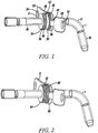
- the tube assembly comprises a tube 1 and a flange assembly 2 with a locking arrangement 25, the flange assembly being movable along the tube and lockable at different locations along its length.
- the tube 1 is made of a conventional, bendable plastics material, such as PVC, polyurethane or silicone, is hollow with a circular section and has a smooth inner surface. The outer surface may also be smooth or it could be textured to improve the grip of flange assembly 2.
- the tube 1 may have a shaft reinforced with a helical wire or similar member.
- the tube 1 is illustrated as not having any sealing cuff but it will be appreciated that the invention could be applied to a tracheostomy tube with an inflatable or other form of conventional sealing cuff. Similarly, the tube could have other conventional features, such as provision for suctioning above a cuff, fenestrations to enable speech and the like.
- the shaft of the tube 1 comprises a straight patient end region 16, a curved intermediate region 17 and a straight machine end region 18 extending at substantially 120° to the patient end region.
- Alternative shape shafts are possible, such as shafts that are curved continuously along their length or shafts that have a natural straight shape but are highly flexible so that they can conform readily to the shape of the anatomy.
- the flange assembly 2 has a rectangular central plate 20 with a central circular aperture 21 ( Figure 3 ) the diameter of which is such that the tube 1 is a close sliding fit within it.
- Two wings 22 and 23 extend from the central plate 20 on opposite sides.
- the two wings 22 and 23 are generally rectangular, being curved slightly along their length and are each formed with a lateral slot 24 towards their free end by which a tape, strap or the like can be secured to the wing.
- the two wings 22 and 23 are attached with the central plate 20 by respective flexure sections or webs 42 and 43 formed integrally with the plate and the wings.
- the webs 42 and 43 have a reduced width compared with the plate 20 and wings 22 and 23 to allow them to flex when the wings are pulled forwardly.
- the flange assembly 2 is also arranged such that the forward, patient side of the wings 22 and 23 is set forwardly relative to the forward side of the central plate 20 by 1-2mm so as to reduce pressure on the stoma site.
- the wings 22 and 23 are further designed to be relative large in area so as to help reduce pressure on any one part of the neck anatomy, which may help reduce pressure sores. The large size of the wings 22 and 23 reduces the risk of the flange becoming lost in the skin folds present in patients with a larger neck mass.
- the locking arrangement has a housing 26 with a base 27 having a central opening 28 through which the tube 1 extends freely.
- the base 27 has an outwardly-projecting lip 29 around its edge that is trapped under a ledge 30 formed around the central plate 20 of the flange 2.
- the housing 26 also has a cylindrical wall 31 extending axially of the tube 1 and open at its left-hand, rear or machine end where it is formed with a narrow, outwardly-extending retaining lip 32.
- the outer surface of the wall 31 is smooth but its inner surface is formed with a screw thread 33 that makes a single turn between the outer and inner ends of the wall.
- a manually-operable member in the form of a rotatable locking ring 34, being a part of the locking arrangement 25, is mounted on the base 27.
- the locking ring 34 has an outer collar 35 formed with knurls 36 or similar gripping formations around its outer surface.
- the collar 35 has a smooth inner surface of the same diameter as the outer diameter of the lip 32 around the wall 31, the right-hand, forward or patient end of the collar being formed with an inwardly-extending lip 36 arranged to engage the forward side of the lip around the wall when the ring 34 is in its unlocked, left, rearmost position, so as to prevent the ring coming away from the locking arrangement.
- the locking ring 34 also has an integral inner compression component in the form of an axially-extending sleeve 40.
- the external diameter of the sleeve 40 is the same as the internal diameter of the wall 31 of the housing 26 and its outer surface is formed with a screw thread form 41 that engages with the screw thread 33 around the wall.
- the sleeve 40 is longer than the outer collar 35, projecting forwardly beyond its end, being substantially the same length as wall 31 of the housing 26 within which it extends.
- the locking ring 34 In the released or unlocked position, shown in Figures 1 and 3 the locking ring 34 is in its rearmost position with the two lips 32 and 36 engaged with one another.
- the sleeve 40 extends about two thirds the way along the wall 31, its forward, patient end being spaced from the base 27.
- the sleeve 40 is stepped along its length on its inner surface between a left-hand, rear region 42 and a right-hand, forward region 43.
- the rear region 42 has an internal diameter slightly larger than the external diameter of the tube 1 so that it is a free sliding fit along the tube.
- the forward region 43 has a larger internal diameter to form an enlarged recess 44 around the tube 1 and a radially-extending, forward-facing floor or compression surface 45.
- the locking arrangement 25 is completed by a compression sleeve or ring 50 made of a compliant, resilient material with a high coefficient of friction such as neoprene.
- the sleeve 50 has a circular section and is arranged to fit within the recess 44 between the tube 1 and the locking ring 34.
- the length of the sleeve 50 is equal, to or slightly less than, the distance between the compression surface 45 on the locking ring 34 and the inside surface or floor 46 of the base 27 so that, when the locking ring 34 is in its rearmost, unlocked position, the compression ring is in its natural, uncompressed state.
- the internal diameter of the compression sleeve 50 is slightly less than the external diameter of the tube 1 so that, when the ring is in its natural, uncompressed state, the tube can slide freely through the ring.
- the external diameter of the compression sleeve 50 is equal to the internal diameter of the forward region 43 of the sleeve 40.
- the compression ring 50 is uncompressed and the flange 2 with its locking arrangement 25 is released and free to slide along the tube 1 and is free to rotate angularly about the tube 1 so that it can be positioned in the best location for the patient.
- the locking ring 34 is simply twisted clockwise to its full extent into its locking position.
- the locking ring 34 and the housing 26 may be formed with cooperating detents (not shown) at one or both extremes of travel to provide additional resistance to movement out of the fully locked or unlocked positions.
- the manually-operable means for axially compressing the sleeve 50 need not be a rotatable ring but could take other forms.
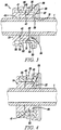
- Figures 2 and 4 show the tracheostomy tube assembly where the flange assembly 2 is locked in position along the tube 1. It can be seen that the locking ring 34 is in a forward position where the right-hand end of the sleeve 40 is in direct contact with the base 27. The effect of this forward relative displacement of the locking ring 34 is to move the compression surface 45 forwards against the rear face of the compression ring 50. This compresses the ring 50 axially between the compression surface and the floor 46 and thereby results in a force tending to expand the ring radially (Poisson effect) against both the inner surface of the forward region 43 of the sleeve 40 and against the outer surface of the tube 1.
- the force applied to the outside of the tube 1 is spread over the compressed length of the compression ring 50, typically around 6mm, so it is distributed over a relatively large area compared with previous arrangements and does not cause any localised indentation in the tube.
- the resilient nature of the compression ring 50 means that it immediately recovers its original shape and any inward compression of the tube 1 also recovers quickly without long term deformation.
- a high frictional force is exerted on the tube 1 to prevent any slipping. This is due partly to the force exerted on the tube 1 and partly due to the high coefficient of friction of the material from which the compression ring 50 is made.
- the locking arrangement could be modified by placing one or two low friction washers, such as of metal or PTFE, between the rear end of the compression ring and the compression surface of the locking ring. This would reduce twisting of the compression ring during locking.
- one or two low friction washers such as of metal or PTFE
- the invention is not confined to tracheostomy tubes but could be used with other medico-surgical tubes having a flange for supporting the tube where it emerges from the body.
Landscapes
- Health & Medical Sciences (AREA)
- Pulmonology (AREA)
- Hematology (AREA)
- Life Sciences & Earth Sciences (AREA)
- Engineering & Computer Science (AREA)
- Anesthesiology (AREA)
- Biomedical Technology (AREA)
- Heart & Thoracic Surgery (AREA)
- Veterinary Medicine (AREA)
- Emergency Medicine (AREA)
- Animal Behavior & Ethology (AREA)
- General Health & Medical Sciences (AREA)
- Public Health (AREA)
- Otolaryngology (AREA)
- Prostheses (AREA)
- Materials For Medical Uses (AREA)
Description
- This invention relates to flange assemblies of the kind that can be fitted onto and be movable along the length of a medico-surgical tube.
- Medico-surgical tubes, such as tracheostomy tubes, are commonly provided with a flange to secure the tube to the patient's body. In the case of a tracheostomy tube, the flange is positioned close to the surface of the neck where the tube enters the tracheostomy, a tape being threaded through openings in the flange and fastened around the neck. For most patients, a comfortable fit can be achieved using one of a range of several different size tubes, each having a flange mounted at a fixed location along the tube suitable for patients having an average anatomy. There are, however, some situations where a fixed flange is not suitable, such as, for example, in obese patients where tissue between the neck surface and the trachea is very thick. In these situations, it is preferable for the flange to be movable along the tube to the ideal position and to be lockable in that position. Tubes with adjustable flanges are described in, for example,
US5026352 ,US4249529 ,US4449527 ,US4498903 ,US4530354 ,US4530354 ,US4649913 ,US4683882 ,US4774944 ,WO80/02645 WO84/03217 US4278081 andWO06/087513 US8104476 describes a tube with an adjustable flange having two halves that clamped about the outside of a tube when a lever is folded flat. It is important to achieve a secure fastening of the flange to the tube even when this is wet and slippery. Because of this the flange must exert a relatively high frictional force on the outside of the tube. This can cause a problem in that the outside of the tube may be compressed by the flange, leading to a permanent or semi-permanent indentation in the outside of the tube, which may also cause a localised reduction in the diameter and cross-sectional area of the bore through the tube.GB2102490 US2008/0142003 describes a tube with an adjustable flange having a locking ring with an internal screw thread than can be rotated on an externally-threaded hub. - It is an object of the present invention to provide an alternative medico-surgical tube assembly and flange assembly for a medico-surgical tube assembly.
- According to one aspect of the present invention there is provided a flange assembly of the above-specified kind, characterised in that the flange assembly includes a locking arrangement including a housing having a base with an opening through which the tube can extend and a cylindrical wall projecting axially from the base and having an inner surface formed with a screw thread, that the locking arrangement further includes a locking ring having an outer collar extending around the outside of the housing and an inner sleeve with a screw thread on its outer surface engaged with the screw thread on the cylindrical wall, that the locking ring defines a recess between the inside of the sleeve and the outside of the tube and a radially-extending compression surface, and that the locking arrangement includes a sleeve of resilient material located in the recess such that when the locking ring is rotated it moves axially towards the base and the compression surface engages an end of the sleeve of resilient material thereby to compress the sleeve axially and deform it inwardly into gripping contact with the outside of the tube sufficient to prevent the flange assembly moving along the tube.
- According to another aspect of the present invention there is provided a medico-surgical tube assembly including a tube and a flange assembly according to the above one aspect of the present invention that is mounted on and movable along the length of the tube.
- The sleeve of resilient material may be of neoprene. The locking ring and the locking arrangement may be provided with cooperating detents arranged to retain the locking ring in the locked position. The tube may be a tracheostomy tube and the flange assembly may have two wings projecting outwardly and each provided with a formation by which the opposite ends of a neck strap can be attached to the flange assembly.
- A tracheostomy tube assembly according to the present invention will now be described, by way of example, with reference to the accompanying drawing, in which:
- Figure 1
- is a perspective view of the assembly where the flange is unlocked;
- Figure 2
- is a perspective view of the assembly with the flange locked in position;
- Figure 3
- is a cross-sectional side elevation of the flange in an unlocked state; and
- Figure 4
- is a cross-sectional side elevation of the flange in a locked state.
- With reference first to
Figure 1 , the tube assembly comprises a tube 1 and aflange assembly 2 with alocking arrangement 25, the flange assembly being movable along the tube and lockable at different locations along its length. - The tube 1 is made of a conventional, bendable plastics material, such as PVC, polyurethane or silicone, is hollow with a circular section and has a smooth inner surface. The outer surface may also be smooth or it could be textured to improve the grip of
flange assembly 2. The tube 1 may have a shaft reinforced with a helical wire or similar member. The tube 1 is illustrated as not having any sealing cuff but it will be appreciated that the invention could be applied to a tracheostomy tube with an inflatable or other form of conventional sealing cuff. Similarly, the tube could have other conventional features, such as provision for suctioning above a cuff, fenestrations to enable speech and the like. The shaft of the tube 1 comprises a straightpatient end region 16, a curvedintermediate region 17 and a straightmachine end region 18 extending at substantially 120° to the patient end region. Alternative shape shafts are possible, such as shafts that are curved continuously along their length or shafts that have a natural straight shape but are highly flexible so that they can conform readily to the shape of the anatomy. - The
flange assembly 2 has a rectangularcentral plate 20 with a central circular aperture 21 (Figure 3 ) the diameter of which is such that the tube 1 is a close sliding fit within it. Twowings central plate 20 on opposite sides. The twowings lateral slot 24 towards their free end by which a tape, strap or the like can be secured to the wing. The twowings central plate 20 by respective flexure sections orwebs webs plate 20 andwings wings webs flange assembly 2 is also arranged such that the forward, patient side of thewings central plate 20 by 1-2mm so as to reduce pressure on the stoma site. Thewings wings - With reference now also to
Figure 3 , which shows thelocking arrangement 25 of the flange in a released or unlocked state, the locking arrangement has ahousing 26 with abase 27 having acentral opening 28 through which the tube 1 extends freely. Thebase 27 has an outwardly-projectinglip 29 around its edge that is trapped under aledge 30 formed around thecentral plate 20 of theflange 2. Thehousing 26 also has acylindrical wall 31 extending axially of the tube 1 and open at its left-hand, rear or machine end where it is formed with a narrow, outwardly-extendingretaining lip 32. The outer surface of thewall 31 is smooth but its inner surface is formed with ascrew thread 33 that makes a single turn between the outer and inner ends of the wall. - A manually-operable member in the form of a
rotatable locking ring 34, being a part of thelocking arrangement 25, is mounted on thebase 27. Thelocking ring 34 has anouter collar 35 formed withknurls 36 or similar gripping formations around its outer surface. Thecollar 35 has a smooth inner surface of the same diameter as the outer diameter of thelip 32 around thewall 31, the right-hand, forward or patient end of the collar being formed with an inwardly-extendinglip 36 arranged to engage the forward side of the lip around the wall when thering 34 is in its unlocked, left, rearmost position, so as to prevent the ring coming away from the locking arrangement. Thelocking ring 34 also has an integral inner compression component in the form of an axially-extendingsleeve 40. The external diameter of thesleeve 40 is the same as the internal diameter of thewall 31 of thehousing 26 and its outer surface is formed with ascrew thread form 41 that engages with thescrew thread 33 around the wall. Thesleeve 40 is longer than theouter collar 35, projecting forwardly beyond its end, being substantially the same length aswall 31 of thehousing 26 within which it extends. In the released or unlocked position, shown inFigures 1 and3 thelocking ring 34 is in its rearmost position with the twolips sleeve 40 extends about two thirds the way along thewall 31, its forward, patient end being spaced from thebase 27. Internally, thesleeve 40 is stepped along its length on its inner surface between a left-hand,rear region 42 and a right-hand,forward region 43. Therear region 42 has an internal diameter slightly larger than the external diameter of the tube 1 so that it is a free sliding fit along the tube. Theforward region 43 has a larger internal diameter to form an enlarged recess 44 around the tube 1 and a radially-extending, forward-facing floor orcompression surface 45. - The
locking arrangement 25 is completed by a compression sleeve orring 50 made of a compliant, resilient material with a high coefficient of friction such as neoprene. Thesleeve 50 has a circular section and is arranged to fit within the recess 44 between the tube 1 and thelocking ring 34. In particular, the length of thesleeve 50 is equal, to or slightly less than, the distance between thecompression surface 45 on thelocking ring 34 and the inside surface orfloor 46 of thebase 27 so that, when thelocking ring 34 is in its rearmost, unlocked position, the compression ring is in its natural, uncompressed state. The internal diameter of thecompression sleeve 50 is slightly less than the external diameter of the tube 1 so that, when the ring is in its natural, uncompressed state, the tube can slide freely through the ring. The external diameter of thecompression sleeve 50 is equal to the internal diameter of theforward region 43 of thesleeve 40. When the lockingring 34 is in its rearmost, unlocked state the right-hand, forward end of thecompression sleeve 50 projects forwardly from the recess 44 beyond the end of thesleeve 40. In this state, thecompression ring 50 is uncompressed and theflange 2 with itslocking arrangement 25 is released and free to slide along the tube 1 and is free to rotate angularly about the tube 1 so that it can be positioned in the best location for the patient. To lock theflange 2 in the desired position the lockingring 34 is simply twisted clockwise to its full extent into its locking position. In this respect, the lockingring 34 and thehousing 26 may be formed with cooperating detents (not shown) at one or both extremes of travel to provide additional resistance to movement out of the fully locked or unlocked positions. The manually-operable means for axially compressing thesleeve 50 need not be a rotatable ring but could take other forms. -
Figures 2 and4 show the tracheostomy tube assembly where theflange assembly 2 is locked in position along the tube 1. It can be seen that the lockingring 34 is in a forward position where the right-hand end of thesleeve 40 is in direct contact with thebase 27. The effect of this forward relative displacement of the lockingring 34 is to move thecompression surface 45 forwards against the rear face of thecompression ring 50. This compresses thering 50 axially between the compression surface and thefloor 46 and thereby results in a force tending to expand the ring radially (Poisson effect) against both the inner surface of theforward region 43 of thesleeve 40 and against the outer surface of the tube 1. The force applied to the outside of the tube 1 is spread over the compressed length of thecompression ring 50, typically around 6mm, so it is distributed over a relatively large area compared with previous arrangements and does not cause any localised indentation in the tube. When the lockingring 34 is released the resilient nature of thecompression ring 50 means that it immediately recovers its original shape and any inward compression of the tube 1 also recovers quickly without long term deformation. When in the locked position a high frictional force is exerted on the tube 1 to prevent any slipping. This is due partly to the force exerted on the tube 1 and partly due to the high coefficient of friction of the material from which thecompression ring 50 is made. It will be appreciated that it would be possible to make the compression ring from a different material with a relatively low coefficient of friction if the surface contacting the tube were made high friction such as by means of a coating or a thin inner sleeve of a suitable material. This would enable a larger choice of suitable materials, some of which might have better compressibility/resilience properties but have a lower coefficient of friction. - The locking arrangement could be modified by placing one or two low friction washers, such as of metal or PTFE, between the rear end of the compression ring and the compression surface of the locking ring. This would reduce twisting of the compression ring during locking.
- The invention is not confined to tracheostomy tubes but could be used with other medico-surgical tubes having a flange for supporting the tube where it emerges from the body.
Claims (5)
- A flange assembly (2) that can be fitted onto and be movable along the length of a medico-surgical tube, wherein the flange assembly (2) includes a locking arrangement (25) including a housing (26) having a base (27) with an opening (28) through which the tube (1) can extend and a cylindrical wall (31) projecting axially from the base and having an inner surface formed with a screw thread (33), that the locking arrangement (25) further includes a locking ring (34) having an outer collar (35) extending around the outside of the housing (26) and an inner sleeve (40) with a screw thread (41) on its outer surface engaged with the screw thread (33) on the cylindrical wall (31), that the locking ring (34) defines a recess (44) between the inside of the sleeve (40) and the outside of the tube (1) and a radially-extending compression surface (45), and that the locking arrangement (25) includes a sleeve (50) of resilient material located in the recess (44) such that when the locking ring (34) is rotated it moves axially towards the base (27) and the compression surface (45) engages an end of the sleeve (50) of resilient material thereby to compress the sleeve (50) axially and deform it inwardly into gripping contact with the outside of the tube (1) sufficient to prevent the flange assembly (2) moving along the tube.
- A medico-surgical tube assembly including a tube (1) and a flange assembly (2) according to Claim 1 that is mounted on and movable along the length of the tube.
- An assembly according to Claim 1 or 2, characterised in that the sleeve (50) of resilient material is of a neoprene.
- An assembly according to any one of the preceding claims, characterised in that the locking ring (34) and the locking arrangement (25) are provided with cooperating detents arranged to retain the locking ring (34) in the locked position.
- An assembly according to any one of the preceding claims, characterised in that the tube is a tracheostomy tube (1) and the flange assembly (2) has two wings (22 and 23) projecting outwardly and each provided with a formation (24) by which opposite ends of a neck strap can be attached to the flange assembly (2).
Applications Claiming Priority (2)
| Application Number | Priority Date | Filing Date | Title |
|---|---|---|---|
| GBGB1501209.9A GB201501209D0 (en) | 2015-01-24 | 2015-01-24 | Medico-surgical tube assemblies |
| PCT/GB2015/000327 WO2016116721A1 (en) | 2015-01-24 | 2015-12-15 | Medico-surgical tube and flange assemblies |
Publications (2)
| Publication Number | Publication Date |
|---|---|
| EP3247438A1 EP3247438A1 (en) | 2017-11-29 |
| EP3247438B1 true EP3247438B1 (en) | 2019-10-02 |
Family
ID=52673893
Family Applications (1)
| Application Number | Title | Priority Date | Filing Date |
|---|---|---|---|
| EP15816490.5A Active EP3247438B1 (en) | 2015-01-24 | 2015-12-15 | Medico-surgical tube and flange assemblies |
Country Status (5)
| Country | Link |
|---|---|
| US (1) | US10603455B2 (en) |
| EP (1) | EP3247438B1 (en) |
| JP (1) | JP2018508252A (en) |
| GB (1) | GB201501209D0 (en) |
| WO (1) | WO2016116721A1 (en) |
Families Citing this family (8)
| Publication number | Priority date | Publication date | Assignee | Title |
|---|---|---|---|---|
| GB201508038D0 (en) * | 2015-05-08 | 2015-06-24 | Smiths Medical Int Ltd | Tracheostomy tube assemblies |
| GB201601583D0 (en) | 2016-01-28 | 2016-03-16 | Smiths Medical Int Ltd | Medico-surgical tube assemblies and flange assemblies |
| GB201801136D0 (en) | 2018-01-24 | 2018-03-07 | Smiths Medical International Ltd | Medico-surgical tube assemblies and mounts |
| GB202005619D0 (en) * | 2020-04-17 | 2020-06-03 | Smiths Medical International Ltd | Tracheostomy tubes and their manufacture |
| GB202006539D0 (en) * | 2020-05-04 | 2020-06-17 | Smiths Medical International Ltd | Closed-system suction catheter assemblies |
| CN112023266B (en) * | 2020-07-30 | 2025-07-11 | 创领心律管理医疗器械(上海)有限公司 | Twist assist tool |
| CN113384790A (en) * | 2021-07-01 | 2021-09-14 | 中国人民解放军空军军医大学 | Tracheal cannula adaptor and tracheal cannula |
| US20230027128A1 (en) * | 2021-07-13 | 2023-01-26 | Holly Lashmet | Endotracheal Tube and Endotracheal Sleeve and Methods of Introducing Endotracheal Tube to a Patient |
Family Cites Families (16)
| Publication number | Priority date | Publication date | Assignee | Title |
|---|---|---|---|---|
| US2693182A (en) * | 1953-09-09 | 1954-11-02 | John W Phillips | Oro-tracheal tube positioner and retainer |
| US2820457A (en) * | 1955-01-14 | 1958-01-21 | John W Phillips | Positioning retainer for oro-tracheal tubes |
| US3688774A (en) * | 1969-10-06 | 1972-09-05 | Taichiro Akiyama | Tracheotomy cannula and supporter thereof |
| US3884447A (en) * | 1973-06-06 | 1975-05-20 | Wells Mfg Corp | Fluid valve means |
| FI792308A7 (en) * | 1978-08-10 | 1981-01-01 | Smiths Industries Ltd | Breathing tube. |
| US4235229A (en) * | 1979-06-06 | 1980-11-25 | Sherwood Medical Industries Inc. | Adjustable tracheostomy tube assembly |
| GB2102490A (en) * | 1981-07-15 | 1983-02-02 | Smiths Industries Plc | Band clamps |
| US5146913A (en) * | 1991-03-04 | 1992-09-15 | Asphendiar Khorsandian | Holder and lock for oro-intubation |
| JP3279597B2 (en) * | 1991-08-21 | 2002-04-30 | アルケア株式会社 | Pouch catheter attachment brace |
| US5251616A (en) * | 1992-07-23 | 1993-10-12 | Wisconsin Alumni Research Foundation | Adjustable tracheostomy tube assembly |
| GB0503081D0 (en) * | 2005-02-15 | 2005-03-23 | Smiths Group Plc | Medico-surgical tubes |
| GB0613047D0 (en) * | 2006-07-01 | 2006-08-09 | Smiths Group Plc | Medico-surgical tube assdemblies |
| US20080142003A1 (en) | 2006-12-13 | 2008-06-19 | Arcadia Medical Corporation | MRI Compatible Airway Management Device |
| US8499763B2 (en) * | 2009-07-31 | 2013-08-06 | Covidien Lp | Connector for coupling a tracheal tube to an auxiliary device |
| DE102010049896B4 (en) * | 2010-10-29 | 2016-11-24 | Primed Halberstadt Medizintechnik Gmbh | Device in the form of a tracheostomy tube or a prosthesis for restoring the voice for insertion into a tracheostoma |
| WO2014145694A1 (en) | 2013-03-15 | 2014-09-18 | Applied Medical Technology, Inc. | Endotracheal tube retention system |
-
2015
- 2015-01-24 GB GBGB1501209.9A patent/GB201501209D0/en not_active Ceased
- 2015-12-15 JP JP2017538723A patent/JP2018508252A/en active Pending
- 2015-12-15 WO PCT/GB2015/000327 patent/WO2016116721A1/en not_active Ceased
- 2015-12-15 US US15/543,262 patent/US10603455B2/en active Active
- 2015-12-15 EP EP15816490.5A patent/EP3247438B1/en active Active
Non-Patent Citations (1)
| Title |
|---|
| None * |
Also Published As
| Publication number | Publication date |
|---|---|
| GB201501209D0 (en) | 2015-03-11 |
| US20170368284A1 (en) | 2017-12-28 |
| JP2018508252A (en) | 2018-03-29 |
| US10603455B2 (en) | 2020-03-31 |
| EP3247438A1 (en) | 2017-11-29 |
| WO2016116721A1 (en) | 2016-07-28 |
Similar Documents
| Publication | Publication Date | Title |
|---|---|---|
| US10603455B2 (en) | Medico-surgical tube and flange assemblies | |
| US10773041B2 (en) | Medico-surgical tube assemblies and flange assemblies | |
| EP2035071B1 (en) | Medico-surgical tube assemblies | |
| US8505749B2 (en) | Adjustable curtain rod | |
| US5549407A (en) | Locking mechanism for telescoping tubular poles | |
| EP2861192B1 (en) | Device for treatment of sleep apnea or snoring | |
| CN113274100B (en) | Trocar support | |
| US8734324B2 (en) | Apparatus for applying traction to a penis | |
| US10065029B2 (en) | Mechanical dilator | |
| US10894138B2 (en) | Tracheostomy tube assemblies and inner cannulae | |
| RU2661731C1 (en) | Cuff for connecting device for a penis enlargement device | |
| CN106102812B (en) | Fixtures | |
| CN209092446U (en) | Portable ventilator tube holder | |
| US20130123649A1 (en) | Cuff for a blood pressure measuring system | |
| US20180093056A1 (en) | Medico-surgical tube assemblies | |
| EP2140842A1 (en) | Apparatus for applying traction to a penis | |
| GB2102490A (en) | Band clamps | |
| WO2019145669A1 (en) | Medico-surgical tube assemblies and mounts | |
| EP4029554B1 (en) | Device for securing a peripheral venous catheter | |
| CN213609106U (en) | Breathing machine extension pipe support | |
| CN116942369A (en) | Heart valve delivery system convenient for bending adjustment | |
| JP2019076326A (en) | Urine incontinence prevention tool |
Legal Events
| Date | Code | Title | Description |
|---|---|---|---|
| STAA | Information on the status of an ep patent application or granted ep patent |
Free format text: STATUS: THE INTERNATIONAL PUBLICATION HAS BEEN MADE |
|
| PUAI | Public reference made under article 153(3) epc to a published international application that has entered the european phase |
Free format text: ORIGINAL CODE: 0009012 |
|
| STAA | Information on the status of an ep patent application or granted ep patent |
Free format text: STATUS: REQUEST FOR EXAMINATION WAS MADE |
|
| 17P | Request for examination filed |
Effective date: 20170824 |
|
| AK | Designated contracting states |
Kind code of ref document: A1 Designated state(s): AL AT BE BG CH CY CZ DE DK EE ES FI FR GB GR HR HU IE IS IT LI LT LU LV MC MK MT NL NO PL PT RO RS SE SI SK SM TR |
|
| AX | Request for extension of the european patent |
Extension state: BA ME |
|
| DAV | Request for validation of the european patent (deleted) | ||
| DAX | Request for extension of the european patent (deleted) | ||
| STAA | Information on the status of an ep patent application or granted ep patent |
Free format text: STATUS: EXAMINATION IS IN PROGRESS |
|
| 17Q | First examination report despatched |
Effective date: 20190104 |
|
| GRAP | Despatch of communication of intention to grant a patent |
Free format text: ORIGINAL CODE: EPIDOSNIGR1 |
|
| STAA | Information on the status of an ep patent application or granted ep patent |
Free format text: STATUS: GRANT OF PATENT IS INTENDED |
|
| INTG | Intention to grant announced |
Effective date: 20190529 |
|
| GRAS | Grant fee paid |
Free format text: ORIGINAL CODE: EPIDOSNIGR3 |
|
| GRAA | (expected) grant |
Free format text: ORIGINAL CODE: 0009210 |
|
| STAA | Information on the status of an ep patent application or granted ep patent |
Free format text: STATUS: THE PATENT HAS BEEN GRANTED |
|
| AK | Designated contracting states |
Kind code of ref document: B1 Designated state(s): AL AT BE BG CH CY CZ DE DK EE ES FI FR GB GR HR HU IE IS IT LI LT LU LV MC MK MT NL NO PL PT RO RS SE SI SK SM TR |
|
| REG | Reference to a national code |
Ref country code: GB Ref legal event code: FG4D |
|
| REG | Reference to a national code |
Ref country code: CH Ref legal event code: EP Ref country code: AT Ref legal event code: REF Ref document number: 1185517 Country of ref document: AT Kind code of ref document: T Effective date: 20191015 |
|
| REG | Reference to a national code |
Ref country code: IE Ref legal event code: FG4D |
|
| REG | Reference to a national code |
Ref country code: DE Ref legal event code: R096 Ref document number: 602015039195 Country of ref document: DE |
|
| REG | Reference to a national code |
Ref country code: NL Ref legal event code: MP Effective date: 20191002 |
|
| REG | Reference to a national code |
Ref country code: LT Ref legal event code: MG4D |
|
| REG | Reference to a national code |
Ref country code: AT Ref legal event code: MK05 Ref document number: 1185517 Country of ref document: AT Kind code of ref document: T Effective date: 20191002 |
|
| PG25 | Lapsed in a contracting state [announced via postgrant information from national office to epo] |
Ref country code: ES Free format text: LAPSE BECAUSE OF FAILURE TO SUBMIT A TRANSLATION OF THE DESCRIPTION OR TO PAY THE FEE WITHIN THE PRESCRIBED TIME-LIMIT Effective date: 20191002 Ref country code: AT Free format text: LAPSE BECAUSE OF FAILURE TO SUBMIT A TRANSLATION OF THE DESCRIPTION OR TO PAY THE FEE WITHIN THE PRESCRIBED TIME-LIMIT Effective date: 20191002 Ref country code: LV Free format text: LAPSE BECAUSE OF FAILURE TO SUBMIT A TRANSLATION OF THE DESCRIPTION OR TO PAY THE FEE WITHIN THE PRESCRIBED TIME-LIMIT Effective date: 20191002 Ref country code: PT Free format text: LAPSE BECAUSE OF FAILURE TO SUBMIT A TRANSLATION OF THE DESCRIPTION OR TO PAY THE FEE WITHIN THE PRESCRIBED TIME-LIMIT Effective date: 20200203 Ref country code: SE Free format text: LAPSE BECAUSE OF FAILURE TO SUBMIT A TRANSLATION OF THE DESCRIPTION OR TO PAY THE FEE WITHIN THE PRESCRIBED TIME-LIMIT Effective date: 20191002 Ref country code: BG Free format text: LAPSE BECAUSE OF FAILURE TO SUBMIT A TRANSLATION OF THE DESCRIPTION OR TO PAY THE FEE WITHIN THE PRESCRIBED TIME-LIMIT Effective date: 20200102 Ref country code: FI Free format text: LAPSE BECAUSE OF FAILURE TO SUBMIT A TRANSLATION OF THE DESCRIPTION OR TO PAY THE FEE WITHIN THE PRESCRIBED TIME-LIMIT Effective date: 20191002 Ref country code: GR Free format text: LAPSE BECAUSE OF FAILURE TO SUBMIT A TRANSLATION OF THE DESCRIPTION OR TO PAY THE FEE WITHIN THE PRESCRIBED TIME-LIMIT Effective date: 20200103 Ref country code: NO Free format text: LAPSE BECAUSE OF FAILURE TO SUBMIT A TRANSLATION OF THE DESCRIPTION OR TO PAY THE FEE WITHIN THE PRESCRIBED TIME-LIMIT Effective date: 20200102 Ref country code: PL Free format text: LAPSE BECAUSE OF FAILURE TO SUBMIT A TRANSLATION OF THE DESCRIPTION OR TO PAY THE FEE WITHIN THE PRESCRIBED TIME-LIMIT Effective date: 20191002 Ref country code: LT Free format text: LAPSE BECAUSE OF FAILURE TO SUBMIT A TRANSLATION OF THE DESCRIPTION OR TO PAY THE FEE WITHIN THE PRESCRIBED TIME-LIMIT Effective date: 20191002 Ref country code: NL Free format text: LAPSE BECAUSE OF FAILURE TO SUBMIT A TRANSLATION OF THE DESCRIPTION OR TO PAY THE FEE WITHIN THE PRESCRIBED TIME-LIMIT Effective date: 20191002 |
|
| PG25 | Lapsed in a contracting state [announced via postgrant information from national office to epo] |
Ref country code: HR Free format text: LAPSE BECAUSE OF FAILURE TO SUBMIT A TRANSLATION OF THE DESCRIPTION OR TO PAY THE FEE WITHIN THE PRESCRIBED TIME-LIMIT Effective date: 20191002 Ref country code: CZ Free format text: LAPSE BECAUSE OF FAILURE TO SUBMIT A TRANSLATION OF THE DESCRIPTION OR TO PAY THE FEE WITHIN THE PRESCRIBED TIME-LIMIT Effective date: 20191002 Ref country code: IS Free format text: LAPSE BECAUSE OF FAILURE TO SUBMIT A TRANSLATION OF THE DESCRIPTION OR TO PAY THE FEE WITHIN THE PRESCRIBED TIME-LIMIT Effective date: 20200224 Ref country code: RS Free format text: LAPSE BECAUSE OF FAILURE TO SUBMIT A TRANSLATION OF THE DESCRIPTION OR TO PAY THE FEE WITHIN THE PRESCRIBED TIME-LIMIT Effective date: 20191002 |
|
| PG25 | Lapsed in a contracting state [announced via postgrant information from national office to epo] |
Ref country code: AL Free format text: LAPSE BECAUSE OF FAILURE TO SUBMIT A TRANSLATION OF THE DESCRIPTION OR TO PAY THE FEE WITHIN THE PRESCRIBED TIME-LIMIT Effective date: 20191002 |
|
| REG | Reference to a national code |
Ref country code: DE Ref legal event code: R097 Ref document number: 602015039195 Country of ref document: DE |
|
| PG2D | Information on lapse in contracting state deleted |
Ref country code: IS |
|
| PG25 | Lapsed in a contracting state [announced via postgrant information from national office to epo] |
Ref country code: RO Free format text: LAPSE BECAUSE OF FAILURE TO SUBMIT A TRANSLATION OF THE DESCRIPTION OR TO PAY THE FEE WITHIN THE PRESCRIBED TIME-LIMIT Effective date: 20191002 Ref country code: EE Free format text: LAPSE BECAUSE OF FAILURE TO SUBMIT A TRANSLATION OF THE DESCRIPTION OR TO PAY THE FEE WITHIN THE PRESCRIBED TIME-LIMIT Effective date: 20191002 Ref country code: DK Free format text: LAPSE BECAUSE OF FAILURE TO SUBMIT A TRANSLATION OF THE DESCRIPTION OR TO PAY THE FEE WITHIN THE PRESCRIBED TIME-LIMIT Effective date: 20191002 Ref country code: IS Free format text: LAPSE BECAUSE OF FAILURE TO SUBMIT A TRANSLATION OF THE DESCRIPTION OR TO PAY THE FEE WITHIN THE PRESCRIBED TIME-LIMIT Effective date: 20200202 |
|
| REG | Reference to a national code |
Ref country code: CH Ref legal event code: PL |
|
| PLBE | No opposition filed within time limit |
Free format text: ORIGINAL CODE: 0009261 |
|
| STAA | Information on the status of an ep patent application or granted ep patent |
Free format text: STATUS: NO OPPOSITION FILED WITHIN TIME LIMIT |
|
| REG | Reference to a national code |
Ref country code: BE Ref legal event code: MM Effective date: 20191231 |
|
| PG25 | Lapsed in a contracting state [announced via postgrant information from national office to epo] |
Ref country code: SM Free format text: LAPSE BECAUSE OF FAILURE TO SUBMIT A TRANSLATION OF THE DESCRIPTION OR TO PAY THE FEE WITHIN THE PRESCRIBED TIME-LIMIT Effective date: 20191002 Ref country code: IT Free format text: LAPSE BECAUSE OF FAILURE TO SUBMIT A TRANSLATION OF THE DESCRIPTION OR TO PAY THE FEE WITHIN THE PRESCRIBED TIME-LIMIT Effective date: 20191002 Ref country code: SK Free format text: LAPSE BECAUSE OF FAILURE TO SUBMIT A TRANSLATION OF THE DESCRIPTION OR TO PAY THE FEE WITHIN THE PRESCRIBED TIME-LIMIT Effective date: 20191002 Ref country code: MC Free format text: LAPSE BECAUSE OF FAILURE TO SUBMIT A TRANSLATION OF THE DESCRIPTION OR TO PAY THE FEE WITHIN THE PRESCRIBED TIME-LIMIT Effective date: 20191002 |
|
| 26N | No opposition filed |
Effective date: 20200703 |
|
| PG25 | Lapsed in a contracting state [announced via postgrant information from national office to epo] |
Ref country code: LU Free format text: LAPSE BECAUSE OF NON-PAYMENT OF DUE FEES Effective date: 20191215 Ref country code: IE Free format text: LAPSE BECAUSE OF NON-PAYMENT OF DUE FEES Effective date: 20191215 |
|
| PG25 | Lapsed in a contracting state [announced via postgrant information from national office to epo] |
Ref country code: SI Free format text: LAPSE BECAUSE OF FAILURE TO SUBMIT A TRANSLATION OF THE DESCRIPTION OR TO PAY THE FEE WITHIN THE PRESCRIBED TIME-LIMIT Effective date: 20191002 Ref country code: LI Free format text: LAPSE BECAUSE OF NON-PAYMENT OF DUE FEES Effective date: 20191231 Ref country code: CH Free format text: LAPSE BECAUSE OF NON-PAYMENT OF DUE FEES Effective date: 20191231 Ref country code: BE Free format text: LAPSE BECAUSE OF NON-PAYMENT OF DUE FEES Effective date: 20191231 |
|
| PG25 | Lapsed in a contracting state [announced via postgrant information from national office to epo] |
Ref country code: CY Free format text: LAPSE BECAUSE OF FAILURE TO SUBMIT A TRANSLATION OF THE DESCRIPTION OR TO PAY THE FEE WITHIN THE PRESCRIBED TIME-LIMIT Effective date: 20191002 |
|
| PG25 | Lapsed in a contracting state [announced via postgrant information from national office to epo] |
Ref country code: MT Free format text: LAPSE BECAUSE OF FAILURE TO SUBMIT A TRANSLATION OF THE DESCRIPTION OR TO PAY THE FEE WITHIN THE PRESCRIBED TIME-LIMIT Effective date: 20191002 Ref country code: HU Free format text: LAPSE BECAUSE OF FAILURE TO SUBMIT A TRANSLATION OF THE DESCRIPTION OR TO PAY THE FEE WITHIN THE PRESCRIBED TIME-LIMIT; INVALID AB INITIO Effective date: 20151215 |
|
| PG25 | Lapsed in a contracting state [announced via postgrant information from national office to epo] |
Ref country code: TR Free format text: LAPSE BECAUSE OF FAILURE TO SUBMIT A TRANSLATION OF THE DESCRIPTION OR TO PAY THE FEE WITHIN THE PRESCRIBED TIME-LIMIT Effective date: 20191002 |
|
| PG25 | Lapsed in a contracting state [announced via postgrant information from national office to epo] |
Ref country code: MK Free format text: LAPSE BECAUSE OF FAILURE TO SUBMIT A TRANSLATION OF THE DESCRIPTION OR TO PAY THE FEE WITHIN THE PRESCRIBED TIME-LIMIT Effective date: 20191002 |
|
| P01 | Opt-out of the competence of the unified patent court (upc) registered |
Effective date: 20230419 |
|
| REG | Reference to a national code |
Ref country code: DE Ref legal event code: R081 Ref document number: 602015039195 Country of ref document: DE Owner name: ICU MEDICAL INTERNATIONAL LTD., ASHFORD, GB Free format text: FORMER OWNER: SMITHS MEDICAL INTERNATIONAL LTD., ASHFORD, KENT, GB |
|
| PGFP | Annual fee paid to national office [announced via postgrant information from national office to epo] |
Ref country code: DE Payment date: 20250930 Year of fee payment: 11 |
|
| PGFP | Annual fee paid to national office [announced via postgrant information from national office to epo] |
Ref country code: GB Payment date: 20251001 Year of fee payment: 11 |
|
| PGFP | Annual fee paid to national office [announced via postgrant information from national office to epo] |
Ref country code: FR Payment date: 20251008 Year of fee payment: 11 |