EP3247428B1 - Supplemental device for attachment to a pen injector and determination of a set dose amount using optical incremental encoder - Google Patents
Supplemental device for attachment to a pen injector and determination of a set dose amount using optical incremental encoder Download PDFInfo
- Publication number
- EP3247428B1 EP3247428B1 EP16701164.2A EP16701164A EP3247428B1 EP 3247428 B1 EP3247428 B1 EP 3247428B1 EP 16701164 A EP16701164 A EP 16701164A EP 3247428 B1 EP3247428 B1 EP 3247428B1
- Authority
- EP
- European Patent Office
- Prior art keywords
- medicament
- dosage
- delivery device
- medicament delivery
- medicament dosage
- Prior art date
- Legal status (The legal status is an assumption and is not a legal conclusion. Google has not performed a legal analysis and makes no representation as to the accuracy of the status listed.)
- Active
Links
Images





Classifications
-
- A—HUMAN NECESSITIES
- A61—MEDICAL OR VETERINARY SCIENCE; HYGIENE
- A61M—DEVICES FOR INTRODUCING MEDIA INTO, OR ONTO, THE BODY; DEVICES FOR TRANSDUCING BODY MEDIA OR FOR TAKING MEDIA FROM THE BODY; DEVICES FOR PRODUCING OR ENDING SLEEP OR STUPOR
- A61M5/00—Devices for bringing media into the body in a subcutaneous, intra-vascular or intramuscular way; Accessories therefor, e.g. filling or cleaning devices, arm-rests
- A61M5/178—Syringes
- A61M5/24—Ampoule syringes, i.e. syringes with needle for use in combination with replaceable ampoules or carpules, e.g. automatic
-
- A—HUMAN NECESSITIES
- A61—MEDICAL OR VETERINARY SCIENCE; HYGIENE
- A61M—DEVICES FOR INTRODUCING MEDIA INTO, OR ONTO, THE BODY; DEVICES FOR TRANSDUCING BODY MEDIA OR FOR TAKING MEDIA FROM THE BODY; DEVICES FOR PRODUCING OR ENDING SLEEP OR STUPOR
- A61M5/00—Devices for bringing media into the body in a subcutaneous, intra-vascular or intramuscular way; Accessories therefor, e.g. filling or cleaning devices, arm-rests
- A61M5/178—Syringes
- A61M5/31—Details
- A61M5/315—Pistons; Piston-rods; Guiding, blocking or restricting the movement of the rod or piston; Appliances on the rod for facilitating dosing ; Dosing mechanisms
- A61M5/31525—Dosing
-
- A—HUMAN NECESSITIES
- A61—MEDICAL OR VETERINARY SCIENCE; HYGIENE
- A61M—DEVICES FOR INTRODUCING MEDIA INTO, OR ONTO, THE BODY; DEVICES FOR TRANSDUCING BODY MEDIA OR FOR TAKING MEDIA FROM THE BODY; DEVICES FOR PRODUCING OR ENDING SLEEP OR STUPOR
- A61M5/00—Devices for bringing media into the body in a subcutaneous, intra-vascular or intramuscular way; Accessories therefor, e.g. filling or cleaning devices, arm-rests
- A61M5/178—Syringes
- A61M5/31—Details
- A61M5/315—Pistons; Piston-rods; Guiding, blocking or restricting the movement of the rod or piston; Appliances on the rod for facilitating dosing ; Dosing mechanisms
- A61M5/31533—Dosing mechanisms, i.e. setting a dose
- A61M5/31545—Setting modes for dosing
- A61M5/31548—Mechanically operated dose setting member
- A61M5/3155—Mechanically operated dose setting member by rotational movement of dose setting member, e.g. during setting or filling of a syringe
-
- A—HUMAN NECESSITIES
- A61—MEDICAL OR VETERINARY SCIENCE; HYGIENE
- A61M—DEVICES FOR INTRODUCING MEDIA INTO, OR ONTO, THE BODY; DEVICES FOR TRANSDUCING BODY MEDIA OR FOR TAKING MEDIA FROM THE BODY; DEVICES FOR PRODUCING OR ENDING SLEEP OR STUPOR
- A61M5/00—Devices for bringing media into the body in a subcutaneous, intra-vascular or intramuscular way; Accessories therefor, e.g. filling or cleaning devices, arm-rests
- A61M5/178—Syringes
- A61M5/31—Details
- A61M2005/3125—Details specific display means, e.g. to indicate dose setting
- A61M2005/3126—Specific display means related to dosing
-
- A—HUMAN NECESSITIES
- A61—MEDICAL OR VETERINARY SCIENCE; HYGIENE
- A61M—DEVICES FOR INTRODUCING MEDIA INTO, OR ONTO, THE BODY; DEVICES FOR TRANSDUCING BODY MEDIA OR FOR TAKING MEDIA FROM THE BODY; DEVICES FOR PRODUCING OR ENDING SLEEP OR STUPOR
- A61M2205/00—General characteristics of the apparatus
- A61M2205/33—Controlling, regulating or measuring
- A61M2205/3306—Optical measuring means
-
- A—HUMAN NECESSITIES
- A61—MEDICAL OR VETERINARY SCIENCE; HYGIENE
- A61M—DEVICES FOR INTRODUCING MEDIA INTO, OR ONTO, THE BODY; DEVICES FOR TRANSDUCING BODY MEDIA OR FOR TAKING MEDIA FROM THE BODY; DEVICES FOR PRODUCING OR ENDING SLEEP OR STUPOR
- A61M2205/00—General characteristics of the apparatus
- A61M2205/35—Communication
- A61M2205/3546—Range
- A61M2205/3561—Range local, e.g. within room or hospital
-
- A—HUMAN NECESSITIES
- A61—MEDICAL OR VETERINARY SCIENCE; HYGIENE
- A61M—DEVICES FOR INTRODUCING MEDIA INTO, OR ONTO, THE BODY; DEVICES FOR TRANSDUCING BODY MEDIA OR FOR TAKING MEDIA FROM THE BODY; DEVICES FOR PRODUCING OR ENDING SLEEP OR STUPOR
- A61M2205/00—General characteristics of the apparatus
- A61M2205/35—Communication
- A61M2205/3546—Range
- A61M2205/3569—Range sublocal, e.g. between console and disposable
-
- A—HUMAN NECESSITIES
- A61—MEDICAL OR VETERINARY SCIENCE; HYGIENE
- A61M—DEVICES FOR INTRODUCING MEDIA INTO, OR ONTO, THE BODY; DEVICES FOR TRANSDUCING BODY MEDIA OR FOR TAKING MEDIA FROM THE BODY; DEVICES FOR PRODUCING OR ENDING SLEEP OR STUPOR
- A61M2205/00—General characteristics of the apparatus
- A61M2205/35—Communication
- A61M2205/3576—Communication with non implanted data transmission devices, e.g. using external transmitter or receiver
- A61M2205/3584—Communication with non implanted data transmission devices, e.g. using external transmitter or receiver using modem, internet or Bluetooth®
-
- A—HUMAN NECESSITIES
- A61—MEDICAL OR VETERINARY SCIENCE; HYGIENE
- A61M—DEVICES FOR INTRODUCING MEDIA INTO, OR ONTO, THE BODY; DEVICES FOR TRANSDUCING BODY MEDIA OR FOR TAKING MEDIA FROM THE BODY; DEVICES FOR PRODUCING OR ENDING SLEEP OR STUPOR
- A61M2205/00—General characteristics of the apparatus
- A61M2205/35—Communication
- A61M2205/3576—Communication with non implanted data transmission devices, e.g. using external transmitter or receiver
- A61M2205/3592—Communication with non implanted data transmission devices, e.g. using external transmitter or receiver using telemetric means, e.g. radio or optical transmission
-
- A—HUMAN NECESSITIES
- A61—MEDICAL OR VETERINARY SCIENCE; HYGIENE
- A61M—DEVICES FOR INTRODUCING MEDIA INTO, OR ONTO, THE BODY; DEVICES FOR TRANSDUCING BODY MEDIA OR FOR TAKING MEDIA FROM THE BODY; DEVICES FOR PRODUCING OR ENDING SLEEP OR STUPOR
- A61M2205/00—General characteristics of the apparatus
- A61M2205/50—General characteristics of the apparatus with microprocessors or computers
-
- A—HUMAN NECESSITIES
- A61—MEDICAL OR VETERINARY SCIENCE; HYGIENE
- A61M—DEVICES FOR INTRODUCING MEDIA INTO, OR ONTO, THE BODY; DEVICES FOR TRANSDUCING BODY MEDIA OR FOR TAKING MEDIA FROM THE BODY; DEVICES FOR PRODUCING OR ENDING SLEEP OR STUPOR
- A61M2205/00—General characteristics of the apparatus
- A61M2205/50—General characteristics of the apparatus with microprocessors or computers
- A61M2205/502—User interfaces, e.g. screens or keyboards
-
- G—PHYSICS
- G01—MEASURING; TESTING
- G01F—MEASURING VOLUME, VOLUME FLOW, MASS FLOW OR LIQUID LEVEL; METERING BY VOLUME
- G01F23/00—Indicating or measuring liquid level or level of fluent solid material, e.g. indicating in terms of volume or indicating by means of an alarm
- G01F23/22—Indicating or measuring liquid level or level of fluent solid material, e.g. indicating in terms of volume or indicating by means of an alarm by measuring physical variables, other than linear dimensions, pressure or weight, dependent on the level to be measured, e.g. by difference of heat transfer of steam or water
- G01F23/28—Indicating or measuring liquid level or level of fluent solid material, e.g. indicating in terms of volume or indicating by means of an alarm by measuring physical variables, other than linear dimensions, pressure or weight, dependent on the level to be measured, e.g. by difference of heat transfer of steam or water by measuring the variations of parameters of electromagnetic or acoustic waves applied directly to the liquid or fluent solid material
- G01F23/284—Electromagnetic waves
- G01F23/292—Light, e.g. infrared or ultraviolet
Definitions
- the present invention relates to a data collection device for a medicament delivery device and a method for collecting medicament dosage information from a medicament delivery device.
- Such injection can be performed by using injection devices, which are applied either by medical personnel or by patients themselves.
- type-1 and type-2 diabetes can be treated by patients themselves by injection of insulin doses, for example once or several times per day.
- a pre-filled disposable insulin pen can be used as an injection device.
- a re-usable pen may be used.
- a re-usable pen allows replacement of an empty medicament cartridge by a new one.
- Either pen may come with a set of one-way needles that are replaced before each use.
- the insulin dose to be injected can then for instance be manually selected at the insulin pen by turning a dosage knob and observing the actual dose from a dosage window or display of the insulin pen.
- the dose is then injected by inserting the needle into a suited skin portion and pressing an injection button of the insulin pen.
- the injection device To be able to monitor insulin injection, for instance to prevent false handling of the insulin pen or to keep track of the doses already applied, it is desirable to measure information related to a condition and/or use of the injection device, for example, one or more of the injected insulin type, dose and timing of the injection, in a manner that is reliable and accurate.
- WO2011/117212 A1 discloses an apparatus configured for releasable attachment to a medical device or for releasably receiving at least a part of the medical device, such as an injection pen.
- the apparatus comprises one or more optical sensors for determining information relating to a condition or use of the medical device, such as a dosage to be dispensed by the device, programmed into the device by a user using optical character recognition.
- WO2013/004844 discloses a drug injection device comprising expelling means for expelling an amount of drug from a reservoir.
- the device further comprises an electronically controlled capturing system for capturing data representing the amount of drug expelled from the reservoir by the expelling means.
- WO2014/023763 discloses a pen-type drug injection device and electronic add-on monitoring module.
- the module comprises a processor and a sensor for determining the quantity of medicament that has been delivered, wherein the sensor is arranged to detect movement of a drive screw of the injection device during medicament delivery.
- WO2006/120182 discloses an injection device comprising an optically-based sensor for determining the position of a dose setting member arranged to set a dose to be injected from the injection device.
- the present invention relates to an injection device comprising a rotatably mounted member having a plurality of optically coded paths arranged on an outer surface thereof and a plurality of light sensitive elements, each configured to detect light reflected from the plurality of optically coded paths.
- WO2014/111343 discloses a pen-type drug injection device comprising a cylindrical member rotatably supported within the housing and a plurality of wherein the outer surface of the cylindrical member is provided with a track forming an encoder and having a plurality of first track segments and a plurality of second track segments arranged along the length of the track which are respectively capable of inducing first and second responses in the sensors, such that the absolute rotational position of the cylindrical member can be determined.
- the invention comprises a data collection device according to claim 1, and a method of collecting dosage information as defined in claim 6. Additional features of preferred embodiments of the invention are defined in the dependent claims.
- a data collection device configured to be attached to, or releasably receive at least part of, a medicament delivery device, the data collection device, said data collection device including at least two optical sensors, each arranged to detect light from a respective detection area, and a processing arrangement, wherein the optical sensors are configured to detect tick marks of a medicament dose indicator of the medicament delivery device in their respective detection areas, and the processing arrangement is configured to determine a current medicament dosage programmed into said medicament delivery device based on a count of the tick marks that pass through the detection areas of the optical sensors during programming of said medicament dosage into said medicament delivery device.
- the dosage is determined automatically during its programming, a user of the medicament delivery device is not required to perform an additional action to cause recordal of the dosage. For instance, the user is not required to take an image of the medicament dose indicator specifically for recording the medicament dosage.
- the processing required for determining the dosage using a "light barrier" type technique may be less complex when compared with devices that utilise a full optical character recognition algorithm, particularly as pre-processing to correct exposure levels and other parameters may not be needed.
- a camera may be provided to capture an image of at least a part of the medicament dosage indicator to determine an initial medicament dosage displayed in the window corresponds to an expected baseline amount, such as zero units, so that the absolute value of the count is known with certainty. Such a determination may be based on identification of at least one character or marking shown in the image.
- the processing arrangement may be configured to compare the captured image with a template corresponding to a predicted image of the dosage window when the expected baseline amount is displayed, to calibrate the count and/or confirm that the count of tick marks will begin with an appropriate initial value. If the captured image is not consistent with the template, an audible and/or visual alert may be generated.
- the data collection device may include a display for showing the dosage displayed by the medicament dosage indicator, since the data collection device, when attached to the medicament delivery device, may obscure the user's view of the medicament dosage window.
- the displayed dosages may be calculated based on the expected baseline amount plus a current count of tick marks detected. Determining the dosages to be displayed to the user in this manner can avoid the need for carry out a full optical character recognition process.
- An order in which the sensors detect a tick mark passing through their respective detection areas may be used to determine a direction in which the tick mark is travelling. The direction of travel can then be used to determine whether the programmed dosage is being increased or decreased.
- the data collection device may be configured to determine that the programmed dosage is not being changed if the outputs of the optical sensors are unchanged for a predetermined period of time.
- the data collection device may be configured to be releasably attached to the medicament delivery device, to allow it to be reused with other medicament delivery devices.
- the medicament delivery device is a disposable injector pen, and the data collection device can be reused with a second injector pen, or switched between injector pens as needed.
- This aspect also provides a medicament delivery system including any of the data collection devices discussed above, together with the medicament delivery device.
- the medicament delivery device may be an injector pen.
- the medicament delivery device may be a disposable injector pen.
- the data collection device may be configured for use with other medicament delivery devices.
- a method of collecting dosage information from a medicament delivery device includes, using two optical sensors, detecting tick marks of a medicament dosage indicator of the medicament delivery device, where said tick marks are present in a respective detection area of the two optical sensors, counting the tick marks that pass through the detection area during programming of a medicament dosage into the medicament delivery device, and, using a processing arrangement, determining a current medicament dosage programmed into said medicament delivery device based on a result of said count.
- the method may also include, using a processing arrangement, determining whether the current medicament dosage is increasing or decreasing, based on an order in which the optical sensors detect tick marks in said respective detection areas.
- the method may include determining an initial medicament dosage displayed by the medicament dosage indicator, wherein the processing arrangement is configured to calculate the current medicament dosage based on said initial medicament dosage and said count.
- determining an initial medicament dosage comprises capturing an image of at least a part of the medicament dosage indicator using a camera and identifying at least one character or mark in said image.
- the method may include determining whether the count has changed within a predetermined time period and, if it is determined that the count has not changed during said predetermined time period, outputting an indication of a finalised medicament dosage programmed into the medicament delivery device, wherein said finalised medicament dosage corresponds to the current medicament dosage.
- the medicament delivery device is an injector pen.
- the medicament delivery device may be a disposable injector pen for the delivery of insulin.
- the method may be used to collect dosage information from injector pens for delivering other medications or from other types of medicament delivery devices.
- Figure 1 is an exploded view of a medicament delivery device.
- the medicament delivery device is an injection device 1, such as Sanofi's SoloSTAR ® insulin injection pen.
- the injection device 1 of Figure 1 is a pre-filled, disposable injection pen that comprises a housing 10 and contains an insulin container 14, to which a needle 15 can be affixed.
- the needle is protected by an inner needle cap 16 and an outer needle cap 17, which in turn can be covered by a cap 18.
- An insulin dose to be ejected from injection device 1 can be selected by turning the dosage knob 12, and the selected dose is then displayed via dosage window 13, for instance in multiples of so-called International Units (IU), wherein one IU is the biological equivalent of about 45.5 micrograms of pure crystalline insulin (1/22 mg).
- An example of a selected dose displayed in dosage window 13 may for instance be 30 IUs, as shown in Figure 1 . It should be noted that the selected dose may equally well be displayed differently.
- the dosage window 13 may be in the form of an aperture in the housing 10, which permits a user to view a limited portion of a number sleeve 71 that is configured to move when the dosage knob 12 is turned.
- Turning the dosage knob 12 causes a mechanical click sound to provide acoustic feedback to a user.
- the number sleeve 71 mechanically interacts with a piston in insulin container 14.
- injection button 11 When needle 15 is stuck into a skin portion of a patient, and then injection button 11 is pushed, the insulin dose displayed in the dosage window 13 will be ejected from injection device 1.
- the needle 15 of injection device 1 remains for a certain time in the skin portion after the injection button 11 is pushed, a high percentage of the dose is actually injected into the patient's body. Ejection of the insulin dose also causes a mechanical click sound, which is however different from the sounds produced when using dosage knob 12.
- Injection device 1 may be used for several injection processes until either insulin container 14 is empty or the expiration date of injection device 1 (e.g. 28 days after the first use) is reached.
- injection device 1 before using injection device 1 for the first time, it may be necessary to perform a so-called "prime shot” to remove air from insulin container 14 and needle 15, for instance by selecting two units of insulin and pressing injection button 11 while holding injection device 1 with the needle 15 upwards.
- a so-called "prime shot” to remove air from insulin container 14 and needle 15, for instance by selecting two units of insulin and pressing injection button 11 while holding injection device 1 with the needle 15 upwards.
- the ejected doses substantially correspond to the injected doses, so that, for instance when making a proposal for a dose to be injected next, this dose equals the dose that has to ejected by the injection device. Nevertheless, differences (e.g. losses) between the ejected doses and the injected doses may of course be taken into account.
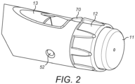
- Figure 2 is a close-up of the end of the injection device 1, showing a locating rib 70 that is located between the viewing window 13 and the dosage knob 12.
- Figure 3 shows a data collection device 2 according to an embodiment of the invention, that may be used to collect dosage information when attached to the medicament delivery device 1.
- the data collection device 2 includes two housing portions 2a, 2b connected by a hinge 2c.
- the data collection device 2 is releasably attached to the medicament device 1 by placing a part of the medicament delivery device 1 into a recess in one of the housing portions 2a, 2b and closing the housing portions 2a, 2b together around the housing 10 of the medicament delivery device 1.
- the locating rib 70 interacts with a cooperating formation 72 on the data collection device so that the data collection device 2 is located at a suitable position on the medicament delivery device 1 to collect dosage information from the dosage window 13.
- FIG. 4 is a block diagram of the data collection device 2.
- the data collection device is equipped with two or more optical sensors 25 with an associated D flip-flop 29, a camera 24 and a controller 26.
- the controller 26 is a processing arrangement including one or more processors, such as a microprocessor, a Digital Signal Processor (DSP), Application Specific Integrated Circuit (ASIC), Field Programmable Gate Array (FPGA) or the like.
- the data collection device 20 also includes memory units 240, 241, including program memory 240 and main memory 241, which can store software for execution by the controller 26.
- the data collection device 20 also includes a wireless unit 28 to permit bi-directional communication over a network, such as a personal area network or Bluetooth ® network, or a local wireless access network (WLAN).
- a display 21 and, optionally, an acoustical signal generator 23 are provided to allow visual and, if required, audio output.
- the data collection device 20 is powered by a battery 27 and a power button 22 is arranged to switch the device on and
- the components of the data collection device 20 are shown in one block in Figure 4 .
- the components are divided between the housing portions 2a, 2b of the data collection device 20.
- the display 21, the acoustical signal generator 23, where provided, and battery 27 may be provided in one of the housing portions 2a, while the controller 26, the optical sensors 25, the D flip-flop 29, the camera 24, the power button 22 and the wireless unit 28 may be provided in the other housing portion 2b.
- the division of the components of the data collection device 20 are not limited to that particular configuration.
- the housing portions 2a, 2b may include a different combination of the components than the combinations described herein.
- FIG. 5 is a circuit diagram of one optical sensor 25a in the data collection device 20 as an example.
- the optical sensor 25a includes a light source 30a, such as a light emitting diode (LED), and a photodetector 31a.
- the light source 30a emits infra-red (IR) radiation at a wavelength of 940 nm.
- IR infra-red
- the optical sensor 25a is positioned over the dosage window 13 so that light emitted from the light source 30a is incident on tick marks 50 on the number sleeve 71 within a detection area 32a of the optical sensor 25a.
- the housing portions 2a, 2b are configured to shield the detection area 32a from ambient light, to facilitate detection of the tick marks by the optical sensor 25a.
- the intensity of the light received by the photodetector 70 at a particular moment indicates whether or not a tick mark 50 is present in the detection area 32a.
- the detection area 32a is configured with a narrow width and that the intensity of the received light increases as a tick mark 50 is moved through the detection area 32a and then decreases as the tick mark 50 leaves the detection area 32a, until the next tick mark enters the detection area 32a.
- the intensity of light received by a sensor 25a may, instead, decrease as a tick mark 50 enters a detecton area 32a, depending on the reflectivity of the tick marks relative to the background on the number sleeve 71.
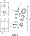
- two optical sensors 25a, 25b are provided, as shown in Figure 6 , each including a light source 30a, 30b and a photodetector 31a, 31b arranged to monitor a respective detection area 32a, 32b.
- the detection areas 32a, 32b are shown as being separated, for clarity. However, in this particular embodiment, the detection areas 32a, 32b are arranged so that a tick mark 50 that is moved through the dosage window in a first direction will be detected by a first one of the optical sensors 25b as it moves into the detection area 32b for that sensor. As the dosage continues increasing, the tick mark 50 will move into the detection area 32a of the other optical sensor 25a.
- the example shown in Figure 6 also includes a baseline detection marking 51 on the number sleeve 71, which can be used to determine whether a baseline dosage amount is shown in the dosage window 13.
- Figure 7 part (a) shows examples of the light intensities received by the optical sensors 25a, 25b, in an arrangement where the detection areas 32a, 32b are positioned closely as described above.
- tick mark 50 enters the detection area 32b
- the output of optical sensor 25b shown as a solid line
- the received light intensity remains low until a subsequent tick mark 50b enters the detection area 32b.
- tick mark 50a Before the tick mark 50a leaves detection area 32b, its leading edge moves into detection area 32a and the intensity of light received by optical sensor 25a, shown as a dashed line, also increases until the tick mark 50a leaves the detection area 32a.
- FIG. 7 parts (b) and (c) show signals output by the optical sensors 25a, 25b respectively. These signals have a high or low level depending on whether the intensity of the light received by those sensors 25a, 25b exceeds a predetermined threshold.
- the solid line depicts the output from sensor 25b, while the dashed line depicts the output from sensor 25a.
- the count is increased when a trailing edge of each tick mark 50a, 50b leaves detection area 32a.
- the timings at which the count is increased are indicated as t1 and t2.
- Figure 8 depicts the received light intensities and optical sensor outputs in an example where the user complete the programming of the dosage at time t3.
- a tick mark is present in detection area 32b but has only just begun to enter detection area 32a.
- the controller 26 is configured to detect when a predetermined period of time tx has elapsed without a change in the output signals or, alternatively, in the count itself. In this example, time tx is set to 8 seconds.
- the controller 26 determines that the finalised medicament dosage is the initial dosage adjusted by the result of the count.
- the signals from the optical sensors 25a, 25b are provided as inputs to the D flip-flop 29.
- the output from the D flip-flop 29, based on the order in which rising edges of the signals from the optical sensors 25a, 25b are detected, will be a high level or a low level and, therefore depends on the direction in which the tick marks are moved.
- the controller 26 can determine the direction of travel and whether the medicament dosage is being increased or decreased, based on the output signal from the D flip-flop 29.
- the camera 24 is used to capture an image of at least part of the dosage window 13 (step s9.1).
- This image is then processed by the controller 26 to determine whether the dosage currently displayed in the dosage window is an expected initial value (step s9.2). For example, some injector pens automatically reduce the number 19 displayed in the dosage window 13 to zero when an injection is administered, and so it would be expected that the initial value shown in the dosage window 13 before a user programs a dosage for a subsequent injection, should read zero or another expected baseline dosage amount, or display a character indicating the same. If this check is not made, then the actual dosage programmed into the injection pen 1 cannot be determined with certainty.
- a baseline detection marking 51 is included on the number sleeve 71.
- the baseline detection marking 51 may be a pattern or other mark, such as a two-dimensional code that can be detected by the camera 24, where provided.
- the baseline detection marking 51 may be visible at optical wavelengths and/or visible at other wavelengths.
- the baseline detection marking 51 is printed onto the number sleeve 71 using ink that is visible at infra-red (IR) wavelengths and the camera 24 is configured to be sensitive to IR radiation reflected from the number sleeve 71 to detect the baseline detection marking 51.
- IR infra-red
- the baseline detection marking 51 would be expected to appear at a particular position in an image captured by the camera 24 when the displayed dosage matches the expected baseline dosage amount.
- the expected baseline dosage amount is zero IU.
- the determination of whether the medicament dosage initially shown in the dosage window 13 corresponds to the expected baseline dosage amount may use the numerical characters printed on the number sleeve 71.
- one or more of the visible characters is selected, for example, the character or characters having the greatest height.
- Pattern matching is performed, based on a template stored in the one of the memories 240, 241 of the data collection device 20 that corresponds to the expected baseline dosage. Since the position of the camera 24 relative to the dosage window 13 is fixed by the locating rib 70, the selected character should provide a reasonable for the template if it corresponds to the expected baseline dosage.
- the comparison may be made on a pixel-by-pixel basis, or using a feature recognition process or a vector comparison process, for example.
- the selected character may be identified using a more elaborate optical character recognition process.
- the confirmation of the medicament dosage amount initially displayed in the dosage window 13 using a baseline detection marking 51 and/or recognition of the numerical characters on the number sleeve 71 can allow an actual value of the programmed dosage to be determined with certainty, without requiring the user to perform specific steps to calibrate the measurement to be made.
- an alert message is generated and presented on the display 21 and/or as an audible alarm using the acoustical signal generator 23 (step s9.3).
- the data collection device 20 begins to monitor the dosage window 13 using the optical sensors 25a, 25b (step s9.4) to detect tick marks 50 being moved through the detection areas 32a, 32b.
- step s9.5 If changes to the output of the optical sensors 25a, 25b are detected within the predetermined time period tx (step s9.5), then the output from the D flip-flop 29 is used to determine whether the dosage programmed into the injection pen 1 is being increased or decreased (step s9.6), as discussed herein above.
- the count is then adjusted (step s9.7) and the current dosage is determined (step s9.8).
- the output of the display 21 is updated to show the newly determined current dosage (step s9.9).
- Steps s9.4 to s9.9 are repeated, so that the count and the current dosage presented on the display 21 continue to be updated based on the detection of tick marks by the optical sensors 25a, 25b.
- the optical sensors 25a, 25b When the user has finished programming the dosage into the injection pen 1, the optical sensors 25a, 25b will not detect further changes. If time period tx has elapsed since previous changes in the optical sensors outputs (step s9.5) or, in an alternative embodiment, if there have been no changes to the count during the time period tx, then the current dosage is taken to be the final medicament dosage (step s9.10), that is, the dosage that will be administered by the user. In some embodiments, a message might be output using the display 21 and/or the acoustical signal generator 23 to prompt the user to confirm the final medicament dosage.
- the final medicament dosage is then stored (step s9.11) in the program memory 240 and, optionally, transmitted to another device (step s9.12), such as a computer, tablet device or smartphone, using the wireless unit 28.
- another device such as a computer, tablet device or smartphone
- the data collection process then ends (step s9.13).
Landscapes
- Health & Medical Sciences (AREA)
- Vascular Medicine (AREA)
- Engineering & Computer Science (AREA)
- Anesthesiology (AREA)
- Biomedical Technology (AREA)
- Heart & Thoracic Surgery (AREA)
- Hematology (AREA)
- Life Sciences & Earth Sciences (AREA)
- Animal Behavior & Ethology (AREA)
- General Health & Medical Sciences (AREA)
- Public Health (AREA)
- Veterinary Medicine (AREA)
- Infusion, Injection, And Reservoir Apparatuses (AREA)
Description
- The present invention relates to a data collection device for a medicament delivery device and a method for collecting medicament dosage information from a medicament delivery device.
- A variety of diseases exists that require regular treatment by injection of a medicament. Such injection can be performed by using injection devices, which are applied either by medical personnel or by patients themselves. As an example, type-1 and type-2 diabetes can be treated by patients themselves by injection of insulin doses, for example once or several times per day. For instance, a pre-filled disposable insulin pen can be used as an injection device. Alternatively, a re-usable pen may be used. A re-usable pen allows replacement of an empty medicament cartridge by a new one. Either pen may come with a set of one-way needles that are replaced before each use. The insulin dose to be injected can then for instance be manually selected at the insulin pen by turning a dosage knob and observing the actual dose from a dosage window or display of the insulin pen. The dose is then injected by inserting the needle into a suited skin portion and pressing an injection button of the insulin pen.
- To be able to monitor insulin injection, for instance to prevent false handling of the insulin pen or to keep track of the doses already applied, it is desirable to measure information related to a condition and/or use of the injection device, for example, one or more of the injected insulin type, dose and timing of the injection, in a manner that is reliable and accurate.
-
WO2011/117212 A1 discloses an apparatus configured for releasable attachment to a medical device or for releasably receiving at least a part of the medical device, such as an injection pen. The apparatus comprises one or more optical sensors for determining information relating to a condition or use of the medical device, such as a dosage to be dispensed by the device, programmed into the device by a user using optical character recognition. -
WO2013/004844 discloses a drug injection device comprising expelling means for expelling an amount of drug from a reservoir. The device further comprises an electronically controlled capturing system for capturing data representing the amount of drug expelled from the reservoir by the expelling means. -
WO2014/023763 discloses a pen-type drug injection device and electronic add-on monitoring module. The module comprises a processor and a sensor for determining the quantity of medicament that has been delivered, wherein the sensor is arranged to detect movement of a drive screw of the injection device during medicament delivery. -
WO2006/120182 discloses an injection device comprising an optically-based sensor for determining the position of a dose setting member arranged to set a dose to be injected from the injection device. In particular, the present invention relates to an injection device comprising a rotatably mounted member having a plurality of optically coded paths arranged on an outer surface thereof and a plurality of light sensitive elements, each configured to detect light reflected from the plurality of optically coded paths. -
WO2014/111343 discloses a pen-type drug injection device comprising a cylindrical member rotatably supported within the housing and a plurality of wherein the outer surface of the cylindrical member is provided with a track forming an encoder and having a plurality of first track segments and a plurality of second track segments arranged along the length of the track which are respectively capable of inducing first and second responses in the sensors, such that the absolute rotational position of the cylindrical member can be determined. - The invention comprises a data collection device according to
claim 1, and a method of collecting dosage information as defined in claim 6. Additional features of preferred embodiments of the invention are defined in the dependent claims. - According to one aspect, there is provided a data collection device configured to be attached to, or releasably receive at least part of, a medicament delivery device, the data collection device, said data collection device including at least two optical sensors, each arranged to detect light from a respective detection area, and a processing arrangement, wherein the optical sensors are configured to detect tick marks of a medicament dose indicator of the medicament delivery device in their respective detection areas, and the processing arrangement is configured to determine a current medicament dosage programmed into said medicament delivery device based on a count of the tick marks that pass through the detection areas of the optical sensors during programming of said medicament dosage into said medicament delivery device.
- Since the dosage is determined automatically during its programming, a user of the medicament delivery device is not required to perform an additional action to cause recordal of the dosage. For instance, the user is not required to take an image of the medicament dose indicator specifically for recording the medicament dosage.
- In addition, the processing required for determining the dosage using a "light barrier" type technique may be less complex when compared with devices that utilise a full optical character recognition algorithm, particularly as pre-processing to correct exposure levels and other parameters may not be needed.
- Also, where a camera is provided in the data collection device, the technical requirements for that camera in terms of resolution and dynamic range may be less onerous compared to cameras in devices that rely fully on optical character recognition to determine a programmed dose. For example, a camera may be provided to capture an image of at least a part of the medicament dosage indicator to determine an initial medicament dosage displayed in the window corresponds to an expected baseline amount, such as zero units, so that the absolute value of the count is known with certainty. Such a determination may be based on identification of at least one character or marking shown in the image. Since there is an expected baseline amount, the processing arrangement may be configured to compare the captured image with a template corresponding to a predicted image of the dosage window when the expected baseline amount is displayed, to calibrate the count and/or confirm that the count of tick marks will begin with an appropriate initial value. If the captured image is not consistent with the template, an audible and/or visual alert may be generated.
- Where a camera is provided, the data collection device may include a display for showing the dosage displayed by the medicament dosage indicator, since the data collection device, when attached to the medicament delivery device, may obscure the user's view of the medicament dosage window. In such an embodiment, the displayed dosages may be calculated based on the expected baseline amount plus a current count of tick marks detected. Determining the dosages to be displayed to the user in this manner can avoid the need for carry out a full optical character recognition process.
- An order in which the sensors detect a tick mark passing through their respective detection areas may be used to determine a direction in which the tick mark is travelling. The direction of travel can then be used to determine whether the programmed dosage is being increased or decreased.
- The data collection device may be configured to determine that the programmed dosage is not being changed if the outputs of the optical sensors are unchanged for a predetermined period of time.
- The data collection device may be configured to be releasably attached to the medicament delivery device, to allow it to be reused with other medicament delivery devices. In a particular example, the medicament delivery device is a disposable injector pen, and the data collection device can be reused with a second injector pen, or switched between injector pens as needed. This aspect also provides a medicament delivery system including any of the data collection devices discussed above, together with the medicament delivery device.
- The medicament delivery device may be an injector pen. In particular, the medicament delivery device may be a disposable injector pen. However, in other embodiments, the data collection device may be configured for use with other medicament delivery devices.
- According to another aspect, a method of collecting dosage information from a medicament delivery device includes, using two optical sensors, detecting tick marks of a medicament dosage indicator of the medicament delivery device, where said tick marks are present in a respective detection area of the two optical sensors, counting the tick marks that pass through the detection area during programming of a medicament dosage into the medicament delivery device, and, using a processing arrangement, determining a current medicament dosage programmed into said medicament delivery device based on a result of said count.
- The method may also include, using a processing arrangement, determining whether the current medicament dosage is increasing or decreasing, based on an order in which the optical sensors detect tick marks in said respective detection areas.
- Alternatively, or additionally, the method may include determining an initial medicament dosage displayed by the medicament dosage indicator, wherein the processing arrangement is configured to calculate the current medicament dosage based on said initial medicament dosage and said count. In one example, determining an initial medicament dosage comprises capturing an image of at least a part of the medicament dosage indicator using a camera and identifying at least one character or mark in said image.
- The method may include determining whether the count has changed within a predetermined time period and, if it is determined that the count has not changed during said predetermined time period, outputting an indication of a finalised medicament dosage programmed into the medicament delivery device, wherein said finalised medicament dosage corresponds to the current medicament dosage.
- In some embodiments, the medicament delivery device is an injector pen. For example, the medicament delivery device may be a disposable injector pen for the delivery of insulin. However, the method may be used to collect dosage information from injector pens for delivering other medications or from other types of medicament delivery devices.
- Example embodiments of the present invention will now be described with reference to the accompanying figures, of which:
-
Figure 1 is a perspective view of an example medicament delivery device from which dosage information may be collected; -
Figure 2 is a detailed view of a portion of the medicament delivery device including a dosage window; -
Figure 3 is a perspective view of a data collection device according to an embodiment of the invention, attached to the medicament delivery device shown inFigure 1 ; -
Figure 4 is a block diagram showing components of the data collection device ofFigure 3 ; -
Figure 5 depicts an example of an optical sensor that can be used in the data collection device ofFigure 3 ; -
Figure 6 shows an arrangement of two optical sensors in the data collection device ofFigure 3 ; -
Figures 7 and 8 depict intensities of light received by the optical sensors and output signals from the optical sensors in the device ofFigure 1 as a dosage is programmed into the medicament delivery device; -
Figure 9 is a flowchart of a method according to an embodiment of the invention. - In the following, embodiments of the present invention will be described with reference to collecting data from an insulin injection device, such as Sanofi's SoloSTAR® pen. The present invention is however not limited to such application and may equally well be deployed with injection devices that eject other medicaments, or other types of medicament delivery devices, or in applications other than the collection of data from medicament delivery devices, as noted hereinabove.
-
Figure 1 is an exploded view of a medicament delivery device. In this example, the medicament delivery device is aninjection device 1, such as Sanofi's SoloSTAR® insulin injection pen. - The
injection device 1 ofFigure 1 is a pre-filled, disposable injection pen that comprises ahousing 10 and contains aninsulin container 14, to which aneedle 15 can be affixed. The needle is protected by aninner needle cap 16 and anouter needle cap 17, which in turn can be covered by acap 18. An insulin dose to be ejected frominjection device 1 can be selected by turning thedosage knob 12, and the selected dose is then displayed viadosage window 13, for instance in multiples of so-called International Units (IU), wherein one IU is the biological equivalent of about 45.5 micrograms of pure crystalline insulin (1/22 mg). An example of a selected dose displayed indosage window 13 may for instance be 30 IUs, as shown inFigure 1 . It should be noted that the selected dose may equally well be displayed differently. - The
dosage window 13 may be in the form of an aperture in thehousing 10, which permits a user to view a limited portion of anumber sleeve 71 that is configured to move when thedosage knob 12 is turned. - Turning the
dosage knob 12 causes a mechanical click sound to provide acoustic feedback to a user. Thenumber sleeve 71 mechanically interacts with a piston ininsulin container 14. Whenneedle 15 is stuck into a skin portion of a patient, and theninjection button 11 is pushed, the insulin dose displayed in thedosage window 13 will be ejected frominjection device 1. When theneedle 15 ofinjection device 1 remains for a certain time in the skin portion after theinjection button 11 is pushed, a high percentage of the dose is actually injected into the patient's body. Ejection of the insulin dose also causes a mechanical click sound, which is however different from the sounds produced when usingdosage knob 12. -
Injection device 1 may be used for several injection processes until eitherinsulin container 14 is empty or the expiration date of injection device 1 (e.g. 28 days after the first use) is reached. - Furthermore, before using
injection device 1 for the first time, it may be necessary to perform a so-called "prime shot" to remove air frominsulin container 14 andneedle 15, for instance by selecting two units of insulin andpressing injection button 11 while holdinginjection device 1 with theneedle 15 upwards. - For simplicity of presentation, in the following, it will be exemplarily assumed that the ejected doses substantially correspond to the injected doses, so that, for instance when making a proposal for a dose to be injected next, this dose equals the dose that has to ejected by the injection device. Nevertheless, differences (e.g. losses) between the ejected doses and the injected doses may of course be taken into account.
-
Figure 2 is a close-up of the end of theinjection device 1, showing a locatingrib 70 that is located between the viewingwindow 13 and thedosage knob 12. -
Figure 3 shows adata collection device 2 according to an embodiment of the invention, that may be used to collect dosage information when attached to themedicament delivery device 1. - In this particular embodiment, the
data collection device 2 includes twohousing portions hinge 2c. Thedata collection device 2 is releasably attached to themedicament device 1 by placing a part of themedicament delivery device 1 into a recess in one of thehousing portions housing portions housing 10 of themedicament delivery device 1. The locatingrib 70 interacts with a cooperatingformation 72 on the data collection device so that thedata collection device 2 is located at a suitable position on themedicament delivery device 1 to collect dosage information from thedosage window 13. -
Figure 4 is a block diagram of thedata collection device 2. In this particular example, the data collection device is equipped with two or moreoptical sensors 25 with an associated D flip-flop 29, acamera 24 and acontroller 26. Thecontroller 26 is a processing arrangement including one or more processors, such as a microprocessor, a Digital Signal Processor (DSP), Application Specific Integrated Circuit (ASIC), Field Programmable Gate Array (FPGA) or the like. Thedata collection device 20 also includesmemory units program memory 240 andmain memory 241, which can store software for execution by thecontroller 26. Thedata collection device 20 also includes awireless unit 28 to permit bi-directional communication over a network, such as a personal area network or Bluetooth® network, or a local wireless access network (WLAN). Adisplay 21 and, optionally, anacoustical signal generator 23 are provided to allow visual and, if required, audio output. Thedata collection device 20 is powered by abattery 27 and apower button 22 is arranged to switch the device on and off. - For simplicity, the components of the
data collection device 20 are shown in one block inFigure 4 . In the embodiment shown inFigure 3 , the components are divided between thehousing portions data collection device 20. For example, thedisplay 21, theacoustical signal generator 23, where provided, andbattery 27 may be provided in one of thehousing portions 2a, while thecontroller 26, theoptical sensors 25, the D flip-flop 29, thecamera 24, thepower button 22 and thewireless unit 28 may be provided in theother housing portion 2b. However, the division of the components of thedata collection device 20 are not limited to that particular configuration. In other embodiments, thehousing portions -
Figure 5 is a circuit diagram of oneoptical sensor 25a in thedata collection device 20 as an example. Theoptical sensor 25a includes alight source 30a, such as a light emitting diode (LED), and aphotodetector 31a. In this particular example, thelight source 30a emits infra-red (IR) radiation at a wavelength of 940 nm. - When the
data collection device 20 is attached to themedicament delivery device 1, theoptical sensor 25a is positioned over thedosage window 13 so that light emitted from thelight source 30a is incident ontick marks 50 on thenumber sleeve 71 within adetection area 32a of theoptical sensor 25a. Preferably, thehousing portions detection area 32a from ambient light, to facilitate detection of the tick marks by theoptical sensor 25a. - Light is reflected from the
number sleeve 71 is received by thephotodetector 31a. The intensity of the light received by thephotodetector 70 at a particular moment indicates whether or not atick mark 50 is present in thedetection area 32a. In this particular example, thedetection area 32a is configured with a narrow width and that the intensity of the received light increases as atick mark 50 is moved through thedetection area 32a and then decreases as thetick mark 50 leaves thedetection area 32a, until the next tick mark enters thedetection area 32a. In other embodiments, the intensity of light received by asensor 25a may, instead, decrease as atick mark 50 enters adetecton area 32a, depending on the reflectivity of the tick marks relative to the background on thenumber sleeve 71. - In this particular embodiment, two
optical sensors Figure 6 , each including alight source 30a, 30b and aphotodetector respective detection area - In
Figure 6 , thedetection areas detection areas tick mark 50 that is moved through the dosage window in a first direction will be detected by a first one of theoptical sensors 25b as it moves into thedetection area 32b for that sensor. As the dosage continues increasing, thetick mark 50 will move into thedetection area 32a of the otheroptical sensor 25a. The example shown inFigure 6 also includes a baseline detection marking 51 on thenumber sleeve 71, which can be used to determine whether a baseline dosage amount is shown in thedosage window 13. -
Figure 7 , part (a) shows examples of the light intensities received by theoptical sensors detection areas knob 12 to increase the dosage,tick mark 50 enters thedetection area 32b, the output ofoptical sensor 25b, shown as a solid line, increases and remains high until thetick mark 50a moves out of thedetection area 32b. The received light intensity remains low until asubsequent tick mark 50b enters thedetection area 32b. - Before the
tick mark 50a leavesdetection area 32b, its leading edge moves intodetection area 32a and the intensity of light received byoptical sensor 25a, shown as a dashed line, also increases until thetick mark 50a leaves thedetection area 32a. -
Figure 7 , parts (b) and (c) show signals output by theoptical sensors sensors sensor 25b, while the dashed line depicts the output fromsensor 25a. In this particular embodiment, the count is increased when a trailing edge of eachtick mark detection area 32a. The timings at which the count is increased are indicated as t1 and t2. -
Figure 8 depicts the received light intensities and optical sensor outputs in an example where the user complete the programming of the dosage at time t3. In this particular example, a tick mark is present indetection area 32b but has only just begun to enterdetection area 32a. Thecontroller 26 is configured to detect when a predetermined period of time tx has elapsed without a change in the output signals or, alternatively, in the count itself. In this example, time tx is set to 8 seconds. - At time t4, the time period tx has elapsed, and the
controller 26 determines that the finalised medicament dosage is the initial dosage adjusted by the result of the count. - In addition to being used by the
controller 26 for the count itself, the signals from theoptical sensors flop 29. The output from the D flip-flop 29, based on the order in which rising edges of the signals from theoptical sensors controller 26 can determine the direction of travel and whether the medicament dosage is being increased or decreased, based on the output signal from the D flip-flop 29. - A method of collecting dosage information will now be described, with reference to
Figure 9 . - Starting at 9.0, the
camera 24 is used to capture an image of at least part of the dosage window 13 (step s9.1). - This image is then processed by the
controller 26 to determine whether the dosage currently displayed in the dosage window is an expected initial value (step s9.2). For example, some injector pens automatically reduce thenumber 19 displayed in thedosage window 13 to zero when an injection is administered, and so it would be expected that the initial value shown in thedosage window 13 before a user programs a dosage for a subsequent injection, should read zero or another expected baseline dosage amount, or display a character indicating the same. If this check is not made, then the actual dosage programmed into theinjection pen 1 cannot be determined with certainty. - As noted above, in this particular example a baseline detection marking 51 is included on the
number sleeve 71. The baseline detection marking 51 may be a pattern or other mark, such as a two-dimensional code that can be detected by thecamera 24, where provided. The baseline detection marking 51 may be visible at optical wavelengths and/or visible at other wavelengths. In this particular example, the baseline detection marking 51 is printed onto thenumber sleeve 71 using ink that is visible at infra-red (IR) wavelengths and thecamera 24 is configured to be sensitive to IR radiation reflected from thenumber sleeve 71 to detect the baseline detection marking 51. Since the position of thecamera 24 relative to thedosage window 13 is fixed by the locatingrib 70, the baseline detection marking 51 would be expected to appear at a particular position in an image captured by thecamera 24 when the displayed dosage matches the expected baseline dosage amount. In the example shown inFigure 6 , the expected baseline dosage amount is zero IU. - Alternatively, or additionally, the determination of whether the medicament dosage initially shown in the
dosage window 13 corresponds to the expected baseline dosage amount may use the numerical characters printed on thenumber sleeve 71. In one example, one or more of the visible characters is selected, for example, the character or characters having the greatest height. Pattern matching is performed, based on a template stored in the one of thememories data collection device 20 that corresponds to the expected baseline dosage. Since the position of thecamera 24 relative to thedosage window 13 is fixed by the locatingrib 70, the selected character should provide a reasonable for the template if it corresponds to the expected baseline dosage. The comparison may be made on a pixel-by-pixel basis, or using a feature recognition process or a vector comparison process, for example. - In another embodiment, the selected character may be identified using a more elaborate optical character recognition process.
- The confirmation of the medicament dosage amount initially displayed in the
dosage window 13 using a baseline detection marking 51 and/or recognition of the numerical characters on thenumber sleeve 71 can allow an actual value of the programmed dosage to be determined with certainty, without requiring the user to perform specific steps to calibrate the measurement to be made. - If it found that the dosage displayed in the
dosage window 13 is not consistent with the expected baseline dosage (step s9.2), an alert message is generated and presented on thedisplay 21 and/or as an audible alarm using the acoustical signal generator 23 (step s9.3). - If the displayed dosage is consistent with the expected baseline dosage (step s9.2), then the
data collection device 20 begins to monitor thedosage window 13 using theoptical sensors tick marks 50 being moved through thedetection areas - If changes to the output of the
optical sensors flop 29 is used to determine whether the dosage programmed into theinjection pen 1 is being increased or decreased (step s9.6), as discussed herein above. - The count is then adjusted (step s9.7) and the current dosage is determined (step s9.8). The output of the
display 21 is updated to show the newly determined current dosage (step s9.9). - Steps s9.4 to s9.9 are repeated, so that the count and the current dosage presented on the
display 21 continue to be updated based on the detection of tick marks by theoptical sensors - When the user has finished programming the dosage into the
injection pen 1, theoptical sensors display 21 and/or theacoustical signal generator 23 to prompt the user to confirm the final medicament dosage. - The final medicament dosage is then stored (step s9.11) in the
program memory 240 and, optionally, transmitted to another device (step s9.12), such as a computer, tablet device or smartphone, using thewireless unit 28. - The data collection process then ends (step s9.13).
- While the embodiments above have been described in relation to collecting data from an insulin injector pen, it is noted that embodiments of the invention may be used for other purposes, such as monitoring of injections of other medicaments or other medical processes.
Claims (8)
- A data collection device (2) configured to be attached to, or releasably receive at least part of, a medicament delivery device (1), the data collection device comprising:at least two optical sensors (25), each arranged to detect light from a respective detection area;a processing arrangement (26);a display (21); anda camera (24);wherein:the optical sensors are configured to detect tick marks (50) of a medicament dose indicator (71) of the medicament delivery device in their respective detection areas;the camera is configured to capture an image of at least a part of the medicament dosage indicator;the processing arrangement is configured to:determine an initial medicament dosage displayed by the medicament dosage indicator by identifying at least one character or mark shown in said image;determine whether a current medicament dosage programmed into said medicament delivery device is increasing or decreasing, based on an order in which the optical sensors detect tick marks in said respective detection areas;determine a current medicament dosage programmed into said medicament delivery device based on the initial medicament dosage, a count of the tick marks that pass through the detection areas of the optical sensors during programming of said medicament dosage into said medicament delivery device and the order in which the optical sensors detect tick marks in said respective detection areas; andthe display is configured to display the current medicament dosage in response to a change in the count.
- A data collection device according to claim 1, wherein said processing arrangement is configured to identify said at least one character based on a stored template corresponding to an expected initial medicament dosage.
- A data collection device according to claim 1 or claim 2, wherein the processing arrangement is configured to determine whether the count has changed within a predetermined time period and, if it is determined that the count has not changed during said predetermined time period, output an indication of a finalised medicament dosage programmed into the medicament delivery device, wherein said finalised medicament dosage corresponds to the current medicament dosage.
- A medicament delivery system comprising:a data collection device (2) according to any of the preceding claims; andsaid medicament delivery device (1).
- A medicament delivery system according to claim 4, wherein said medicament delivery device is an injector pen.
- A method of collecting dosage information from a medical delivery device (1), comprising:using two optical sensors (25), detecting tick marks (50) of a medicament dosage indicator (71) of the medicament delivery device, where said tick marks are present in a respective detection area of the two optical sensors;using a camera, capturing an image of at least a part of the medicament dosage indicator;determining an initial medicament dosage displayed by the medicament dosage indicator by identifying at least one character or mark shown in said image;counting the tick marks that pass through the detection area during programming of a medicament dosage into the medicament delivery device;using a processing arrangement (26), determine whether a current medicament dosage programmed into said medicament delivery device is increasing or decreasing, based on an order in which the optical sensors detect tick marks in said respective detection areas and determining a current medicament dosage programmed into said medicament delivery device based on the initial medicament dosage, a result of said count and the order in which the optical sensors detect tick marks in said respective detection areas; andusing a display, displaying the current medicament dosage in response to a change in the count.
- A method according to claim 6, comprising determining whether the count has changed within a predetermined time period and, if it is determined that the count has not changed during said predetermined time period, outputting an indication of a finalised medicament dosage programmed into the medicament delivery device, wherein said finalised medicament dosage corresponds to the current medicament dosage.
- A method according to claim 6 or 7, wherein said medicament delivery device is an injector pen.
Applications Claiming Priority (2)
| Application Number | Priority Date | Filing Date | Title |
|---|---|---|---|
| EP15151912 | 2015-01-21 | ||
| PCT/EP2016/051245 WO2016116566A1 (en) | 2015-01-21 | 2016-01-21 | Supplemental device for attachment to a pen injector and determination of a set dose amount using optical incremental encoder |
Publications (3)
| Publication Number | Publication Date |
|---|---|
| EP3247428A1 EP3247428A1 (en) | 2017-11-29 |
| EP3247428B1 true EP3247428B1 (en) | 2024-04-10 |
| EP3247428C0 EP3247428C0 (en) | 2024-04-10 |
Family
ID=52394137
Family Applications (1)
| Application Number | Title | Priority Date | Filing Date |
|---|---|---|---|
| EP16701164.2A Active EP3247428B1 (en) | 2015-01-21 | 2016-01-21 | Supplemental device for attachment to a pen injector and determination of a set dose amount using optical incremental encoder |
Country Status (4)
| Country | Link |
|---|---|
| US (2) | US10737029B2 (en) |
| EP (1) | EP3247428B1 (en) |
| JP (1) | JP7055019B2 (en) |
| WO (1) | WO2016116566A1 (en) |
Families Citing this family (17)
| Publication number | Priority date | Publication date | Assignee | Title |
|---|---|---|---|---|
| JP6616073B2 (en) | 2011-03-24 | 2019-12-04 | サノフィ−アベンティス・ドイチュラント・ゲゼルシャフト・ミット・ベシュレンクテル・ハフツング | Device and method for detecting an actuating action executable on a medical device |
| EP3058970A1 (en) * | 2015-02-19 | 2016-08-24 | Sanofi-Aventis Deutschland GmbH | Data collection device for attachment to an injection device |
| JP6901975B2 (en) | 2015-06-09 | 2021-07-14 | サノフィ−アベンティス・ドイチュラント・ゲゼルシャフト・ミット・ベシュレンクテル・ハフツング | Data acquisition device attached to the injection device |
| WO2017132577A1 (en) | 2016-01-29 | 2017-08-03 | Companion Medical, Inc. | Automatic medication delivery tracking |
| CN109689132B (en) * | 2016-09-09 | 2022-06-21 | 赛诺菲-安万特德国有限公司 | Reading device, drug delivery device and combination of drug delivery device and reading device |
| JP7069164B2 (en) | 2016-12-07 | 2022-05-17 | サノフイ | Data acquisition device for attachment to injection devices |
| US11197964B2 (en) | 2017-12-12 | 2021-12-14 | Bigfoot Biomedical, Inc. | Pen cap for medication injection pen having temperature sensor |
| US10987464B2 (en) | 2017-12-12 | 2021-04-27 | Bigfoot Biomedical, Inc. | Pen cap for insulin injection pens and associated methods and systems |
| US11464459B2 (en) | 2017-12-12 | 2022-10-11 | Bigfoot Biomedical, Inc. | User interface for diabetes management systems including flash glucose monitor |
| AU2018383743A1 (en) | 2017-12-12 | 2020-07-23 | Bigfoot Biomedical, Inc. | Therapy assist information and/or tracking device and related methods and systems |
| US11116899B2 (en) | 2017-12-12 | 2021-09-14 | Bigfoot Biomedical, Inc. | User interface for diabetes management systems and devices |
| US11083852B2 (en) | 2017-12-12 | 2021-08-10 | Bigfoot Biomedical, Inc. | Insulin injection assistance systems, methods, and devices |
| US11077243B2 (en) | 2017-12-12 | 2021-08-03 | Bigfoot Biomedical, Inc. | Devices, systems, and methods for estimating active medication from injections |
| WO2019219824A1 (en) * | 2018-05-18 | 2019-11-21 | Novo Nordisk A/S | Sensor assembly with identifier determination |
| US12205699B1 (en) | 2018-10-30 | 2025-01-21 | Bigfoot Biomedical, Inc. | Method of pairing therapy devices using shared secrets, and related systems, methods and devices |
| US11948671B2 (en) | 2019-04-11 | 2024-04-02 | Medtronic Minimed, Inc. | Intelligent accessories for medicine dispensing device |
| CN118355250A (en) * | 2021-09-24 | 2024-07-16 | 赛诺菲 | Measuring system for a drug delivery device, drug delivery device having such a measuring system, and method for measuring a dispensed dose and/or setting a dose for a drug delivery device |
Family Cites Families (15)
| Publication number | Priority date | Publication date | Assignee | Title |
|---|---|---|---|---|
| US2685083A (en) | 1951-06-05 | 1954-07-27 | Telecomputing Corp | Photoelectric signal generator for position indicators |
| US4476567A (en) * | 1981-12-11 | 1984-10-09 | The Boeing Company | Electronic protractor |
| JPH067741A (en) | 1992-06-30 | 1994-01-18 | Aisin Chem Co Ltd | Sealant coating method |
| JP3783393B2 (en) | 1998-03-17 | 2006-06-07 | 松下電器産業株式会社 | Rotation angle detector |
| JP3627531B2 (en) | 1998-09-30 | 2005-03-09 | セイコーエプソン株式会社 | Information processing device |
| EP1881859B1 (en) | 2005-05-10 | 2011-01-19 | Novo Nordisk A/S | Injection device comprising an optical sensor |
| RU2552306C2 (en) | 2008-01-23 | 2015-06-10 | Ново Нордикс А/С | Injection device for fixed dose of liquid medicinal product |
| TW201808357A (en) | 2010-03-22 | 2018-03-16 | 賽諾菲阿凡提斯德意志有限公司 | Device, method, system and computer program for drtermining information related to a medical device |
| US8525102B2 (en) * | 2011-02-15 | 2013-09-03 | Avago Technologies General Ip (Singapore) Pte. Ltd. | Optical encoding system and optical encoder having an array of incremental photodiodes and an index photodiode for use in an optical encoding system |
| EP2729202B2 (en) * | 2011-07-07 | 2024-11-06 | Novo Nordisk A/S | Drug delivery injection pen with add-on dose capturing and display module |
| KR20140122272A (en) * | 2012-02-13 | 2014-10-17 | 사노피-아벤티스 도이칠란트 게엠베하 | Supplemental device for attachment to an injection device |
| HK1211507A1 (en) * | 2012-08-10 | 2016-05-27 | Sanofi-Aventis Deutschland Gmbh | Pen-type drug injection device and electronic add-on monitoring module for monitoring and logging dose setting and administration |
| EP2945674B1 (en) * | 2013-01-15 | 2017-03-08 | Sanofi-Aventis Deutschland GmbH | Pen type drug injection device with absolute angular dose encoder mechanism |
| JP6411369B2 (en) | 2013-01-15 | 2018-10-24 | サノフィ−アベンティス・ドイチュラント・ゲゼルシャフト・ミット・ベシュレンクテル・ハフツング | Decryption system |
| CN104902944B (en) * | 2013-01-15 | 2018-10-26 | 赛诺菲-安万特德国有限公司 | Pen type drug delivery device and optical dose value decoding system with additional sensor to differentiate between dose dial mode and dose delivery mode |
-
2016
- 2016-01-21 EP EP16701164.2A patent/EP3247428B1/en active Active
- 2016-01-21 JP JP2017538298A patent/JP7055019B2/en active Active
- 2016-01-21 US US15/545,043 patent/US10737029B2/en active Active
- 2016-01-21 WO PCT/EP2016/051245 patent/WO2016116566A1/en not_active Ceased
-
2020
- 2020-08-06 US US16/987,019 patent/US11964133B2/en active Active
Also Published As
| Publication number | Publication date |
|---|---|
| US11964133B2 (en) | 2024-04-23 |
| WO2016116566A1 (en) | 2016-07-28 |
| US20180001027A1 (en) | 2018-01-04 |
| US20200360610A1 (en) | 2020-11-19 |
| US10737029B2 (en) | 2020-08-11 |
| EP3247428A1 (en) | 2017-11-29 |
| JP7055019B2 (en) | 2022-04-15 |
| JP2018504208A (en) | 2018-02-15 |
| EP3247428C0 (en) | 2024-04-10 |
Similar Documents
| Publication | Publication Date | Title |
|---|---|---|
| US11964133B2 (en) | Supplemental device for attachment to a pen injector and determination of a set dose amount using optical incremental encoder | |
| EP3219345B1 (en) | Apparatus and method for recording the amount of medicament ejected from an injection device | |
| KR101754711B1 (en) | Device and method for determining information related to a medical device | |
| JP7216692B2 (en) | Auxiliary device detachably attached to drug injection device | |
| EP2882476B1 (en) | Pen-type drug injection device and electronic add-on monitoring module for monitoring and logging dose setting and administration | |
| US20240066228A1 (en) | Drug tracking device | |
| HK1244245B (en) | Apparatus and method for recording the amount of medicament ejected from an injection device | |
| HK1218399B (en) | Apparatus and method for recording the amount of medicament ejected from an injection device | |
| HK1181282B (en) | Device and method for determining information related to a medical device | |
| HK1181282A (en) | Device and method for determining information related to a medical device |
Legal Events
| Date | Code | Title | Description |
|---|---|---|---|
| STAA | Information on the status of an ep patent application or granted ep patent |
Free format text: STATUS: THE INTERNATIONAL PUBLICATION HAS BEEN MADE |
|
| PUAI | Public reference made under article 153(3) epc to a published international application that has entered the european phase |
Free format text: ORIGINAL CODE: 0009012 |
|
| STAA | Information on the status of an ep patent application or granted ep patent |
Free format text: STATUS: REQUEST FOR EXAMINATION WAS MADE |
|
| 17P | Request for examination filed |
Effective date: 20170821 |
|
| AK | Designated contracting states |
Kind code of ref document: A1 Designated state(s): AL AT BE BG CH CY CZ DE DK EE ES FI FR GB GR HR HU IE IS IT LI LT LU LV MC MK MT NL NO PL PT RO RS SE SI SK SM TR |
|
| AX | Request for extension of the european patent |
Extension state: BA ME |
|
| DAV | Request for validation of the european patent (deleted) | ||
| DAX | Request for extension of the european patent (deleted) | ||
| STAA | Information on the status of an ep patent application or granted ep patent |
Free format text: STATUS: EXAMINATION IS IN PROGRESS |
|
| 17Q | First examination report despatched |
Effective date: 20200806 |
|
| GRAP | Despatch of communication of intention to grant a patent |
Free format text: ORIGINAL CODE: EPIDOSNIGR1 |
|
| STAA | Information on the status of an ep patent application or granted ep patent |
Free format text: STATUS: GRANT OF PATENT IS INTENDED |
|
| INTG | Intention to grant announced |
Effective date: 20231020 |
|
| GRAS | Grant fee paid |
Free format text: ORIGINAL CODE: EPIDOSNIGR3 |
|
| GRAA | (expected) grant |
Free format text: ORIGINAL CODE: 0009210 |
|
| STAA | Information on the status of an ep patent application or granted ep patent |
Free format text: STATUS: THE PATENT HAS BEEN GRANTED |
|
| AK | Designated contracting states |
Kind code of ref document: B1 Designated state(s): AL AT BE BG CH CY CZ DE DK EE ES FI FR GB GR HR HU IE IS IT LI LT LU LV MC MK MT NL NO PL PT RO RS SE SI SK SM TR |
|
| REG | Reference to a national code |
Ref country code: GB Ref legal event code: FG4D |
|
| REG | Reference to a national code |
Ref country code: CH Ref legal event code: EP |
|
| REG | Reference to a national code |
Ref country code: DE Ref legal event code: R096 Ref document number: 602016086802 Country of ref document: DE |
|
| REG | Reference to a national code |
Ref country code: IE Ref legal event code: FG4D |
|
| U01 | Request for unitary effect filed |
Effective date: 20240417 |
|
| U07 | Unitary effect registered |
Designated state(s): AT BE BG DE DK EE FI FR IT LT LU LV MT NL PT SE SI Effective date: 20240424 |
|
| PG25 | Lapsed in a contracting state [announced via postgrant information from national office to epo] |
Ref country code: IS Free format text: LAPSE BECAUSE OF FAILURE TO SUBMIT A TRANSLATION OF THE DESCRIPTION OR TO PAY THE FEE WITHIN THE PRESCRIBED TIME-LIMIT Effective date: 20240810 |
|
| PG25 | Lapsed in a contracting state [announced via postgrant information from national office to epo] |
Ref country code: HR Free format text: LAPSE BECAUSE OF FAILURE TO SUBMIT A TRANSLATION OF THE DESCRIPTION OR TO PAY THE FEE WITHIN THE PRESCRIBED TIME-LIMIT Effective date: 20240410 |
|
| PG25 | Lapsed in a contracting state [announced via postgrant information from national office to epo] |
Ref country code: GR Free format text: LAPSE BECAUSE OF FAILURE TO SUBMIT A TRANSLATION OF THE DESCRIPTION OR TO PAY THE FEE WITHIN THE PRESCRIBED TIME-LIMIT Effective date: 20240711 |
|
| PG25 | Lapsed in a contracting state [announced via postgrant information from national office to epo] |
Ref country code: ES Free format text: LAPSE BECAUSE OF FAILURE TO SUBMIT A TRANSLATION OF THE DESCRIPTION OR TO PAY THE FEE WITHIN THE PRESCRIBED TIME-LIMIT Effective date: 20240410 |
|
| PG25 | Lapsed in a contracting state [announced via postgrant information from national office to epo] |
Ref country code: PL Free format text: LAPSE BECAUSE OF FAILURE TO SUBMIT A TRANSLATION OF THE DESCRIPTION OR TO PAY THE FEE WITHIN THE PRESCRIBED TIME-LIMIT Effective date: 20240410 |
|
| PG25 | Lapsed in a contracting state [announced via postgrant information from national office to epo] |
Ref country code: PL Free format text: LAPSE BECAUSE OF FAILURE TO SUBMIT A TRANSLATION OF THE DESCRIPTION OR TO PAY THE FEE WITHIN THE PRESCRIBED TIME-LIMIT Effective date: 20240410 Ref country code: NO Free format text: LAPSE BECAUSE OF FAILURE TO SUBMIT A TRANSLATION OF THE DESCRIPTION OR TO PAY THE FEE WITHIN THE PRESCRIBED TIME-LIMIT Effective date: 20240710 Ref country code: IS Free format text: LAPSE BECAUSE OF FAILURE TO SUBMIT A TRANSLATION OF THE DESCRIPTION OR TO PAY THE FEE WITHIN THE PRESCRIBED TIME-LIMIT Effective date: 20240810 Ref country code: HR Free format text: LAPSE BECAUSE OF FAILURE TO SUBMIT A TRANSLATION OF THE DESCRIPTION OR TO PAY THE FEE WITHIN THE PRESCRIBED TIME-LIMIT Effective date: 20240410 Ref country code: GR Free format text: LAPSE BECAUSE OF FAILURE TO SUBMIT A TRANSLATION OF THE DESCRIPTION OR TO PAY THE FEE WITHIN THE PRESCRIBED TIME-LIMIT Effective date: 20240711 Ref country code: ES Free format text: LAPSE BECAUSE OF FAILURE TO SUBMIT A TRANSLATION OF THE DESCRIPTION OR TO PAY THE FEE WITHIN THE PRESCRIBED TIME-LIMIT Effective date: 20240410 Ref country code: RS Free format text: LAPSE BECAUSE OF FAILURE TO SUBMIT A TRANSLATION OF THE DESCRIPTION OR TO PAY THE FEE WITHIN THE PRESCRIBED TIME-LIMIT Effective date: 20240710 |
|
| U20 | Renewal fee for the european patent with unitary effect paid |
Year of fee payment: 10 Effective date: 20241205 |
|
| REG | Reference to a national code |
Ref country code: DE Ref legal event code: R097 Ref document number: 602016086802 Country of ref document: DE |
|
| PG25 | Lapsed in a contracting state [announced via postgrant information from national office to epo] |
Ref country code: CZ Free format text: LAPSE BECAUSE OF FAILURE TO SUBMIT A TRANSLATION OF THE DESCRIPTION OR TO PAY THE FEE WITHIN THE PRESCRIBED TIME-LIMIT Effective date: 20240410 |
|
| PG25 | Lapsed in a contracting state [announced via postgrant information from national office to epo] |
Ref country code: RO Free format text: LAPSE BECAUSE OF FAILURE TO SUBMIT A TRANSLATION OF THE DESCRIPTION OR TO PAY THE FEE WITHIN THE PRESCRIBED TIME-LIMIT Effective date: 20240410 Ref country code: SK Free format text: LAPSE BECAUSE OF FAILURE TO SUBMIT A TRANSLATION OF THE DESCRIPTION OR TO PAY THE FEE WITHIN THE PRESCRIBED TIME-LIMIT Effective date: 20240410 |
|
| PG25 | Lapsed in a contracting state [announced via postgrant information from national office to epo] |
Ref country code: SM Free format text: LAPSE BECAUSE OF FAILURE TO SUBMIT A TRANSLATION OF THE DESCRIPTION OR TO PAY THE FEE WITHIN THE PRESCRIBED TIME-LIMIT Effective date: 20240410 |
|
| PG25 | Lapsed in a contracting state [announced via postgrant information from national office to epo] |
Ref country code: SM Free format text: LAPSE BECAUSE OF FAILURE TO SUBMIT A TRANSLATION OF THE DESCRIPTION OR TO PAY THE FEE WITHIN THE PRESCRIBED TIME-LIMIT Effective date: 20240410 Ref country code: SK Free format text: LAPSE BECAUSE OF FAILURE TO SUBMIT A TRANSLATION OF THE DESCRIPTION OR TO PAY THE FEE WITHIN THE PRESCRIBED TIME-LIMIT Effective date: 20240410 Ref country code: RO Free format text: LAPSE BECAUSE OF FAILURE TO SUBMIT A TRANSLATION OF THE DESCRIPTION OR TO PAY THE FEE WITHIN THE PRESCRIBED TIME-LIMIT Effective date: 20240410 Ref country code: CZ Free format text: LAPSE BECAUSE OF FAILURE TO SUBMIT A TRANSLATION OF THE DESCRIPTION OR TO PAY THE FEE WITHIN THE PRESCRIBED TIME-LIMIT Effective date: 20240410 |
|
| PLBE | No opposition filed within time limit |
Free format text: ORIGINAL CODE: 0009261 |
|
| STAA | Information on the status of an ep patent application or granted ep patent |
Free format text: STATUS: NO OPPOSITION FILED WITHIN TIME LIMIT |
|
| 26N | No opposition filed |
Effective date: 20250113 |
|
| PG25 | Lapsed in a contracting state [announced via postgrant information from national office to epo] |
Ref country code: MC Free format text: LAPSE BECAUSE OF FAILURE TO SUBMIT A TRANSLATION OF THE DESCRIPTION OR TO PAY THE FEE WITHIN THE PRESCRIBED TIME-LIMIT Effective date: 20240410 |
|
| PGFP | Annual fee paid to national office [announced via postgrant information from national office to epo] |
Ref country code: GB Payment date: 20251204 Year of fee payment: 11 |
|
| U20 | Renewal fee for the european patent with unitary effect paid |
Year of fee payment: 11 Effective date: 20251205 |
|
| PG25 | Lapsed in a contracting state [announced via postgrant information from national office to epo] |
Ref country code: IE Free format text: LAPSE BECAUSE OF NON-PAYMENT OF DUE FEES Effective date: 20250121 |
|
| REG | Reference to a national code |
Ref country code: CH Ref legal event code: U11 Free format text: ST27 STATUS EVENT CODE: U-0-0-U10-U11 (AS PROVIDED BY THE NATIONAL OFFICE) Effective date: 20260201 |
|
| PGFP | Annual fee paid to national office [announced via postgrant information from national office to epo] |
Ref country code: CH Payment date: 20260201 Year of fee payment: 11 |