EP3247027A1 - Method of manufacturing a lamination stack for use in an electrical machine - Google Patents
Method of manufacturing a lamination stack for use in an electrical machine Download PDFInfo
- Publication number
- EP3247027A1 EP3247027A1 EP17168341.0A EP17168341A EP3247027A1 EP 3247027 A1 EP3247027 A1 EP 3247027A1 EP 17168341 A EP17168341 A EP 17168341A EP 3247027 A1 EP3247027 A1 EP 3247027A1
- Authority
- EP
- European Patent Office
- Prior art keywords
- insulating material
- sheet
- stack
- sheets
- electrical machine
- Prior art date
- Legal status (The legal status is an assumption and is not a legal conclusion. Google has not performed a legal analysis and makes no representation as to the accuracy of the status listed.)
- Granted
Links
Images

Classifications
-
- H—ELECTRICITY
- H02—GENERATION; CONVERSION OR DISTRIBUTION OF ELECTRIC POWER
- H02K—DYNAMO-ELECTRIC MACHINES
- H02K1/00—Details of the magnetic circuit
- H02K1/02—Details of the magnetic circuit characterised by the magnetic material
-
- F—MECHANICAL ENGINEERING; LIGHTING; HEATING; WEAPONS; BLASTING
- F16—ENGINEERING ELEMENTS AND UNITS; GENERAL MEASURES FOR PRODUCING AND MAINTAINING EFFECTIVE FUNCTIONING OF MACHINES OR INSTALLATIONS; THERMAL INSULATION IN GENERAL
- F16C—SHAFTS; FLEXIBLE SHAFTS; ELEMENTS OR CRANKSHAFT MECHANISMS; ROTARY BODIES OTHER THAN GEARING ELEMENTS; BEARINGS
- F16C32/00—Bearings not otherwise provided for
- F16C32/04—Bearings not otherwise provided for using magnetic or electric supporting means
- F16C32/0406—Magnetic bearings
- F16C32/044—Active magnetic bearings
- F16C32/047—Details of housings; Mounting of active magnetic bearings
-
- H—ELECTRICITY
- H02—GENERATION; CONVERSION OR DISTRIBUTION OF ELECTRIC POWER
- H02K—DYNAMO-ELECTRIC MACHINES
- H02K15/00—Processes or apparatus specially adapted for manufacturing, assembling, maintaining or repairing of dynamo-electric machines
- H02K15/02—Processes or apparatus specially adapted for manufacturing, assembling, maintaining or repairing of dynamo-electric machines of stator or rotor bodies
-
- H—ELECTRICITY
- H02—GENERATION; CONVERSION OR DISTRIBUTION OF ELECTRIC POWER
- H02K—DYNAMO-ELECTRIC MACHINES
- H02K7/00—Arrangements for handling mechanical energy structurally associated with dynamo-electric machines, e.g. structural association with mechanical driving motors or auxiliary dynamo-electric machines
- H02K7/08—Structural association with bearings
- H02K7/09—Structural association with bearings with magnetic bearings
-
- F—MECHANICAL ENGINEERING; LIGHTING; HEATING; WEAPONS; BLASTING
- F16—ENGINEERING ELEMENTS AND UNITS; GENERAL MEASURES FOR PRODUCING AND MAINTAINING EFFECTIVE FUNCTIONING OF MACHINES OR INSTALLATIONS; THERMAL INSULATION IN GENERAL
- F16C—SHAFTS; FLEXIBLE SHAFTS; ELEMENTS OR CRANKSHAFT MECHANISMS; ROTARY BODIES OTHER THAN GEARING ELEMENTS; BEARINGS
- F16C2202/00—Solid materials defined by their properties
- F16C2202/30—Electric properties; Magnetic properties
- F16C2202/40—Magnetic
-
- F—MECHANICAL ENGINEERING; LIGHTING; HEATING; WEAPONS; BLASTING
- F16—ENGINEERING ELEMENTS AND UNITS; GENERAL MEASURES FOR PRODUCING AND MAINTAINING EFFECTIVE FUNCTIONING OF MACHINES OR INSTALLATIONS; THERMAL INSULATION IN GENERAL
- F16C—SHAFTS; FLEXIBLE SHAFTS; ELEMENTS OR CRANKSHAFT MECHANISMS; ROTARY BODIES OTHER THAN GEARING ELEMENTS; BEARINGS
- F16C2204/00—Metallic materials; Alloys
- F16C2204/60—Ferrous alloys, e.g. steel alloys
-
- F—MECHANICAL ENGINEERING; LIGHTING; HEATING; WEAPONS; BLASTING
- F16—ENGINEERING ELEMENTS AND UNITS; GENERAL MEASURES FOR PRODUCING AND MAINTAINING EFFECTIVE FUNCTIONING OF MACHINES OR INSTALLATIONS; THERMAL INSULATION IN GENERAL
- F16C—SHAFTS; FLEXIBLE SHAFTS; ELEMENTS OR CRANKSHAFT MECHANISMS; ROTARY BODIES OTHER THAN GEARING ELEMENTS; BEARINGS
- F16C2208/00—Plastics; Synthetic resins, e.g. rubbers
- F16C2208/20—Thermoplastic resins
- F16C2208/30—Fluoropolymers
-
- F—MECHANICAL ENGINEERING; LIGHTING; HEATING; WEAPONS; BLASTING
- F16—ENGINEERING ELEMENTS AND UNITS; GENERAL MEASURES FOR PRODUCING AND MAINTAINING EFFECTIVE FUNCTIONING OF MACHINES OR INSTALLATIONS; THERMAL INSULATION IN GENERAL
- F16C—SHAFTS; FLEXIBLE SHAFTS; ELEMENTS OR CRANKSHAFT MECHANISMS; ROTARY BODIES OTHER THAN GEARING ELEMENTS; BEARINGS
- F16C2223/00—Surface treatments; Hardening; Coating
- F16C2223/30—Coating surfaces
-
- F—MECHANICAL ENGINEERING; LIGHTING; HEATING; WEAPONS; BLASTING
- F16—ENGINEERING ELEMENTS AND UNITS; GENERAL MEASURES FOR PRODUCING AND MAINTAINING EFFECTIVE FUNCTIONING OF MACHINES OR INSTALLATIONS; THERMAL INSULATION IN GENERAL
- F16C—SHAFTS; FLEXIBLE SHAFTS; ELEMENTS OR CRANKSHAFT MECHANISMS; ROTARY BODIES OTHER THAN GEARING ELEMENTS; BEARINGS
- F16C2223/00—Surface treatments; Hardening; Coating
- F16C2223/30—Coating surfaces
- F16C2223/32—Coating surfaces by attaching pre-existing layers, e.g. resin sheets or foils by adhesion to a substrate; Laminating
-
- F—MECHANICAL ENGINEERING; LIGHTING; HEATING; WEAPONS; BLASTING
- F16—ENGINEERING ELEMENTS AND UNITS; GENERAL MEASURES FOR PRODUCING AND MAINTAINING EFFECTIVE FUNCTIONING OF MACHINES OR INSTALLATIONS; THERMAL INSULATION IN GENERAL
- F16C—SHAFTS; FLEXIBLE SHAFTS; ELEMENTS OR CRANKSHAFT MECHANISMS; ROTARY BODIES OTHER THAN GEARING ELEMENTS; BEARINGS
- F16C2300/00—Application independent of particular apparatuses
- F16C2300/40—Application independent of particular apparatuses related to environment, i.e. operating conditions
- F16C2300/42—Application independent of particular apparatuses related to environment, i.e. operating conditions corrosive, i.e. with aggressive media or harsh conditions
-
- H—ELECTRICITY
- H02—GENERATION; CONVERSION OR DISTRIBUTION OF ELECTRIC POWER
- H02K—DYNAMO-ELECTRIC MACHINES
- H02K1/00—Details of the magnetic circuit
- H02K1/06—Details of the magnetic circuit characterised by the shape, form or construction
- H02K1/12—Stationary parts of the magnetic circuit
- H02K1/17—Stator cores with permanent magnets
-
- H—ELECTRICITY
- H02—GENERATION; CONVERSION OR DISTRIBUTION OF ELECTRIC POWER
- H02K—DYNAMO-ELECTRIC MACHINES
- H02K1/00—Details of the magnetic circuit
- H02K1/06—Details of the magnetic circuit characterised by the shape, form or construction
- H02K1/22—Rotating parts of the magnetic circuit
- H02K1/27—Rotor cores with permanent magnets
-
- H—ELECTRICITY
- H02—GENERATION; CONVERSION OR DISTRIBUTION OF ELECTRIC POWER
- H02K—DYNAMO-ELECTRIC MACHINES
- H02K2201/00—Specific aspects not provided for in the other groups of this subclass relating to the magnetic circuits
- H02K2201/09—Magnetic cores comprising laminations characterised by being fastened by caulking
Definitions
- the present invention relates to the field of rotating electrical machines, such as magnetic bearings, which comprise a magnetic bearing stator, a magnetic bearing rotor and position sensors. More specifically, the invention is directed to a method of manufacturing a lamination stack for use in a rotating electrical machine that operates in a corrosive environment or is required to be NACE-compliant.
- the bearing stator generally includes stator laminations incorporated within stator poles and copper wings. When energized, the bearing stator tends to attract the bearing rotor, on the basis of the Lenz-Faraday principle.
- the bearing rotor also comprises laminations made of soft magnetic material. The laminations are often referred to as lamination stacks and are advantageously made of soft magnetic material with excellent magnetic properties. Silicon-iron is a material that is commonly used in lamination stacks. In a corrosive environment, however, such a material cannot be used without protective measures.
- One commonly applied protective measure is to encapsulate the bearing stator and the bearing rotor, so as to isolate them from the process gas.
- stator is encapsulated by a corrosion resistant jacket and the rotor laminations are made of a magnetic anticorrosion material such as ferritic stainless steel.
- the encapsulation of the stator enables the use of silicon-iron stator laminations, but the airgap has to be enlarged in order to insert the jacket, which decreases the magnetic properties such as field sensitivity of such devices (actuator, sensor).
- ferritic stainless for the rotor laminations enables the rotor to function unshielded in the process gas, there is a compromise with regard to the magnetic properties.
- FR2888390 disclosed a method of making a laminated magnetic circuit comprising a stack of sheets of a ferromagnetic material onto which an adhesive is applied by silkscreen, then stacking the sheets, and then compressing the stack thus obtained to harden the adhesive.
- Such a laminated magnetic circuit cannot be used in a corrosive environment.
- the present invention defines a method of producing a lamination stack which has excellent corrosion resistance and excellent magnetic properties, so that the lamination stack may be used unshielded in a rotating electrical machine that operates in a corrosive environment.
- the method comprises steps of:
- the ferritic material is a ferritic stainless steel having an alloy composition in accordance with AISI 444 or EN 1.452.
- each sheet is done as follows: firstly the chemically protective electrically insulating material is disposed on the sheet in the form of solid powder, then the sheet is heated up at a temperature above the melting point of the chemically protective electrically insulating material, and finally the sheet is cooled down in ambient air.
- the preparation of both sides of each sheet is performed by a chemical attack, such as by immersion into a hydrofluoric acid bath.
- the chemically protective, electrically material is a fluoropolymer, preferably Fluorinated Ethylene Propylene, because this material doesn't react chemically with processed gas.
- each sheet of ferritic material has a thickness of between 0.05 and 3.0 mm, and each layer of chemically protective electrically insulating material has a thickness between 5 and 100 microns.
- the compression force applied during the compression of the stack is between 80 and 200 MPa.
- the present invention further defines an electrical machine that is equipped with a lamination stack produced according to the method of the invention.
- the electrical machine comprises a magnetic bearing and the lamination stack forms part of the rotor and/or stator assembly of the magnetic bearing.
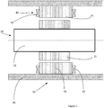
- FIG. 1 An example of part of a magnetic bearing assembly is shown in Figure 1 , the assembly 10 comprising a housing 20 in which a rotor 30 is rotationally supported by a magnetic bearing.
- the magnetic bearing comprises a stator 40 mounted to the housing 20 and disposed about the rotor 30.
- the stator 40 includes a lamination stack 41 and electromagnetic windings 42, which are wound so as to create a magnetic field when supplied with electric current.
- the rotor 30 comprises a rotor shaft 32 and a rotor lamination stack 31 which is mounted on the rotor shaft 32 and aligned with and disposed in magnetic communication with the stator 40. When appropriately energized, the stator 40 is effective to maintain the rotor lamination stack 31 in an unstable equilibrium, so as to provide levitation and radial placement of the rotor shaft 32.
- the lamination stacks of the stator 41 and the rotor 31 are made of ferritic or ferromagnetic material.
- Such ferromagnetic material can for instance be Si-Iron, Co-Iron or Ni-Iron.
- the depicted assembly 10 is part of a system that operates in a corrosive environment, such as turbo expander-compressor system applied in the oil and gas extraction sector.
- a ferritic stainless steel In order to improve the corrosion resistance of the rotor laminated stack 31 and of the stator lamination stack 41, it is advantageous to use a ferritic stainless steel.
- the ferritic stainless steel has a composition according to AISI 444 or EN 1.4521.
- This ferritic stainless steel has an alloy composition that includes:
- the lamination stacks 41, 31 have good magnetic properties.
- High relative permeability and high saturation magnetization are particularly important properties. These properties are optimized thanks to a special heat treatment, which maximises the magnetic properties of the ferritic stainless steel without compromising the corrosion resistance, the mechanical properties or electrical resistivity.
- the heat treatment consists of annealing at a temperature in excess of 900 °C followed by rapid quenching. This produces a microstructure that has fewer precipitates than the untreated base material. Furthermore, the annealing step induces grain growth, which is thought to enhance the magnetic character of the alloy. Moreover, the electrical resistivity of the material is not affected by the thermal treatment. This is an important parameter, as it is linked to eddy current losses.
- the rotor lamination stack 31 and/or the stator lamination stack 41 is manufactured according to a method that will now be described.
- a first step 100 naked sheets of a ferritic material are obtained, e.g. by stamping and cutting material from rollers of raw material in the case of metallic ferritic material.
- the geometry of the sheets, in particular their thickness, depends mainly on the desired type of lamination stack, e.g. either for a rotor or for a stator, and on the size and power of the electrical machine to be equipped with the stack.
- the thickness of the sheets is typically between 0.05 and 3 mm, and preferably between 0.1 and 0.3 mm, in order to avoid eddy currents in bearings.
- both sides of each sheet are prepared so as to obtain a determined surface roughness. Indeed, it is essential that asperities 80 are present on the surfaces of the naked sheets 60. These asperities must be in a large enough quantity and their heights and widths shall be of the order of magnitude of the micron. Typically, the heights and widths of the asperities are of about 2 microns.
- the surface roughness is too smooth and needs to be increased.
- Traditional sand blasting is unsuitable, as it would make the surface too rough by creating excessively large asperities.
- the surfaces are prepared thanks to a chemical attack consisting of an immersion of the naked sheets in a corrosive liquid bath.
- the corrosive liquid is a water solution based on hydrofluoric acid.
- a quick bath of about half an hour at room temperature suffices to create asperities of optimum dimensions.
- the sheets 60 are then removed from the bath and cleaned so as to remove any particle of corrosive liquid.
- the asperities 80 are visible on figure 4 where they have been exaggerated for the sake of clarity.
- a chemically protective, electrically insulating material is deposited on at least one side of each sheet 60.
- this material is a fluoropolymer, a material with excellent ability to resist the chemical aggression of agents such as H 2 S, NaCl and CO 2 .
- this material may be a Fluorinated Ethylene Propylene (FEP) or Perfluoroalkoxy Alkane (PFA), rather than Polytetrafluoroethylene (PTFE).
- FEP Fluorinated Ethylene Propylene
- PFA Perfluoroalkoxy Alkane
- PTFE Polytetrafluoroethylene
- the electrically insulating and chemically protective material may have the form of a very thin solid powder with grains of a few microns size (typically 5 to 10 microns), and is deposited on the sheets according to a known method such as pneumatic pulverisation or electrostatic deposition. Alternatively, a colloidal solution can be applied on the surfaces.
- Each sheet 60 is then placed in an oven or under heating lamps at the temperature exceeding the melting temperature of the insulating material for about an hour at maximum, so as to melt the grains.
- the sheets 60 are heated and maintained at a temperature of about 270°C during approximately thirty minutes. This heating temperature is low enough so as not to change the metallurgical structure of the ferritic stainless steel AISI 444 and to avoid undesired precipitates as mentioned earlier.
- the insulating material flows into or around the asperities 80.
- the insulating material solidifies and guarantees a good mechanical anchorage of the insulating material onto the sheets 60.
- coated sheets are obtained, the layer 70 of insulating material being very thin and uniform all over the face of the sheet.
- the thickness of the layer obtained according to the method of the invention is between 5 and 20 microns, depending on the desired properties of the lamination stack. Therefore, thanks to the invention, no glue is used to maintain the layer of insulating material 70 onto the ferritic sheet 60.
- each sheet 60 is to be covered by a layer 70 of insulating material, it is advantageous to use a coloured insulating material, so that the side covered is easily recognizable during the following step according to the invention.
- a coloured organic pigment is be added during the preparation of the raw insulating material.
- the use of a coloured organic pigment allows to easily control optically the presence of the insulating material. It is important to avoid the usage of colouring particles which could create electrical bridges between the sheets and hence the propagation of eddy currents. An organic colouring pigment is therefore appropriate.
- a fourth step 400 of the method of the invention the coated sheets are then stacked in a compression tool 50 represented on fig. 3 , between a lower frame 51 and upper frame 52. It is important that the coated sheets are placed horizontally so as to be perpendicular to the gravity field. For sheets with a layer of insulating material 70 on only one side, it is important that the covered side is the top one.
- a compressor 53 is then placed above the upper frame and applies a determined compression force F onto the stacked coated sheets.
- the direction of the compression force F is perpendicular to the stacked coated sheets. Thanks to the compression force, air bubbles which may have been created between the coated sheets during the stacking operation are expelled.
- Another advantage of the compression force is to minimise the distance between the sheets 60 of ferritic material while ensuring that there is always some insulating material between two consecutive sheets. Also, thanks to the compression force, a proper parallelism between the sheets 60 of ferritic material is obtained.
- the magnitude of the compression force depends on the dimensions and the number of stacked coated sheets. Typically, this compression force is chosen in the range from 80 to 200 MPa.
- the force is built thanks to a hydraulic press.
- the compression tool 50 further comprises bolts and nuts which are then screwed together until they have taken up completely the compression force F. The hydraulic press is then removed.
- a sixth step 600 of the method of the invention while maintaining the compression force on the stacked coated sheets thanks to the bolts and nuts, the assembly thus obtained is heated up and maintained at a temperature above the melting temperature of the insulating material for a few hours, a time long enough to make sure that each point of the assembly reaches the desired temperature.
- FEP FEP
- duration of between 5 and 8 hours at 350°C is recommended.
- the temperature at which the compressed stacked coated sheets are maintained shall however be lower than a temperature at which an undesirable intermetallic phase appears.
- the insulating material melts and flows into or on the asperities 80 of the naked sheet 60.
- the melted insulating material of both mixes so as to form only one melted layer with melted material still present in or on the asperities of both sheets.
- a seventh step 700 of the method of the invention the compressed assembly is then cooled down in the ambient air.
- the electrical and chemical insulating material solidifies and renders the stack of lamination unitary and rigid thanks to the mechanical anchorage of the insulating material in or on the asperities of the ferritic sheets. No glue or adhesive is used to obtain this result.
- a lamination stack that is formed according to the invention has an optimal combination of magnetic properties, mechanical properties and corrosion resistance.
- the invention has been described for its use in magnetic bearings. However, it can be implemented for any other type of rotating electrical machine such as a motor, an alternator or a generator.
Landscapes
- Engineering & Computer Science (AREA)
- Power Engineering (AREA)
- Manufacturing & Machinery (AREA)
- General Engineering & Computer Science (AREA)
- Mechanical Engineering (AREA)
- Manufacture Of Motors, Generators (AREA)
- Iron Core Of Rotating Electric Machines (AREA)
Abstract
- providing naked sheets made of ferritic material;
- preparing both sides of each sheet so as to obtain a determined surface roughness;
- coating at least one side of each sheet (60) with an chemically protective electrically insulating material;
- stacking the coated sheets;
- compressing the stack thus obtained;
- heating the compressed stack at a temperature above the melting temperature of the insulating material; and
- cooling down the compressed stack so as to form an integral lamination stack consisting of alternating sheets (60) of ferritic material and layers (70) of insulating material.
Description
- The present invention relates to the field of rotating electrical machines, such as magnetic bearings, which comprise a magnetic bearing stator, a magnetic bearing rotor and position sensors. More specifically, the invention is directed to a method of manufacturing a lamination stack for use in a rotating electrical machine that operates in a corrosive environment or is required to be NACE-compliant.
- The use of magnetic bearings in machines such as turbo-expanders and compressors is becoming increasingly common, due to the advantages associated with being able to operate the bearing in the process gas of the machine, without the need for sealing. The bearing stator generally includes stator laminations incorporated within stator poles and copper wings. When energized, the bearing stator tends to attract the bearing rotor, on the basis of the Lenz-Faraday principle. The bearing rotor also comprises laminations made of soft magnetic material. The laminations are often referred to as lamination stacks and are advantageously made of soft magnetic material with excellent magnetic properties. Silicon-iron is a material that is commonly used in lamination stacks. In a corrosive environment, however, such a material cannot be used without protective measures.
- One commonly applied protective measure is to encapsulate the bearing stator and the bearing rotor, so as to isolate them from the process gas.
- To protect the rotor laminations and rotor shaft, a solution is proposed in
CA02624347 - In
US9000642 -
FR2888390 - Consequently, there is room for improvement.
- The present invention defines a method of producing a lamination stack which has excellent corrosion resistance and excellent magnetic properties, so that the lamination stack may be used unshielded in a rotating electrical machine that operates in a corrosive environment.
- The method comprises steps of:
- providing naked sheets made of ferritic material;
- preparing both sides of each sheet so as to obtain a determined surface roughness;
- coating one side of each sheet with a chemically protective, electrically insulating material;
- stacking the coated sheets;
- compressing the stack thus obtained;
- heating the compressed stack at a temperature above the melting temperature of the insulating material; and
- cooling down the compressed stack so as to form an integral lamination stack consisting of a succession of alternating sheets of ferritic material and layers insulating material.
- In a preferred embodiment of the invention, the ferritic material is a ferritic stainless steel having an alloy composition in accordance with AISI 444 or EN 1.452.
- In a further preferred embodiment, the coating of each sheet is done as follows: firstly the chemically protective electrically insulating material is disposed on the sheet in the form of solid powder, then the sheet is heated up at a temperature above the melting point of the chemically protective electrically insulating material, and finally the sheet is cooled down in ambient air.
- In a still further preferred embodiment of the invention, the preparation of both sides of each sheet is performed by a chemical attack, such as by immersion into a hydrofluoric acid bath.
- In a still further preferred embodiment of the invention, the chemically protective, electrically material is a fluoropolymer, preferably Fluorinated Ethylene Propylene, because this material doesn't react chemically with processed gas.
- In a still further preferred embodiment of the invention, each sheet of ferritic material has a thickness of between 0.05 and 3.0 mm, and each layer of chemically protective electrically insulating material has a thickness between 5 and 100 microns.
- In a still further preferred embodiment of the invention, the compression force applied during the compression of the stack is between 80 and 200 MPa.
- The present invention further defines an electrical machine that is equipped with a lamination stack produced according to the method of the invention. In one example, the electrical machine comprises a magnetic bearing and the lamination stack forms part of the rotor and/or stator assembly of the magnetic bearing.
- As a result of the excellent corrosion resistance, the electrical machine may operate in a corrosive environment with a high degree of efficiency. Other advantages of the invention will become apparent from the following detailed description and accompanying drawings.
-
- Fig. 1
- shows a cross-sectional view of an example of an electrical machine that comprises lamination stacks manufactured using the method of the invention;
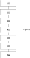
- Fig. 2
- shows a flowchart of the method of the invention;
- Fig. 3
- shows how the step of compression of the stack according to the invention is performed, with a dedicated compression tool;
- Fig. 4
- shows a magnified view of a detail of the lamination stack obtained according to the invention.
- An example of part of a magnetic bearing assembly is shown in
Figure 1 , theassembly 10 comprising ahousing 20 in which arotor 30 is rotationally supported by a magnetic bearing. The magnetic bearing comprises astator 40 mounted to thehousing 20 and disposed about therotor 30. Thestator 40 includes alamination stack 41 andelectromagnetic windings 42, which are wound so as to create a magnetic field when supplied with electric current. Therotor 30 comprises arotor shaft 32 and arotor lamination stack 31 which is mounted on therotor shaft 32 and aligned with and disposed in magnetic communication with thestator 40. When appropriately energized, thestator 40 is effective to maintain therotor lamination stack 31 in an unstable equilibrium, so as to provide levitation and radial placement of therotor shaft 32. - The lamination stacks of the
stator 41 and therotor 31 are made of ferritic or ferromagnetic material.
Such ferromagnetic material can for instance be Si-Iron, Co-Iron or Ni-Iron. - Let us assume that the depicted
assembly 10 is part of a system that operates in a corrosive environment, such as turbo expander-compressor system applied in the oil and gas extraction sector. In order to improve the corrosion resistance of the rotor laminatedstack 31 and of thestator lamination stack 41, it is advantageous to use a ferritic stainless steel. In a preferred embodiment the ferritic stainless steel has a composition according to AISI 444 or EN 1.4521. - This ferritic stainless steel has an alloy composition that includes:
- ≤ 0.025 wt.% carbon (C)
- 17.0 - 20.0 wt.% chromium (Cr)
- 1.75 - 2.50 wt.% molybdenum (Mo)
- from 0.5 to 1.0 wt.% silicon (Si)
- from 0.3 to 1.0 wt.% manganese (Mn)
- from 0 to 0.8 wt.% niobium (Nb)
- from 0 to 0.8 wt.% titanium (Ti)
- from 0 to 0.04 wt.% phosphorous (P)
- from 0 to 0.03 wt.% sulphur (S)
- from 0 to 0.035 wt.% nitrogen (N)
- For efficient functioning of the magnetic bearing, it is also important that the lamination stacks 41, 31 have good magnetic properties. High relative permeability and high saturation magnetization are particularly important properties. These properties are optimized thanks to a special heat treatment, which maximises the magnetic properties of the ferritic stainless steel without compromising the corrosion resistance, the mechanical properties or electrical resistivity.
- The heat treatment consists of annealing at a temperature in excess of 900 °C followed by rapid quenching. This produces a microstructure that has fewer precipitates than the untreated base material. Furthermore, the annealing step induces grain growth, which is thought to enhance the magnetic character of the alloy. Moreover, the electrical resistivity of the material is not affected by the thermal treatment. This is an important parameter, as it is linked to eddy current losses.
- Moreover, when ferritic stainless steel is used at elevated temperature, deleterious phases such as chi (χ) sigma (σ) and mu (µ) phases can precipitate. These phases are in equilibrium in a thermodynamic phase diagram and need time to diffuse. It is therefore important that the material does not reside long (a few minutes, 10 minutes at max, preferably 5 minutes) in the annealing temperature range where these phases are formed.
- The
rotor lamination stack 31 and/or thestator lamination stack 41 is manufactured according to a method that will now be described. - In a
first step 100, naked sheets of a ferritic material are obtained, e.g. by stamping and cutting material from rollers of raw material in the case of metallic ferritic material. The geometry of the sheets, in particular their thickness, depends mainly on the desired type of lamination stack, e.g. either for a rotor or for a stator, and on the size and power of the electrical machine to be equipped with the stack. - For a magnetic bearing to be used in an Oil & Gas extractor, the thickness of the sheets is typically between 0.05 and 3 mm, and preferably between 0.1 and 0.3 mm, in order to avoid eddy currents in bearings.
- In a
second step 200, both sides of each sheet are prepared so as to obtain a determined surface roughness. Indeed, it is essential thatasperities 80 are present on the surfaces of thenaked sheets 60. These asperities must be in a large enough quantity and their heights and widths shall be of the order of magnitude of the micron. Typically, the heights and widths of the asperities are of about 2 microns. - Depending on the ferritic raw material used and its manufacturing process, there may be the need to prepare the surfaces so as to create the
asperities 80 with dimensions mentioned above. For instance, typically with a ferritic stainless steel material, the surface roughness is too smooth and needs to be increased. Traditional sand blasting is unsuitable, as it would make the surface too rough by creating excessively large asperities. - According to the invention, the surfaces are prepared thanks to a chemical attack consisting of an immersion of the naked sheets in a corrosive liquid bath. Advantageously, the corrosive liquid is a water solution based on hydrofluoric acid. A quick bath of about half an hour at room temperature suffices to create asperities of optimum dimensions.
Thesheets 60 are then removed from the bath and cleaned so as to remove any particle of corrosive liquid. Theasperities 80 are visible onfigure 4 where they have been exaggerated for the sake of clarity. - In a
third step 300 of the method of the invention, a chemically protective, electrically insulating material is deposited on at least one side of eachsheet 60. - Advantageously, this material is a fluoropolymer, a material with excellent ability to resist the chemical aggression of agents such as H2S, NaCl and CO2. In particular, this material may be a Fluorinated Ethylene Propylene (FEP) or Perfluoroalkoxy Alkane (PFA), rather than Polytetrafluoroethylene (PTFE).
- The electrically insulating and chemically protective material may have the form of a very thin solid powder with grains of a few microns size (typically 5 to 10 microns), and is deposited on the sheets according to a known method such as pneumatic pulverisation or electrostatic deposition. Alternatively, a colloidal solution can be applied on the surfaces.
- Each
sheet 60 is then placed in an oven or under heating lamps at the temperature exceeding the melting temperature of the insulating material for about an hour at maximum, so as to melt the grains. For instance, in the case of FEP, which has a melting temperature of 260°C, thesheets 60 are heated and maintained at a temperature of about 270°C during approximately thirty minutes. This heating temperature is low enough so as not to change the metallurgical structure of the ferritic stainless steel AISI 444 and to avoid undesired precipitates as mentioned earlier.
Once melted the insulating material flows into or around theasperities 80. Upon cooling, preferably in the ambient air, the insulating material solidifies and guarantees a good mechanical anchorage of the insulating material onto thesheets 60. Hence, coated sheets are obtained, thelayer 70 of insulating material being very thin and uniform all over the face of the sheet. The thickness of the layer obtained according to the method of the invention is between 5 and 20 microns, depending on the desired properties of the lamination stack.
Therefore, thanks to the invention, no glue is used to maintain the layer of insulatingmaterial 70 onto theferritic sheet 60. - In the case where only one face of each
sheet 60 is to be covered by alayer 70 of insulating material, it is advantageous to use a coloured insulating material, so that the side covered is easily recognizable during the following step according to the invention. In the case where the basic insulating material is not coloured (this is the case for FEP), a coloured organic pigment is be added during the preparation of the raw insulating material.
In the case where the two faces of eachsheet 60 is to be covered by a layer of insulating material, the use of a coloured organic pigment allows to easily control optically the presence of the insulating material.
It is important to avoid the usage of colouring particles which could create electrical bridges between the sheets and hence the propagation of eddy currents. An organic colouring pigment is therefore appropriate. - In a
fourth step 400 of the method of the invention, the coated sheets are then stacked in acompression tool 50 represented onfig. 3 , between alower frame 51 andupper frame 52. It is important that the coated sheets are placed horizontally so as to be perpendicular to the gravity field. For sheets with a layer of insulatingmaterial 70 on only one side, it is important that the covered side is the top one. - In a
fifth step 500 of the method of the invention, acompressor 53 is then placed above the upper frame and applies a determined compression force F onto the stacked coated sheets. The direction of the compression force F is perpendicular to the stacked coated sheets. Thanks to the compression force, air bubbles which may have been created between the coated sheets during the stacking operation are expelled. Another advantage of the compression force is to minimise the distance between thesheets 60 of ferritic material while ensuring that there is always some insulating material between two consecutive sheets. Also, thanks to the compression force, a proper parallelism between thesheets 60 of ferritic material is obtained. - The magnitude of the compression force depends on the dimensions and the number of stacked coated sheets. Typically, this compression force is chosen in the range from 80 to 200 MPa. The force is built thanks to a hydraulic press. The
compression tool 50 further comprises bolts and nuts which are then screwed together until they have taken up completely the compression force F. The hydraulic press is then removed. - In a
sixth step 600 of the method of the invention, while maintaining the compression force on the stacked coated sheets thanks to the bolts and nuts, the assembly thus obtained is heated up and maintained at a temperature above the melting temperature of the insulating material for a few hours, a time long enough to make sure that each point of the assembly reaches the desired temperature. When FEP is used, duration of between 5 and 8 hours at 350°C is recommended. The temperature at which the compressed stacked coated sheets are maintained shall however be lower than a temperature at which an undesirable intermetallic phase appears. - When one
layer 70 of insulating material belonging to a coated sheet is in direct contact with anaked sheet 60, the insulating material melts and flows into or on theasperities 80 of thenaked sheet 60.
When two layers of insulating material belonging to two consecutive coated sheets are in contact, the melted insulating material of both mixes so as to form only one melted layer with melted material still present in or on the asperities of both sheets. - In a
seventh step 700 of the method of the invention, the compressed assembly is then cooled down in the ambient air. During the cooling, the electrical and chemical insulating material solidifies and renders the stack of lamination unitary and rigid thanks to the mechanical anchorage of the insulating material in or on the asperities of the ferritic sheets. No glue or adhesive is used to obtain this result. - The use of solid grains of only a few microns size of chemically protective, electrically insulating material permits to deposit a minimum quantity of it on the naked ferritic sheets, so as to form a layer of a minimum thickness, of about 5 to 20 microns, large enough just to isolate electrically two consecutive ferritic sheets and to ensure the mechanical stiffness of the lamination stack.
- If necessary, further machining operations can be performed on the lamination stack obtained by a method according to the invention, in order to give the stack its final dimensions.
- Consequently, a lamination stack that is formed according to the invention has an optimal combination of magnetic properties, mechanical properties and corrosion resistance.
- The invention has been described for its use in magnetic bearings. However, it can be implemented for any other type of rotating electrical machine such as a motor, an alternator or a generator.
-
- 10
- assembly
- 20
- housing
- 30
- rotor
- 31
- rotor lamination stack
- 32
- rotor shaft
- 40
- stator
- 41
- stator lamination stack
- 42
- stator electromagnetic windings
- 50
- compression tool
- 51
- lower frame
- 52
- upper frame
- 53
- compressor
- 60
- sheet
- 70
- layer of chemically protective insulating material
- 80
- asperities
- F
- compression force
Claims (10)
- A method of manufacturing a lamination stack (31, 41) for use in a rotating electrical machine (10), the method comprising steps of:- providing naked sheets made of ferritic material;- preparing both sides of each sheet so as to obtain a determined surface roughness;- coating at least one side of each sheet (60) with a chemically protective electrically insulating material;- stacking the coated sheets;- compressing the stack thus obtained;- heating the compressed stack at a temperature above the melting temperature of the insulating material; and- cooling down the compressed stack so as to form an integral lamination stack (31, 41) consisting of alternating sheets (60) of ferritic material and layers (70) of insulating material.
- Method according to claim 1, characterized in that the preparation of both sides of each sheet is performed by chemical attack, for instance by immersion into a hydrofluoric acid bath.
- Method according to any preceding claim, characterized in that the coating of at least one side of each sheet consists of the following successive steps:a. the chemically protective electrically insulating material is disposed on the sheet in the form of solid powder,b. the thus obtained sheet is heated to a temperature above the melting point of insulating material, andc. the sheet is cooled down in ambient air.
- Method according to any preceding claim, characterized in that the compression force applied during the compression of the stack is between 80 and 200 MPa.
- Method according to any preceding claim, characterized in that the chemically protective insulating material is a fluoropolymer such as Fluorinated Ethylene Propylene.
- Method according to any preceding claim, characterized in that each sheet (60) of ferritic material has a thickness of between 0.05 and 3.0 mm, and each layer (70) of chemically protective, electrically insulating material has a thickness between 5 and 100 microns.
- Method according to any preceding claim, wherein the ferritic material is a ferritic stainless steel having an alloy composition in accordance with AISI 444 or EN 1.452, and further comprising a step of heat treatment of the naked sheets during which their magnetic properties are enhanced.
- An electrical machine (10) comprising a lamination stack (31, 41) that is manufactured in accordance with the method of any preceding claim.
- The electrical machine of claim 8, wherein the electrical machine comprises a magnetic bearing having a magnetic bearing stator (40) and a magnetic bearing rotor (30).
- The electrical machine of claim 9, wherein the lamination stack (41) forms part of the magnetic bearing stator (40) and/or the magnetic bearing rotor (30).
Applications Claiming Priority (1)
| Application Number | Priority Date | Filing Date | Title |
|---|---|---|---|
| DE102016208744 | 2016-05-20 |
Publications (2)
| Publication Number | Publication Date |
|---|---|
| EP3247027A1 true EP3247027A1 (en) | 2017-11-22 |
| EP3247027B1 EP3247027B1 (en) | 2022-11-30 |
Family
ID=58692332
Family Applications (1)
| Application Number | Title | Priority Date | Filing Date |
|---|---|---|---|
| EP17168341.0A Active EP3247027B1 (en) | 2016-05-20 | 2017-04-27 | Method of manufacturing a lamination stack for use in an electrical machine |
Country Status (4)
| Country | Link |
|---|---|
| US (2) | US10897164B2 (en) |
| EP (1) | EP3247027B1 (en) |
| CN (1) | CN107401554B (en) |
| CA (1) | CA2962212C (en) |
Cited By (1)
| Publication number | Priority date | Publication date | Assignee | Title |
|---|---|---|---|---|
| CN112242759A (en) * | 2020-09-25 | 2021-01-19 | 兰州万里航空机电有限责任公司 | Insulation and anti-corrosion structure of a brushless DC motor immersed in coolant |
Families Citing this family (1)
| Publication number | Priority date | Publication date | Assignee | Title |
|---|---|---|---|---|
| EP3595132A1 (en) * | 2018-07-13 | 2020-01-15 | Siemens Aktiengesellschaft | Material layer for high rotational speeds and method for producing |
Citations (6)
| Publication number | Priority date | Publication date | Assignee | Title |
|---|---|---|---|---|
| US3512902A (en) * | 1968-04-22 | 1970-05-19 | Smith Corp A O | Inductive core device and method of making the same |
| US4085347A (en) * | 1976-01-16 | 1978-04-18 | White-Westinghouse Corporation | Laminated stator core |
| FR2888390A1 (en) | 2005-07-08 | 2007-01-12 | Cnes Epic | METHOD FOR MANUFACTURING MAGNETIC LAMINATE CIRCUIT |
| CA2624347A1 (en) | 2007-03-08 | 2008-09-08 | General Electric Company | Rotor shaft assembly for magnetic bearings for use in corrosive environments |
| US20140062253A1 (en) * | 2012-08-31 | 2014-03-06 | Calnetix Technologies, Llc | Constructing an Electric Machine |
| US9000642B2 (en) | 2011-05-13 | 2015-04-07 | Skf Magnetic Mechatronics | Corrosion-resistant jacketed active magnetic bearing |
Family Cites Families (12)
| Publication number | Priority date | Publication date | Assignee | Title |
|---|---|---|---|---|
| CN1003833B (en) * | 1985-08-21 | 1989-04-05 | 株式会社日立制作所 | DC motor with permanent magnetic field system |
| JPH0821494B2 (en) * | 1988-08-04 | 1996-03-04 | 日鉱金属株式会社 | Laminated magnetic core and method for manufacturing laminated magnetic core |
| DE69919677T2 (en) * | 1998-09-14 | 2005-09-08 | Asahi Glass Co., Ltd. | METHOD FOR PRODUCING A DOUBLE-LAYER CAPACITY WITH HIGH CAPACITY |
| JP2000144204A (en) * | 1998-11-13 | 2000-05-26 | Sumitomo Special Metals Co Ltd | Production of sintered soft ferrite material |
| US7160279B2 (en) * | 1999-10-07 | 2007-01-09 | Playtex Products, Inc. | Rapid expansion tampon pledget comprising inverted coverstock and pleats |
| US20040115477A1 (en) * | 2002-12-12 | 2004-06-17 | Bruce Nesbitt | Coating reinforcing underlayment and method of manufacturing same |
| US7777383B2 (en) * | 2005-08-24 | 2010-08-17 | Doris Wilsdorf | MP-A and MP-T machines, multipolar machines for alternating and three-phase currents |
| FR2897911B1 (en) | 2006-02-27 | 2009-03-27 | Mecanique Magnetique Sa Soc D | ACTIVE MAGNETIC BEARING SHIRT |
| CA2606276A1 (en) * | 2007-10-11 | 2009-04-11 | General Electric Company | Magnetic bearings, armatures for magnetic bearings, and methods for assembling the same |
| JP5702913B2 (en) * | 2009-03-30 | 2015-04-15 | 双信電機株式会社 | Ferrite materials and electronic components |
| US20110175358A1 (en) * | 2010-01-15 | 2011-07-21 | Richard Langson | One and two-stage direct gas and steam screw expander generator system (dsg) |
| EP3054030B1 (en) | 2015-02-03 | 2018-10-31 | Skf Magnetic Mechatronics | Method of protecting lamination stacks of a component of an electric machine |
-
2017
- 2017-03-27 CA CA2962212A patent/CA2962212C/en active Active
- 2017-04-07 CN CN201710223389.XA patent/CN107401554B/en active Active
- 2017-04-27 EP EP17168341.0A patent/EP3247027B1/en active Active
- 2017-05-17 US US15/597,275 patent/US10897164B2/en active Active
-
2020
- 2020-12-14 US US17/121,148 patent/US11728696B2/en active Active
Patent Citations (6)
| Publication number | Priority date | Publication date | Assignee | Title |
|---|---|---|---|---|
| US3512902A (en) * | 1968-04-22 | 1970-05-19 | Smith Corp A O | Inductive core device and method of making the same |
| US4085347A (en) * | 1976-01-16 | 1978-04-18 | White-Westinghouse Corporation | Laminated stator core |
| FR2888390A1 (en) | 2005-07-08 | 2007-01-12 | Cnes Epic | METHOD FOR MANUFACTURING MAGNETIC LAMINATE CIRCUIT |
| CA2624347A1 (en) | 2007-03-08 | 2008-09-08 | General Electric Company | Rotor shaft assembly for magnetic bearings for use in corrosive environments |
| US9000642B2 (en) | 2011-05-13 | 2015-04-07 | Skf Magnetic Mechatronics | Corrosion-resistant jacketed active magnetic bearing |
| US20140062253A1 (en) * | 2012-08-31 | 2014-03-06 | Calnetix Technologies, Llc | Constructing an Electric Machine |
Cited By (2)
| Publication number | Priority date | Publication date | Assignee | Title |
|---|---|---|---|---|
| CN112242759A (en) * | 2020-09-25 | 2021-01-19 | 兰州万里航空机电有限责任公司 | Insulation and anti-corrosion structure of a brushless DC motor immersed in coolant |
| CN112242759B (en) * | 2020-09-25 | 2022-03-08 | 兰州万里航空机电有限责任公司 | Insulating and anti-corrosion structure of immersed cooling liquid brushless direct current motor |
Also Published As
| Publication number | Publication date |
|---|---|
| CN107401554B (en) | 2020-08-14 |
| CA2962212C (en) | 2024-05-14 |
| CN107401554A (en) | 2017-11-28 |
| EP3247027B1 (en) | 2022-11-30 |
| US10897164B2 (en) | 2021-01-19 |
| US11728696B2 (en) | 2023-08-15 |
| CA2962212A1 (en) | 2017-11-20 |
| US20210099032A1 (en) | 2021-04-01 |
| US20170338699A1 (en) | 2017-11-23 |
Similar Documents
| Publication | Publication Date | Title |
|---|---|---|
| US11975386B2 (en) | Structures utilizing a structured magnetic material and methods for making | |
| EP1540793B1 (en) | Method of constructing a unitary amorphous metal component for an electric machine | |
| US6946097B2 (en) | High-strength high-temperature creep-resistant iron-cobalt alloys for soft magnetic applications | |
| KR101395413B1 (en) | Encapsulated stator assembly and process for making | |
| US8887376B2 (en) | Method for production of a soft-magnetic core having CoFe or CoFeV laminations and generator or motor comprising such a core | |
| US11728696B2 (en) | Lamination stack for use in an electrical machine | |
| KR20080082506A (en) | Rotor and stator assemblies using magnetic bearings for use in corrosive environments | |
| EP2450585A2 (en) | Encapsulated magnet assembly and process for making | |
| KR20080082504A (en) | Rotor shaft assembly for magnetic bearings for use in corrosive environments | |
| CN114514679B (en) | Manufacturing synchronous reluctance machines using additive manufacturing | |
| US5876518A (en) | R-T-B-based, permanent magnet, method for producing same, and permanent magnet-type motor and actuator comprising same | |
| KR101188135B1 (en) | High performance magnetic composite for ac applications and a process for manufacturing the same | |
| CN102454704A (en) | Encapsulated magnet assembly and process for making | |
| JP6022191B2 (en) | Active magnetic bearings with corrosion-resistant coating | |
| JP6472017B2 (en) | Motor rotor support and manufacturing method thereof | |
| EP3525218A1 (en) | Method for forming a nitrogenaton barrier and machine formed using a body having the nitrogenation barrier | |
| EP2809827B1 (en) | Surface modified magnetic material | |
| US20050156474A1 (en) | Rotating machine | |
| US20240380290A1 (en) | Methods for manufacturing soft magnetic thin laminates | |
| CN119448608A (en) | Laminates for rotors of electric motors | |
| GB2549729A (en) | Method of manufacturing a lamination stack for use in an electrical machine | |
| Nonaka et al. | Research on motor with nanocrystalline soft magnetic alloy stator cores | |
| Noguchi et al. | Efficiency Improvement of Induction Motors with Novel Magnetic Slot Wedges | |
| CN114107618A (en) | Processing of iron-cobalt laminates for hybrid turbine electrical components | |
| US2292191A (en) | Ferromagnetic material |
Legal Events
| Date | Code | Title | Description |
|---|---|---|---|
| PUAI | Public reference made under article 153(3) epc to a published international application that has entered the european phase |
Free format text: ORIGINAL CODE: 0009012 |
|
| STAA | Information on the status of an ep patent application or granted ep patent |
Free format text: STATUS: THE APPLICATION HAS BEEN PUBLISHED |
|
| AK | Designated contracting states |
Kind code of ref document: A1 Designated state(s): AL AT BE BG CH CY CZ DE DK EE ES FI FR GB GR HR HU IE IS IT LI LT LU LV MC MK MT NL NO PL PT RO RS SE SI SK SM TR |
|
| AX | Request for extension of the european patent |
Extension state: BA ME |
|
| STAA | Information on the status of an ep patent application or granted ep patent |
Free format text: STATUS: REQUEST FOR EXAMINATION WAS MADE |
|
| 17P | Request for examination filed |
Effective date: 20171220 |
|
| RBV | Designated contracting states (corrected) |
Designated state(s): AL AT BE BG CH CY CZ DE DK EE ES FI FR GB GR HR HU IE IS IT LI LT LU LV MC MK MT NL NO PL PT RO RS SE SI SK SM TR |
|
| STAA | Information on the status of an ep patent application or granted ep patent |
Free format text: STATUS: EXAMINATION IS IN PROGRESS |
|
| 17Q | First examination report despatched |
Effective date: 20191217 |
|
| GRAP | Despatch of communication of intention to grant a patent |
Free format text: ORIGINAL CODE: EPIDOSNIGR1 |
|
| STAA | Information on the status of an ep patent application or granted ep patent |
Free format text: STATUS: GRANT OF PATENT IS INTENDED |
|
| RIC1 | Information provided on ipc code assigned before grant |
Ipc: H02K 7/09 20060101ALN20220524BHEP Ipc: H02K 15/02 20060101AFI20220524BHEP |
|
| INTG | Intention to grant announced |
Effective date: 20220622 |
|
| GRAS | Grant fee paid |
Free format text: ORIGINAL CODE: EPIDOSNIGR3 |
|
| GRAA | (expected) grant |
Free format text: ORIGINAL CODE: 0009210 |
|
| STAA | Information on the status of an ep patent application or granted ep patent |
Free format text: STATUS: THE PATENT HAS BEEN GRANTED |
|
| AK | Designated contracting states |
Kind code of ref document: B1 Designated state(s): AL AT BE BG CH CY CZ DE DK EE ES FI FR GB GR HR HU IE IS IT LI LT LU LV MC MK MT NL NO PL PT RO RS SE SI SK SM TR |
|
| REG | Reference to a national code |
Ref country code: CH Ref legal event code: EP Ref country code: GB Ref legal event code: FG4D |
|
| REG | Reference to a national code |
Ref country code: AT Ref legal event code: REF Ref document number: 1535453 Country of ref document: AT Kind code of ref document: T Effective date: 20221215 |
|
| REG | Reference to a national code |
Ref country code: IE Ref legal event code: FG4D |
|
| REG | Reference to a national code |
Ref country code: DE Ref legal event code: R096 Ref document number: 602017064069 Country of ref document: DE |
|
| REG | Reference to a national code |
Ref country code: NO Ref legal event code: T2 Effective date: 20221130 |
|
| REG | Reference to a national code |
Ref country code: LT Ref legal event code: MG9D |
|
| REG | Reference to a national code |
Ref country code: NL Ref legal event code: MP Effective date: 20221130 |
|
| PG25 | Lapsed in a contracting state [announced via postgrant information from national office to epo] |
Ref country code: SE Free format text: LAPSE BECAUSE OF FAILURE TO SUBMIT A TRANSLATION OF THE DESCRIPTION OR TO PAY THE FEE WITHIN THE PRESCRIBED TIME-LIMIT Effective date: 20221130 Ref country code: PT Free format text: LAPSE BECAUSE OF FAILURE TO SUBMIT A TRANSLATION OF THE DESCRIPTION OR TO PAY THE FEE WITHIN THE PRESCRIBED TIME-LIMIT Effective date: 20230331 Ref country code: LT Free format text: LAPSE BECAUSE OF FAILURE TO SUBMIT A TRANSLATION OF THE DESCRIPTION OR TO PAY THE FEE WITHIN THE PRESCRIBED TIME-LIMIT Effective date: 20221130 Ref country code: FI Free format text: LAPSE BECAUSE OF FAILURE TO SUBMIT A TRANSLATION OF THE DESCRIPTION OR TO PAY THE FEE WITHIN THE PRESCRIBED TIME-LIMIT Effective date: 20221130 Ref country code: ES Free format text: LAPSE BECAUSE OF FAILURE TO SUBMIT A TRANSLATION OF THE DESCRIPTION OR TO PAY THE FEE WITHIN THE PRESCRIBED TIME-LIMIT Effective date: 20221130 |
|
| REG | Reference to a national code |
Ref country code: AT Ref legal event code: MK05 Ref document number: 1535453 Country of ref document: AT Kind code of ref document: T Effective date: 20221130 |
|
| PG25 | Lapsed in a contracting state [announced via postgrant information from national office to epo] |
Ref country code: RS Free format text: LAPSE BECAUSE OF FAILURE TO SUBMIT A TRANSLATION OF THE DESCRIPTION OR TO PAY THE FEE WITHIN THE PRESCRIBED TIME-LIMIT Effective date: 20221130 Ref country code: PL Free format text: LAPSE BECAUSE OF FAILURE TO SUBMIT A TRANSLATION OF THE DESCRIPTION OR TO PAY THE FEE WITHIN THE PRESCRIBED TIME-LIMIT Effective date: 20221130 Ref country code: LV Free format text: LAPSE BECAUSE OF FAILURE TO SUBMIT A TRANSLATION OF THE DESCRIPTION OR TO PAY THE FEE WITHIN THE PRESCRIBED TIME-LIMIT Effective date: 20221130 Ref country code: IS Free format text: LAPSE BECAUSE OF FAILURE TO SUBMIT A TRANSLATION OF THE DESCRIPTION OR TO PAY THE FEE WITHIN THE PRESCRIBED TIME-LIMIT Effective date: 20230330 Ref country code: HR Free format text: LAPSE BECAUSE OF FAILURE TO SUBMIT A TRANSLATION OF THE DESCRIPTION OR TO PAY THE FEE WITHIN THE PRESCRIBED TIME-LIMIT Effective date: 20221130 Ref country code: GR Free format text: LAPSE BECAUSE OF FAILURE TO SUBMIT A TRANSLATION OF THE DESCRIPTION OR TO PAY THE FEE WITHIN THE PRESCRIBED TIME-LIMIT Effective date: 20230301 |
|
| P01 | Opt-out of the competence of the unified patent court (upc) registered |
Effective date: 20230514 |
|
| PG25 | Lapsed in a contracting state [announced via postgrant information from national office to epo] |
Ref country code: NL Free format text: LAPSE BECAUSE OF FAILURE TO SUBMIT A TRANSLATION OF THE DESCRIPTION OR TO PAY THE FEE WITHIN THE PRESCRIBED TIME-LIMIT Effective date: 20221130 |
|
| PG25 | Lapsed in a contracting state [announced via postgrant information from national office to epo] |
Ref country code: SM Free format text: LAPSE BECAUSE OF FAILURE TO SUBMIT A TRANSLATION OF THE DESCRIPTION OR TO PAY THE FEE WITHIN THE PRESCRIBED TIME-LIMIT Effective date: 20221130 Ref country code: RO Free format text: LAPSE BECAUSE OF FAILURE TO SUBMIT A TRANSLATION OF THE DESCRIPTION OR TO PAY THE FEE WITHIN THE PRESCRIBED TIME-LIMIT Effective date: 20221130 Ref country code: EE Free format text: LAPSE BECAUSE OF FAILURE TO SUBMIT A TRANSLATION OF THE DESCRIPTION OR TO PAY THE FEE WITHIN THE PRESCRIBED TIME-LIMIT Effective date: 20221130 Ref country code: DK Free format text: LAPSE BECAUSE OF FAILURE TO SUBMIT A TRANSLATION OF THE DESCRIPTION OR TO PAY THE FEE WITHIN THE PRESCRIBED TIME-LIMIT Effective date: 20221130 Ref country code: CZ Free format text: LAPSE BECAUSE OF FAILURE TO SUBMIT A TRANSLATION OF THE DESCRIPTION OR TO PAY THE FEE WITHIN THE PRESCRIBED TIME-LIMIT Effective date: 20221130 Ref country code: AT Free format text: LAPSE BECAUSE OF FAILURE TO SUBMIT A TRANSLATION OF THE DESCRIPTION OR TO PAY THE FEE WITHIN THE PRESCRIBED TIME-LIMIT Effective date: 20221130 |
|
| PG25 | Lapsed in a contracting state [announced via postgrant information from national office to epo] |
Ref country code: SK Free format text: LAPSE BECAUSE OF FAILURE TO SUBMIT A TRANSLATION OF THE DESCRIPTION OR TO PAY THE FEE WITHIN THE PRESCRIBED TIME-LIMIT Effective date: 20221130 Ref country code: AL Free format text: LAPSE BECAUSE OF FAILURE TO SUBMIT A TRANSLATION OF THE DESCRIPTION OR TO PAY THE FEE WITHIN THE PRESCRIBED TIME-LIMIT Effective date: 20221130 |
|
| REG | Reference to a national code |
Ref country code: DE Ref legal event code: R097 Ref document number: 602017064069 Country of ref document: DE |
|
| PLBE | No opposition filed within time limit |
Free format text: ORIGINAL CODE: 0009261 |
|
| STAA | Information on the status of an ep patent application or granted ep patent |
Free format text: STATUS: NO OPPOSITION FILED WITHIN TIME LIMIT |
|
| 26N | No opposition filed |
Effective date: 20230831 |
|
| PG25 | Lapsed in a contracting state [announced via postgrant information from national office to epo] |
Ref country code: SI Free format text: LAPSE BECAUSE OF FAILURE TO SUBMIT A TRANSLATION OF THE DESCRIPTION OR TO PAY THE FEE WITHIN THE PRESCRIBED TIME-LIMIT Effective date: 20221130 |
|
| GBPC | Gb: european patent ceased through non-payment of renewal fee |
Effective date: 20230427 |
|
| PG25 | Lapsed in a contracting state [announced via postgrant information from national office to epo] |
Ref country code: LU Free format text: LAPSE BECAUSE OF NON-PAYMENT OF DUE FEES Effective date: 20230427 |
|
| REG | Reference to a national code |
Ref country code: BE Ref legal event code: MM Effective date: 20230430 |
|
| PG25 | Lapsed in a contracting state [announced via postgrant information from national office to epo] |
Ref country code: MC Free format text: LAPSE BECAUSE OF FAILURE TO SUBMIT A TRANSLATION OF THE DESCRIPTION OR TO PAY THE FEE WITHIN THE PRESCRIBED TIME-LIMIT Effective date: 20221130 |
|
| PG25 | Lapsed in a contracting state [announced via postgrant information from national office to epo] |
Ref country code: GB Free format text: LAPSE BECAUSE OF NON-PAYMENT OF DUE FEES Effective date: 20230427 |
|
| PG25 | Lapsed in a contracting state [announced via postgrant information from national office to epo] |
Ref country code: MC Free format text: LAPSE BECAUSE OF FAILURE TO SUBMIT A TRANSLATION OF THE DESCRIPTION OR TO PAY THE FEE WITHIN THE PRESCRIBED TIME-LIMIT Effective date: 20221130 Ref country code: GB Free format text: LAPSE BECAUSE OF NON-PAYMENT OF DUE FEES Effective date: 20230427 |
|
| REG | Reference to a national code |
Ref country code: IE Ref legal event code: MM4A |
|
| PG25 | Lapsed in a contracting state [announced via postgrant information from national office to epo] |
Ref country code: BE Free format text: LAPSE BECAUSE OF NON-PAYMENT OF DUE FEES Effective date: 20230430 |
|
| PG25 | Lapsed in a contracting state [announced via postgrant information from national office to epo] |
Ref country code: IE Free format text: LAPSE BECAUSE OF NON-PAYMENT OF DUE FEES Effective date: 20230427 |
|
| PG25 | Lapsed in a contracting state [announced via postgrant information from national office to epo] |
Ref country code: IE Free format text: LAPSE BECAUSE OF NON-PAYMENT OF DUE FEES Effective date: 20230427 |
|
| PG25 | Lapsed in a contracting state [announced via postgrant information from national office to epo] |
Ref country code: BG Free format text: LAPSE BECAUSE OF FAILURE TO SUBMIT A TRANSLATION OF THE DESCRIPTION OR TO PAY THE FEE WITHIN THE PRESCRIBED TIME-LIMIT Effective date: 20221130 |
|
| PG25 | Lapsed in a contracting state [announced via postgrant information from national office to epo] |
Ref country code: BG Free format text: LAPSE BECAUSE OF FAILURE TO SUBMIT A TRANSLATION OF THE DESCRIPTION OR TO PAY THE FEE WITHIN THE PRESCRIBED TIME-LIMIT Effective date: 20221130 |
|
| PG25 | Lapsed in a contracting state [announced via postgrant information from national office to epo] |
Ref country code: CY Free format text: LAPSE BECAUSE OF FAILURE TO SUBMIT A TRANSLATION OF THE DESCRIPTION OR TO PAY THE FEE WITHIN THE PRESCRIBED TIME-LIMIT; INVALID AB INITIO Effective date: 20170427 |
|
| PG25 | Lapsed in a contracting state [announced via postgrant information from national office to epo] |
Ref country code: HU Free format text: LAPSE BECAUSE OF FAILURE TO SUBMIT A TRANSLATION OF THE DESCRIPTION OR TO PAY THE FEE WITHIN THE PRESCRIBED TIME-LIMIT; INVALID AB INITIO Effective date: 20170427 |
|
| PG25 | Lapsed in a contracting state [announced via postgrant information from national office to epo] |
Ref country code: TR Free format text: LAPSE BECAUSE OF FAILURE TO SUBMIT A TRANSLATION OF THE DESCRIPTION OR TO PAY THE FEE WITHIN THE PRESCRIBED TIME-LIMIT Effective date: 20221130 |
|
| REG | Reference to a national code |
Ref country code: CH Ref legal event code: U11 Free format text: ST27 STATUS EVENT CODE: U-0-0-U10-U11 (AS PROVIDED BY THE NATIONAL OFFICE) Effective date: 20260501 |
|
| PGFP | Annual fee paid to national office [announced via postgrant information from national office to epo] |
Ref country code: IT Payment date: 20260422 Year of fee payment: 10 |
|
| PGFP | Annual fee paid to national office [announced via postgrant information from national office to epo] |
Ref country code: DE Payment date: 20260421 Year of fee payment: 10 |
|
| PGFP | Annual fee paid to national office [announced via postgrant information from national office to epo] |
Ref country code: NO Payment date: 20260424 Year of fee payment: 10 |
|
| PGFP | Annual fee paid to national office [announced via postgrant information from national office to epo] |
Ref country code: CH Payment date: 20260501 Year of fee payment: 10 |
|
| PGFP | Annual fee paid to national office [announced via postgrant information from national office to epo] |
Ref country code: FR Payment date: 20260423 Year of fee payment: 10 |