EP3247015B2 - Stromversorgungseinrichtung und verfahren zum betreiben einer stromversorgungseinrichtung - Google Patents
Stromversorgungseinrichtung und verfahren zum betreiben einer stromversorgungseinrichtung Download PDFInfo
- Publication number
- EP3247015B2 EP3247015B2 EP16170171.9A EP16170171A EP3247015B2 EP 3247015 B2 EP3247015 B2 EP 3247015B2 EP 16170171 A EP16170171 A EP 16170171A EP 3247015 B2 EP3247015 B2 EP 3247015B2
- Authority
- EP
- European Patent Office
- Prior art keywords
- bus
- load
- power supply
- energy
- supply device
- Prior art date
- Legal status (The legal status is an assumption and is not a legal conclusion. Google has not performed a legal analysis and makes no representation as to the accuracy of the status listed.)
- Active
Links
Images


Classifications
-
- H—ELECTRICITY
- H02—GENERATION; CONVERSION OR DISTRIBUTION OF ELECTRIC POWER
- H02J—CIRCUIT ARRANGEMENTS OR SYSTEMS FOR SUPPLYING OR DISTRIBUTING ELECTRIC POWER; SYSTEMS FOR STORING ELECTRIC ENERGY
- H02J1/00—Circuit arrangements for DC mains or DC distribution networks
- H02J1/06—Two-wire systems
Definitions
- the invention relates to a power supply device for supplying a plurality of loads with direct current.
- the invention also relates to a method for operating the power supply device.
- Such a power supply device is known, for example DE 10 2010 030 821 A1 .
- DE 10 2013 225 815 A1 discloses a power supply device with which power is supplied via a bus line of a power bus.
- the energy distribution is thus shifted along the energy bus.
- power can be distributed cost-effectively over large distances (here: distances of 20-50 km), since bus systems with statistically distributed power fluctuations over the route can deal with a given use of metallic conductors (especially copper or aluminum) more material-efficiently.
- errors in the power distribution can no longer be found in the interlocking, but are handled by active elements of the energy bus system.
- the bus line Due to the material-efficient use of metallic conductors, the bus line has a higher resistance than conventional energy distribution systems, so that power fluctuations cause larger voltage fluctuations.
- U.S. 5,962,929 discloses a power supply system in which the loads to be powered are connected in series with the power supply. Via a switch. In the event of a short circuit within a load, this load is bypassed so that all loads are always supplied with power.
- DE 10 2010 030 821 A1 discloses an apparatus for commissioning field devices connected in parallel, which are operated from a single supply source.
- the device includes a starter circuit, which is used to disconnect a field device that follows a preceding field device from the power supply at least until the preceding field device draws a substantially constant current that is used to operate the preceding field device in a specific operating mode.
- the object of the invention is to propose a power supply device in which, on the one hand, the loads can be reliably supplied with power via a bus line, especially in the event of a fault, and, on the other hand, the inrush current and thus the voltage dip can be kept under control even with many loads.
- an “energy bus” refers to a sequential arrangement of several consumers along a (2-pole) bus line with a common feed.
- the power bus includes, in addition to the bus line, consumer bus coupling elements that are arranged along the bus line, i.e. one behind the other, and divides the bus line into bus segments, and depending on the number of supplies (direct current sources) feed bus coupling elements, via which current from the DC source(s) can be fed into the bus line.
- a power bus can have a linear (open bus line) or a ring (closed bus line) topology. The current flow within the energy bus is bidirectional.
- the bus line is subdivided into bus segments by consumer bus coupling elements, with each consumer bus coupling element comprising switching elements for electrically isolating the bus line, so that the bus coupling elements each go into a basic state and/or a first operating state in which the bus line is electrically powered by the corresponding consumer bus coupling element is interrupted, and can be brought into a second operating state in which the bus segments are electrically connected by the corresponding load bus coupling element, and that at least one of the loads is connected to one of the loads bus coupling elements and thus supplies this load.
- Any number of consumer bus coupling elements can be arranged within a bus line.
- a consumer is connected to at least one consumer bus coupling element, so that this is supplied by consumer bus coupling element, the consumer bus coupling elements iA are functionally independent of the respective consumers. However, there may also be bus coupling elements that do not supply loads.
- the consumer bus coupling elements form interruption points at which the bus line can be interrupted.
- the separation/interruption of the bus line is the lack of an electrically conductive connection between adjacent bus segments. In this way, electrical insulation is achieved in the voltage potential range of the operating voltage.
- bus line into several bus line sections (bus segments) by the consumer bus coupling elements (electrical interruption of the bus line at breakpoints) enables the consumers to be switched on sequentially and thus reduces the current peaks that occur when the consumers are switched on.
- Electromechanical relays or electronic switching elements such as thyristors, transistors and FETs can be used as switching elements.
- the consumer bus coupling elements each comprise the aforementioned switching elements, a small processor for operating these switching elements, electronics for line diagnosis, and filters and protective devices.
- the small processor operates the switching on and monitoring of the consumer's wide-range power supply as the actual payload.
- the loads are components of the control and safety technology, in particular field elements, with the loads each comprising logic or a processor.
- the power supply device according to the invention is therefore preferably used in railway technology, in particular in control and safety technology.
- Field elements are elements that are arranged along a rail traffic route, in particular switches, signals, etc.
- the field elements preferably each include a wide-range power supply (especially 450 VDC - 900 VDC; approx. 500 W - 1 kW), various electronics with processors and a Connection to the data communication network.
- the power bus has a linear topology and the first DC source is the only DC source of the first power bus.
- the first consumer bus coupling element can be connected directly (that is to say without the interposition of another consumer bus coupling element fitted with a consumer) to the first direct current source.
- the other consumer bus coupling elements then each connect to the preceding consumer bus coupling element (feed point at one of the two ends of the energy bus.
- the power is fed in here at only one point.
- the entire bus or parts of the bus lose power
- a second embodiment of the power supply device provides that the first and the nth consumer bus coupling element are connected directly to the first direct current source, so that the energy bus has a ring topology.
- This embodiment enables current to be fed in from both sides using only one direct current source. In this way, all loads can be supplied with power despite the occurrence of an error in a segment of the bus line (first level error elimination).
- the bus line is preferably electrically connected to a further (that is to say a second, possibly also a third, fourth, etc.) direct current source (third and fifth embodiment).
- one of the consumer bus coupling elements preferably the nth consumer bus coupling element, is connected directly to the further (in particular the second) direct current source.
- the power bus has a linear topology with current being fed in at both ends by means of two direct current sources.
- troubleshooting can be implemented in the first and, on a case-by-case basis, second level.
- a bus coupling unit which couples the first power bus to a second power bus.
- a bus coupling unit has at least four connections (coupling of two energy buses) and can assume any electrically permissible positions (i.e. in particular couplings of the two-pole bus lines in pairs without short circuits), including multiple positions.
- More than two energy buses can also be coupled to one another via the same coupling unit.
- a power supply device can also include a number of coupling units which each couple at least two power buses to one another.
- the bus coupling unit divides the ring-shaped bus line(s) adjacent power buses each in a first line section and a second line section. If a fault occurs both in the first line section and in the second line section of a power bus, the consumers that can no longer be supplied by the bus's own direct current source can then be supplied by the direct current source of the second bus (troubleshooting of the second stage).
- the bus coupling unit comprises, for example, further switching elements for electrically connecting the line section of the first power bus, which can no longer be supplied, to the second power bus.
- a fourth embodiment provides that the first and the second power bus (preferably all power buses of the power supply device) have a ring topology. This embodiment is particularly advantageous when large distances have to be covered with high availability, for example to connect two railway networks.
- a fifth and sixth embodiment provides that the first and the second power bus (preferably all power buses of the power supply device) each have a linear topology. This embodiment can be used to advantage for connecting large track fields.
- a power bus with a ring topology and a power bus with a linear topology are coupled to one another by the bus coupling unit.
- the consumer bus coupling element has a first switching element for electrically isolating the bus line and a second switching element for connecting the consumer to the power bus on both the negative and the positive potential side of the bus line, with the first switching elements being part of the bus line and the second switching elements being part of the bus line Are part of a consumer bus coupling element integrated, leading from the bus line to the consumer supply line.
- the invention also relates to a method for operating a power supply device as described above, in particular in railway technology.
- the consumer bus coupling elements are brought sequentially from the basic state, first by closing the second switching elements into the first operating state and then after a time delay by closing the first switching elements into the second operating state, so that the consumer bus coupling elements are switched on sequentially by being supplied with current from the direct current source will.
- the current from the direct current source is preferably fed into the bus line on both sides.
- At least one further direct current source can be used for feeding in from both sides.
- More than two direct current sources are preferably used. By controlling the voltage of the direct current sources, the energy supply can thus be balanced in the resistive bus.
- a power bus with a ring topology and a single direct current source can be used for feeding from both sides.
- the direct current sources feed current into the energy bus by means of a feed bus coupling element. Any number of direct current sources can be provided within a power bus. The number of infeed bus coupling elements depends on the number of direct current sources.
- the feeder bus coupling elements preferably comprise a series of switching elements and diodes.
- the switching elements separate the bus at the segment boundaries and allow the current to be fed into the adjacent bus lines in a controlled, independent manner.
- the diodes or controlled switches decouple the supply (direct current sources) in the event of reverse energy input (e.g. by using additional direct current sources with short lines and different voltages).
- All power supply devices described can be designed as potential-free IT (Isoli Terre) power supply networks. This network standard is primarily used in railway technology, especially in control and safety technology.
- the consumer bus coupling elements adjacent to the defective segment are preferably switched to the first operating state.
- the bus line is then interrupted at the defective point. Due to the feed-in from both sides, all consumers can still be supplied with electricity.
- the affected bus segment is isolated by the adjacent consumer bus coupling elements.
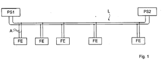
- FIG. 1 shows a power bus according to the prior art with two direct current sources PS1, PS2, which are electrically connected via a bus line L to a number of consumers (array elements FE ).
- the bus line L has branch lines A , which lead to the field elements FE. If an error occurs in such an arrangement, for example a short circuit, this affects the entire energy bus, so that none of the field elements FE can continue to be operated. Due to the large number of field elements FE, a high switch-on current also occurs.
- FIGS 2a, 2b show two variants of a power supply device SV1, SV1', each with a power bus that has a linear topology.
- the power bus includes a bus line L3, a first direct current source PS1 feeding in on one side, and a feed-in bus coupling element SBA1, by means of which current is fed into the bus line L3.
- In the bus line L3, there are interruption points U1...Un, US1...USm (here: m 1), at which n consumer bus coupling elements VBA1...VBAn and the feed bus coupling element SBA1 divide the bus line L3 into bus segments BS .
- the number s of bus segments depends on the number n of load bus coupling elements and the number m of feed bus coupling elements.
- the consumers FE1 ... FEn are each connected downstream of a consumer bus coupling element VBA1 ... VBAn.
- VBA1 ... VBAn at points of interruption U1 ... Un
- SBA1 ... SBAm at points of interruption US1 ... USm
- electrical isolation can be effected at the corresponding points of interruption (basic state or first operating state - please refer Figures 3a, 3b ; or disconnecting the feed, see 4 ).
- no consumer is connected downstream of the fourth consumer bus coupling element VBA4.
- Consumer bus coupling elements VBA4 without downstream consumer FE can serve as a reserve for consumers to be connected in the future.
- the first direct current source PS1 is only directly connected to the first consumer bus coupling element VBA1 and thus form the boundary of the energy bus (supply on one side).
- the first direct current source PS1 is arranged between two consumer bus coupling elements VBA2, VBA3.
- the power bus thus has a two-part linear topology.
- the feed bus coupling element SBA1 can operate the power bus on both sides here. This property is also used in the ring-shaped topologies described later.
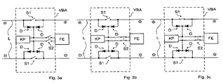
- a preferred structure of a consumer bus coupling element VBA installed in a bus line L is in Figures 3a, 3b and 3c shown.
- the consumer bus coupling element VBA includes switching elements S1, S2 , diodes D and a small processor KP.
- the diodes serve to connect the small processor KP and the consumer FE to the bus line L.
- the bus line L is interrupted via the switching elements S1, in other words it is segmented into bus segments.
- the switching elements S2 are used to switch on the consumer.
- the switching elements S1, S2 are preferably designed as relays or electronic switching elements.
- the consumer bus coupling element VBA has the following operating states: Im in Figure 3a In the basic state shown, the small processor KP is fed on one or both sides by the bus line L via the diodes. All switching elements S1 and S2 are open. in Figure 3b shown first operating state of the consumer FE is switched on by means of the second switching elements S2. After a time delay, the bus line is connected through to the first switching elements S1, as in FIG 3c shown (second operating state).
- the power supply device such as in Figure 2a shown, is operated in such a way that initially all consumer bus coupling elements VBA1 ... VBAn are in the basic state, so that the bus line L3 is electrically interrupted by each of the consumer bus coupling elements VBA1 ... VBAn.
- the direct current source PS1 By switching on the current of the direct current source PS1, only the consumer bus coupling element closest to the direct current source PS1 (first consumer bus coupling element VBA1) is initially supplied with current, so that the first consumer bus coupling element VBA1 itself and the consumer FE1 connected downstream of the first consumer bus coupling element VBA1 can be switched on.
- the functionality of the consumer bus coupling element VBA1 switches itself on when the supply SP1 is present.
- the consumer power supply is switched on by closing the second switching element S2.
- the consumer bus coupling element VBA1 is then in the first operating state. If these voltages are stable, then the electronics of the consumer FE1 switch on.
- the first consumer bus coupling element VBA1 is brought into the second operating state, i.e. the bus is switched through to the next (second) consumer bus coupling element VBA2 by means of the switching elements S1 , Which means that the next consumer bus coupling element (second consumer bus coupling element VBA2) is supplied with power, etc.
- Consumers FE1 ... FEn are therefore switched on one after the other, so that even when using a large number of consumers FE1 ... FEn only the low Starting current of a single consumer FE1 ... FEn occurs.
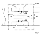
- FIG. 4 shows the basic form of the structure of a feed bus coupling element SBA , a direct current source PS being connected to the bus line L via the feed bus coupling element SBA.
- the feed-in coupling takes place here via diodes D1 .
- the diodes D1 can also be implemented as controlled switches.
- the diodes D2 are used to decouple the power supply of the small processor KP.
- Switching elements S3 and S4 are used to separate the potential-free supply PS from the bus line L. By staggering the connection using switching elements S3 and S4, two-part linear power buses, as in Figure 2b shown to be booted up sequentially.
- figure 5 shows a second variant of the power supply device SV2 .
- the power supply device SV1 shown has the energy bus of the power supply device SV2 in accordance with figure 5 a ring topology.
- the direct current source PS1 is connected via the feed bus coupling element SBA1 both to the first consumer bus coupling element VBA1 and to the nth consumer bus coupling element VBAn, so that current can be fed in on both sides.
- the bus line L1 is divided into n+m bus segments BS by the bus coupling elements SBA1, VBA1...VBAn.
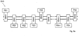
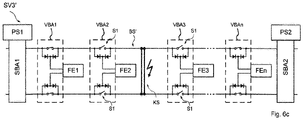
- FIG. 6a -c Another way of realizing a current feed on both sides is in Figure 6a -c shown.
- the power supply devices SV3, SV3' shown there include a power bus with a linear topology.
- Figure 6a is a variant SV3 with three direct current sources PS1, PS2, PS3.
- Figure 6b c an embodiment SV3' with two direct current sources PS1, PS2 is shown.
- each consumer bus coupling element VBA1 ... VBAn can be fed from two sides. The sequential start-up then preferably takes place starting from the two direct current sources PS1, PS2 simultaneously from both sides of the power bus.
- the first consumer bus coupling element VBA1 is connected to the first direct current source PS1 via the feed bus coupling element SBA1 and the nth consumer bus coupling element VBAn is connected to the further direct current source PS2 via a further feed bus coupling element SBA2.
- the relevant bus segment BS' can be isolated by bringing the adjacent load bus coupling elements (here: load bus coupling elements VBA2, VBA3) into the first operating state by opening the switching elements S1, as in Figure 6c shown. Consumers FE1, FE2 can then be supplied via the first direct current source PS1, consumers FE3 . . . FEn via the further direct current source PS2 (troubleshooting first stage).
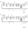
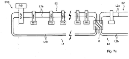
- FIG. 7a -c shows an embodiment of the power supply device SV4 according to the invention, in which a first energy bus B2 with a bus line L1 is electrically coupled with a second energy bus B2' with a bus line L2 by means of a bus coupling unit K.
- the bus lines L1, L2 are each divided by the bus coupling unit K into a main line section L1a, L2a, in which at least two load bus coupling elements VBA1, ..., VBA5 are arranged, and a return line section L1b, L2b, in which not necessarily load bus coupling elements are arranged, divided.
- Consumers FE1,..., FE5 are connected to the consumer bus coupling elements VBA1,...,VBA5.
- Both power buses B2, B2' have a ring-shaped topology figure 5 on.
- Figure 7b the case is shown that a segment of the main line section L1a was isolated due to a fault that had occurred (first-level fault rectification). Due to the coupling by means of the bus coupling unit K, the load bus coupling elements VBA1, ..., VBA5 and the loads FE1, ..., FE5 connected to them in the main line section L1a can also occur in the event of an error also occurring in the return line section L1b, as in Figure 7c shown, continue to be operated.
- the consumer bus coupling elements VBA4, VBA5 of the first power bus B2 that cannot be supplied via the first direct current source PS1 due to the error in the main line section L1a and return line section L1b are electrically connected to the second power bus B2' by means of the bus coupling unit K (troubleshooting second stage).
- FIG 8 1 shows an embodiment of the power supply device SV5 according to the invention, in which two energy buses B1 , B1' with a linear topology and two direct current sources PS1, PS2, PS1', PS2' are electrically coupled by means of the bus coupling unit K.
- the additional direct current source PS2 is arranged between the third consumer bus coupling element VBA3 and the fourth consumer bus coupling element VBA4 (i.e. directly electrically connected both to the third consumer bus coupling element VBA3 and to the fourth consumer bus coupling element VBA4), so that a feed into two directions.
- the second energy bus B1' includes two DC sources PS1', PS2' and three load bus coupling elements VBA1'...VBA3', to each of which a load FE1'...FE3' is connected.
- the consumer bus coupling elements VBA1 . . . VBA5, VBA1' due to the coupling by means of the bus coupling unit K, the consumer bus coupling elements VBA1 . . . VBA5, VBA1' .
- the consumer bus coupling elements VBA4, VBA5, VBA1' can be supplied with current from the current source PS2, PS2' of the respective other energy bus B1, B1' (first stage troubleshooting).
- This embodiment of the power supply device also handles other additional errors (troubleshooting of higher levels).
- the failure of the direct current source PS2 in the first energy bus B1 is described as an example. If the voltage is lost, diodes in the feed bus coupling element SBA2 (corresponding to the diodes D1 in the feed bus coupling element SBA in Fig.4 ) the voltage source PS2 from the bus line. The switching elements S3 and S4, controlled by the small processor KP (s. 4 ), remain closed. The load bus coupling elements VBA4 and VBA5 are thus supplied by the first direct current source PS1 even when the coupler K of the feed bus coupling element SBA2 is open.
- FIG. 9 1 shows an embodiment of the power supply device SV6 according to the invention, in which, for example, four energy buses with a linear topology and one direct current source each PS1, PS1′, PS1′′, PS1′′′ are electrically connected in a star configuration by the coupling unit K.
- Such a "star-shaped" coupling is generally possible with n energy buses, with n>2, it being possible for a star-shaped coupled power supply device to include both energy buses with a linear topology and with a ring-shaped topology.
- the coupling unit K must have a sufficient number of connections in accordance with the number and topology of the energy buses to be coupled.
- FIG. 10 shows an embodiment of the power supply device SV7 according to the invention, in which a power bus B1 with a linear topology (analogous to 2 ) with a power bus B2 with ring topology (analogue figure 5 ) is coupled by means of the bus coupling unit K.
- Both power buses B1, B2 each include a direct current source PS1, PS1'.
- Five consumer bus coupling elements VBA1, . . . , VBA5 are connected to the bus line L3 of the first energy bus B1.
- Four consumer bus coupling elements VBA1', ..., VBA4' are arranged in the second energy bus B2, where the consumer bus coupling element VBA4' is not located in the main line section L2a but in the return line section L2b of the bus line L2.
- First and second level error corrections are possible with this embodiment.
- the bus coupling unit K can assume all possible combinatorial positions (between the connections used).
- All of the embodiments include a segmented energy bus, with the segmentation being implemented by consumer bus coupling elements and feeder bus coupling elements, which can be brought from a basic state, in which the segments of the bus line adjoining the respective bus coupling element are electrically separated from one another, into a second operating state, in which these segments are electrically connected to each other.
- the switchable segmentation is a key feature for locating line faults (diagnostic function).
Landscapes
- Engineering & Computer Science (AREA)
- Power Engineering (AREA)
- Supply And Distribution Of Alternating Current (AREA)
- Direct Current Feeding And Distribution (AREA)
- Supplying Of Containers To The Packaging Station (AREA)
Priority Applications (12)
| Application Number | Priority Date | Filing Date | Title |
|---|---|---|---|
| ES18190273T ES2973513T3 (es) | 2016-05-18 | 2016-05-18 | Dispositivo de alimentación eléctrica y procedimiento para hacer funcionar un dispositivo de alimentación eléctrica |
| DK16170171.9T DK3247015T4 (da) | 2016-05-18 | 2016-05-18 | Strømforsyningsindretning og fremgangsmåde til drift af en strømforsyningsindretning |
| EP16170171.9A EP3247015B2 (de) | 2016-05-18 | 2016-05-18 | Stromversorgungseinrichtung und verfahren zum betreiben einer stromversorgungseinrichtung |
| FIEP16170171.9T FI3247015T4 (fi) | 2016-05-18 | 2016-05-18 | Virransyöttölaite ja menetelmä virransyöttölaitteen käyttämiseksi |
| FIEP18190273.5T FI3435508T3 (fi) | 2016-05-18 | 2016-05-18 | Virrantoimituslaitteisto ja menetelmä virrantoimituslaitteiston käyttämiseksi |
| DK18190273.5T DK3435508T3 (da) | 2016-05-18 | 2016-05-18 | Strømforsyningsindretning samt fremgangsmåde til drift af en strømforsyningsindretning |
| PT161701719T PT3247015T (pt) | 2016-05-18 | 2016-05-18 | Dispositivo de abastecimento de corrente e processo para a operação de um dispositivo de abastecimento de corrente |
| ES16170171T ES2767348T5 (es) | 2016-05-18 | 2016-05-18 | Dispositivo de alimentación eléctrica y procedimiento para hacer funcionar un dispositivo de alimentación eléctrica |
| PL18190273.5T PL3435508T3 (pl) | 2016-05-18 | 2016-05-18 | URZĄDZENIE ZASILAJĄCE i SPOSÓB DZIAŁANIA URZĄDZENIA ZASILAJĄCEGO |
| PL16170171.9T PL3247015T5 (pl) | 2016-05-18 | 2016-05-18 | Urządzenie zasilające oraz sposób pracy urządzenia zasilającego |
| EP18190273.5A EP3435508B1 (de) | 2016-05-18 | 2016-05-18 | Stromversorgungseinrichtung und verfahren zum betreiben einer stromversorgungseinrichtung |
| PT181902735T PT3435508T (pt) | 2016-05-18 | 2016-05-18 | Dispositivo de abastecimento de corrente e procedimento para operação de um dispositivo de abastecimento de corrente |
Applications Claiming Priority (1)
| Application Number | Priority Date | Filing Date | Title |
|---|---|---|---|
| EP16170171.9A EP3247015B2 (de) | 2016-05-18 | 2016-05-18 | Stromversorgungseinrichtung und verfahren zum betreiben einer stromversorgungseinrichtung |
Related Child Applications (2)
| Application Number | Title | Priority Date | Filing Date |
|---|---|---|---|
| EP18190273.5A Division-Into EP3435508B1 (de) | 2016-05-18 | 2016-05-18 | Stromversorgungseinrichtung und verfahren zum betreiben einer stromversorgungseinrichtung |
| EP18190273.5A Division EP3435508B1 (de) | 2016-05-18 | 2016-05-18 | Stromversorgungseinrichtung und verfahren zum betreiben einer stromversorgungseinrichtung |
Publications (3)
| Publication Number | Publication Date |
|---|---|
| EP3247015A1 EP3247015A1 (de) | 2017-11-22 |
| EP3247015B1 EP3247015B1 (de) | 2019-10-23 |
| EP3247015B2 true EP3247015B2 (de) | 2022-11-23 |
Family
ID=56083918
Family Applications (2)
| Application Number | Title | Priority Date | Filing Date |
|---|---|---|---|
| EP16170171.9A Active EP3247015B2 (de) | 2016-05-18 | 2016-05-18 | Stromversorgungseinrichtung und verfahren zum betreiben einer stromversorgungseinrichtung |
| EP18190273.5A Active EP3435508B1 (de) | 2016-05-18 | 2016-05-18 | Stromversorgungseinrichtung und verfahren zum betreiben einer stromversorgungseinrichtung |
Family Applications After (1)
| Application Number | Title | Priority Date | Filing Date |
|---|---|---|---|
| EP18190273.5A Active EP3435508B1 (de) | 2016-05-18 | 2016-05-18 | Stromversorgungseinrichtung und verfahren zum betreiben einer stromversorgungseinrichtung |
Country Status (6)
| Country | Link |
|---|---|
| EP (2) | EP3247015B2 (pl) |
| DK (2) | DK3247015T4 (pl) |
| ES (2) | ES2767348T5 (pl) |
| FI (2) | FI3247015T4 (pl) |
| PL (2) | PL3435508T3 (pl) |
| PT (2) | PT3247015T (pl) |
Families Citing this family (5)
| Publication number | Priority date | Publication date | Assignee | Title |
|---|---|---|---|---|
| PL3415399T3 (pl) | 2017-06-16 | 2020-04-30 | Siemens Mobility Ag | System do bezusterkowego zasilania elektrycznego urządzenia odbiorczego z redundantną magistralą energetyczną |
| EP3531137B1 (de) | 2018-02-26 | 2020-10-28 | Thales Management & Services Deutschland GmbH | Energieversorgungsvorrichtung und verfahren zum betreiben einer energieversorgungsvorrichtung |
| EP4037126B1 (de) * | 2021-01-29 | 2026-01-21 | Siemens Mobility AG | System zum kontrollierten schnellstart und betrieb eines zur ausfallsicheren versorgung eines elektrischen verbrauchers vorgesehenen redundant ausgeführten energiebusses |
| EP4160845B1 (de) * | 2021-09-29 | 2024-04-17 | Siemens Mobility AG | System zum kontrollierten starten und betreiben eines redundant ausgeführten energiebusses |
| DE102022206731A1 (de) | 2022-06-30 | 2024-01-04 | Gts Deutschland Gmbh | Schutzvorrichtung zum schutz einer elektrischen gleisfeld-infrastruktur, gleisfeld-energieversorgungseinrichtung und verfahren zur begrenzung von potentialverschiebungen in einer elektrischen gleisfeld-infrastruktur |
Citations (1)
| Publication number | Priority date | Publication date | Assignee | Title |
|---|---|---|---|---|
| WO2015000757A1 (de) † | 2013-07-02 | 2015-01-08 | Siemens Schweiz Ag | Einrichtung und verfahren zum betreiben von dezentral angeordneten funktionseinheiten |
Family Cites Families (5)
| Publication number | Priority date | Publication date | Assignee | Title |
|---|---|---|---|---|
| DE19819162B4 (de) | 1997-07-17 | 2008-01-10 | Siemens Ag | Schaltung zum Stellen und Überwachen von Weichen mit mehreren Antrieben |
| US5962929A (en) * | 1998-04-22 | 1999-10-05 | Lockheed Martin Corporation | Fault tolerant power distribution |
| DE102010030821A1 (de) * | 2010-07-01 | 2012-01-05 | Endress + Hauser Process Solutions Ag | Verfahren und Vorrichtung zur Inbetriebnahme von Feldgeräten, insbesondere von HART-Feldgeräten im Multidrop-Betriebsmodus |
| EP2549620A3 (de) | 2011-07-22 | 2013-04-24 | Siemens Schweiz AG | Einrichtung zur Betreiben von in einer industriellen Anlage angeordneten dezentralen Funktionseinheiten |
| DE102013225815A1 (de) | 2013-12-13 | 2015-06-18 | Db Netz Ag | Verfahren und Vorrichtung zum Betreiben einer unterbrechungsfreien Stromversorgung für Komponenten der Leit- und Sicherungstechnik |
-
2016
- 2016-05-18 PT PT161701719T patent/PT3247015T/pt unknown
- 2016-05-18 ES ES16170171T patent/ES2767348T5/es active Active
- 2016-05-18 EP EP16170171.9A patent/EP3247015B2/de active Active
- 2016-05-18 PL PL18190273.5T patent/PL3435508T3/pl unknown
- 2016-05-18 PL PL16170171.9T patent/PL3247015T5/pl unknown
- 2016-05-18 DK DK16170171.9T patent/DK3247015T4/da active
- 2016-05-18 ES ES18190273T patent/ES2973513T3/es active Active
- 2016-05-18 FI FIEP16170171.9T patent/FI3247015T4/fi active
- 2016-05-18 FI FIEP18190273.5T patent/FI3435508T3/fi active
- 2016-05-18 EP EP18190273.5A patent/EP3435508B1/de active Active
- 2016-05-18 PT PT181902735T patent/PT3435508T/pt unknown
- 2016-05-18 DK DK18190273.5T patent/DK3435508T3/da active
Patent Citations (1)
| Publication number | Priority date | Publication date | Assignee | Title |
|---|---|---|---|---|
| WO2015000757A1 (de) † | 2013-07-02 | 2015-01-08 | Siemens Schweiz Ag | Einrichtung und verfahren zum betreiben von dezentral angeordneten funktionseinheiten |
Also Published As
| Publication number | Publication date |
|---|---|
| FI3247015T4 (fi) | 2023-03-17 |
| DK3435508T3 (da) | 2024-03-11 |
| PT3435508T (pt) | 2024-02-29 |
| ES2767348T5 (es) | 2023-03-02 |
| EP3247015A1 (de) | 2017-11-22 |
| EP3247015B1 (de) | 2019-10-23 |
| PL3247015T3 (pl) | 2020-06-15 |
| DK3247015T3 (da) | 2020-01-27 |
| PL3435508T3 (pl) | 2024-05-06 |
| PL3247015T5 (pl) | 2023-03-27 |
| EP3435508A1 (de) | 2019-01-30 |
| EP3435508B1 (de) | 2024-01-10 |
| DK3247015T4 (da) | 2023-01-30 |
| PT3247015T (pt) | 2020-01-27 |
| ES2767348T3 (es) | 2020-06-17 |
| FI3435508T3 (fi) | 2024-03-14 |
| ES2973513T3 (es) | 2024-06-20 |
Similar Documents
| Publication | Publication Date | Title |
|---|---|---|
| EP3247015B2 (de) | Stromversorgungseinrichtung und verfahren zum betreiben einer stromversorgungseinrichtung | |
| EP2296244B1 (de) | Verfahren und Schaltungsanordnung zum Verbinden mindestens eines Strings einer Photovoltaikanlage mit einem Wechselrichter | |
| DE112011100833B4 (de) | Stromversorgungen für elektronische Einheiten | |
| EP3539192A1 (de) | Leistungsverteiler und bordnetz mit zumindest einem leistungsverteiler | |
| EP3837746B1 (de) | Elektrische ac/dc-umwandlungs-anordnung | |
| DE102015108372B4 (de) | Elektrische versorgungseinrichtung und damit ausgestattetes bordnetz eines fahrzeugs | |
| DE102015101235A1 (de) | Elektrisches Energieversorgungssystem für ein Fahrzeug und Verfahren zum Betreiben eines elektrischen Energieversorgungssystems | |
| EP3565074A1 (de) | Ankopplungsschaltung mit schaltender funktion zur ankopplung eines isolationsüberwachungsgerätes an ein ungeerdetes stromversorgungssystem | |
| EP3501100B1 (de) | Trennvorrichtung für einen photovoltaischen string | |
| EP2983286A1 (de) | Submodul für eine modulare Stromrichterschaltung | |
| EP3197726B1 (de) | Bordnetz | |
| EP2009522B1 (de) | Peripheriemodul und Peripheriesystem für ein Automatisierungssystem | |
| WO2002071600A2 (de) | Sicherheitsschaltvorrichtung | |
| DE102013221578A1 (de) | Elektronische Vorrichtung und Verfahren zum Betreiben einer elektronischen Vorrichtung | |
| DE102019203517B4 (de) | Verfahren zur Energieversorgung von Verbrauchern eines Bordnetzes für ein Fahrzeug, sowie ein Bordnetz für ein Fahrzeug | |
| WO2011033027A2 (de) | Schaltungsanordnung mit einem umrichterteil umfassend eine zentrale steuereinheit | |
| AT16035U1 (de) | Stromversorgungseinrichtung | |
| DE102009033604A1 (de) | Elektrische Netzanordnung zur Stromversorgung | |
| EP3391524B1 (de) | Konvertermodul für einen mehrstufenumrichter und verfahren zu dessen betrieb | |
| EP4010982B1 (de) | Elektronischer schutzschalter | |
| WO2023208603A1 (de) | Sicherungsschaltungsanordnung für ein energiesystem und energiesystem | |
| WO2024078860A1 (de) | Sicherungsvorrichtung für ein bordnetz eines fahrzeugs | |
| DE102019203518B4 (de) | 1Verfahren zur Energieversorgung von Verbrauchern eines Bordnetzes für ein Fahrzeug sowie ein Bordnetz für ein Fahrzeug | |
| EP3531137B1 (de) | Energieversorgungsvorrichtung und verfahren zum betreiben einer energieversorgungsvorrichtung | |
| EP2608343B1 (de) | Stromversorgung |
Legal Events
| Date | Code | Title | Description |
|---|---|---|---|
| PUAI | Public reference made under article 153(3) epc to a published international application that has entered the european phase |
Free format text: ORIGINAL CODE: 0009012 |
|
| STAA | Information on the status of an ep patent application or granted ep patent |
Free format text: STATUS: THE APPLICATION HAS BEEN PUBLISHED |
|
| AK | Designated contracting states |
Kind code of ref document: A1 Designated state(s): AL AT BE BG CH CY CZ DE DK EE ES FI FR GB GR HR HU IE IS IT LI LT LU LV MC MK MT NL NO PL PT RO RS SE SI SK SM TR |
|
| AX | Request for extension of the european patent |
Extension state: BA ME |
|
| RAP1 | Party data changed (applicant data changed or rights of an application transferred) |
Owner name: THALES MANAGEMENT & SERVICES DEUTSCHLAND GMBH |
|
| STAA | Information on the status of an ep patent application or granted ep patent |
Free format text: STATUS: REQUEST FOR EXAMINATION WAS MADE |
|
| 17P | Request for examination filed |
Effective date: 20180522 |
|
| RBV | Designated contracting states (corrected) |
Designated state(s): AL AT BE BG CH CY CZ DE DK EE ES FI FR GB GR HR HU IE IS IT LI LT LU LV MC MK MT NL NO PL PT RO RS SE SI SK SM TR |
|
| STAA | Information on the status of an ep patent application or granted ep patent |
Free format text: STATUS: EXAMINATION IS IN PROGRESS |
|
| 17Q | First examination report despatched |
Effective date: 20181129 |
|
| GRAP | Despatch of communication of intention to grant a patent |
Free format text: ORIGINAL CODE: EPIDOSNIGR1 |
|
| STAA | Information on the status of an ep patent application or granted ep patent |
Free format text: STATUS: GRANT OF PATENT IS INTENDED |
|
| INTG | Intention to grant announced |
Effective date: 20190603 |
|
| GRAS | Grant fee paid |
Free format text: ORIGINAL CODE: EPIDOSNIGR3 |
|
| GRAA | (expected) grant |
Free format text: ORIGINAL CODE: 0009210 |
|
| STAA | Information on the status of an ep patent application or granted ep patent |
Free format text: STATUS: THE PATENT HAS BEEN GRANTED |
|
| AK | Designated contracting states |
Kind code of ref document: B1 Designated state(s): AL AT BE BG CH CY CZ DE DK EE ES FI FR GB GR HR HU IE IS IT LI LT LU LV MC MK MT NL NO PL PT RO RS SE SI SK SM TR |
|
| REG | Reference to a national code |
Ref country code: GB Ref legal event code: FG4D Free format text: NOT ENGLISH |
|
| REG | Reference to a national code |
Ref country code: CH Ref legal event code: EP |
|
| REG | Reference to a national code |
Ref country code: IE Ref legal event code: FG4D Free format text: LANGUAGE OF EP DOCUMENT: GERMAN |
|
| REG | Reference to a national code |
Ref country code: DE Ref legal event code: R096 Ref document number: 502016007189 Country of ref document: DE |
|
| REG | Reference to a national code |
Ref country code: AT Ref legal event code: REF Ref document number: 1194745 Country of ref document: AT Kind code of ref document: T Effective date: 20191115 |
|
| REG | Reference to a national code |
Ref country code: RO Ref legal event code: EPE |
|
| REG | Reference to a national code |
Ref country code: CH Ref legal event code: NV Representative=s name: RIEDERER HASLER AND PARTNER PATENTANWAELTE AG, LI |
|
| REG | Reference to a national code |
Ref country code: FI Ref legal event code: FGE |
|
| REG | Reference to a national code |
Ref country code: DK Ref legal event code: T3 Effective date: 20200123 Ref country code: PT Ref legal event code: SC4A Ref document number: 3247015 Country of ref document: PT Date of ref document: 20200127 Kind code of ref document: T Free format text: AVAILABILITY OF NATIONAL TRANSLATION Effective date: 20200117 |
|
| REG | Reference to a national code |
Ref country code: SE Ref legal event code: TRGR |
|
| REG | Reference to a national code |
Ref country code: NL Ref legal event code: FP |
|
| REG | Reference to a national code |
Ref country code: NO Ref legal event code: T2 Effective date: 20191023 |
|
| REG | Reference to a national code |
Ref country code: LT Ref legal event code: MG4D |
|
| REG | Reference to a national code |
Ref country code: DE Ref legal event code: R026 Ref document number: 502016007189 Country of ref document: DE |
|
| PG25 | Lapsed in a contracting state [announced via postgrant information from national office to epo] |
Ref country code: LV Free format text: LAPSE BECAUSE OF FAILURE TO SUBMIT A TRANSLATION OF THE DESCRIPTION OR TO PAY THE FEE WITHIN THE PRESCRIBED TIME-LIMIT Effective date: 20191023 Ref country code: LT Free format text: LAPSE BECAUSE OF FAILURE TO SUBMIT A TRANSLATION OF THE DESCRIPTION OR TO PAY THE FEE WITHIN THE PRESCRIBED TIME-LIMIT Effective date: 20191023 Ref country code: GR Free format text: LAPSE BECAUSE OF FAILURE TO SUBMIT A TRANSLATION OF THE DESCRIPTION OR TO PAY THE FEE WITHIN THE PRESCRIBED TIME-LIMIT Effective date: 20200124 |
|
| PLBI | Opposition filed |
Free format text: ORIGINAL CODE: 0009260 |
|
| PG25 | Lapsed in a contracting state [announced via postgrant information from national office to epo] |
Ref country code: IS Free format text: LAPSE BECAUSE OF FAILURE TO SUBMIT A TRANSLATION OF THE DESCRIPTION OR TO PAY THE FEE WITHIN THE PRESCRIBED TIME-LIMIT Effective date: 20200224 Ref country code: HR Free format text: LAPSE BECAUSE OF FAILURE TO SUBMIT A TRANSLATION OF THE DESCRIPTION OR TO PAY THE FEE WITHIN THE PRESCRIBED TIME-LIMIT Effective date: 20191023 Ref country code: RS Free format text: LAPSE BECAUSE OF FAILURE TO SUBMIT A TRANSLATION OF THE DESCRIPTION OR TO PAY THE FEE WITHIN THE PRESCRIBED TIME-LIMIT Effective date: 20191023 |
|
| REG | Reference to a national code |
Ref country code: FI Ref legal event code: MDE Opponent name: SIEMENS MOBILITY AG |
|
| 26 | Opposition filed |
Opponent name: SIEMENS MOBILITY AG Effective date: 20200428 |
|
| REG | Reference to a national code |
Ref country code: ES Ref legal event code: FG2A Ref document number: 2767348 Country of ref document: ES Kind code of ref document: T3 Effective date: 20200617 |
|
| PG25 | Lapsed in a contracting state [announced via postgrant information from national office to epo] |
Ref country code: AL Free format text: LAPSE BECAUSE OF FAILURE TO SUBMIT A TRANSLATION OF THE DESCRIPTION OR TO PAY THE FEE WITHIN THE PRESCRIBED TIME-LIMIT Effective date: 20191023 |
|
| PG2D | Information on lapse in contracting state deleted |
Ref country code: IS |
|
| PG25 | Lapsed in a contracting state [announced via postgrant information from national office to epo] |
Ref country code: EE Free format text: LAPSE BECAUSE OF FAILURE TO SUBMIT A TRANSLATION OF THE DESCRIPTION OR TO PAY THE FEE WITHIN THE PRESCRIBED TIME-LIMIT Effective date: 20191023 Ref country code: CZ Free format text: LAPSE BECAUSE OF FAILURE TO SUBMIT A TRANSLATION OF THE DESCRIPTION OR TO PAY THE FEE WITHIN THE PRESCRIBED TIME-LIMIT Effective date: 20191023 Ref country code: IS Free format text: LAPSE BECAUSE OF FAILURE TO SUBMIT A TRANSLATION OF THE DESCRIPTION OR TO PAY THE FEE WITHIN THE PRESCRIBED TIME-LIMIT Effective date: 20200223 |
|
| PLAX | Notice of opposition and request to file observation + time limit sent |
Free format text: ORIGINAL CODE: EPIDOSNOBS2 |
|
| PG25 | Lapsed in a contracting state [announced via postgrant information from national office to epo] |
Ref country code: SM Free format text: LAPSE BECAUSE OF FAILURE TO SUBMIT A TRANSLATION OF THE DESCRIPTION OR TO PAY THE FEE WITHIN THE PRESCRIBED TIME-LIMIT Effective date: 20191023 Ref country code: SK Free format text: LAPSE BECAUSE OF FAILURE TO SUBMIT A TRANSLATION OF THE DESCRIPTION OR TO PAY THE FEE WITHIN THE PRESCRIBED TIME-LIMIT Effective date: 20191023 |
|
| PG25 | Lapsed in a contracting state [announced via postgrant information from national office to epo] |
Ref country code: SI Free format text: LAPSE BECAUSE OF FAILURE TO SUBMIT A TRANSLATION OF THE DESCRIPTION OR TO PAY THE FEE WITHIN THE PRESCRIBED TIME-LIMIT Effective date: 20191023 |
|
| PLBB | Reply of patent proprietor to notice(s) of opposition received |
Free format text: ORIGINAL CODE: EPIDOSNOBS3 |
|
| PG25 | Lapsed in a contracting state [announced via postgrant information from national office to epo] |
Ref country code: MC Free format text: LAPSE BECAUSE OF FAILURE TO SUBMIT A TRANSLATION OF THE DESCRIPTION OR TO PAY THE FEE WITHIN THE PRESCRIBED TIME-LIMIT Effective date: 20191023 |
|
| REG | Reference to a national code |
Ref country code: BE Ref legal event code: MM Effective date: 20200531 |
|
| PG25 | Lapsed in a contracting state [announced via postgrant information from national office to epo] |
Ref country code: LU Free format text: LAPSE BECAUSE OF NON-PAYMENT OF DUE FEES Effective date: 20200518 |
|
| PG25 | Lapsed in a contracting state [announced via postgrant information from national office to epo] |
Ref country code: IE Free format text: LAPSE BECAUSE OF NON-PAYMENT OF DUE FEES Effective date: 20200518 |
|
| PG25 | Lapsed in a contracting state [announced via postgrant information from national office to epo] |
Ref country code: BE Free format text: LAPSE BECAUSE OF NON-PAYMENT OF DUE FEES Effective date: 20200531 |
|
| REG | Reference to a national code |
Ref country code: FR Ref legal event code: PLFP Year of fee payment: 7 |
|
| PG25 | Lapsed in a contracting state [announced via postgrant information from national office to epo] |
Ref country code: TR Free format text: LAPSE BECAUSE OF FAILURE TO SUBMIT A TRANSLATION OF THE DESCRIPTION OR TO PAY THE FEE WITHIN THE PRESCRIBED TIME-LIMIT Effective date: 20191023 Ref country code: MT Free format text: LAPSE BECAUSE OF FAILURE TO SUBMIT A TRANSLATION OF THE DESCRIPTION OR TO PAY THE FEE WITHIN THE PRESCRIBED TIME-LIMIT Effective date: 20191023 Ref country code: CY Free format text: LAPSE BECAUSE OF FAILURE TO SUBMIT A TRANSLATION OF THE DESCRIPTION OR TO PAY THE FEE WITHIN THE PRESCRIBED TIME-LIMIT Effective date: 20191023 |
|
| PG25 | Lapsed in a contracting state [announced via postgrant information from national office to epo] |
Ref country code: MK Free format text: LAPSE BECAUSE OF FAILURE TO SUBMIT A TRANSLATION OF THE DESCRIPTION OR TO PAY THE FEE WITHIN THE PRESCRIBED TIME-LIMIT Effective date: 20191023 |
|
| PUAH | Patent maintained in amended form |
Free format text: ORIGINAL CODE: 0009272 |
|
| STAA | Information on the status of an ep patent application or granted ep patent |
Free format text: STATUS: PATENT MAINTAINED AS AMENDED |
|
| 27A | Patent maintained in amended form |
Effective date: 20221123 |
|
| AK | Designated contracting states |
Kind code of ref document: B2 Designated state(s): AL AT BE BG CH CY CZ DE DK EE ES FI FR GB GR HR HU IE IS IT LI LT LU LV MC MK MT NL NO PL PT RO RS SE SI SK SM TR |
|
| REG | Reference to a national code |
Ref country code: DE Ref legal event code: R102 Ref document number: 502016007189 Country of ref document: DE |
|
| REG | Reference to a national code |
Ref country code: DK Ref legal event code: T4 Effective date: 20230125 |
|
| REG | Reference to a national code |
Ref country code: SE Ref legal event code: RPEO |
|
| REG | Reference to a national code |
Ref country code: NL Ref legal event code: FP |
|
| REG | Reference to a national code |
Ref country code: ES Ref legal event code: DC2A Ref document number: 2767348 Country of ref document: ES Kind code of ref document: T5 Effective date: 20230302 |
|
| REG | Reference to a national code |
Ref country code: NO Ref legal event code: TB2 |
|
| REG | Reference to a national code |
Ref country code: CH Ref legal event code: PK Free format text: BERICHTIGUNGEN |
|
| RIN2 | Information on inventor provided after grant (corrected) |
Inventor name: NIEDERMAYER, KLAUS Inventor name: KOPF, DETLEF Inventor name: LAMPEL, MARTIN Inventor name: SCHWEHN, OLIVER Inventor name: STAEUBLE, ROLAND Inventor name: ZURFLUH, ERWIN |
|
| P01 | Opt-out of the competence of the unified patent court (upc) registered |
Free format text: CASE NUMBER: APP_35450/2024 Effective date: 20240613 |
|
| PGFP | Annual fee paid to national office [announced via postgrant information from national office to epo] |
Ref country code: NL Payment date: 20250425 Year of fee payment: 10 |
|
| PGFP | Annual fee paid to national office [announced via postgrant information from national office to epo] |
Ref country code: FI Payment date: 20250513 Year of fee payment: 10 |
|
| PGFP | Annual fee paid to national office [announced via postgrant information from national office to epo] |
Ref country code: PL Payment date: 20250428 Year of fee payment: 10 Ref country code: DE Payment date: 20250423 Year of fee payment: 10 |
|
| PGFP | Annual fee paid to national office [announced via postgrant information from national office to epo] |
Ref country code: ES Payment date: 20250603 Year of fee payment: 10 Ref country code: GB Payment date: 20250417 Year of fee payment: 10 Ref country code: DK Payment date: 20250516 Year of fee payment: 10 |
|
| PGFP | Annual fee paid to national office [announced via postgrant information from national office to epo] |
Ref country code: NO Payment date: 20250509 Year of fee payment: 10 |
|
| PGFP | Annual fee paid to national office [announced via postgrant information from national office to epo] |
Ref country code: IT Payment date: 20250428 Year of fee payment: 10 |
|
| PGFP | Annual fee paid to national office [announced via postgrant information from national office to epo] |
Ref country code: PT Payment date: 20250516 Year of fee payment: 10 |
|
| PGFP | Annual fee paid to national office [announced via postgrant information from national office to epo] |
Ref country code: FR Payment date: 20250422 Year of fee payment: 10 |
|
| PGFP | Annual fee paid to national office [announced via postgrant information from national office to epo] |
Ref country code: BG Payment date: 20250429 Year of fee payment: 10 |
|
| PGFP | Annual fee paid to national office [announced via postgrant information from national office to epo] |
Ref country code: CH Payment date: 20250601 Year of fee payment: 10 |
|
| PGFP | Annual fee paid to national office [announced via postgrant information from national office to epo] |
Ref country code: RO Payment date: 20250508 Year of fee payment: 10 Ref country code: AT Payment date: 20250425 Year of fee payment: 10 |
|
| PGFP | Annual fee paid to national office [announced via postgrant information from national office to epo] |
Ref country code: SE Payment date: 20250429 Year of fee payment: 10 |