EP3247006A1 - Contact arrangement for a rotational bearing - Google Patents
Contact arrangement for a rotational bearing Download PDFInfo
- Publication number
- EP3247006A1 EP3247006A1 EP16169937.6A EP16169937A EP3247006A1 EP 3247006 A1 EP3247006 A1 EP 3247006A1 EP 16169937 A EP16169937 A EP 16169937A EP 3247006 A1 EP3247006 A1 EP 3247006A1
- Authority
- EP
- European Patent Office
- Prior art keywords
- bearing
- contact
- elements
- rotational
- sliding contact
- Prior art date
- Legal status (The legal status is an assumption and is not a legal conclusion. Google has not performed a legal analysis and makes no representation as to the accuracy of the status listed.)
- Granted
Links
- 238000004804 winding Methods 0.000 claims abstract description 66
- 238000000034 method Methods 0.000 claims abstract description 14
- 239000004020 conductor Substances 0.000 claims abstract description 4
- 229910000831 Steel Inorganic materials 0.000 claims description 5
- 239000010959 steel Substances 0.000 claims description 5
- RYGMFSIKBFXOCR-UHFFFAOYSA-N Copper Chemical compound [Cu] RYGMFSIKBFXOCR-UHFFFAOYSA-N 0.000 claims description 4
- 239000000956 alloy Substances 0.000 claims description 4
- 239000010949 copper Substances 0.000 claims description 4
- 229910052802 copper Inorganic materials 0.000 claims description 4
- 229910052709 silver Inorganic materials 0.000 claims description 4
- 239000004332 silver Substances 0.000 claims description 4
- 229910001369 Brass Inorganic materials 0.000 claims description 3
- 229910045601 alloy Inorganic materials 0.000 claims description 3
- 239000010951 brass Substances 0.000 claims description 3
- 230000008878 coupling Effects 0.000 claims description 3
- 238000010168 coupling process Methods 0.000 claims description 3
- 238000005859 coupling reaction Methods 0.000 claims description 3
- 239000000463 material Substances 0.000 description 6
- 230000002349 favourable effect Effects 0.000 description 5
- 230000001965 increasing effect Effects 0.000 description 5
- OKTJSMMVPCPJKN-UHFFFAOYSA-N Carbon Chemical compound [C] OKTJSMMVPCPJKN-UHFFFAOYSA-N 0.000 description 3
- 230000015572 biosynthetic process Effects 0.000 description 3
- 229910002804 graphite Inorganic materials 0.000 description 3
- 239000010439 graphite Substances 0.000 description 3
- 238000005096 rolling process Methods 0.000 description 3
- XEEYBQQBJWHFJM-UHFFFAOYSA-N Iron Chemical compound [Fe] XEEYBQQBJWHFJM-UHFFFAOYSA-N 0.000 description 2
- 230000001419 dependent effect Effects 0.000 description 2
- 230000010363 phase shift Effects 0.000 description 2
- 206010063493 Premature ageing Diseases 0.000 description 1
- 208000032038 Premature aging Diseases 0.000 description 1
- BQCADISMDOOEFD-UHFFFAOYSA-N Silver Chemical compound [Ag] BQCADISMDOOEFD-UHFFFAOYSA-N 0.000 description 1
- 230000007423 decrease Effects 0.000 description 1
- 230000003247 decreasing effect Effects 0.000 description 1
- 238000009760 electrical discharge machining Methods 0.000 description 1
- 239000012530 fluid Substances 0.000 description 1
- 230000001939 inductive effect Effects 0.000 description 1
- 150000002505 iron Chemical class 0.000 description 1
- 229910052742 iron Inorganic materials 0.000 description 1
- 230000001050 lubricating effect Effects 0.000 description 1
- 239000000696 magnetic material Substances 0.000 description 1
- 239000002184 metal Substances 0.000 description 1
- 229910052751 metal Inorganic materials 0.000 description 1
- 150000002739 metals Chemical class 0.000 description 1
- 239000000203 mixture Substances 0.000 description 1
- 230000010355 oscillation Effects 0.000 description 1
- 230000002028 premature Effects 0.000 description 1
- 238000004381 surface treatment Methods 0.000 description 1
Images


Classifications
-
- H—ELECTRICITY
- H01—ELECTRIC ELEMENTS
- H01R—ELECTRICALLY-CONDUCTIVE CONNECTIONS; STRUCTURAL ASSOCIATIONS OF A PLURALITY OF MUTUALLY-INSULATED ELECTRICAL CONNECTING ELEMENTS; COUPLING DEVICES; CURRENT COLLECTORS
- H01R39/00—Rotary current collectors, distributors or interrupters
- H01R39/02—Details for dynamo electric machines
- H01R39/08—Slip-rings
- H01R39/12—Slip-rings using bearing or shaft surface as contact surface
-
- H—ELECTRICITY
- H01—ELECTRIC ELEMENTS
- H01R—ELECTRICALLY-CONDUCTIVE CONNECTIONS; STRUCTURAL ASSOCIATIONS OF A PLURALITY OF MUTUALLY-INSULATED ELECTRICAL CONNECTING ELEMENTS; COUPLING DEVICES; CURRENT COLLECTORS
- H01R39/00—Rotary current collectors, distributors or interrupters
- H01R39/02—Details for dynamo electric machines
- H01R39/46—Auxiliary means for improving current transfer, or for reducing or preventing sparking or arcing
- H01R39/54—Auxiliary means for improving current transfer, or for reducing or preventing sparking or arcing by use of impedance between brushes or segments
-
- F—MECHANICAL ENGINEERING; LIGHTING; HEATING; WEAPONS; BLASTING
- F03—MACHINES OR ENGINES FOR LIQUIDS; WIND, SPRING, OR WEIGHT MOTORS; PRODUCING MECHANICAL POWER OR A REACTIVE PROPULSIVE THRUST, NOT OTHERWISE PROVIDED FOR
- F03D—WIND MOTORS
- F03D80/00—Details, components or accessories not provided for in groups F03D1/00 - F03D17/00
- F03D80/70—Bearing or lubricating arrangements
-
- F—MECHANICAL ENGINEERING; LIGHTING; HEATING; WEAPONS; BLASTING
- F05—INDEXING SCHEMES RELATING TO ENGINES OR PUMPS IN VARIOUS SUBCLASSES OF CLASSES F01-F04
- F05B—INDEXING SCHEME RELATING TO WIND, SPRING, WEIGHT, INERTIA OR LIKE MOTORS, TO MACHINES OR ENGINES FOR LIQUIDS COVERED BY SUBCLASSES F03B, F03D AND F03G
- F05B2240/00—Components
- F05B2240/50—Bearings
-
- H—ELECTRICITY
- H01—ELECTRIC ELEMENTS
- H01R—ELECTRICALLY-CONDUCTIVE CONNECTIONS; STRUCTURAL ASSOCIATIONS OF A PLURALITY OF MUTUALLY-INSULATED ELECTRICAL CONNECTING ELEMENTS; COUPLING DEVICES; CURRENT COLLECTORS
- H01R2201/00—Connectors or connections adapted for particular applications
- H01R2201/10—Connectors or connections adapted for particular applications for dynamoelectric machines
Definitions
- the contact holder can generally be U-shaped. This shape is advantageous to allow the formation of a loop of the secondary winding of the above-mentioned transformer.
- U-shaped contact holder can comprise two arms, which can be at least long enough to bridge a radial gap between the two bearing elements of the rotational bearing.
- the secondary winding of the transformer can have exactly one loop, which is then the loop provided by the contact holder, the two sliding contact elements and the part of the surface of the second bearing element between the two contact elements, as described above.
- the secondary winding can have more loops in addition to this first loop.
- a single loop can be preferred however, in order to achieve a small inductance in the secondary winding and therefore to keep the impedance low for high-frequency shunt currents.
- the sliding contact elements can in particular be brush contact elements. Suitable materials for such brush contact elements are for example copper, brass, steel, silver or an alloy - particularly including one of these metals - or graphite.
- the sliding contact elements can be disposed such that the resistance across the contact element and between the two bearing elements falls with increasing current, particularly in the current range between 10mA and 10 A or in the current densities range between 0.02mA/mm 2 and 20mA/mm 2 .
Landscapes
- Sliding-Contact Bearings (AREA)
Abstract
- a contact holder (9) mountable on a first one of the two bearing elements (5a),
- at least two sliding contact elements (11a,11b) mounted on the contact holder (9),
wherein each sliding contact element (11a,11b) is suitable for forming a sliding contact with a part of a surface (13a,13b) of the second one of the two bearing elements (5b), wherein the contact holder (9) and the sliding contact elements (11a, 11b) are disposed such that a secondary winding (15) is formed with at least one winding loop (15) extending along a first sliding contact element (11a), the contact holder (9), the second contact element (11b) and a part of the surface (13c) of the second bearing element (5b), provided that the surface is formed of an electrically conductive material.
Description
- The invention relates to a contact arrangement, in particular a contact arrangement based on slip rings, for electrically contacting an inner and an outer bearing element of a rotational bearing, in particular a rotational bearing for a wind turbine. The invention further relates to a rotational bearing with such a contact arrangement, to a wind turbine generator with such a rotational bearing and to a method for operating such a rotational bearing.
- Many applications require rotational bearings for allowing a coaxial rotation between two elements. Within the bearing, the rotation motion can take place between two bearing elements, which are referred to as inner and outer bearing elements (or more specifically: bearing shells) according to their radial position. In many applications it is important to suppress electrical discharges between the inner and outer bearing elements, in particular if these elements are made of or at least contain electrically conductive materials.
- One important application for such rotational bearings is for the connection of rotating and stationary parts in a wind turbine. A wind turbine comprises one or more rotor blades. The rotor blades are connected to a hub. The rotor blades and the hub form the rotor of a wind turbine. The wind interacts with the rotor and causes a rotation of the rotor. The rotation of the rotor is transferred to an electrical generator, either directly or via a gearing to increase the rotational speed. The rotational energy of the rotor is then converted into electrical energy.
- The rotation of the rotor is often transferred over a shaft. The rotor, the shaft and the rotor of the generator are rotatable in respect to the stationary part of the wind turbine. The hub, and in cases the shaft, need to be connected to the stationary part of the wind turbine by a rotational bearing.
- Known rotational bearings for wind turbines are often built as ball bearings or roller bearings. One problem during the operation of a wind turbine is that voltages can build up between the inner and outer bearing elements, for example between inner and outer bearing shells or inner and outer bearing rings. Such voltages can lead to electrical discharges, which can then lead to a damage of the rotational bearing, for example by the mechanism of electrical discharge machining. In particular, punctual breakthroughs between a ball or roller and the surface on which it moves (sometimes referred to as a racetrack) can significantly accelerate wearing of the rotational bearing. To protect rotational bearings of such premature wear by electrical discharge, it has been known to introduce a permanent current path in parallel to the inner and outer bearing elements, in other words a shunt. Such a shunt can be formed by adding an electrical connection element, typically in the form of a sliding contact element, for example a brush contact. Such a sliding contact element can provide an electrical connection between an electrically conductive outer bearing element and an electrically conductive inner bearing element for all relative rotational positions of the bearing. This measure can significantly reduce the risk of electrical discharges across the bearing.
- It has turned out that the resistance of a sliding contact can be a strong function of the current going through the contact. The resistance is typically much higher in the low-current range than in the high-current range. For example, for a brush made of graphite, copper, silver, steel or an alloy material slipping on a ring of above mentioned materials (in which usually different materials of brush and slip are combined) shunting two bearing elements made of high tensile steel, the resistance can be ten times higher at brush current densities of < 0.3mA/mm2 than at brush current densities of > 3mA/mm2.
- It should be mentioned that in general, one of the surfaces of a bearing element can act as a slip ring directly, especially through a polished surface. This surface can then get in contact with the brush. Alternatively, a slip ring of a different material and/or a specially treated ring mounted on the bearing shell can be used for establishing the contact.
- Due to the dependence of the resistance on the current, the resistance of such a brush contact shunt can sometimes be too high to reduce the build-up of a voltage across the bearing, and a direct electrical discharge between inner and outer bearing element can sometimes not be prevented. This is particularly the case, when the brushes carry low currents, and this situation often arises in the brush connections used to shunt the rotational bearings in wind power turbines.
- It is therefore a goal of the present invention to provide a contact arrangement for a rotational bearing, in which the resistance of the electrical contact between inner and outer bearing element is reduced. A further goal of the invention is to provide a rotational bearing with such an improved contact arrangement and a method for operating such a rotational bearing.
- These objects of the invention are achieved by claim 1 with respect to the contact arrangement, by
claim 7 with respect to the rotational bearing and by claim 14 with respect to the method. - The contact arrangement according to the invention is configured for electrically contacting an inner and an outer bearing element of a rotational bearing allowing a coaxial rotation between the inner and outer bearing elements. The contact arrangement comprises a contact holder mountable on a first one of the two bearing elements and at least two sliding contact elements mounted on the contact holder. Each sliding contact element is suitable for forming a sliding contact with a part of the surface of the second one of the two bearing elements. The contact holder and the sliding contact elements are disposed such that a secondary winding of a transformer is formed with at least one winding loop extending along a first sliding contact element, the contact holder, the second contact element and a part of the surface of the second bearing element, provided that at least the surface is formed of an electrically conductive material. The contact arrangement further comprises a primary winding with at least one winding loop, wherein the primary and secondary windings are disposed to form a transformer.
- In other words, an electrically conductive loop can be formed between the contact holder, the two sliding contact elements and that part of the surface of the second bearing element, which is located between the two sliding contact elements. In order to allow the formation of such an electrically conductive loop, the sliding contact elements, the contact holder and the surface of the second bearing element should be electrically conductive. In this context, it is to be understood that the mentioned surface of the second one of the two bearing elements can also be the surface of an additionally mounted specific sliding ring, which can for example be of a different material and/or have been subject to a different surface treatment than the bulk of this bearing element.
- If the bearing elements of the rotational bearing are rotated with respect to each other, the sliding contact elements slide along the surface of the second bearing element and contact different positions of this surface for each rotational position. Therefore, for each such rotational position, the part of the surface located between the two sliding contact elements will be different. But for each rotational position, an electrically conductive loop will still be formed across the contact holder, the two sliding contact elements and the part of the surface of the second bearing element between them. Due to the formation of this electrically conductive loop the mentioned components can act together to form the secondary winding of a transformer. This secondary winding can comprise further winding loops in addition to the one winding loop just described, however only the one above-mentioned loop is sufficient for acting as a secondary transformer winding. The other (primary) transformer winding is integrated within the contact element, and the two windings are configured such that they can interact with each other to form an overall transformer. In other words, the primary and secondary windings are inductively coupled, such that an alternating current applied at the primary winding can induce an alternating current at the secondary winding. Due to this configuration, the resistance between the two bearing elements across the two sliding contact elements can be modified by applying current at the primary winding, which leads to an alternating current flow across the secondary winding. In particular, the induced flow of alternating current in the secondary winding can lead to a decreased resistance of the sliding contact elements in the electrical path between the two bearing elements. This is generally the case if the resistance-current characteristic is such that the resistance across the sliding contact element decreases with increased current. In this case, the functionality of the sliding contact elements for preventing electric discharges between the two bearing elements of the rotational bearing can be improved by feeding an alternating current into the primary winding of the transformer.
- The above-mentioned surface of the second bearing element, along which the sliding contact elements can slide, can generally be a ring-shaped surface. In particular, the surface can be an inner our outer cylindrical surface with circular cross section. Alternatively, the surface can also be a ring-shaped side surface of a bearing element with circular cross section. In general, it is important that the (at least) two sliding contact elements are configured such that they can slide along the circumference of such a surface, which maintaining electrical contact between the two bearing elements through both sliding contact elements for all rotational positions of the bearing. In order to achieve this, the contact holder should also be mounted so as to be in electrical contact with an electrically conducting surface of the first bearing element. When this is the case, the two bearing elements are shunted via both sliding contact elements, and the feeding of alternating current into the transformer reduces the resistance of both these parallel shunts.
- The rotational bearing according to the invention comprises an inner bearing element and an outer bearing element, wherein the rotational bearing is disposed to allow a coaxial rotation between the inner and outer bearing elements. The bearing further comprises at least one contact element according to the present invention, wherein the contact holder is mounted on a first one of the two bearing elements and wherein the sliding contact elements are each arranged to form a sliding contact with part of a surface of the second one of the two bearing elements. The advantages of this rotational bearing are analogous to the above-mentioned advantages of the contact arrangement.
- A wind turbine according to the present invention comprises at least one rotational bearing according to the present invention. The advantages of this wind turbine are also analogous to the advantages of the contact arrangement and the rotational bearing.
- The method according to the present invention is a method for operating the above-mentioned rotational bearing. The method comprises the step of providing an alternating current to the primary winding of the at least one contact arrangement. The advantageous of the method also follow from the above-mentioned advantages of the rotational bearing.
- Advantageous configurations and embodiments of the method according to the invention follow from the claims dependent on claim 1,
claim 7, claim 13 and claim 14 as well as the following description. The advantageous features of the contact arrangement, the rotational bearing, the wind turbine and the method can generally be combined. - The contact holder can generally be U-shaped. This shape is advantageous to allow the formation of a loop of the secondary winding of the above-mentioned transformer. In particular, U-shaped contact holder can comprise two arms, which can be at least long enough to bridge a radial gap between the two bearing elements of the rotational bearing.
- Irrespective of whether the contact holder is U-shaped or not, it can generally be of a mirror symmetric shape, where each of two symmetric sides is connected to one of the sliding contact elements.
- The contact arrangement can further comprise a transformer core suitable for inductively coupling the primary winding and the secondary winding of the transformer. Advantageously, this transformer core can comprise or even consist of a soft magnetic material, in particular iron.
- The transformer core can advantageously comprise a stack of laminated electrically conducting sheets. Irrespective of its composition, the transformer core can advantageously be E-shaped or 8-shaped and/or comprise an E-shaped part.
- The contact arrangement can further comprise an alternating current source which is configured to provide an alternating current (AC) to the primary winding of the transformer. In particular, this current source can be configured to deliver alternating current at a voltage at or below 1V and a current of at least 1 A, in particular at least 10 A. The advantage of operating the transformer in this low-voltage, high-current regime is that a high current can also be induced in the secondary winding, and then the resistance across the sliding contact elements can be more significantly reduced than by a lower-current operation. Particularly, the alternating current source and the primary and secondary windings of the transformer can be configured that an alternating current of at least 1 A, more favorably at least 10 A, can be fed into the secondary winding of the transformer.
- The current source can for example be configured to provide an alternating current of a frequency in the range of about 50 Hz or about 60 Hz. However, the frequency can also be higher or lower than these two examples, a suitable frequency range is for example between 1 Hz and 10 MHz, particularly favorably between 10 Hz and 100 kHz.
- The secondary winding of the transformer can have exactly one loop, which is then the loop provided by the contact holder, the two sliding contact elements and the part of the surface of the second bearing element between the two contact elements, as described above. Optionally, the secondary winding can have more loops in addition to this first loop. A single loop can be preferred however, in order to achieve a small inductance in the secondary winding and therefore to keep the impedance low for high-frequency shunt currents.
- The primary winding of the transformer can have one or more loops, in particular the number of loops can favorably be in the range between 1 and 1000, most favorably between 10 and 1000. The ratio of number of loops in the primary winding versus the number of loops in the secondary winding can favorable be below 1000.
- The sliding contact elements can in particular be brush contact elements. Suitable materials for such brush contact elements are for example copper, brass, steel, silver or an alloy - particularly including one of these metals - or graphite. In general and favorably, the sliding contact elements can be disposed such that the resistance across the contact element and between the two bearing elements falls with increasing current, particularly in the current range between 10mA and 10 A or in the current densities range between 0.02mA/mm2 and 20mA/mm2.
- In general, the resistance of each sliding contact element along its direction of current transport between the two bearing elements can be favorably below 0.5 Ohm. With a resistance in the range the build-up of voltages that are high enough to lead to damage due to electrical discharge can favorably be prevented.
- The cross section with respect to this direction of current transport can be favorably between 200 mm2 and 2000 m2 - particularly about 500 mm2 - for each brush. The cross section can be favorably above 200 mm2, because then the sliding contact elements are better suited to withstand occasional high lighting currents. The cross section can be favorably below 2000 mm2, because then the current density during normal operation of the contact arrangement can be high enough to allow a sufficiently low shunt resistance for suppressing electrical discharges between the bearing elements.
- In the rotational bearing according to the invention, the first bearing element can for example be the outer bearing element and the second bearing element can be the inner bearing element of the rotational bearing. In other words, the contact holder with the at least two sliding contact elements can be mounted to the outer bearing element and the sliding contacts can then slide on a surface of the inner bearing element. Alternatively, the first bearing element can be the inner bearing element and the second bearing element can be the outer bearing element.
- Independent of which bearing element is the first or second bearing element, one or both of the two bearing elements can be a bearing shell and/or a bearing ring.
- In general the rotational bearing can be a rolling-element bearing, in particular of the type of a ball bearing or roller bearing. In this type of bearing, the rolling elements - in particular balls or cylindrical rollers - can be distributed over the circumference of the bearing and can be radially positioned between the inner and outer bearing elements. The shape of these rolling elements then helps to reduce the friction between inner and outer bearing elements during the rotational motion. Alternatively or in addition to these rolling elements, the rotational bearing can comprise a lubricating fluid between the inner and outer bearing elements. Alternatively, the bearing can also be a magnetic bearing.
- The rotational bearing can comprise a plurality of contact arrangements according to the present invention. These contact arrangements can then be distributed across a circumference of the rotational bearing. For example, in the general case of ring-shaped first and second bearing elements, the contact arrangements can be mounted via their contact holders on a circumference of a ring-shaped surface of the first bearing element, and the sliding contacts can be brought into electrical contact with a ring-shaped surface of the second bearing element, at different circumferential positions, according to the position of each contact arrangement along the perimeter of the first bearing element and according to the respective angular position of the two bearing elements at each moment.
- Such a plurality of contact arrangement can lead to a particularly favorable configuration, where a plurality of pairs of parallel shunt paths is provided between the two bearing elements, thus reliably preventing electrical discharges between them. All the sliding contact elements of the plurality of contact arrangements are connected in parallel by the two bearing elements, which are in electrical contact with each.
- In the embodiments with a plurality of contact arrangements in the bearing, the bearing can in principle comprise only one alternating current source, which can be used to feed the primary windings of all the contact arrangements. This configuration is very simple, because few electrical components are required in order to reliably prevent electrical discharges.
- In another preferred configuration, the bearing can also comprise several alternating current sources. In particular, there can be at least three current sources, and these current sources can be used to feed three or more contact arrangements. In particular the number of contact arrangements can then be three or a multiple of three. In this type of embodiment, the multiple current sources can be configured to provide alternating currents to the primary windings of the multiple contact arrangements, which providing a phase shift between the different alternating currents at each contact arrangement or group of contact arrangements. The respective relative phase shift between each (group of) contact arrangement(s) can in particular be 120°. This configuration is particularly favorable for providing at least one reliable shunt path with low resistance at any given time. This is because at a given time, when in one contact arrangement there is a zero crossing of the alternating current, which leads to a high resistance in the respective sliding contact at this moment, at least one other contact arrangement is not in such a zero-crossing state, but instead has a high current and consequently a low resistance at that moment.
- A similar advantage can be achieved by providing several alternating current sources which can drive the primary windings of the plurality of contact arrangements at different frequencies. In this case, the different frequencies also lead to situations, where usually in at least one (and usually more) of the contact arrangements there is a state with a significant amount of current and therefore significantly lowered shunt resistance, compared to a state with zero current.
- Therefore, the embodiments with several contact arrangements driven by several current sources with differing operating conditions provide a safety mechanism, where usually at least one contact arrangement provides a low resistivity shunt path between the two bearing elements of the bearing.
- In general, the resistance across the sliding contact elements can also be frequency dependent, and a frequency range which provides a comparatively low resistance can favorably be selected.
- The rotational bearing can favorably be a rotational bearing for a wind turbine. Accordingly, a wind turbine with such a bearing is also claimed. In wind turbines, it is particularly important to use rotational bearings, where electrical discharges between the bearing elements are suppressed and a premature aging of the bearing due to such discharges is prevented.
- The method for operating the rotational bearing according to the invention, the bearing can favorably be of the type comprising a plurality of contact arrangements, as described above. Then, also the method can comprise the step of providing an alternating current to each of the primary windings of the plurality of contact arrangements, where each contact arrangement is driven with a current of different phase and/or different frequency.
- Further advantages and details of the invention may be found in the exemplary embodiments described below and in the drawings, in which:
- Fig. 1
- shows a schematic representation of the dependency of the resistance across a single sliding contact element as a function of current density,
- Fig. 2
- shows a schematic perspective view of a rotational bearing according to an embodiment of the invention,
- Fig. 3
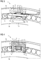
- shows a detailed view of a contact arrangement within the rotational bearing of
Fig. 2 , - Fig. 4
- shows a sectional view of the contact arrangement of
Fig. 3 , - Fig. 5
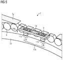
- shows a different sectional view of the contact arrangement of
Fig. 3 . -
Fig. 1 shows a schematic representation of the dependency of the resistance across a single sliding contact element as a function of current density. The sliding contact element can be a contact element between two bearing elements of a rotational bearing according to the state of the art. However, the sliding contact element can also be one of the two sliding contact elements in a contact arrangement according to the present invention. - As can be seen from the resistance-current characteristic 1 shown in
Fig. 1 , the resistance is a falling function of increasing currents and therefore also current density for a given geometry and dimensions of the sliding contact element. The resistance-current characteristic 1 is non-linear in the sense that the slope of the curve is even stronger for lower currents. The dependence shown inFig. 1 is only a very schematic representation, but it is typical for many types of sliding contact elements of different materials. For example, such contact elements can be made of or comprise copper, brass, steel, silver, alloy, graphite. It has been observed and it is favorable in the context of the current invention that the resistance can be lowered by at least a factor of ten by increasing the current density in the sliding contact element from 0.2mA/mm2 to 2mA/mm2. From the dependency shown inFig. 1 it can be seen that it can be favorable to operate such a sliding contact element at higher average currents, for example at average currents above 1A, because then the average resistance is significantly lower than at lower average currents. -
Fig. 2 shows a schematic perspective view of a rotational bearing according to an embodiment of the invention. This rotational bearing is a bearing for the connection of rotating and stationary parts in a wind turbine. The bearing comprises anouter bearing element 5a and aninner bearing element 5b which can rotate relative to each other with respect to a rotational axis A. For example, within the wind turbine, theouter bearing element 5b can be the rotating element and can be attached to other rotating parts, and the inner bearing element can be the stationary element and can be attached to other stationary parts. However, theouter bearing element 5b can in principle also be the stationary element and theinner bearing element 5a can be the outer bearing element. - In the example of
Fig. 2 , the inner and outer bearing elements are shown as circular rings. However, the structures of these bearingelements inner surface 25a of theouter bearing element 5a is in relatively close proximity to and can rotate against anouter surface 25b of theinner bearing element 5b. The axis of relative rotation A is then also a symmetry axis of each of thecylindrical surfaces - The rotational bearing of
Fig. 2 comprises threecontact arrangements 7, each of a same or similar configuration and according to the present invention. The configuration of one of these contact arrangements is shown in more detail in perspective schematic view inFig. 3 . - As
Fig. 3 shows, thecontact arrangement 7 comprises a U-shaped contact holder which is mounted on the first and in this caseouter bearing element 5a. Thefirst bearing element 5a and thecontact holder 9 are both electrically conductive and the mounting of thecontact holder 9 provides an electrically conductive connection betweenfirst bearing element 5a and contact holder. In the example ofFig. 3 , thecontact holder 9 has a central part which extends essentially along the local direction of the circumference of thefirst bearing element 5a, and it has two arms which extend essentially radially inwards, towards the second and in this caseinner bearing element 5b. Two slidingcontact elements inner bearing element 5b. Each slidingcontact element respective part part 13c of the inner bearing element which extends between these two contactedsurface parts - Due to the configuration of the
contact holder 9, slidingcontact elements second bearing element 5b, a circular current can flow in a loop through these parts, as denoted by I1 inFig. 3 . This circular current path I1 can act as a current path of a winding of a transformer, in this case it is regarded as the secondary winding 15 of a transformer, and the primary winding 17 is also provided as a separate part of thecontact arrangement 7. The primary winding 17 is shown inFig. 3 as comprising two exemplary windingloops 17i. However, in principle only one loop would be sufficient, and more loops could also be provided. Thecontact arrangement 7 of the depicted embodiment also comprises atransformer core 19 which is configured to enhance an inductive coupling of the primary and secondary windings of the transformer. Thetransformer core 19 of this example has a figure eight type shape and is built from a stack of E-shaped laminated iron sheets. - The primary winding is electrically connected to an alternating
current source 21, which is shown only schematically inFig. 3 . An alternating current fed into the primary winding 17 by thiscurrent source 21 can induce an alternating current in the secondary winding 15, flowing along the circular path I1. The circular current path I1 comprises the two slidingcontact elements contact elements Fig. 1 . For this reason, the resistance of the secondary winding is different for different points along the oscillation curve of the alternating current: During a zero-crossing of the alternating current curve, the resistance is highest, and at or near the current maxima, the resistance is lowest. The average resistance along this current path I1 generally falls with an increasing average current level. Favorably, the average operating current of the transformer is such that the resistance though the slidingcontact elements - The operating conditions (in particular the current level and sliding contact resistance) of the secondary winding 15 also influences the net flow of current between the first and
second bearing elements contact elements contact arrangement 7. This shunt path is represented by reference numeral I2 inFig. 4 and has two branches for eachcontact arrangement 7.Fig. 4 shows a sectional view of the embodiment ofFig. 3 , where the sectional plane runs perpendicular to the axis of rotation A and through thecontact holder 9, slidingcontact elements transformer core 19 and through thesecond bearing element 5a, which in this case extends further in the axial direction (towards the viewer inFig. 4 ) than thefirst bearing element 5b. Due to this configuration, the two slidingcontact elements cylindrical surface 25b of the second (here: inner) bearingelement 5b. However, in principle it is also possible that the sliding contact elements slide on a side surface of thesecond bearing element 5b, in other words not a radially outer surface, but instead an axially outer surface of a cylinder-shaped part of thesecond bearing element 5b. Irrespective of the exact configuration, an essential functionality of thecontact arrangement 7 is to provide a shunt current path I2, with one branch through each slidingcontact element -
Fig. 5 shows a further sectional view of the embodiment of the contact arrangement according toFigs. 2-4 . The sectional plane is in this case a tangential plane of the essentially cylindrical bearing running though a center of thetransformer core 19. The depicted elements and their function is the same as explained before with reference toFigs. 2-4 . - Referring again to
Fig. 2 , the depicted rotational bearing comprises threecontact arrangements 7 which are distributed along the circumference of the essentially cylindrical bearing. In principle, each contact arrangement can have the same configuration as explained previously with respect toFig. 3 , and they can also be driven with one common alternatingcurrent source 21 which can be connected to theprimary windings 17 of all threecontact arrangements 7. - In a different embodiment however, the three
contact arrangements 7 can also be driven by three separate current sources which can favorably be phase-shifted by around 120° between each pair of neighboring contact arrangements. Alternatively, the separate current sources can be configured to provide an alternating current with different frequency for each of the threecontact arrangements 7.
Claims (15)
- Contact arrangement (7) for electrically contacting an inner and an outer bearing element (5a, 5b) of a rotational bearing (3) allowing a coaxial rotation between the inner and outer bearing elements (5a,5b),
the contact arrangement (7) comprising- a contact holder (9) mountable on a first one of the two bearing elements (5a),- at least two sliding contact elements (11a, 11b) mounted on the contact holder (9),
wherein each sliding contact element (11a, 11b) is suitable for forming a sliding contact with a part of a surface (13a,13b) of the second one of the two bearing elements (5b), wherein the contact holder (9) and the sliding contact elements (11a, 11b) are disposed such that a secondary winding (15) is formed with at least one winding loop (15) extending along a first sliding contact element (11a), the contact holder (9), the second contact element (11b) and a part of the surface (13c) of the second bearing element (5b), provided that the surface is formed of an electrically conductive material,- the contact arrangement (7) further comprising a primary winding (17) with at least one winding loop (17i), wherein the primary (17) and secondary (15) windings are disposed to form a transformer. - Contact arrangement (7) according to claim 1, wherein the contact holder (9) is U-shaped.
- Contact arrangement (7) according to either of claims 1 or 2, further comprising a transformer core (19) suitable for inductively coupling the primary winding (17) and the secondary winding (15).
- Contact arrangement (7) according to one of the preceding claims, further comprising an alternating current source (21) which is configured to provide an alternating current to the primary winding (17).
- Contact arrangement (7) according to one of the preceding claims, wherein the sliding contact elements (11a, 11b) are brush contact elements.
- Contact arrangement (7) according to one of the preceding claims, wherein the sliding contact elements (11a, 11b) comprise copper, brass, steel, silver and/or an alloy.
- Rotational bearing (3) comprising an inner bearing element (5b) and an outer bearing element (5a),
wherein the rotational bearing (3) is disposed to allow a coaxial rotation between the inner and outer bearing elements (5a,5b),
the bearing (3) further comprising at least one contact arrangement (7) according to one of the preceding claims, wherein the contact holder (9) is mounted on a first one of the two bearing elements (5a),
and wherein the sliding contact elements (11a, 11b) are each arranged to form a sliding contact with part of a surface (13a,13b) of the second one of the two bearing elements (5b). - Rotational bearing (3) according to claim 7, wherein the first bearing element (5a) is the outer bearing element and the second bearing element (5b) is the inner bearing element of the rotational bearing.
- Rotational bearing (3) according to claim 7, wherein the first bearing element is the inner bearing element and the second bearing element is the outer bearing element of the rotational bearing.
- Rotational bearing (3) according to one of claims 7 to 9, comprising a plurality of contact arrangements (7) according to one of claims 1 to 6,
wherein the contact arrangements (7) are distributed across a circumference of the rotational bearing (3). - Rotational bearing (3) according to claim 10, comprising a plurality of alternating current sources (21), wherein the alternating current sources (21) are each configured to provide alternating current with a shifted phase and/or different frequency to each of the primary windings (17) of the contact arrangements (7).
- Rotational bearing (3) according to one of claims 7 to 11, where the bearing is a bearing for a wind turbine generator.
- Wind turbine generator with a bearing (3) according to claim 12.
- Method for operating a rotational bearing (3) according to one of the claims 7 to 12, comprising the step of providing an alternating current to the primary winding (17) of the at least one contact arrangement (7).
- Method for operating a rotational bearing (3) according to one of claims 10 or 11, comprising the step of providing an alternating current to each of the primary windings (17) of the plurality of contact arrangements (7), where each contact arrangement (7) is driven with a current of different phase and/or different frequency.
Priority Applications (2)
| Application Number | Priority Date | Filing Date | Title |
|---|---|---|---|
| DK16169937.6T DK3247006T3 (en) | 2016-05-17 | 2016-05-17 | CONTACT DEVICE FOR A ROTATION RENT |
| EP16169937.6A EP3247006B1 (en) | 2016-05-17 | 2016-05-17 | Contact arrangement for a rotational bearing |
Applications Claiming Priority (1)
| Application Number | Priority Date | Filing Date | Title |
|---|---|---|---|
| EP16169937.6A EP3247006B1 (en) | 2016-05-17 | 2016-05-17 | Contact arrangement for a rotational bearing |
Publications (2)
| Publication Number | Publication Date |
|---|---|
| EP3247006A1 true EP3247006A1 (en) | 2017-11-22 |
| EP3247006B1 EP3247006B1 (en) | 2019-02-27 |
Family
ID=56008545
Family Applications (1)
| Application Number | Title | Priority Date | Filing Date |
|---|---|---|---|
| EP16169937.6A Not-in-force EP3247006B1 (en) | 2016-05-17 | 2016-05-17 | Contact arrangement for a rotational bearing |
Country Status (2)
| Country | Link |
|---|---|
| EP (1) | EP3247006B1 (en) |
| DK (1) | DK3247006T3 (en) |
Citations (4)
| Publication number | Priority date | Publication date | Assignee | Title |
|---|---|---|---|---|
| US6169682B1 (en) * | 1999-09-21 | 2001-01-02 | Samsung Electronics Co., Ltd. | Non-directional frequency generator spark removal circuit |
| US20090181554A1 (en) * | 2006-07-13 | 2009-07-16 | Chin Patricia D | Electrically conductive bearing retainers |
| WO2013086531A1 (en) * | 2011-12-08 | 2013-06-13 | Inpro/Seal Llc | Current diverter ring |
| US20140334758A1 (en) * | 2013-05-09 | 2014-11-13 | Schaeffler Technologies Gmbh & Co. Kg | Rolling bearing with integrated electrical shunt |
-
2016
- 2016-05-17 EP EP16169937.6A patent/EP3247006B1/en not_active Not-in-force
- 2016-05-17 DK DK16169937.6T patent/DK3247006T3/en active
Patent Citations (4)
| Publication number | Priority date | Publication date | Assignee | Title |
|---|---|---|---|---|
| US6169682B1 (en) * | 1999-09-21 | 2001-01-02 | Samsung Electronics Co., Ltd. | Non-directional frequency generator spark removal circuit |
| US20090181554A1 (en) * | 2006-07-13 | 2009-07-16 | Chin Patricia D | Electrically conductive bearing retainers |
| WO2013086531A1 (en) * | 2011-12-08 | 2013-06-13 | Inpro/Seal Llc | Current diverter ring |
| US20140334758A1 (en) * | 2013-05-09 | 2014-11-13 | Schaeffler Technologies Gmbh & Co. Kg | Rolling bearing with integrated electrical shunt |
Also Published As
| Publication number | Publication date |
|---|---|
| EP3247006B1 (en) | 2019-02-27 |
| DK3247006T3 (en) | 2019-05-13 |
Similar Documents
| Publication | Publication Date | Title |
|---|---|---|
| US20030052564A1 (en) | Bipolar machines-a new class of homopolar motor/generator | |
| US10574107B2 (en) | Methods and apparatus for segmented machines having mechanically and electrically removable machine segments | |
| US9464672B2 (en) | Rolling bearing with integrated electrical shunt | |
| JP6073763B2 (en) | Axial gap type permanent magnet synchronous motor | |
| EP0599604A1 (en) | Rotary transformer | |
| EP3229352B1 (en) | Rotor of rotating electric machine and rotating electric machine | |
| US6400057B2 (en) | Slip-ring configuration in electric motors and generators, slip-ring body and method for retooling slip-ring bodies | |
| US10460861B1 (en) | High speed rotor connection assembly | |
| CN102483989A (en) | High voltage electro inductive swivel | |
| US20070057592A1 (en) | Redundant windings with current limiting means for electric machines | |
| CA2865953C (en) | Machine having a back-up bearing having a hybrid arrangement | |
| EP3247006B1 (en) | Contact arrangement for a rotational bearing | |
| CN109755837A (en) | Overlapping Cluster Brush Conductive Rings | |
| JP2015023750A (en) | Electric motor | |
| WO2023038564A1 (en) | Electrical cable and manufacturing thereof | |
| JP2015023681A (en) | Electric motor and electrical machine | |
| US20170207592A1 (en) | Contactless electrical current transfer apparatus with diamond and other emitter structures and homopolar machines comprising same | |
| US8975798B1 (en) | Method for attenuating bearing current in a rotating electrical device and system therefor | |
| KR102711462B1 (en) | Axial current prevention and removal device | |
| JP2016149916A (en) | Rotary electric machine | |
| US12348106B2 (en) | System for reducing bearing currents in an electric machine | |
| GB2378586A (en) | Rotor assembly with reduced heating due to eddy currents | |
| US20260018971A1 (en) | Integration of Inductive Position Sensor in a Rotary Transformer | |
| JP2010098883A (en) | Brush | |
| USH838H (en) | Variable resistivity slip ring |
Legal Events
| Date | Code | Title | Description |
|---|---|---|---|
| PUAI | Public reference made under article 153(3) epc to a published international application that has entered the european phase |
Free format text: ORIGINAL CODE: 0009012 |
|
| STAA | Information on the status of an ep patent application or granted ep patent |
Free format text: STATUS: THE APPLICATION HAS BEEN PUBLISHED |
|
| AK | Designated contracting states |
Kind code of ref document: A1 Designated state(s): AL AT BE BG CH CY CZ DE DK EE ES FI FR GB GR HR HU IE IS IT LI LT LU LV MC MK MT NL NO PL PT RO RS SE SI SK SM TR |
|
| AX | Request for extension of the european patent |
Extension state: BA ME |
|
| STAA | Information on the status of an ep patent application or granted ep patent |
Free format text: STATUS: REQUEST FOR EXAMINATION WAS MADE |
|
| 17P | Request for examination filed |
Effective date: 20180518 |
|
| RBV | Designated contracting states (corrected) |
Designated state(s): AL AT BE BG CH CY CZ DE DK EE ES FI FR GB GR HR HU IE IS IT LI LT LU LV MC MK MT NL NO PL PT RO RS SE SI SK SM TR |
|
| GRAP | Despatch of communication of intention to grant a patent |
Free format text: ORIGINAL CODE: EPIDOSNIGR1 |
|
| STAA | Information on the status of an ep patent application or granted ep patent |
Free format text: STATUS: GRANT OF PATENT IS INTENDED |
|
| RIC1 | Information provided on ipc code assigned before grant |
Ipc: H01R 39/12 20060101AFI20180828BHEP Ipc: H01R 39/54 20060101ALI20180828BHEP |
|
| INTG | Intention to grant announced |
Effective date: 20180919 |
|
| GRAS | Grant fee paid |
Free format text: ORIGINAL CODE: EPIDOSNIGR3 |
|
| GRAA | (expected) grant |
Free format text: ORIGINAL CODE: 0009210 |
|
| STAA | Information on the status of an ep patent application or granted ep patent |
Free format text: STATUS: THE PATENT HAS BEEN GRANTED |
|
| AK | Designated contracting states |
Kind code of ref document: B1 Designated state(s): AL AT BE BG CH CY CZ DE DK EE ES FI FR GB GR HR HU IE IS IT LI LT LU LV MC MK MT NL NO PL PT RO RS SE SI SK SM TR |
|
| REG | Reference to a national code |
Ref country code: GB Ref legal event code: FG4D |
|
| REG | Reference to a national code |
Ref country code: CH Ref legal event code: EP |
|
| REG | Reference to a national code |
Ref country code: AT Ref legal event code: REF Ref document number: 1102697 Country of ref document: AT Kind code of ref document: T Effective date: 20190315 |
|
| REG | Reference to a national code |
Ref country code: IE Ref legal event code: FG4D |
|
| REG | Reference to a national code |
Ref country code: DE Ref legal event code: R096 Ref document number: 602016010244 Country of ref document: DE |
|
| REG | Reference to a national code |
Ref country code: DK Ref legal event code: T3 Effective date: 20190507 |
|
| REG | Reference to a national code |
Ref country code: NL Ref legal event code: MP Effective date: 20190227 |
|
| REG | Reference to a national code |
Ref country code: LT Ref legal event code: MG4D |
|
| RAP2 | Party data changed (patent owner data changed or rights of a patent transferred) |
Owner name: SIEMENS GAMESA RENEWABLE ENERGY A/S |
|
| PG25 | Lapsed in a contracting state [announced via postgrant information from national office to epo] |
Ref country code: SE Free format text: LAPSE BECAUSE OF FAILURE TO SUBMIT A TRANSLATION OF THE DESCRIPTION OR TO PAY THE FEE WITHIN THE PRESCRIBED TIME-LIMIT Effective date: 20190227 Ref country code: NL Free format text: LAPSE BECAUSE OF FAILURE TO SUBMIT A TRANSLATION OF THE DESCRIPTION OR TO PAY THE FEE WITHIN THE PRESCRIBED TIME-LIMIT Effective date: 20190227 Ref country code: LT Free format text: LAPSE BECAUSE OF FAILURE TO SUBMIT A TRANSLATION OF THE DESCRIPTION OR TO PAY THE FEE WITHIN THE PRESCRIBED TIME-LIMIT Effective date: 20190227 Ref country code: FI Free format text: LAPSE BECAUSE OF FAILURE TO SUBMIT A TRANSLATION OF THE DESCRIPTION OR TO PAY THE FEE WITHIN THE PRESCRIBED TIME-LIMIT Effective date: 20190227 Ref country code: NO Free format text: LAPSE BECAUSE OF FAILURE TO SUBMIT A TRANSLATION OF THE DESCRIPTION OR TO PAY THE FEE WITHIN THE PRESCRIBED TIME-LIMIT Effective date: 20190527 Ref country code: PT Free format text: LAPSE BECAUSE OF FAILURE TO SUBMIT A TRANSLATION OF THE DESCRIPTION OR TO PAY THE FEE WITHIN THE PRESCRIBED TIME-LIMIT Effective date: 20190627 |
|
| PG25 | Lapsed in a contracting state [announced via postgrant information from national office to epo] |
Ref country code: BG Free format text: LAPSE BECAUSE OF FAILURE TO SUBMIT A TRANSLATION OF THE DESCRIPTION OR TO PAY THE FEE WITHIN THE PRESCRIBED TIME-LIMIT Effective date: 20190527 Ref country code: GR Free format text: LAPSE BECAUSE OF FAILURE TO SUBMIT A TRANSLATION OF THE DESCRIPTION OR TO PAY THE FEE WITHIN THE PRESCRIBED TIME-LIMIT Effective date: 20190528 Ref country code: LV Free format text: LAPSE BECAUSE OF FAILURE TO SUBMIT A TRANSLATION OF THE DESCRIPTION OR TO PAY THE FEE WITHIN THE PRESCRIBED TIME-LIMIT Effective date: 20190227 Ref country code: IS Free format text: LAPSE BECAUSE OF FAILURE TO SUBMIT A TRANSLATION OF THE DESCRIPTION OR TO PAY THE FEE WITHIN THE PRESCRIBED TIME-LIMIT Effective date: 20190627 Ref country code: RS Free format text: LAPSE BECAUSE OF FAILURE TO SUBMIT A TRANSLATION OF THE DESCRIPTION OR TO PAY THE FEE WITHIN THE PRESCRIBED TIME-LIMIT Effective date: 20190227 Ref country code: HR Free format text: LAPSE BECAUSE OF FAILURE TO SUBMIT A TRANSLATION OF THE DESCRIPTION OR TO PAY THE FEE WITHIN THE PRESCRIBED TIME-LIMIT Effective date: 20190227 |
|
| REG | Reference to a national code |
Ref country code: AT Ref legal event code: MK05 Ref document number: 1102697 Country of ref document: AT Kind code of ref document: T Effective date: 20190227 |
|
| REG | Reference to a national code |
Ref country code: DE Ref legal event code: R081 Ref document number: 602016010244 Country of ref document: DE Owner name: SIEMENS GAMESA RENEWABLE ENERGY A/S, DK Free format text: FORMER OWNER: SIEMENS AKTIENGESELLSCHAFT, 80333 MUENCHEN, DE |
|
| PG25 | Lapsed in a contracting state [announced via postgrant information from national office to epo] |
Ref country code: CZ Free format text: LAPSE BECAUSE OF FAILURE TO SUBMIT A TRANSLATION OF THE DESCRIPTION OR TO PAY THE FEE WITHIN THE PRESCRIBED TIME-LIMIT Effective date: 20190227 Ref country code: AL Free format text: LAPSE BECAUSE OF FAILURE TO SUBMIT A TRANSLATION OF THE DESCRIPTION OR TO PAY THE FEE WITHIN THE PRESCRIBED TIME-LIMIT Effective date: 20190227 Ref country code: RO Free format text: LAPSE BECAUSE OF FAILURE TO SUBMIT A TRANSLATION OF THE DESCRIPTION OR TO PAY THE FEE WITHIN THE PRESCRIBED TIME-LIMIT Effective date: 20190227 Ref country code: ES Free format text: LAPSE BECAUSE OF FAILURE TO SUBMIT A TRANSLATION OF THE DESCRIPTION OR TO PAY THE FEE WITHIN THE PRESCRIBED TIME-LIMIT Effective date: 20190227 Ref country code: EE Free format text: LAPSE BECAUSE OF FAILURE TO SUBMIT A TRANSLATION OF THE DESCRIPTION OR TO PAY THE FEE WITHIN THE PRESCRIBED TIME-LIMIT Effective date: 20190227 Ref country code: SK Free format text: LAPSE BECAUSE OF FAILURE TO SUBMIT A TRANSLATION OF THE DESCRIPTION OR TO PAY THE FEE WITHIN THE PRESCRIBED TIME-LIMIT Effective date: 20190227 Ref country code: IT Free format text: LAPSE BECAUSE OF FAILURE TO SUBMIT A TRANSLATION OF THE DESCRIPTION OR TO PAY THE FEE WITHIN THE PRESCRIBED TIME-LIMIT Effective date: 20190227 |
|
| REG | Reference to a national code |
Ref country code: DE Ref legal event code: R097 Ref document number: 602016010244 Country of ref document: DE |
|
| PG25 | Lapsed in a contracting state [announced via postgrant information from national office to epo] |
Ref country code: PL Free format text: LAPSE BECAUSE OF FAILURE TO SUBMIT A TRANSLATION OF THE DESCRIPTION OR TO PAY THE FEE WITHIN THE PRESCRIBED TIME-LIMIT Effective date: 20190227 Ref country code: SM Free format text: LAPSE BECAUSE OF FAILURE TO SUBMIT A TRANSLATION OF THE DESCRIPTION OR TO PAY THE FEE WITHIN THE PRESCRIBED TIME-LIMIT Effective date: 20190227 |
|
| REG | Reference to a national code |
Ref country code: CH Ref legal event code: PL |
|
| PG25 | Lapsed in a contracting state [announced via postgrant information from national office to epo] |
Ref country code: AT Free format text: LAPSE BECAUSE OF FAILURE TO SUBMIT A TRANSLATION OF THE DESCRIPTION OR TO PAY THE FEE WITHIN THE PRESCRIBED TIME-LIMIT Effective date: 20190227 |
|
| PLBE | No opposition filed within time limit |
Free format text: ORIGINAL CODE: 0009261 |
|
| STAA | Information on the status of an ep patent application or granted ep patent |
Free format text: STATUS: NO OPPOSITION FILED WITHIN TIME LIMIT |
|
| REG | Reference to a national code |
Ref country code: GB Ref legal event code: 732E Free format text: REGISTERED BETWEEN 20200102 AND 20200108 |
|
| PG25 | Lapsed in a contracting state [announced via postgrant information from national office to epo] |
Ref country code: CH Free format text: LAPSE BECAUSE OF NON-PAYMENT OF DUE FEES Effective date: 20190531 Ref country code: MC Free format text: LAPSE BECAUSE OF FAILURE TO SUBMIT A TRANSLATION OF THE DESCRIPTION OR TO PAY THE FEE WITHIN THE PRESCRIBED TIME-LIMIT Effective date: 20190227 Ref country code: LI Free format text: LAPSE BECAUSE OF NON-PAYMENT OF DUE FEES Effective date: 20190531 |
|
| 26N | No opposition filed |
Effective date: 20191128 |
|
| REG | Reference to a national code |
Ref country code: BE Ref legal event code: MM Effective date: 20190531 |
|
| PG25 | Lapsed in a contracting state [announced via postgrant information from national office to epo] |
Ref country code: SI Free format text: LAPSE BECAUSE OF FAILURE TO SUBMIT A TRANSLATION OF THE DESCRIPTION OR TO PAY THE FEE WITHIN THE PRESCRIBED TIME-LIMIT Effective date: 20190227 Ref country code: LU Free format text: LAPSE BECAUSE OF NON-PAYMENT OF DUE FEES Effective date: 20190517 |
|
| PG25 | Lapsed in a contracting state [announced via postgrant information from national office to epo] |
Ref country code: TR Free format text: LAPSE BECAUSE OF FAILURE TO SUBMIT A TRANSLATION OF THE DESCRIPTION OR TO PAY THE FEE WITHIN THE PRESCRIBED TIME-LIMIT Effective date: 20190227 |
|
| PG25 | Lapsed in a contracting state [announced via postgrant information from national office to epo] |
Ref country code: IE Free format text: LAPSE BECAUSE OF NON-PAYMENT OF DUE FEES Effective date: 20190517 |
|
| PG25 | Lapsed in a contracting state [announced via postgrant information from national office to epo] |
Ref country code: BE Free format text: LAPSE BECAUSE OF NON-PAYMENT OF DUE FEES Effective date: 20190531 |
|
| PG25 | Lapsed in a contracting state [announced via postgrant information from national office to epo] |
Ref country code: FR Free format text: LAPSE BECAUSE OF NON-PAYMENT OF DUE FEES Effective date: 20190531 |
|
| PG25 | Lapsed in a contracting state [announced via postgrant information from national office to epo] |
Ref country code: CY Free format text: LAPSE BECAUSE OF FAILURE TO SUBMIT A TRANSLATION OF THE DESCRIPTION OR TO PAY THE FEE WITHIN THE PRESCRIBED TIME-LIMIT Effective date: 20190227 |
|
| PG25 | Lapsed in a contracting state [announced via postgrant information from national office to epo] |
Ref country code: MT Free format text: LAPSE BECAUSE OF FAILURE TO SUBMIT A TRANSLATION OF THE DESCRIPTION OR TO PAY THE FEE WITHIN THE PRESCRIBED TIME-LIMIT Effective date: 20190227 Ref country code: HU Free format text: LAPSE BECAUSE OF FAILURE TO SUBMIT A TRANSLATION OF THE DESCRIPTION OR TO PAY THE FEE WITHIN THE PRESCRIBED TIME-LIMIT; INVALID AB INITIO Effective date: 20160517 |
|
| PGFP | Annual fee paid to national office [announced via postgrant information from national office to epo] |
Ref country code: GB Payment date: 20210602 Year of fee payment: 6 Ref country code: DK Payment date: 20210521 Year of fee payment: 6 |
|
| PGFP | Annual fee paid to national office [announced via postgrant information from national office to epo] |
Ref country code: DE Payment date: 20210720 Year of fee payment: 6 |
|
| PG25 | Lapsed in a contracting state [announced via postgrant information from national office to epo] |
Ref country code: MK Free format text: LAPSE BECAUSE OF FAILURE TO SUBMIT A TRANSLATION OF THE DESCRIPTION OR TO PAY THE FEE WITHIN THE PRESCRIBED TIME-LIMIT Effective date: 20190227 |
|
| REG | Reference to a national code |
Ref country code: DE Ref legal event code: R082 Ref document number: 602016010244 Country of ref document: DE Representative=s name: SAUTHOFF, KARSTEN, DIPL.-ING. UNIV., DE |
|
| REG | Reference to a national code |
Ref country code: DE Ref legal event code: R119 Ref document number: 602016010244 Country of ref document: DE |
|
| REG | Reference to a national code |
Ref country code: DK Ref legal event code: EBP Effective date: 20220531 |
|
| GBPC | Gb: european patent ceased through non-payment of renewal fee |
Effective date: 20220517 |
|
| PG25 | Lapsed in a contracting state [announced via postgrant information from national office to epo] |
Ref country code: DK Free format text: LAPSE BECAUSE OF NON-PAYMENT OF DUE FEES Effective date: 20220531 |
|
| PG25 | Lapsed in a contracting state [announced via postgrant information from national office to epo] |
Ref country code: GB Free format text: LAPSE BECAUSE OF NON-PAYMENT OF DUE FEES Effective date: 20220517 Ref country code: DE Free format text: LAPSE BECAUSE OF NON-PAYMENT OF DUE FEES Effective date: 20221201 |