EP3247004A1 - Jack for transmitting signal and power - Google Patents
Jack for transmitting signal and power Download PDFInfo
- Publication number
- EP3247004A1 EP3247004A1 EP16170314.5A EP16170314A EP3247004A1 EP 3247004 A1 EP3247004 A1 EP 3247004A1 EP 16170314 A EP16170314 A EP 16170314A EP 3247004 A1 EP3247004 A1 EP 3247004A1
- Authority
- EP
- European Patent Office
- Prior art keywords
- jack
- plug
- switch
- power
- securing element
- Prior art date
- Legal status (The legal status is an assumption and is not a legal conclusion. Google has not performed a legal analysis and makes no representation as to the accuracy of the status listed.)
- Withdrawn
Links
- 238000004891 communication Methods 0.000 claims abstract description 61
- 238000000034 method Methods 0.000 claims description 7
- 230000008878 coupling Effects 0.000 description 12
- 238000010168 coupling process Methods 0.000 description 12
- 238000005859 coupling reaction Methods 0.000 description 12
- 238000003780 insertion Methods 0.000 description 11
- 230000037431 insertion Effects 0.000 description 11
- 239000002184 metal Substances 0.000 description 7
- 229910052751 metal Inorganic materials 0.000 description 7
- 230000000694 effects Effects 0.000 description 6
- 230000003287 optical effect Effects 0.000 description 6
- 230000005540 biological transmission Effects 0.000 description 5
- 230000008859 change Effects 0.000 description 4
- RMPWIIKNWPVWNG-UHFFFAOYSA-N 1,2,3,4-tetrachloro-5-(2,3,4-trichlorophenyl)benzene Chemical compound ClC1=C(Cl)C(Cl)=CC=C1C1=CC(Cl)=C(Cl)C(Cl)=C1Cl RMPWIIKNWPVWNG-UHFFFAOYSA-N 0.000 description 3
- 238000010586 diagram Methods 0.000 description 3
- 238000004519 manufacturing process Methods 0.000 description 3
- 230000009471 action Effects 0.000 description 2
- 230000004913 activation Effects 0.000 description 2
- 239000000956 alloy Substances 0.000 description 2
- 229910045601 alloy Inorganic materials 0.000 description 2
- 230000008569 process Effects 0.000 description 2
- 239000002344 surface layer Substances 0.000 description 2
- RYGMFSIKBFXOCR-UHFFFAOYSA-N Copper Chemical compound [Cu] RYGMFSIKBFXOCR-UHFFFAOYSA-N 0.000 description 1
- 230000006978 adaptation Effects 0.000 description 1
- 230000015556 catabolic process Effects 0.000 description 1
- 239000004020 conductor Substances 0.000 description 1
- 229910052802 copper Inorganic materials 0.000 description 1
- 239000010949 copper Substances 0.000 description 1
- 230000003247 decreasing effect Effects 0.000 description 1
- 238000006731 degradation reaction Methods 0.000 description 1
- 238000001514 detection method Methods 0.000 description 1
- 230000003628 erosive effect Effects 0.000 description 1
- -1 inductances 120 Chemical compound 0.000 description 1
- 230000001939 inductive effect Effects 0.000 description 1
- 230000007246 mechanism Effects 0.000 description 1
- 230000008439 repair process Effects 0.000 description 1
- 238000000926 separation method Methods 0.000 description 1
- 230000000007 visual effect Effects 0.000 description 1
Images



Classifications
-
- H—ELECTRICITY
- H01—ELECTRIC ELEMENTS
- H01R—ELECTRICALLY-CONDUCTIVE CONNECTIONS; STRUCTURAL ASSOCIATIONS OF A PLURALITY OF MUTUALLY-INSULATED ELECTRICAL CONNECTING ELEMENTS; COUPLING DEVICES; CURRENT COLLECTORS
- H01R24/00—Two-part coupling devices, or either of their cooperating parts, characterised by their overall structure
- H01R24/60—Contacts spaced along planar side wall transverse to longitudinal axis of engagement
- H01R24/62—Sliding engagements with one side only, e.g. modular jack coupling devices
- H01R24/64—Sliding engagements with one side only, e.g. modular jack coupling devices for high frequency, e.g. RJ 45
-
- H—ELECTRICITY
- H01—ELECTRIC ELEMENTS
- H01R—ELECTRICALLY-CONDUCTIVE CONNECTIONS; STRUCTURAL ASSOCIATIONS OF A PLURALITY OF MUTUALLY-INSULATED ELECTRICAL CONNECTING ELEMENTS; COUPLING DEVICES; CURRENT COLLECTORS
- H01R13/00—Details of coupling devices of the kinds covered by groups H01R12/70 or H01R24/00 - H01R33/00
- H01R13/66—Structural association with built-in electrical component
- H01R13/70—Structural association with built-in electrical component with built-in switch
- H01R13/703—Structural association with built-in electrical component with built-in switch operated by engagement or disengagement of coupling parts, e.g. dual-continuity coupling part
- H01R13/7035—Structural association with built-in electrical component with built-in switch operated by engagement or disengagement of coupling parts, e.g. dual-continuity coupling part comprising a separated limit switch
-
- H—ELECTRICITY
- H01—ELECTRIC ELEMENTS
- H01R—ELECTRICALLY-CONDUCTIVE CONNECTIONS; STRUCTURAL ASSOCIATIONS OF A PLURALITY OF MUTUALLY-INSULATED ELECTRICAL CONNECTING ELEMENTS; COUPLING DEVICES; CURRENT COLLECTORS
- H01R13/00—Details of coupling devices of the kinds covered by groups H01R12/70 or H01R24/00 - H01R33/00
- H01R13/64—Means for preventing incorrect coupling
- H01R13/641—Means for preventing incorrect coupling by indicating incorrect coupling; by indicating correct or full engagement
-
- H—ELECTRICITY
- H01—ELECTRIC ELEMENTS
- H01R—ELECTRICALLY-CONDUCTIVE CONNECTIONS; STRUCTURAL ASSOCIATIONS OF A PLURALITY OF MUTUALLY-INSULATED ELECTRICAL CONNECTING ELEMENTS; COUPLING DEVICES; CURRENT COLLECTORS
- H01R13/00—Details of coupling devices of the kinds covered by groups H01R12/70 or H01R24/00 - H01R33/00
- H01R13/66—Structural association with built-in electrical component
- H01R13/665—Structural association with built-in electrical component with built-in electronic circuit
- H01R13/6683—Structural association with built-in electrical component with built-in electronic circuit with built-in sensor
Definitions
- the invention generally relates to jacks for receiving plugs for transmitting electrical signals in communication networks. Specifically, it relates to jacks that can receive plugs which transmit electrical signals and electrical power.
- PoE Power-over-Ethernet
- a system for locating corresponding ends of a patch cord comprises connectors having an integrated source of DC voltage which can be selectively placed across a pair of leads upon the activation of an integral switch within each said connector, and a lamp operatively attached across the corresponding pair which illuminates upon the activation of a momentary contact switch in each connector.
- a connector is disconnected without turning off the DC current before, e.g. a plug is retracted from a jack, sparks and electrical arcs can occur between power-transmitting contacts of the plug and the jack. If this is done frequently, these arcs degrade the surface of the connector contacts, thereby decreasing the lifetime of the connectors. It is therefore today recommended that, before separating the connectors, the user should shut down the power source first. Typically this is done by turning off the power supply unit, either remotely, e.g. using a network-management system, or locally, e.g. by manually interrupting an electrical connection to the power supply.
- a further U.S. patent application, US 2005/0277320 A1 presents a device having a manual interruption mechanism:
- the device comprises a movable part between a housing and an electronic board comprising conductive elements used to make the link between electrical contacts of a plug and electrical contacts of the electronic board.
- the user must bring the movable part into a position known as an insertion position or withdrawal position.
- turning off or interrupting the power supply separately appears too difficult or too time consuming for the user, e.g. when charging batteries of laptop computers via the network connector using PoE.
- the user of a laptop decides to leave, he will spontaneously retract the plug at the end of a network cable from the network cable jack on his computer. This can cause a spark, and the network cable jack of the laptop will be damaged. In consequence the laptop will sooner need repair.
- a laptop user can hardly be expected to separately turn off the current before disconnecting the network plug. More generally, it may be impractical to require a user to separately switch off or otherwise interrupt the power in a combined data/power transmitting network before disconnecting a network connector. It appears therefore desirable to provide systems that perform reliably over time, even if power is not separately switched off before disconnecting a network component.
- the present disclosure attempts to address this need.
- the present invention provides a communication connection jack for receiving a plug, the plug comprising
- the present invention also provides a communication connection jack for receiving a plug, the plug comprising
- the plug Independent from the securing element being comprised in the jack or in the plug, when the plug is fully inserted into the jack, the plug is secured in the jack by the securing element being in its engaged position. Before the plug can be retracted from its fully inserted position in the jack, i.e. before any plug power contact is separated from a corresponding jack power contact, the securing element must be brought into the loose position, in which it does not secure the plug in the jack any longer. By bringing the securing element into the loose position, the switch is brought into its open state, whereby the switch interrupts the current flowing through any plug power contact and the corresponding jack power contact, via the segments of the electrical path, to the electric load. With the current interrupted before a plug power contact and the corresponding jack power contact can be separated, electrical arcs cannot occur between these contacts, so that the risk of damage of the plug power contacts and of the jack power contacts is reduced.
- Plugs that can be received by a jack according to the present invention may be plugs for communication networks such as RJ45-type plugs, e.g. plugs according to the RJ45 standard as commonly used at the end of patch cords, that are adapted to transmit electrical power and communication signals parallel to each other.
- the plug may be a communication network plug. It may be a plug that is adapted for transmitting communication signals and electrical power in a "Power over Ethernet" connection according to the IEEE 802.3 standard including amendments IEEE 802.3af, IEEE 802.3at and IEEE 802.3bt.
- a plug which a jack according to the invention can receive has a plug signal contact. It may have a plurality of plug signal contacts. The plug may comprise seven or eight plug signal contacts. The plug signal contact may be adapted for transmitting electrical communication signals. A plug signal contact may be resilient. It may comprise an elongate element of conductive metal through which communication signals are transmitted.
- a plug which a jack according to the invention can receive has a plug power contact, e.g. a first plug power contact.
- a plug may comprise a second plug power contact.
- the plug power contact, or more generally any plug power contact may have the same shape as a plug signal contact. All plug power contacts may have the same shape as a plug signal contact.
- the plug power contact may be adapted for transmitting power, e.g. by having a suitable cross sectional area or e.g. by comprising a specific surface layer, or e.g. by being made of a metal or alloy with higher conductivity. It may be adapted for transmitting power and electrical communication signals. Alternatively, the plug power contact may not be specifically adapted for transmitting power. For example, it may be identical in shape and properties to any plug signal contact.
- the plug power contact may be resilient. It may comprise an elongate element of conductive metal, through which power is transmitted.
- a plug that can be received in a jack according to the present disclosure may comprise a securing element for securing the plug in the jack, when the plug is fully inserted into the jack.
- the securing element may be a latch or comprise a latch.
- Alternative securing elements may comprise a clip, a lever, a push button, or a screw.
- a securing element may be resilient or elastic.
- the securing element may be comprised in the jack.
- the plug may comprise a securement counterpart for engaging with a securing element of the jack for securing the plug in the jack, when the plug is fully inserted into the jack.
- the securement counterpart of the plug may be a catch for engaging with a securing element, e.g. a latch, of the jack for securing the plug in the jack, when the plug is fully inserted into the jack.
- the plug may have a plug body.
- a securing element of the plug may be attached to the plug body.
- the securing element may be integrally formed with the plug body.
- a securement counterpart of the plug may be attached to the plug body or be integrally formed with the plug body.
- a jack refers to sockets, e.g. connector sockets.
- a jack according to the present disclosure may be a jack for communication networks such as RJ45-type jacks, e.g. jacks as commonly used in electrical patch panels, that are adapted to transmit electrical power and communication signals parallel to each other.
- a jack according to the present disclosure may comprise a standard RJ45 jack.
- a jack according to the invention may be a communication network jack that is adapted to receive a standardized RJ45 plug. It may be a jack that is adapted for transmitting communication signals and electrical power in a "Power over Ethernet" connection according to the IEEE 802.3 standard.
- a jack according to the invention has a jack signal contact. It may have a plurality of jack signal contacts.
- the jack may comprise seven or eight jack signal contacts.
- a jack signal contact may be adapted for transmitting electrical communication signals.
- a jack signal contact may be suitably arranged and/or adapted for contacting a plug signal contact of a plug, when the plug is inserted, e.g. fully inserted, into the jack.
- a jack signal contact may be resilient. It may comprise an elongate element of conductive metal through which communication signals are transmitted.
- a jack according to the invention has a jack power contact, e.g. a first jack power contact.
- a jack may comprise a second jack power contact.
- the jack power contact or more generally any jack power contact, may have the same shape as a jack signal contact.
- a jack power contact may be adapted for transmitting power, e.g. by having a suitable cross sectional area or e.g. by comprising a specific surface layer, or e.g. by being made of a metal or alloy with higher conductivity.
- the jack power contact may be suitably arranged and/or adapted for contacting a plug power contact of a plug, when the plug is inserted, e.g. fully inserted, into the jack.
- a jack power contact may be adapted for transmitting power and electrical communication signals, e.g. power and communication signals received via a plug power contact.
- the jack power contact may not be specifically adapted for transmitting power.
- it may be identical in shape and properties to any jack signal contact.
- the jack power contact may be resilient. It may comprise an elongate element of conductive metal, through which power is transmitted.
- the jack may comprise a securement counterpart for engaging with the securing element of the plug for securing the plug in the jack, when the plug is fully inserted into the jack.
- the securement counterpart of the jack may be a catch for engaging with a securing element, e.g. a latch, of the plug for securing the plug in the jack, when the plug is fully inserted into the jack.
- the securing element may be comprised in the jack.
- a jack according to the present disclosure may comprise a securing element for securing the plug in the jack, when the plug is fully inserted into the jack.
- the securing element may be a latch or comprise a latch.
- Alternative securing elements may comprise a clip, a lever, a push button, or a screw.
- a securing element may be resilient or elastic.
- a jack according to the present invention may only comprise a single securing element, i.e. it may be free of any further securing element.
- a jack according to the present invention may be adapted to receive a plug comprising no securing element, i.e. a plug being free of any securing element.
- the jack may have a jack body.
- a securing element of the jack may be attached to the jack body.
- the securing element may be integrally formed with the jack body.
- a securement counterpart of the jack may be attached to the jack body or be integrally formed with the jack body.
- the switch may be an electro-mechanical switch or an electronic switch.
- the switch may comprise metallic contacts or a semiconducting element, e.g. a transistor, for connecting or disconnecting segments of the electrical path.
- the switch may be adapted to connect and disconnect segments of two, three, four or more electrical paths.
- the plug When the plug is fully inserted into the jack, electrical power is supposed to be provided to an electric load, via the plug power contact, the corresponding jack power contact and an electrical path between the jack power contact and the electric load.
- the electric load may be, for example, an LED on the jack, a surveillance camera, a remote-controlled lighting device, or a rechargeable battery of a laptop computer, which is connected to a communication network via the jack and the plug.
- the power fed to the plug power contact is transmitted to the jack power contact, by virtue of the plug power contact contacting the jack power contact.
- the electrical path transmits, or is adapted to transmit, the power from the jack power contact to the electric load.
- the electrical path may comprise one or two or more segments.
- a segment may comprise a conductive trace on a circuit board or a conductive wire or a conductor element. If all segments of the electrical path are connected with each other, current can flow from the jack power contact to the electric load.
- the switch when in its closed state, connects two segments of the electrical path, and when in its open state, the switch disconnects the two segments from each other. In its open state, the switch inhibits the electrical current through the electrical path. If all other segments are electrically connected with each other, the state of the switch determines if power can be transmitted to the electric load or not.
- Transmission of electrical power requires a circuit having a power path, i.e. a forward path, and a return path, often referred to as plus and minus.
- the electrical path from the jack power contact to the electric load may form the power path or the return path of a power-transmitting circuit. If the electrical path via the jack power contact is the power path, the return path may be formed by elements on electrical ground.
- the jack may comprise a second jack power contact, for contacting a second plug power contact on the plug, both power contacts being comprised in an electrical return path from the electric load to the power source.
- a plug is fully inserted into the jack when the plug is in a position which is achieved by inserting the plug into the jack in a insertion direction, defined by the jack, far enough for hitting a stopper in the jack that defines the fully inserted position of the plug in the jack.
- the fully inserted position is the position of deepest insertion, in the insertion direction, of the plug into the jack.
- a jack may thus comprise a stopper which defines a fully inserted position of the plug in the jack.
- Most jacks are designed such that, when gradually inserting a plug into the jack up to the fully inserted position, the plug signal contacts and the jack signal contacts are in contact well before the plug is fully inserted.
- a jack according to the invention may be adapted such that the jack power contact contacts the plug power contact in the fully inserted position, and such that the plug power contact loses contact with the jack power contact when the plug has been gradually retracted from the fully inserted position by a certain distance, e.g. retracted by 1mm.
- the switch of a jack is arranged and adapted such that, when the plug is fully inserted into the jack, the switch is operationally coupled to the securing element such that, by bringing the securing element from the engaged position into the loose position, the switch is brought from the closed state into the open state.
- operationally coupled refers to two elements being linked such that an action or change on one element causes an action or change on the other element. Specifically, when the position of the securing element is changed, the state of the switch is changed, too.
- the operational coupling may be, for example, a mechanical coupling, where a movement of the securing element is converted by mechanical means, e.g. such as levers or bars or strings, into a movement of an element of the switch, so that the switch changes its state and thereby connects or disconnects two segments of the electrical path.
- mechanical means e.g. such as levers or bars or strings
- An alternative operational coupling may be based on a sensor which senses the position ("engaged” or “loose") of the securing element, and which generates an electrical or optical signal, which in turn causes another element, e.g. an electric motor or an electric circuit, to bring the switch from one state into the other state ("closed” or “open”) corresponding to the position of the securing element, when the position of the securing element changes.
- the sensor and the switch may be arranged in different locations remote from each other, or alternatively they may be arranged close or even adjacent to each other.
- the sensor may be comprised in the switch or in the jack.
- Operational coupling may be electric or electronic coupling, e.g. coupling via electrical signals.
- Operational coupling may be optical coupling, e.g. via optical signals.
- operational coupling may be mechanical coupling.
- the switch may, for example, be mechanically coupled directly to the securing element.
- a surface of the switch may be in mechanical contact with a surface of the securing element in the open or in the closed state of the switch, when the plug is fully inserted into the jack.
- the switch may be mechanically coupled indirectly to the securing element.
- the switch may be in mechanical contact with an intermediate component or a plurality of intermediate components, which in turn is/are in mechanical contact with the securing element in the open or in the closed state of the switch, when the plug is fully inserted into the jack.
- the jack may provide a recess for receiving a portion of the securing element, when the plug is fully inserted into the jack.
- the switch may be arranged in the vicinity of the recess.
- the switch may be arranged in the vicinity of the securement counterpart.
- the switch may be arranged in the vicinity of the securement element.
- a jack according to the invention may further comprise a catch portion, adapted to engage with the securing element for securing the plug in the jack.
- a plug that can be received by a jack according to the invention may further comprise a catch portion, adapted to engage with the securing element for securing the plug in the jack. In both cases, a dedicated catch portion may make the engagement between plug and jack more reliable.
- the securing element may be resilient. It may comprise a resilient portion.
- a resilient securing element which is partially or completely resilient may facilitate a particularly quick engagement between the securing element and the jack or the plug, as the case may be.
- the jack power contact may be adapted for also transmitting communication signals.
- the jack power contact may have a shape that is identical to a shape of a jack signal contact.
- a jack power contact that can also transmit communication signals may increase the data transmission rate which the jack can handle.
- the jack power contact may thus perform two functions simultaneously, namely transmission of power and of data. The power and the data can be easily separated by suitable, known electronic circuitry. Thereby, such a jack may make a separate further jack signal contact obsolete.
- the electric load may be arranged in or on the jack.
- the electric load may be, for example, a light-emitting diode, mounted in the jack such as to be visible to an operator, which provides a visual indication to the operator.
- the electric load may be arranged remote from the jack. In that case, it may be connected to the jack via a wire or cable.
- the switch may comprise a movable or pivotable actuator.
- the switch When the plug is fully inserted into the jack and the securing element is in the engaged position, the switch may be operationally coupled to the securing element by an actuator.
- the actuator may be comprised in the jack. Alternatively the actuator may be comprised in the plug or it may be arranged outside the jack and outside the plug.
- the switch When the plug is fully inserted into the jack and the securing element is in the engaged position, the switch may be operationally coupled to the securing element by a surface of the actuator being in mechanical contact with a surface of the securing element. Alternatively, or in addition, when the plug is fully inserted into the jack and the securing element is in the loose position, the switch may be operationally coupled to the securing element by a surface of the actuator being in mechanical contact with a surface of the securing element.
- the switch may be comprised in a switching portion of the jack, which switching portion may further comprise an actuator for bringing the switch into an open or a closed state.
- the switch When the plug is fully inserted into the jack and the securing element is in the engaged position, the switch may be operationally coupled to the securing element by a portion of the actuator being in mechanical contact with a surface of the securing element.
- the switch when the plug is fully inserted into the jack and the securing element is in the loose position, the switch may be operationally coupled to the securing element by a portion of the switch being in mechanical contact with a surface of the securing element.
- Such arrangements may provide for a particularly direct and therefore particularly reliable coupling between the securing element and the switch. Via the actuator, or via the contacting surfaces of the actuator, a movement of a portion of the securing element may be translated directly into a movement of a portion of the switch, whereby the switch is brought from the closed state into the open state or vice versa.
- the jack may be adapted such that the plug signal contact and the jack signal contact are electrically connected with each other when the plug is fully inserted into the jack.
- the jack may also be adapted such that the plug signal contact and the jack signal contact are not electrically connected with each other when the plug is not fully inserted, or partially inserted, into the jack.
- the jack may be adapted for receiving a standard RJ45 plug.
- the jack may comprise a jack receptacle, adapted for receiving a standard RJ45 plug.
- the jack may comprise a jack receptacle, shaped for receiving a standard RJ45 plug.
- the jack receptacle may be shaped such as a receptacle of a standard RJ45 jack.
- the jack may comprise a receptacle of a standard RJ45 jack for receiving a standard RJ45 plug.
- Such arrangements may allow the jack to cooperate with standard RJ45 plugs, which makes the jack according to the invention more versatile and may reduce its manufacturing cost.
- Using a standard RJ45 jack receptacle in a jack according to the invention may also reduce manufacturing cost of jacks according to the invention.
- Standard RJ45 jacks are jacks according to any version or addition of any RJ45 industry standard.
- the switch may be adapted to connect and disconnect segments of an electrical path transmitting a power of at least 10 Watt, a power of at least 20 Watt, 50 Watt, or at least 80 Watt. It may be adapted to connect and disconnect segments of an electrical path transmitting a current of at least 0.2 Ampere, a current of at least 0.5 Ampere, at least 1.0 Ampere or at least 2.0 Ampere.
- Such switches can be reliably operated many times with little risk of failure. Thereby they can make a jack according to the invention more reliable.
- the jack may comprise a sensor for sensing the engaged position and/or the loose position of the securing element.
- the sensor may generate an electrical or an optical or a radio signal for transmission to the switch.
- the sensor may, for example, be a mechanical sensor, a proximity sensor, a magnetic sensor, or an optical sensor. Detection of the position of the securing element by a sensor may allow to change the state of the switch in non-mechanical ways, e.g. electrically. If the sensor senses that the securing element has been brought from the engaged position into the loose position, it may generate a signal that can be transmitted to the switch and which causes the switch to change its state from the closed state to the open state. In the open state, the transmission of power and of current from the jack power contact to the electrical load is interrupted, so that no arc effects can occur when the plug power contact is separated from the jack power contact shortly afterwards.
- the jack may comprise a circuit board, on which the switch is arranged. Arrangement on a circuit board allows the switch to be securely mounted and reliably connected electrically. Conductive traces on a circuit board are often considered more reliable than individual wires, hence the connection of the switch may be more reliable. A circuit board may facilitate the electrical connection of wires to the switch and/or to the electric load.
- the invention provides, in one aspect, a jack module or a patch panel, comprising a connection jack as described in this disclosure.
- a jack module may be an element comprising a plurality of jacks.
- a jack module or a patch panel are elements that may provide for cost-effective mounting of a plurality of jacks and facilitate connection of a larger number of plugs to a plurality of jacks.
- the invention also provides a powered device in a "Power over Ethernet" communication connection, comprising a communication connection jack as described in this disclosure.
- a powered device in a "Power over Ethernet" communication connection, comprising a communication connection jack as described in this disclosure.
- Such a device may be more reliable than devices using other jacks.
- the presence of a jack according to the present disclosure may bring some advantages described herein for the jack. In particular, the degradation of contacts due to electrical arc effects may be reduced.
- An existing jack having a jack signal contact and a jack power contact may be upgraded to a jack according to the invention. This may be done by adding an electrical path from the jack power contact towards an electric load, and a switch, which is operable to connect and disconnect two segments of the electrical path. Therefore, the invention also provides a method of converting an RJ45 into a jack according to the invention, as described in this disclosure, the method comprising the steps of
- Such a method may allow to upgrade a regular jack, available readily and at comparatively low cost, to a jack according to the invention easily and at particularly low cost, thereby increasing the likelihood of reducing contact erosion and obtaining longer lifetime.
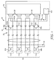
- Figure 1 is an electrical circuit diagram showing essential elements of a powered device 10 comprising a jack 20 according to the present invention, into which a plug 30 at the end of a data cable 40 is fully inserted.
- the cable 40 comprises eight signal wires 50 for transmitting electrical communication signals to and from the powered device 10. Out of these signal wires 50, a first signal wire 50a and a second signal wire 50b are used to also transmit electrical power from a direct current ("DC") power source 60 to the powered device 10.
- the power source 60 provides a DC voltage of 48 Volt and currents up to about 1 Ampere.
- the first signal wire 50a is electrically connected to the negative output of the power source 60
- the second signal wire 50b is electrically connected to the positive output of the power source 60.
- the power source 60 is located at the first end 70 of the cable 40 opposite to the second end 80 which connects to the powered device 10.
- the manner in which the power source is connected to the power-carrying signal wires 50a, 50b and the polarity is immaterial to the present invention. It is also immaterial which of the signal wires 50 are chosen to transmit power. In fact, power could be transmitted via a single signal wire 50 to the powered device 10, with the return path being formed by other elements outside the cable 40.
- the second end 80 of the cable 40 is provided with a plug 30, of which no mechanical elements are shown in Figure 1 .
- the plug 30 has eight plug signal contacts 90 for transmitting electrical communication signals, each is connected to one of the eight signal wires 50 of the cable 40.
- the jack 20 comprises eight jack signal contacts 100.
- each plug signal contact 90 is in electrical and mechanical contact with a corresponding jack signal contact 100, so that communication signals can be transmitted via the signal wires 50, the plug signal contacts 90 and the jack signal contacts 100.
- Figure 1 shows the plug 30 in the fully inserted position.
- Communication signals can be transmitted by the signal wires 50 forming four pairs 110 of signal wires 50 which carry an alternating voltage (“AC”) that codes the communication signals for each wire pair 110.
- AC alternating voltage
- Signals arriving at the jack signal contacts 100 are picked up by the powered device 10 using inductances 120.
- One inductance 110 picks up signals from one wire pair 110.
- These inductances 120 are arranged in the powered device 10, typically on a printed circuit board (“PCB”), which itself may be arranged in the jack 20 or remote from the jack 20.
- PCB printed circuit board
- the first signal wire 50a and the second signal wire 50b are electrically connected to respective first and second plug power contacts 90a, 90b.
- the plug power contacts 90a, 90b are plug signal contacts 90 that, in addition to transmitting communication signals, also can transmit electrical power.
- the first plug power contact 90a is in electrical contact with a first jack power contact 100a comprised in the jack 20
- the second plug power contact 90b is in electrical contact with a second jack power contact 1 OOb.
- the jack power contacts 100a, 100b are jack signal contacts 100 that, in addition to transmitting communication signals, also can transmit electrical power. Electrical power can thereby be transmitted into the jack 20.
- the powered device 20 requires power to operate, e.g. to process the communication signals received.
- the powered device 20 is not supplied with external power, other than through the signal wires 50a, 50b of the cable 40.
- the power consumption of the powered device 10 is represented by an electric load 130.
- a first electrical path 140a connects the first jack power contact 100a with the electric load 130, so that there is a galvanic connection between the negative output of the DC power source 60 and the electric load 130.
- a second electrical path 140b connects the second jack power contact 100b with the electric load 130, so that there is a galvanic connection between the positive output of the DC power source 60 and the electric load 130.
- the first electrical path 140a is part of the power path towards the load 130, with the second electrical path 140b forming part of the return path back to the source 60.
- the electric load 130 in the powered device 10 can thus be powered by the power source 60.
- the jack 20 comprises a switch 150 which connects two segments of the second electrical path 140b, when the switch 150 is closed, so that current can flow, via the second plug power contact 90b and the second jack power contact 100b and the second electrical path 140b, to the load 130 and, via the first electrical path 140a, the first jack power contact 100a and the first plug power contact 90a.
- the switch 150 When the switch 150 is open, no current can flow.
- the plug power contacts 90a, 90b are retracted from the corresponding jack power contacts 100a, 100b. If that happens while current is still allowed to flow through these power contacts, arc effects may occur which can deteriorate and eventually damage the power contacts both in the plug and in the jack.
- the switch 150 is used to interrupt the current over the power contacts before the plug power contacts 90a, 90b are retracted from the jack power contacts 100a, 100b. This is shown in more detail in the following Figures.
- FIG 2 is a sketched sectional view of a first communication connection jack 20 according to the invention, into which a plug 30 is fully inserted.
- the plug 30 is located at an end of a patch cable, and connected to a signal wire 50b of the cable.
- the jack 20 of Figure 2 comprises the corresponding elements of the electrical circuit shown in Figure 1 .
- the jack 20 comprises a cavity 160 for receiving the plug 30, and eight jack signal contacts 100, of which only one is visible in Figure 2 .
- the visible jack signal contact is the second jack power contact 100b.
- the visible jack signal contact is the second jack power contact 100b.
- the visible jack signal contact is the second jack power contact 100b.
- it is a resilient metal contact, supported mechanically on a printed circuit board (“PCB”) 170.
- Electronic circuitry on the PCB 170 e.g. inductances 120, picks up the communication signals transmitted via the second jack power contact 100b, and separates those signals form the power transmitted by the
- the plug signal contacts 90 make contact with the corresponding jack signal contacts 100, so that the signal contacts can transmit communication signals between the plug 30 and the jack 20, and so that those of the signal contacts 90, 100 that are operated as power contacts can transmit power from the plug 30 to the jack 20.
- the eight plug signal contacts 90 only one is visible in Figure 2 , namely the second plug power contact 90b.
- the plug 30 is fully inserted into the jack 20. In this position of the plug 30, all plug signal contacts 90 are in mechanical and electrical contact with the corresponding jack signal contacts 100, i.e.
- first and second plug power contacts 90a, 90b are in contact with the first and second jack signal contacts 100a, 100b.
- the fully-inserted position of the plug 30 in the jack 20 is mechanically defined by an abutment surface 230 of the jack 20, which provides an abutment for a corresponding surface on the plug 30 and limits further insertion in the insertion direction 190.
- the plug 30 is secured in the jack 20 by a securing element, which is a resilient latch 180.
- the securing element is comprised in the plug 30. It is contemplated, however, that a similar securing element may alternatively be comprised in the jack 20, or may be separate from both the jack 20 and the plug 30.
- the latch 180 comprises a latch nose 200 that engages behind a corresponding catch nose 210 in the jack 20, when the plug 30 is fully inserted into the jack 20. This engagement prevents retraction of the plug 30 from the jack 30 in a retraction direction, i.e. in a direction opposite to the insertion direction 190 and thus secures the plug 30 in the jack 20.
- Figure 2 shows the latch 180 in its engaged position, engaged with the jack 20.
- the latch 180 can be manually moved into a loose position. This movement is a movement of the latch 180 relative to the body 220 of the plug 30, and relative to the catch nose 210, in a direction orthogonal to the insertion direction 190, downward in Figure 2 .
- the loose position of the latch 180 is a position in which the latch 180 has been moved far enough out of the engaged position for the latch nose 200 to be disengaged from the catch nose 210 of the jack 20.
- the plug 30 can be retracted from the jack 20.
- the jack 20 also comprises a switch 150 and an actuator 240 for opening and closing the switch 150.
- the actuator 240 is in direct mechanical contact with the latch 180, actually a part of the outer surface of the actuator 240 is in mechanical contact with a part of the outer surface of the latch 180.
- the actuator 240 translates movement of the latch 180 into movement of the switch 150, so that, when the latch 180 is moved from the engaged position shown in Figure 2 into the loose position, the switch 150 is brought, via the actuator 240, from the closed state shown in Figure 2 into an open state, and such that, when the latch 180 moves by its resilience from the loose position into the engaged position, the switch 150 is brought, via the actuator 240, from the open state into the closed state.
- the latch 180 can only move or be moved into the engaged position when the plug 30 is fully inserted into the jack 20.
- the actuator 240 is constantly pushed towards the position of the latch 180 by a spring (not shown), so that when the latch 180 is pressed downward into its loose position, the actuator 240 follows the latch and thereby opens the switch 150, which in turn interrupts any current through the electrical path 140b.
- the switch 150 connects or disconnects two segments of the electrical path 140b between the second jack power contact 100b and an electric load 130. Electrical current can flow via this electrical path 140b from the positive output of the power source to the electric load 130.
- the return path for the current back to the power source is not shown in Figure 2 .
- This return path comprises a further electrical path 140a, the first jack power contact 100a and the first plug power contact 90, all of which are not shown in Figure 2 .
- the latch 180 Before the plug 30 can be retracted from the jack 20, the latch 180 must be disengaged from the jack 20 by moving it into the loose position. This movement of the latch 180 into the loose position opens the switch 150 and interrupts the current through the electrical path 140b. This results in the current being interrupted before the second plug power contact 90b is losing contact with the second jack power contact 100b, because this loss of contact only occurs when the plug 30 has been retracted from the jack 20 by a certain distance. The required distance is determined, inter alia, by the geometry and resilience of the second jack power contact 100b. Due to the fact that current through the power contacts 90b, 100b is shut off before the contacts are separated, no arc effects can occur between these contacts that might otherwise deteriorate the surfaces of these power contacts 90b, 100b.
- the jack 20 of Figure 2 may be used as part of a powered device 10, which also comprises the electric load 130, so that the powered device 10 is powered by the electrical power transmitted to the jack 20.
- FIG 3 in a sketched sectional view, shows the jack 20 and the plug 30 of Figure 2 with the latch 180 in the loose positon and the switch 150 in the open state.
- the actuator 240 has moved downward, following the movement of the latch 180.
- the switch 150 disconnects the two segments of the electrical path 140b and thereby switches off any current through the second plug power contact 90b and the second jack power contact 100b.
- the plug 30 is still fully inserted in the jack 20. With the latch 180 disengaged and in the loose position, the plug 30 can now be retracted from the jack 20.
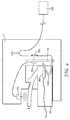
- FIG. 4 A second, different communication connection jack 21 is shown in Figure 4 , in a sketched sectional view similar to the view of Figures 2 and 3 . Certain elements are again drawn as symbols to enhance clarity of the Figure.
- the plug 30 is the same as the plug shown in Figures 2 and 3 .
- the jack 21 is similar to the first jack 20, except that it comprises a sensor 250 which senses the position of the latch 180 (engaged or loose).
- the sensor is an ultrasonic sensor, but other types of sensors can be used alternatively, e.g. inductive proximity sensors or optical sensors.
- the sensor 250 transmits its output signal to a control unit 260.
- the control unit 260 is arranged on the PCB 170, but generally the PCB 170 could be arranged in other places, inside the jack 21 or inside a powered device 10 in which the second jack 21 may be comprised.
- the control unit 260 actuates a switch 150 which connects or disconnects elements of an electrical path 140b between the second jack power contact 100b and the electric load 130, so that current can flow, via the electrical path 140b, to or from the electric load 130.
- the control unit 260 opens the switch 150 when it receives a signal from the sensor 250 that the latch 180 is going from the engaged position, shown in Figure 4 , into the loose position.
- the open switch 150 prevents current from flowing through the second plug power contact 90b, the second jack power contact 100b via the electrical path 140b to the electric load 130, or in the opposite direction. Hence the current is switched off before the plug 30 can be retracted from the second jack 21 and separation of the second plug power contact 90b from the second jack power contact 100b. When these contacts 90b, 100b eventually separate, no current flows and therefore no arc effects can occur between these contacts.
- control unit 260 closes the switch 150 when it receives a signal from the sensor 250 that the latch 180 is in the engaged position.
- This situation is shown in Figure 4 : The plug 30 is fully inserted into the jack 21, the latch 180 is in the engaged position, the sensor 250 senses the engaged position of the latch 180, sends a corresponding signal to the control unit 260, which closes the switch 150, so that current can flow from the second plug power contact 90b to the electric load 130.
- an element for securing the plug in the jack can be comprised in the jack.
- a third jack 22 according to the invention and a plug 31 are shown in a sketched sectional view.
- the jack 22 is connected to an end of a cable comprising a signal wire 50b, and it is fully inserted into the jack 22.
- the third jack 22 and the plug 31 are similar to the jacks and plugs shown before, except that the latch 181 for securing the plug 31 in the jack 22 is comprised in the jack 22.
- the latch 181 is resilient and can be bent upwards manually against an elastic force.
- the latch 181 has a latch nose 200, which can engage with a catch nose 210 on the plug 31.
- the plug 31 is shown fully inserted into the jack 22.
- the latch 181 is in its engaged position, so that the latch 181 is engaged with the plug 31. Specifically, it is engaged with the catch nose 210 of the plug 31.
- the latch 181 thereby secures the plug 31 in the jack 22, i.e. it prevents the plug 31 from being unintentionally retracted from the jack 22.
- the jack 22 comprises a switch 150 and a movable, rigid actuator 240 as described before.
- a lower surface of the actuator 240 is in mechanical contact with a surface portion of the latch 181.
- the actuator 240 operationally couples the switch 150 to the latch 181, so that, when the latch 181 is lifted and brought into the loose position, the switch 150 is brought from a closed state (shown in Figure 5 ) into an open state.
- a closed state shown in Figure 5
- the switch 150 In the closed state of the switch 150, it electrically connects two segments of the power path 140b between the second jack power contact 100b and the electric load 130, as described above for other jacks. In this closed state, power and current can flow through the second plug power contact 90b, the second jack power contact 100b, and the electrical path 140b to the electric load 130.
- the latch 181 can be brought into a loose position by moving an end portion 270 of the latch 181 away from the plug 31, i.e. by lifting it upwards in Figure 5 , whereby the latch nose 200 is disengaged from the catch 210.
- the plug 31 can be retracted from the jack 22.
- the switch 150 electrically disconnects two segments of the power path 140b between the second jack power contact 100b and the electric load 130. So by lifting the latch 181, the power patch 140b is interrupted, and any current through the second plug power contact 90b and the second jack power contact 100b is interrupted before these contacts separate, i.e. before the plug 31 can be retracted from the jack 22.
Landscapes
- Details Of Connecting Devices For Male And Female Coupling (AREA)
Abstract
Communication connection jack (20) for receiving a plug (30). The jack or the plug comprises a securing element (180) for securing the plug in the jack.
The jack comprises
a) a jack power contact (100b) for contacting a plug power contact, connectable to an electric load (130) for transmitting the power to the load; and
b) a switch (150) which can be brought into a closed state, in which it connects two segments of an electrical path (140b) between the jack power contact and the
electric load with each other, and into an open state in which it disconnects the two segments from each other.
a) a jack power contact (100b) for contacting a plug power contact, connectable to an electric load (130) for transmitting the power to the load; and
b) a switch (150) which can be brought into a closed state, in which it connects two segments of an electrical path (140b) between the jack power contact and the
electric load with each other, and into an open state in which it disconnects the two segments from each other.
When the plug is fully inserted into the jack, the switch is operationally coupled to the securing element such that, by bringing the securing element from the engaged position into the loose position, the switch is brought from the closed state into the open state.
Description
- The invention generally relates to jacks for receiving plugs for transmitting electrical signals in communication networks. Specifically, it relates to jacks that can receive plugs which transmit electrical signals and electrical power.
- Today there are many applications where the remote terminal equipment connected to a communication network is powered by a direct current ("DC" or "DC current"), which is fed through pairs of a balanced copper data cables. A common method is called Power-over-Ethernet ("PoE"). In such PoE-systems there are commonly up to four pairs of twisted wires, and the DC current is transmitted half on the first and half on the second wire of a twisted pair. One or two pairs bring the current to the remote equipment and the other pairs serve as electrical return path back to the power source, thereby closing the feeding circuit. Wires of such cables are connected to connectors (such as plugs, sockets, or jacks) at the end of the cables. Often, the wires and contacts of such connectors (plugs, sockets or jacks) are used for transmitting power, e.g. using currents of about one Ampere.
- An example of a data-transmitting system that also transmits power is shown in the U.S. patent application
US 2006/0046580 A1 , in which a system for locating corresponding ends of a patch cord comprises connectors having an integrated source of DC voltage which can be selectively placed across a pair of leads upon the activation of an integral switch within each said connector, and a lamp operatively attached across the corresponding pair which illuminates upon the activation of a momentary contact switch in each connector. - If a connector is disconnected without turning off the DC current before, e.g. a plug is retracted from a jack, sparks and electrical arcs can occur between power-transmitting contacts of the plug and the jack. If this is done frequently, these arcs degrade the surface of the connector contacts, thereby decreasing the lifetime of the connectors. It is therefore today recommended that, before separating the connectors, the user should shut down the power source first. Typically this is done by turning off the power supply unit, either remotely, e.g. using a network-management system, or locally, e.g. by manually interrupting an electrical connection to the power supply.
- A further U.S. patent application,
US 2005/0277320 A1 , presents a device having a manual interruption mechanism: The device comprises a movable part between a housing and an electronic board comprising conductive elements used to make the link between electrical contacts of a plug and electrical contacts of the electronic board. The user must bring the movable part into a position known as an insertion position or withdrawal position. As the plug is held by the movable part when it is inserted, it will not be possible to disconnect it unexpectedly. Arc effects therefore cannot take place since the position of insertion or disconnection alone is possible only when the passage of electrical energy does not occur. - In some scenarios, turning off or interrupting the power supply separately appears too difficult or too time consuming for the user, e.g. when charging batteries of laptop computers via the network connector using PoE. When the user of a laptop decides to leave, he will spontaneously retract the plug at the end of a network cable from the network cable jack on his computer. This can cause a spark, and the network cable jack of the laptop will be damaged. In consequence the laptop will sooner need repair.
- A laptop user can hardly be expected to separately turn off the current before disconnecting the network plug. More generally, it may be impractical to require a user to separately switch off or otherwise interrupt the power in a combined data/power transmitting network before disconnecting a network connector. It appears therefore desirable to provide systems that perform reliably over time, even if power is not separately switched off before disconnecting a network component. The present disclosure attempts to address this need.
- The present invention provides a communication connection jack for receiving a plug, the plug comprising
- i) a plug signal contact for transmitting electrical communication signals,
- ii) a plug power contact for transmitting power towards the jack, and
- iii) a securing element for securing the plug in the jack, wherein, when the plug is fully inserted into the jack, the securing element can be moved from an engaged position, in which the securing element is engaged with the jack and thereby secures the plug in the jack, into a loose position, in which the securing element is not engaged with the jack and the plug can be retracted from the jack; wherein the jack comprises
- a) a jack signal contact for contacting the plug signal contact when the plug is fully inserted into the jack and for transmitting electrical communication signals;
- b) a jack power contact for contacting the plug power contact when the plug is fully inserted into the jack, connectable to an electric load for transmitting the power to the load;
- c) a switch which can be brought into a closed state, in which the switch electrically connects two segments of an electrical path between the jack power contact and the electric load with each other, and into an open state in which the switch electrically disconnects the two segments from each other,
- The present invention also provides a communication connection jack for receiving a plug, the plug comprising
- i) a plug signal contact for transmitting electrical communication signals,
- ii) a plug power contact for transmitting power towards the jack;
- a) a jack signal contact for contacting the plug signal contact when the plug is fully inserted into the jack and for transmitting electrical communication signals;
- b) a jack power contact for contacting the plug power contact when the plug is fully inserted into the jack, connectable to an electric load for transmitting the power to the load;
- c) a switch which can be brought into a closed state, in which the switch electrically connects two segments of an electrical path between the jack power contact and the electric load with each other, and into an open state in which the switch electrically disconnects the two segments from each other,
- Independent from the securing element being comprised in the jack or in the plug, when the plug is fully inserted into the jack, the plug is secured in the jack by the securing element being in its engaged position. Before the plug can be retracted from its fully inserted position in the jack, i.e. before any plug power contact is separated from a corresponding jack power contact, the securing element must be brought into the loose position, in which it does not secure the plug in the jack any longer. By bringing the securing element into the loose position, the switch is brought into its open state, whereby the switch interrupts the current flowing through any plug power contact and the corresponding jack power contact, via the segments of the electrical path, to the electric load. With the current interrupted before a plug power contact and the corresponding jack power contact can be separated, electrical arcs cannot occur between these contacts, so that the risk of damage of the plug power contacts and of the jack power contacts is reduced.
- Plugs that can be received by a jack according to the present invention may be plugs for communication networks such as RJ45-type plugs, e.g. plugs according to the RJ45 standard as commonly used at the end of patch cords, that are adapted to transmit electrical power and communication signals parallel to each other. The plug may be a communication network plug. It may be a plug that is adapted for transmitting communication signals and electrical power in a "Power over Ethernet" connection according to the IEEE 802.3 standard including amendments IEEE 802.3af, IEEE 802.3at and IEEE 802.3bt.
- A plug which a jack according to the invention can receive, has a plug signal contact. It may have a plurality of plug signal contacts. The plug may comprise seven or eight plug signal contacts. The plug signal contact may be adapted for transmitting electrical communication signals. A plug signal contact may be resilient. It may comprise an elongate element of conductive metal through which communication signals are transmitted.
- A plug which a jack according to the invention can receive, has a plug power contact, e.g. a first plug power contact. Such a plug may comprise a second plug power contact. The plug power contact, or more generally any plug power contact, may have the same shape as a plug signal contact. All plug power contacts may have the same shape as a plug signal contact. The plug power contact may be adapted for transmitting power, e.g. by having a suitable cross sectional area or e.g. by comprising a specific surface layer, or e.g. by being made of a metal or alloy with higher conductivity. It may be adapted for transmitting power and electrical communication signals. Alternatively, the plug power contact may not be specifically adapted for transmitting power. For example, it may be identical in shape and properties to any plug signal contact.
- The plug power contact may be resilient. It may comprise an elongate element of conductive metal, through which power is transmitted.
- A plug that can be received in a jack according to the present disclosure may comprise a securing element for securing the plug in the jack, when the plug is fully inserted into the jack. The securing element may be a latch or comprise a latch. Alternative securing elements may comprise a clip, a lever, a push button, or a screw. Generally, a securing element may be resilient or elastic.
- Instead of the securing element being comprised in the plug, the securing element may be comprised in the jack. In this case, the plug may comprise a securement counterpart for engaging with a securing element of the jack for securing the plug in the jack, when the plug is fully inserted into the jack. The securement counterpart of the plug may be a catch for engaging with a securing element, e.g. a latch, of the jack for securing the plug in the jack, when the plug is fully inserted into the jack.
- The plug may have a plug body. In that case, a securing element of the plug may be attached to the plug body. Alternatively, the securing element may be integrally formed with the plug body. Also, a securement counterpart of the plug may be attached to the plug body or be integrally formed with the plug body.
- The term "jack" is used herein refers to sockets, e.g. connector sockets. A jack according to the present disclosure may be a jack for communication networks such as RJ45-type jacks, e.g. jacks as commonly used in electrical patch panels, that are adapted to transmit electrical power and communication signals parallel to each other. A jack according to the present disclosure may comprise a standard RJ45 jack. A jack according to the invention may be a communication network jack that is adapted to receive a standardized RJ45 plug. It may be a jack that is adapted for transmitting communication signals and electrical power in a "Power over Ethernet" connection according to the IEEE 802.3 standard.
- A jack according to the invention has a jack signal contact. It may have a plurality of jack signal contacts. The jack may comprise seven or eight jack signal contacts. A jack signal contact may be adapted for transmitting electrical communication signals. A jack signal contact may be suitably arranged and/or adapted for contacting a plug signal contact of a plug, when the plug is inserted, e.g. fully inserted, into the jack. A jack signal contact may be resilient. It may comprise an elongate element of conductive metal through which communication signals are transmitted.
- A jack according to the invention has a jack power contact, e.g. a first jack power contact. Such a jack may comprise a second jack power contact. The jack power contact, or more generally any jack power contact, may have the same shape as a jack signal contact. A jack power contact may be adapted for transmitting power, e.g. by having a suitable cross sectional area or e.g. by comprising a specific surface layer, or e.g. by being made of a metal or alloy with higher conductivity. The jack power contact may be suitably arranged and/or adapted for contacting a plug power contact of a plug, when the plug is inserted, e.g. fully inserted, into the jack. A jack power contact may be adapted for transmitting power and electrical communication signals, e.g. power and communication signals received via a plug power contact. Alternatively, the jack power contact may not be specifically adapted for transmitting power. For example, it may be identical in shape and properties to any jack signal contact.
- The jack power contact may be resilient. It may comprise an elongate element of conductive metal, through which power is transmitted.
- If the securing element is comprised in the plug, the jack may comprise a securement counterpart for engaging with the securing element of the plug for securing the plug in the jack, when the plug is fully inserted into the jack. The securement counterpart of the jack may be a catch for engaging with a securing element, e.g. a latch, of the plug for securing the plug in the jack, when the plug is fully inserted into the jack.
- Alternatively, the securing element may be comprised in the jack. Hence a jack according to the present disclosure may comprise a securing element for securing the plug in the jack, when the plug is fully inserted into the jack. The securing element may be a latch or comprise a latch. Alternative securing elements may comprise a clip, a lever, a push button, or a screw. Generally, a securing element may be resilient or elastic. A jack according to the present invention may only comprise a single securing element, i.e. it may be free of any further securing element. A jack according to the present invention may be adapted to receive a plug comprising no securing element, i.e. a plug being free of any securing element.
- Generally, the jack may have a jack body. In that case, a securing element of the jack may be attached to the jack body. Alternatively, the securing element may be integrally formed with the jack body. Also, a securement counterpart of the jack may be attached to the jack body or be integrally formed with the jack body.
- The switch may be an electro-mechanical switch or an electronic switch. The switch may comprise metallic contacts or a semiconducting element, e.g. a transistor, for connecting or disconnecting segments of the electrical path. The switch may be adapted to connect and disconnect segments of two, three, four or more electrical paths.
- When the plug is fully inserted into the jack, electrical power is supposed to be provided to an electric load, via the plug power contact, the corresponding jack power contact and an electrical path between the jack power contact and the electric load. The electric load may be, for example, an LED on the jack, a surveillance camera, a remote-controlled lighting device, or a rechargeable battery of a laptop computer, which is connected to a communication network via the jack and the plug. The power fed to the plug power contact is transmitted to the jack power contact, by virtue of the plug power contact contacting the jack power contact. The electrical path transmits, or is adapted to transmit, the power from the jack power contact to the electric load.
- The electrical path may comprise one or two or more segments. A segment may comprise a conductive trace on a circuit board or a conductive wire or a conductor element. If all segments of the electrical path are connected with each other, current can flow from the jack power contact to the electric load. The switch, when in its closed state, connects two segments of the electrical path, and when in its open state, the switch disconnects the two segments from each other. In its open state, the switch inhibits the electrical current through the electrical path. If all other segments are electrically connected with each other, the state of the switch determines if power can be transmitted to the electric load or not.
- Transmission of electrical power requires a circuit having a power path, i.e. a forward path, and a return path, often referred to as plus and minus. The electrical path from the jack power contact to the electric load may form the power path or the return path of a power-transmitting circuit. If the electrical path via the jack power contact is the power path, the return path may be formed by elements on electrical ground. Alternatively, the jack may comprise a second jack power contact, for contacting a second plug power contact on the plug, both power contacts being comprised in an electrical return path from the electric load to the power source.
- In the context of the present disclosure, a plug is fully inserted into the jack when the plug is in a position which is achieved by inserting the plug into the jack in a insertion direction, defined by the jack, far enough for hitting a stopper in the jack that defines the fully inserted position of the plug in the jack. The fully inserted position is the position of deepest insertion, in the insertion direction, of the plug into the jack. A jack may thus comprise a stopper which defines a fully inserted position of the plug in the jack. Most jacks are designed such that, when gradually inserting a plug into the jack up to the fully inserted position, the plug signal contacts and the jack signal contacts are in contact well before the plug is fully inserted. A jack according to the invention may be adapted such that the jack power contact contacts the plug power contact in the fully inserted position, and such that the plug power contact loses contact with the jack power contact when the plug has been gradually retracted from the fully inserted position by a certain distance, e.g. retracted by 1mm.
- Independent of the securing element being comprised in the plug or in the jack, the switch of a jack according to the present disclosure is arranged and adapted such that, when the plug is fully inserted into the jack, the switch is operationally coupled to the securing element such that, by bringing the securing element from the engaged position into the loose position, the switch is brought from the closed state into the open state.
- The term "operationally coupled" as used herein refers to two elements being linked such that an action or change on one element causes an action or change on the other element. Specifically, when the position of the securing element is changed, the state of the switch is changed, too.
- Such an operational coupling can be achieved in various ways. The operational coupling may be, for example, a mechanical coupling, where a movement of the securing element is converted by mechanical means, e.g. such as levers or bars or strings, into a movement of an element of the switch, so that the switch changes its state and thereby connects or disconnects two segments of the electrical path.
- An alternative operational coupling may be based on a sensor which senses the position ("engaged" or "loose") of the securing element, and which generates an electrical or optical signal, which in turn causes another element, e.g. an electric motor or an electric circuit, to bring the switch from one state into the other state ("closed" or "open") corresponding to the position of the securing element, when the position of the securing element changes. The sensor and the switch may be arranged in different locations remote from each other, or alternatively they may be arranged close or even adjacent to each other. The sensor may be comprised in the switch or in the jack.
- Operational coupling may be electric or electronic coupling, e.g. coupling via electrical signals. Operational coupling may be optical coupling, e.g. via optical signals. Alternatively, operational coupling may be mechanical coupling.
- The switch may, for example, be mechanically coupled directly to the securing element. For example, a surface of the switch may be in mechanical contact with a surface of the securing element in the open or in the closed state of the switch, when the plug is fully inserted into the jack.
- Alternatively, the switch may be mechanically coupled indirectly to the securing element. In such jacks, the switch may be in mechanical contact with an intermediate component or a plurality of intermediate components, which in turn is/are in mechanical contact with the securing element in the open or in the closed state of the switch, when the plug is fully inserted into the jack.
- Where the securing element is comprised in the plug, the jack may provide a recess for receiving a portion of the securing element, when the plug is fully inserted into the jack. In such jacks, the switch may be arranged in the vicinity of the recess. Where the jack comprises a securement counterpart, the switch may be arranged in the vicinity of the securement counterpart. Alternatively, where the securement element is comprised in the jack, the switch may be arranged in the vicinity of the securement element. Such arrangements may render the mechanical contact between securing element and switch simpler und thus more cost-effective to manufacture and more reliable in use.
- Where the securing element is a latch comprised in the plug, a jack according to the invention may further comprise a catch portion, adapted to engage with the securing element for securing the plug in the jack. Where the securing element is a latch comprised in the jack, a plug that can be received by a jack according to the invention may further comprise a catch portion, adapted to engage with the securing element for securing the plug in the jack. In both cases, a dedicated catch portion may make the engagement between plug and jack more reliable.
- The securing element may be resilient. It may comprise a resilient portion. A resilient securing element which is partially or completely resilient may facilitate a particularly quick engagement between the securing element and the jack or the plug, as the case may be.
- The jack power contact may be adapted for also transmitting communication signals. The jack power contact may have a shape that is identical to a shape of a jack signal contact. A jack power contact that can also transmit communication signals may increase the data transmission rate which the jack can handle. The jack power contact may thus perform two functions simultaneously, namely transmission of power and of data. The power and the data can be easily separated by suitable, known electronic circuitry. Thereby, such a jack may make a separate further jack signal contact obsolete.
- The electric load may be arranged in or on the jack. The electric load may be, for example, a light-emitting diode, mounted in the jack such as to be visible to an operator, which provides a visual indication to the operator.
- Alternatively, the electric load may be arranged remote from the jack. In that case, it may be connected to the jack via a wire or cable.
- The switch may comprise a movable or pivotable actuator. When the plug is fully inserted into the jack and the securing element is in the engaged position, the switch may be operationally coupled to the securing element by an actuator. The actuator may be comprised in the jack. Alternatively the actuator may be comprised in the plug or it may be arranged outside the jack and outside the plug.
- When the plug is fully inserted into the jack and the securing element is in the engaged position, the switch may be operationally coupled to the securing element by a surface of the actuator being in mechanical contact with a surface of the securing element. Alternatively, or in addition, when the plug is fully inserted into the jack and the securing element is in the loose position, the switch may be operationally coupled to the securing element by a surface of the actuator being in mechanical contact with a surface of the securing element.
- More generally, the switch may be comprised in a switching portion of the jack, which switching portion may further comprise an actuator for bringing the switch into an open or a closed state. When the plug is fully inserted into the jack and the securing element is in the engaged position, the switch may be operationally coupled to the securing element by a portion of the actuator being in mechanical contact with a surface of the securing element. Alternatively, or in addition, when the plug is fully inserted into the jack and the securing element is in the loose position, the switch may be operationally coupled to the securing element by a portion of the switch being in mechanical contact with a surface of the securing element.
- Such arrangements may provide for a particularly direct and therefore particularly reliable coupling between the securing element and the switch. Via the actuator, or via the contacting surfaces of the actuator, a movement of a portion of the securing element may be translated directly into a movement of a portion of the switch, whereby the switch is brought from the closed state into the open state or vice versa.
- The jack may be adapted such that the plug signal contact and the jack signal contact are electrically connected with each other when the plug is fully inserted into the jack. In addition, the jack may also be adapted such that the plug signal contact and the jack signal contact are not electrically connected with each other when the plug is not fully inserted, or partially inserted, into the jack. By such an adaptation the insertion position at which the signal contacts make contact with each other may be better defined. This in turn may result in a smaller dimension of the jack and a more reliable electrical connection between the plug signal contact and the jack signal contact.
- The jack may be adapted for receiving a standard RJ45 plug. The jack may comprise a jack receptacle, adapted for receiving a standard RJ45 plug. The jack may comprise a jack receptacle, shaped for receiving a standard RJ45 plug. The jack receptacle may be shaped such as a receptacle of a standard RJ45 jack. The jack may comprise a receptacle of a standard RJ45 jack for receiving a standard RJ45 plug. Such arrangements may allow the jack to cooperate with standard RJ45 plugs, which makes the jack according to the invention more versatile and may reduce its manufacturing cost. Using a standard RJ45 jack receptacle in a jack according to the invention may also reduce manufacturing cost of jacks according to the invention. Standard RJ45 jacks are jacks according to any version or addition of any RJ45 industry standard.
- The switch may be adapted to connect and disconnect segments of an electrical path transmitting a power of at least 10 Watt, a power of at least 20 Watt, 50 Watt, or at least 80 Watt. It may be adapted to connect and disconnect segments of an electrical path transmitting a current of at least 0.2 Ampere, a current of at least 0.5 Ampere, at least 1.0 Ampere or at least 2.0 Ampere. Such switches can be reliably operated many times with little risk of failure. Thereby they can make a jack according to the invention more reliable.
- The jack may comprise a sensor for sensing the engaged position and/or the loose position of the securing element. The sensor may generate an electrical or an optical or a radio signal for transmission to the switch. The sensor may, for example, be a mechanical sensor, a proximity sensor, a magnetic sensor, or an optical sensor. Detection of the position of the securing element by a sensor may allow to change the state of the switch in non-mechanical ways, e.g. electrically. If the sensor senses that the securing element has been brought from the engaged position into the loose position, it may generate a signal that can be transmitted to the switch and which causes the switch to change its state from the closed state to the open state. In the open state, the transmission of power and of current from the jack power contact to the electrical load is interrupted, so that no arc effects can occur when the plug power contact is separated from the jack power contact shortly afterwards.
- The jack may comprise a circuit board, on which the switch is arranged. Arrangement on a circuit board allows the switch to be securely mounted and reliably connected electrically. Conductive traces on a circuit board are often considered more reliable than individual wires, hence the connection of the switch may be more reliable. A circuit board may facilitate the electrical connection of wires to the switch and/or to the electric load.
- The invention provides, in one aspect, a jack module or a patch panel, comprising a connection jack as described in this disclosure. A jack module may be an element comprising a plurality of jacks. A jack module or a patch panel are elements that may provide for cost-effective mounting of a plurality of jacks and facilitate connection of a larger number of plugs to a plurality of jacks.
- The invention also provides a powered device in a "Power over Ethernet" communication connection, comprising a communication connection jack as described in this disclosure. Such a device may be more reliable than devices using other jacks. The presence of a jack according to the present disclosure may bring some advantages described herein for the jack. In particular, the degradation of contacts due to electrical arc effects may be reduced.
- An existing jack having a jack signal contact and a jack power contact may be upgraded to a jack according to the invention. This may be done by adding an electrical path from the jack power contact towards an electric load, and a switch, which is operable to connect and disconnect two segments of the electrical path. Therefore, the invention also provides a method of converting an RJ45 into a jack according to the invention, as described in this disclosure, the method comprising the steps of
- a) providing an RJ45 jack for receiving an RJ45 plug, the jack comprising a jack power contact for receiving electrical power from a corresponding plug power contact, and for transmitting the power to an electric load;
- b) providing a switch which can be brought into a closed state, in which the switch electrically connects two segments of an electrical path with each other, and into an open state in which the switch electrically disconnects the two segments from each other; and
- c) electrically connecting the switch to the jack power contact, and arranging the switch such that, when the plug is fully inserted into the jack, the switch is operationally coupled to a securing element for securing the plug in the jack, such that, by bringing the securing element from an engaged position, in which the securing element secures the plug in the jack, into a loose position, in which the securing element is not engaged with the jack and the plug can be retracted from the jack, the switch is brought from the closed state into the open state, whereby the switch disconnects two segments of an electrical path between the jack power contact and the electric load.
- Such a method may allow to upgrade a regular jack, available readily and at comparatively low cost, to a jack according to the invention easily and at particularly low cost, thereby increasing the likelihood of reducing contact erosion and obtaining longer lifetime.
- The invention will now be described in more detail with reference to the following Figures exemplifying particular embodiments of the invention:
- Fig. 1
- Electrical circuit diagram of a cable and a jack according to the invention;
- Fig. 2
- Sketched sectional view of a first jack according to the invention and a plug, with the securing element in its engaged position;
- Fig. 3
- Sketched sectional view of the first jack and the plug of
Fig. 2 , with the securing element in its loose position; - Fig. 4
- Sketched sectional view of a second jack according to the invention and a plug, where the jack comprises a sensor; and
- Fig. 5
- Sketched sectional view of a third jack according to the invention and a plug, where the securing element is comprised in the jack.
-
Figure 1 is an electrical circuit diagram showing essential elements of apowered device 10 comprising ajack 20 according to the present invention, into which aplug 30 at the end of adata cable 40 is fully inserted. - The
cable 40 comprises eightsignal wires 50 for transmitting electrical communication signals to and from thepowered device 10. Out of thesesignal wires 50, afirst signal wire 50a and asecond signal wire 50b are used to also transmit electrical power from a direct current ("DC")power source 60 to thepowered device 10. Thepower source 60 provides a DC voltage of 48 Volt and currents up to about 1 Ampere. Thefirst signal wire 50a is electrically connected to the negative output of thepower source 60, thesecond signal wire 50b is electrically connected to the positive output of thepower source 60. Thepower source 60 is located at the first end 70 of thecable 40 opposite to thesecond end 80 which connects to thepowered device 10. The manner in which the power source is connected to the power-carryingsignal wires signal wires 50 are chosen to transmit power. In fact, power could be transmitted via asingle signal wire 50 to thepowered device 10, with the return path being formed by other elements outside thecable 40. - The
second end 80 of thecable 40 is provided with aplug 30, of which no mechanical elements are shown inFigure 1 . Theplug 30 has eightplug signal contacts 90 for transmitting electrical communication signals, each is connected to one of the eightsignal wires 50 of thecable 40. - The
jack 20 comprises eightjack signal contacts 100. When theplug 30 is fully inserted into thejack 20, eachplug signal contact 90 is in electrical and mechanical contact with a correspondingjack signal contact 100, so that communication signals can be transmitted via thesignal wires 50, theplug signal contacts 90 and thejack signal contacts 100.Figure 1 shows theplug 30 in the fully inserted position. - Communication signals can be transmitted by the
signal wires 50 forming fourpairs 110 ofsignal wires 50 which carry an alternating voltage ("AC") that codes the communication signals for eachwire pair 110. Signals arriving at thejack signal contacts 100 are picked up by thepowered device 10 usinginductances 120. Oneinductance 110 picks up signals from onewire pair 110. Theseinductances 120 are arranged in thepowered device 10, typically on a printed circuit board ("PCB"), which itself may be arranged in thejack 20 or remote from thejack 20. Thepowered device 10 can then receive the communication signals and process them. - The
first signal wire 50a and thesecond signal wire 50b, i.e. thesignal wires 50 transmitting electrical power, are electrically connected to respective first and secondplug power contacts plug power contacts plug signal contacts 90 that, in addition to transmitting communication signals, also can transmit electrical power. When theplug 30 is fully inserted into thejack 20, the firstplug power contact 90a is in electrical contact with a firstjack power contact 100a comprised in thejack 20, and the secondplug power contact 90b is in electrical contact with a second jack power contact 1 OOb. Thejack power contacts jack signal contacts 100 that, in addition to transmitting communication signals, also can transmit electrical power. Electrical power can thereby be transmitted into thejack 20. - The
powered device 20 requires power to operate, e.g. to process the communication signals received. Thepowered device 20 is not supplied with external power, other than through thesignal wires cable 40. In the diagram ofFigure 1 , the power consumption of thepowered device 10 is represented by anelectric load 130. - A first
electrical path 140a connects the firstjack power contact 100a with theelectric load 130, so that there is a galvanic connection between the negative output of theDC power source 60 and theelectric load 130. Similarly, a secondelectrical path 140b connects the secondjack power contact 100b with theelectric load 130, so that there is a galvanic connection between the positive output of theDC power source 60 and theelectric load 130. The firstelectrical path 140a is part of the power path towards theload 130, with the secondelectrical path 140b forming part of the return path back to thesource 60. Theelectric load 130 in thepowered device 10 can thus be powered by thepower source 60. - The
jack 20 comprises aswitch 150 which connects two segments of the secondelectrical path 140b, when theswitch 150 is closed, so that current can flow, via the secondplug power contact 90b and the secondjack power contact 100b and the secondelectrical path 140b, to theload 130 and, via the firstelectrical path 140a, the firstjack power contact 100a and the firstplug power contact 90a. When theswitch 150 is open, no current can flow. - When the
plug 30 is retracted form thejack 20, theplug power contacts jack power contacts jack 20 according to the invention, theswitch 150 is used to interrupt the current over the power contacts before theplug power contacts jack power contacts -
Figure 2 is a sketched sectional view of a firstcommunication connection jack 20 according to the invention, into which aplug 30 is fully inserted. Theplug 30 is located at an end of a patch cable, and connected to asignal wire 50b of the cable. Thejack 20 ofFigure 2 comprises the corresponding elements of the electrical circuit shown inFigure 1 . Thejack 20 comprises acavity 160 for receiving theplug 30, and eightjack signal contacts 100, of which only one is visible inFigure 2 . The visible jack signal contact is the secondjack power contact 100b. Like alljack signal contacts 100, it is a resilient metal contact, supported mechanically on a printed circuit board ("PCB") 170. Electronic circuitry on thePCB 170,e.g. inductances 120, picks up the communication signals transmitted via the secondjack power contact 100b, and separates those signals form the power transmitted by the same secondjack power contact 100b. - When the
plug 30 is inserted into thejack cavity 160 in aninsertion direction 190 defined by the geometry of thejack cavity 160, theplug signal contacts 90 make contact with the correspondingjack signal contacts 100, so that the signal contacts can transmit communication signals between theplug 30 and thejack 20, and so that those of thesignal contacts plug 30 to thejack 20. Of the eightplug signal contacts 90, only one is visible inFigure 2 , namely the secondplug power contact 90b. Theplug 30 is fully inserted into thejack 20. In this position of theplug 30, all plugsignal contacts 90 are in mechanical and electrical contact with the correspondingjack signal contacts 100, i.e. also the first and secondplug power contacts jack signal contacts plug 30 in thejack 20 is mechanically defined by anabutment surface 230 of thejack 20, which provides an abutment for a corresponding surface on theplug 30 and limits further insertion in theinsertion direction 190. - The
plug 30 is secured in thejack 20 by a securing element, which is aresilient latch 180. In the embodiment shown inFigure 2 , the securing element is comprised in theplug 30. It is contemplated, however, that a similar securing element may alternatively be comprised in thejack 20, or may be separate from both thejack 20 and theplug 30. Thelatch 180 comprises alatch nose 200 that engages behind acorresponding catch nose 210 in thejack 20, when theplug 30 is fully inserted into thejack 20. This engagement prevents retraction of theplug 30 from thejack 30 in a retraction direction, i.e. in a direction opposite to theinsertion direction 190 and thus secures theplug 30 in thejack 20. -
Figure 2 shows thelatch 180 in its engaged position, engaged with thejack 20. In order to allow retraction of theplug 30 from thejack 20, thelatch 180 can be manually moved into a loose position. This movement is a movement of thelatch 180 relative to thebody 220 of theplug 30, and relative to thecatch nose 210, in a direction orthogonal to theinsertion direction 190, downward inFigure 2 . The loose position of thelatch 180 is a position in which thelatch 180 has been moved far enough out of the engaged position for thelatch nose 200 to be disengaged from thecatch nose 210 of thejack 20. When thelatch 180 is in the loose position, theplug 30 can be retracted from thejack 20. - The
jack 20 also comprises aswitch 150 and anactuator 240 for opening and closing theswitch 150. Theactuator 240 is in direct mechanical contact with thelatch 180, actually a part of the outer surface of theactuator 240 is in mechanical contact with a part of the outer surface of thelatch 180. Theactuator 240 translates movement of thelatch 180 into movement of theswitch 150, so that, when thelatch 180 is moved from the engaged position shown inFigure 2 into the loose position, theswitch 150 is brought, via theactuator 240, from the closed state shown inFigure 2 into an open state, and such that, when thelatch 180 moves by its resilience from the loose position into the engaged position, theswitch 150 is brought, via theactuator 240, from the open state into the closed state. Thelatch 180 can only move or be moved into the engaged position when theplug 30 is fully inserted into thejack 20. - The
actuator 240 is constantly pushed towards the position of thelatch 180 by a spring (not shown), so that when thelatch 180 is pressed downward into its loose position, theactuator 240 follows the latch and thereby opens theswitch 150, which in turn interrupts any current through theelectrical path 140b. - The
switch 150 connects or disconnects two segments of theelectrical path 140b between the secondjack power contact 100b and anelectric load 130. Electrical current can flow via thiselectrical path 140b from the positive output of the power source to theelectric load 130. The return path for the current back to the power source is not shown inFigure 2 . This return path comprises a furtherelectrical path 140a, the firstjack power contact 100a and the firstplug power contact 90, all of which are not shown inFigure 2 . - Before the
plug 30 can be retracted from thejack 20, thelatch 180 must be disengaged from thejack 20 by moving it into the loose position. This movement of thelatch 180 into the loose position opens theswitch 150 and interrupts the current through theelectrical path 140b. This results in the current being interrupted before the secondplug power contact 90b is losing contact with the secondjack power contact 100b, because this loss of contact only occurs when theplug 30 has been retracted from thejack 20 by a certain distance. The required distance is determined, inter alia, by the geometry and resilience of the secondjack power contact 100b. Due to the fact that current through thepower contacts power contacts - The
jack 20 ofFigure 2 may be used as part of apowered device 10, which also comprises theelectric load 130, so that thepowered device 10 is powered by the electrical power transmitted to thejack 20. -
Figure 3 , in a sketched sectional view, shows thejack 20 and theplug 30 ofFigure 2 with thelatch 180 in the loose positon and theswitch 150 in the open state. Theactuator 240 has moved downward, following the movement of thelatch 180. In the open state, theswitch 150 disconnects the two segments of theelectrical path 140b and thereby switches off any current through the secondplug power contact 90b and the secondjack power contact 100b. Theplug 30 is still fully inserted in thejack 20. With thelatch 180 disengaged and in the loose position, theplug 30 can now be retracted from thejack 20. - A second, different
communication connection jack 21 is shown inFigure 4 , in a sketched sectional view similar to the view ofFigures 2 and3 . Certain elements are again drawn as symbols to enhance clarity of the Figure. - The
plug 30 is the same as the plug shown inFigures 2 and3 . Thejack 21 is similar to thefirst jack 20, except that it comprises asensor 250 which senses the position of the latch 180 (engaged or loose). In the embodiment shown, the sensor is an ultrasonic sensor, but other types of sensors can be used alternatively, e.g. inductive proximity sensors or optical sensors. - The
sensor 250 transmits its output signal to acontrol unit 260. In the present embodiment, thecontrol unit 260 is arranged on thePCB 170, but generally thePCB 170 could be arranged in other places, inside thejack 21 or inside apowered device 10 in which thesecond jack 21 may be comprised. Thecontrol unit 260 actuates aswitch 150 which connects or disconnects elements of anelectrical path 140b between the secondjack power contact 100b and theelectric load 130, so that current can flow, via theelectrical path 140b, to or from theelectric load 130. - Similar to the setup of the
first jack 20, thecontrol unit 260 opens theswitch 150 when it receives a signal from thesensor 250 that thelatch 180 is going from the engaged position, shown inFigure 4 , into the loose position. Theopen switch 150 prevents current from flowing through the secondplug power contact 90b, the secondjack power contact 100b via theelectrical path 140b to theelectric load 130, or in the opposite direction. Hence the current is switched off before theplug 30 can be retracted from thesecond jack 21 and separation of the secondplug power contact 90b from the secondjack power contact 100b. When thesecontacts - Also, the
control unit 260 closes theswitch 150 when it receives a signal from thesensor 250 that thelatch 180 is in the engaged position. This situation is shown inFigure 4 : Theplug 30 is fully inserted into thejack 21, thelatch 180 is in the engaged position, thesensor 250 senses the engaged position of thelatch 180, sends a corresponding signal to thecontrol unit 260, which closes theswitch 150, so that current can flow from the secondplug power contact 90b to theelectric load 130. - Alternatively, an element for securing the plug in the jack, like for example the latch, can be comprised in the jack. In
Figure 5 , athird jack 22 according to the invention and aplug 31 are shown in a sketched sectional view. Thejack 22 is connected to an end of a cable comprising asignal wire 50b, and it is fully inserted into thejack 22. Thethird jack 22 and theplug 31 are similar to the jacks and plugs shown before, except that thelatch 181 for securing theplug 31 in thejack 22 is comprised in thejack 22. Thelatch 181 is resilient and can be bent upwards manually against an elastic force. Thelatch 181 has alatch nose 200, which can engage with acatch nose 210 on theplug 31. Theplug 31 is shown fully inserted into thejack 22. In this position of theplug 31, thelatch 181 is in its engaged position, so that thelatch 181 is engaged with theplug 31. Specifically, it is engaged with thecatch nose 210 of theplug 31. Thelatch 181 thereby secures theplug 31 in thejack 22, i.e. it prevents theplug 31 from being unintentionally retracted from thejack 22. - The
jack 22 comprises aswitch 150 and a movable,rigid actuator 240 as described before. A lower surface of theactuator 240 is in mechanical contact with a surface portion of thelatch 181. Theactuator 240 operationally couples theswitch 150 to thelatch 181, so that, when thelatch 181 is lifted and brought into the loose position, theswitch 150 is brought from a closed state (shown inFigure 5 ) into an open state. In the closed state of theswitch 150, it electrically connects two segments of thepower path 140b between the secondjack power contact 100b and theelectric load 130, as described above for other jacks. In this closed state, power and current can flow through the secondplug power contact 90b, the secondjack power contact 100b, and theelectrical path 140b to theelectric load 130. - For retracting the
plug 31 from thejack 22, thelatch 181 can be brought into a loose position by moving anend portion 270 of thelatch 181 away from theplug 31, i.e. by lifting it upwards inFigure 5 , whereby thelatch nose 200 is disengaged from thecatch 210. When thelatch 181 is in its loose position, theplug 31 can be retracted from thejack 22. - In the open state, the
switch 150 electrically disconnects two segments of thepower path 140b between the secondjack power contact 100b and theelectric load 130. So by lifting thelatch 181, thepower patch 140b is interrupted, and any current through the secondplug power contact 90b and the secondjack power contact 100b is interrupted before these contacts separate, i.e. before theplug 31 can be retracted from thejack 22.
a securing element for securing the plug in the jack, wherein, when the plug is fully inserted into the jack, the securing element can be moved from an engaged position, in which the securing element is engaged with the plug and thereby secures the plug in the jack, into a loose position, in which the securing element is not engaged with the plug and the plug can be retracted from the jack; wherein the jack further comprises
Claims (14)
- Communication connection jack (20, 21) for receiving a plug (30),
the plug comprisingi) a plug signal contact (90) for transmitting electrical communication signals,ii) a plug power contact (90a, 90b) for transmitting power towards the jack, andiii) a securing element (180) for securing the plug in the jack, wherein, when the plug is fully inserted into the jack, the securing element can be moved from an engaged position, in which the securing element is engaged with the jack and thereby secures the plug in the jack, into a loose position, in which the securing element is not engaged with the jack and the plug can be retracted from the jack;wherein the jack comprisesa) a jack signal contact (100) for contacting the plug signal contact when the plug is fully inserted into the jack and for transmitting electrical communication signals;b) a jack power contact (100a, 100b) for contacting the plug power contact when the plug is fully inserted into the jack, connectable to an electric load (130) for transmitting the power to the load;c) a switch (150) which can be brought into a closed state, in which the switch electrically connects two segments of an electrical path (140a, 140b) between the jack power contact and the electric load with each other, and into an open state in which the switch electrically disconnects the two segments from each other,characterized in that the switch is arranged and adapted such that, when the plug is fully inserted into the jack, the switch is operationally coupled to the securing element such that, by bringing the securing element from the engaged position into the loose position, the switch is brought from the closed state into the open state. - Communication connection jack (22) for receiving a plug (30, 31),
the plug comprisingi) a plug signal contact (90) for transmitting electrical communication signals,ii) a plug power contact (90a, 90b) for transmitting power towards the jack;wherein the jack comprises
a securing element (181) for securing the plug in the jack, wherein, when the plug is fully inserted into the jack, the securing element can be moved from an engaged position, in which the securing element is engaged with the plug and thereby secures the plug in the jack, into a loose position, in which the securing element is not engaged with the plug and the plug can be retracted from the jack; wherein the jack further comprisesa) a jack signal contact (100) for contacting the plug signal contact when the plug is fully inserted into the jack and for transmitting electrical communication signals;b) a jack power contact (100a, 100b) for contacting the plug power contact when the plug is fully inserted into the jack, connectable to an electric load (130) for transmitting the power to the load;c) a switch (150) which can be brought into a closed state, in which the switch electrically connects two segments of an electrical path (140a, 140b) between the jack power contact and the electric load with each other, and into an open state in which the switch electrically disconnects the two segments from each other,characterized in that the switch is arranged and adapted such that, when the plug is fully inserted into the jack, the switch is operationally coupled to the securing element such that, by bringing the securing element from the engaged position into the loose position, the switch is brought from the closed state into the open state. - Communication connection jack according to any one of the preceding claims, further comprising a catch portion (210), adapted to engage with the securing element (180) for securing the plug in the jack.
- Communication connection jack according to any one of the preceding claims, wherein the securing element is resilient or comprises a resilient portion.
- Communication connection jack according to any one of the preceding claims, wherein the jack power contact (100a, 100b) is adapted for also transmitting communication signals.
- Communication connection jack according to any one of the preceding claims, wherein the switch (150) comprises a movable or pivotable actuator (240), wherein, when the plug is fully inserted into the jack and the securing element is in the engaged position, a surface of the actuator is in mechanical contact with a surface of the securing element.
- Communication connection jack according to any one of the preceding claims, wherein the jack is adapted such that the plug power contact and the jack power contact are electrically connected with each other when the plug is fully inserted into the jack, and such that the plug power contact and the jack power contact are not electrically connected with each other when the plug is not fully inserted, or is only partially inserted, into the jack.
- Communication connection jack according to any one of the preceding claims, wherein the jack comprises a standard RJ45 jack, or wherein the jack is adapted for receiving a standard RJ45 plug.
- Communication connection jack according to any one of the preceding claims, wherein the switch (150) is adapted to connect and disconnect segments of an electrical path (140a, 140b) transmitting a power of at least 10 Watt, and/or transmitting currents of at least 0.5 Ampere.
- Communication connection jack according to any one of the preceding claims, wherein the jack comprises a sensor (250) for sensing the engaged position and/or the loose position of the securing element (181).
- Communication connection jack according to any one of the preceding claims, wherein the jack comprises a circuit board (170), on which the switch (150) is arranged.
- Jack module or patch panel, comprising a connection jack (20, 21, 22) according to any one of the preceding claims.
- Powered device (10) for a "Power over Ethernet" communication connection, comprising a communication connection jack (20, 21, 22) according to any one of the preceding claims.
- Method of converting an RJ45 jack into a communication connection jack (20, 21, 22) according to any one of claims 1 to 11, comprising the steps ofa) providing an RJ45 jack for receiving an RJ45 plug, the jack comprising a jack power contact (100a, 100b) for receiving electrical power from a corresponding plug power contact (90a, 90b), and for transmitting the power to an electric load (130);b) providing a switch (150) which can be brought into a closed state, in which the switch electrically connects two segments of an electrical path (140a, 140b) with each other, and into an open state in which the switch electrically disconnects the two segments from each other; andc) electrically connecting the switch to the jack power contact, and arranging the switch such that, when the plug is fully inserted into the jack, the switch is operationally coupled to a securing element (180, 181) for securing the plug in the jack, such that, by bringing the securing element from an engaged position, in which the securing element secures the plug in the jack, into a loose position, in which the securing element is not engaged with the jack and the plug can be retracted from the jack, the switch is brought from the closed state into the open state, whereby the switch disconnects two segments of the electrical path between the jack power contact and the electric load.
Priority Applications (1)
| Application Number | Priority Date | Filing Date | Title |
|---|---|---|---|
| EP16170314.5A EP3247004A1 (en) | 2016-05-19 | 2016-05-19 | Jack for transmitting signal and power |
Applications Claiming Priority (1)
| Application Number | Priority Date | Filing Date | Title |
|---|---|---|---|
| EP16170314.5A EP3247004A1 (en) | 2016-05-19 | 2016-05-19 | Jack for transmitting signal and power |
Publications (1)
| Publication Number | Publication Date |
|---|---|
| EP3247004A1 true EP3247004A1 (en) | 2017-11-22 |
Family
ID=56014932
Family Applications (1)
| Application Number | Title | Priority Date | Filing Date |
|---|---|---|---|
| EP16170314.5A Withdrawn EP3247004A1 (en) | 2016-05-19 | 2016-05-19 | Jack for transmitting signal and power |
Country Status (1)
| Country | Link |
|---|---|
| EP (1) | EP3247004A1 (en) |
Citations (4)
| Publication number | Priority date | Publication date | Assignee | Title |
|---|---|---|---|---|
| GB2347509A (en) * | 1999-02-10 | 2000-09-06 | Lucent Technologies Inc | Detecting the presence of a patch cord connector in a telecommunications patch system using mechanical sensors |
| US20050277320A1 (en) | 2004-05-12 | 2005-12-15 | Canon Europa Nv | Safe connection device and corresponding connection plug |
| US20060046580A1 (en) | 2004-08-30 | 2006-03-02 | Link Light Technologies, Inc. | Patch cable physical link identification device |
| DE102008052857A1 (en) * | 2008-10-23 | 2010-04-29 | Kem-Gmbh | Device for network connection for transferring data and supply current, has plug connecting unit with detecting medium, where release of connections is detected by detected medium |
-
2016
- 2016-05-19 EP EP16170314.5A patent/EP3247004A1/en not_active Withdrawn
Patent Citations (4)
| Publication number | Priority date | Publication date | Assignee | Title |
|---|---|---|---|---|
| GB2347509A (en) * | 1999-02-10 | 2000-09-06 | Lucent Technologies Inc | Detecting the presence of a patch cord connector in a telecommunications patch system using mechanical sensors |
| US20050277320A1 (en) | 2004-05-12 | 2005-12-15 | Canon Europa Nv | Safe connection device and corresponding connection plug |
| US20060046580A1 (en) | 2004-08-30 | 2006-03-02 | Link Light Technologies, Inc. | Patch cable physical link identification device |
| DE102008052857A1 (en) * | 2008-10-23 | 2010-04-29 | Kem-Gmbh | Device for network connection for transferring data and supply current, has plug connecting unit with detecting medium, where release of connections is detected by detected medium |
Similar Documents
| Publication | Publication Date | Title |
|---|---|---|
| KR101103028B1 (en) | Improvement structure of electromagnetic electrical connection device | |
| EP2149939B1 (en) | Inserting connector, receiving connector, and connector unit | |
| US8441151B2 (en) | Power supply with arc flash protection mechanism and data-processing system employing same | |
| CN102088153B (en) | Connector device, receiving connector, and inserting connector | |
| US7607920B1 (en) | Connecting device for interconnecting electronic devices | |
| US7938660B1 (en) | Connector unit with a male connector having a control terminal with a switch | |
| US8573993B2 (en) | Connector | |
| US9225125B2 (en) | Connector and switch | |
| KR200473045Y1 (en) | A double contact point switch and a magnetic connector having the double contact point switch | |
| US20110121662A1 (en) | Power supply and power supplying system with remote power management function | |
| CN105453345B (en) | Connector | |
| CN101174748A (en) | Shorting connector | |
| JP2020507890A (en) | Switchable power over Ethernet connector | |
| EP2538501B1 (en) | Connector | |
| US9083122B2 (en) | Connector unit and connector | |
| CN106688069B (en) | The overvoltage protection of modularized design | |
| KR102312443B1 (en) | Connector with surge protection and Printed circuit borad including the same | |
| US10686284B2 (en) | Power over ethernet connection with power control | |
| TWI623153B (en) | Automatic switching circuit board | |
| EP2448071A1 (en) | Telecommunication connecting device | |
| CN220122224U (en) | Connector with fusing function | |
| CN118554207B (en) | New energy wiring harness high weather resistance connector | |
| JP5330196B2 (en) | Connector device and male connector | |
| US10063017B2 (en) | Connector | |
| CN223141509U (en) | A protection circuit and intelligent mattress |
Legal Events
| Date | Code | Title | Description |
|---|---|---|---|
| PUAI | Public reference made under article 153(3) epc to a published international application that has entered the european phase |
Free format text: ORIGINAL CODE: 0009012 |
|
| AK | Designated contracting states |
Kind code of ref document: A1 Designated state(s): AL AT BE BG CH CY CZ DE DK EE ES FI FR GB GR HR HU IE IS IT LI LT LU LV MC MK MT NL NO PL PT RO RS SE SI SK SM TR |
|
| AX | Request for extension of the european patent |
Extension state: BA ME |
|
| RAP1 | Party data changed (applicant data changed or rights of an application transferred) |
Owner name: CORNING RESEARCH & DEVELOPMENT CORPORATION |
|
| STAA | Information on the status of an ep patent application or granted ep patent |
Free format text: STATUS: THE APPLICATION IS DEEMED TO BE WITHDRAWN |
|
| 18D | Application deemed to be withdrawn |
Effective date: 20180523 |