EP3246977A1 - High-temperature fuel cell system - Google Patents
High-temperature fuel cell system Download PDFInfo
- Publication number
- EP3246977A1 EP3246977A1 EP17169723.8A EP17169723A EP3246977A1 EP 3246977 A1 EP3246977 A1 EP 3246977A1 EP 17169723 A EP17169723 A EP 17169723A EP 3246977 A1 EP3246977 A1 EP 3246977A1
- Authority
- EP
- European Patent Office
- Prior art keywords
- gas
- cathode
- flue
- anode
- fuel cell
- Prior art date
- Legal status (The legal status is an assumption and is not a legal conclusion. Google has not performed a legal analysis and makes no representation as to the accuracy of the status listed.)
- Granted
Links
Images


Classifications
-
- H—ELECTRICITY
- H01—ELECTRIC ELEMENTS
- H01M—PROCESSES OR MEANS, e.g. BATTERIES, FOR THE DIRECT CONVERSION OF CHEMICAL ENERGY INTO ELECTRICAL ENERGY
- H01M8/00—Fuel cells; Manufacture thereof
- H01M8/06—Combination of fuel cells with means for production of reactants or for treatment of residues
- H01M8/0606—Combination of fuel cells with means for production of reactants or for treatment of residues with means for production of gaseous reactants
- H01M8/0612—Combination of fuel cells with means for production of reactants or for treatment of residues with means for production of gaseous reactants from carbon-containing material
- H01M8/0618—Reforming processes, e.g. autothermal, partial oxidation or steam reforming
-
- C—CHEMISTRY; METALLURGY
- C01—INORGANIC CHEMISTRY
- C01B—NON-METALLIC ELEMENTS; COMPOUNDS THEREOF; METALLOIDS OR COMPOUNDS THEREOF NOT COVERED BY SUBCLASS C01C
- C01B3/00—Hydrogen; Gaseous mixtures containing hydrogen; Separation of hydrogen from mixtures containing it; Purification of hydrogen; Reversible storage of hydrogen
- C01B3/02—Production of hydrogen; Production of gaseous mixtures containing hydrogen
- C01B3/06—Production of hydrogen; Production of gaseous mixtures containing hydrogen by reaction of inorganic compounds containing electro-positively bound hydrogen with inorganic reducing agents
-
- C—CHEMISTRY; METALLURGY
- C01—INORGANIC CHEMISTRY
- C01B—NON-METALLIC ELEMENTS; COMPOUNDS THEREOF; METALLOIDS OR COMPOUNDS THEREOF NOT COVERED BY SUBCLASS C01C
- C01B3/00—Hydrogen; Gaseous mixtures containing hydrogen; Separation of hydrogen from mixtures containing it; Purification of hydrogen; Reversible storage of hydrogen
- C01B3/02—Production of hydrogen; Production of gaseous mixtures containing hydrogen
- C01B3/32—Production of hydrogen; Production of gaseous mixtures containing hydrogen by reaction of gaseous or liquid organic compounds with gasifying agents, e.g. water, carbon dioxide or air
- C01B3/34—Production of hydrogen; Production of gaseous mixtures containing hydrogen by reaction of gaseous or liquid organic compounds with gasifying agents, e.g. water, carbon dioxide or air by reaction of hydrocarbons with gasifying agents
- C01B3/38—Production of hydrogen; Production of gaseous mixtures containing hydrogen by reaction of gaseous or liquid organic compounds with gasifying agents, e.g. water, carbon dioxide or air by reaction of hydrocarbons with gasifying agents using catalysts
- C01B3/384—Production of hydrogen; Production of gaseous mixtures containing hydrogen by reaction of gaseous or liquid organic compounds with gasifying agents, e.g. water, carbon dioxide or air by reaction of hydrocarbons with gasifying agents using catalysts with external heating of the catalyst
-
- H—ELECTRICITY
- H01—ELECTRIC ELEMENTS
- H01M—PROCESSES OR MEANS, e.g. BATTERIES, FOR THE DIRECT CONVERSION OF CHEMICAL ENERGY INTO ELECTRICAL ENERGY
- H01M8/00—Fuel cells; Manufacture thereof
- H01M8/04—Auxiliary arrangements, e.g. for control of pressure or for circulation of fluids
- H01M8/04007—Auxiliary arrangements, e.g. for control of pressure or for circulation of fluids related to heat exchange
- H01M8/04014—Heat exchange using gaseous fluids; Heat exchange by combustion of reactants
- H01M8/04022—Heating by combustion
-
- H—ELECTRICITY
- H01—ELECTRIC ELEMENTS
- H01M—PROCESSES OR MEANS, e.g. BATTERIES, FOR THE DIRECT CONVERSION OF CHEMICAL ENERGY INTO ELECTRICAL ENERGY
- H01M8/00—Fuel cells; Manufacture thereof
- H01M8/04—Auxiliary arrangements, e.g. for control of pressure or for circulation of fluids
- H01M8/04007—Auxiliary arrangements, e.g. for control of pressure or for circulation of fluids related to heat exchange
- H01M8/04067—Heat exchange or temperature measuring elements, thermal insulation, e.g. heat pipes, heat pumps, fins
- H01M8/04074—Heat exchange unit structures specially adapted for fuel cell
-
- H—ELECTRICITY
- H01—ELECTRIC ELEMENTS
- H01M—PROCESSES OR MEANS, e.g. BATTERIES, FOR THE DIRECT CONVERSION OF CHEMICAL ENERGY INTO ELECTRICAL ENERGY
- H01M8/00—Fuel cells; Manufacture thereof
- H01M8/06—Combination of fuel cells with means for production of reactants or for treatment of residues
- H01M8/0662—Treatment of gaseous reactants or gaseous residues, e.g. cleaning
-
- C—CHEMISTRY; METALLURGY
- C01—INORGANIC CHEMISTRY
- C01B—NON-METALLIC ELEMENTS; COMPOUNDS THEREOF; METALLOIDS OR COMPOUNDS THEREOF NOT COVERED BY SUBCLASS C01C
- C01B2203/00—Integrated processes for the production of hydrogen or synthesis gas
- C01B2203/06—Integration with other chemical processes
- C01B2203/066—Integration with other chemical processes with fuel cells
-
- H—ELECTRICITY
- H01—ELECTRIC ELEMENTS
- H01M—PROCESSES OR MEANS, e.g. BATTERIES, FOR THE DIRECT CONVERSION OF CHEMICAL ENERGY INTO ELECTRICAL ENERGY
- H01M8/00—Fuel cells; Manufacture thereof
- H01M8/10—Fuel cells with solid electrolytes
- H01M8/12—Fuel cells with solid electrolytes operating at high temperature, e.g. with stabilised ZrO2 electrolyte
- H01M2008/1293—Fuel cells with solid oxide electrolytes
-
- Y—GENERAL TAGGING OF NEW TECHNOLOGICAL DEVELOPMENTS; GENERAL TAGGING OF CROSS-SECTIONAL TECHNOLOGIES SPANNING OVER SEVERAL SECTIONS OF THE IPC; TECHNICAL SUBJECTS COVERED BY FORMER USPC CROSS-REFERENCE ART COLLECTIONS [XRACs] AND DIGESTS
- Y02—TECHNOLOGIES OR APPLICATIONS FOR MITIGATION OR ADAPTATION AGAINST CLIMATE CHANGE
- Y02E—REDUCTION OF GREENHOUSE GAS [GHG] EMISSIONS, RELATED TO ENERGY GENERATION, TRANSMISSION OR DISTRIBUTION
- Y02E60/00—Enabling technologies; Technologies with a potential or indirect contribution to GHG emissions mitigation
- Y02E60/30—Hydrogen technology
- Y02E60/36—Hydrogen production from non-carbon containing sources, e.g. by water electrolysis
-
- Y—GENERAL TAGGING OF NEW TECHNOLOGICAL DEVELOPMENTS; GENERAL TAGGING OF CROSS-SECTIONAL TECHNOLOGIES SPANNING OVER SEVERAL SECTIONS OF THE IPC; TECHNICAL SUBJECTS COVERED BY FORMER USPC CROSS-REFERENCE ART COLLECTIONS [XRACs] AND DIGESTS
- Y02—TECHNOLOGIES OR APPLICATIONS FOR MITIGATION OR ADAPTATION AGAINST CLIMATE CHANGE
- Y02E—REDUCTION OF GREENHOUSE GAS [GHG] EMISSIONS, RELATED TO ENERGY GENERATION, TRANSMISSION OR DISTRIBUTION
- Y02E60/00—Enabling technologies; Technologies with a potential or indirect contribution to GHG emissions mitigation
- Y02E60/30—Hydrogen technology
- Y02E60/50—Fuel cells
Definitions
- the present disclosure relates to a high-temperature fuel cell system.
- Fuel cell systems have high power generation efficiency even when their size is small and can improve their total efficiency by using heat produced during power generation. Accordingly, fuel cell systems are used as power generators of distributed power generation systems.
- solid oxide fuel cells referred to below as SOFCs
- SOFCs solid oxide fuel cells
- a fuel gas typically, a reformed gas
- an oxidant gas typically, air
- some of the fuel gas supplied to an anode is not used for power generation and is discharged from the SOFC as an anode off-gas.
- the flue gas in the burner is used to heat a reformer for generating a reformed gas.
- the SOFC operates at, for example, a high temperature of 600°C or more and also generates a high-temperature cathode off-gas.
- the SOFC is formed integrally with an air heat exchanger for effective use of waste heat.
- an air heat exchanger is disposed so as to surround the SOFC, and air to be supplied to the cathode of the SOFC is pre-heated (see, for example, Japanese Unexamined Patent Application Publication No. 2013-171636 ).
- the techniques disclosed here feature a high-temperature fuel cell system including a fuel cell that includes an anode and a cathode and that generates power by using a fuel gas and an oxidant gas, a fuel-gas path along which the fuel gas flows, an oxidant-gas path along which the oxidant gas flows, an anode-off-gas path along which an anode off-gas discharged from the anode flows, a cathode-off-gas path along which a cathode off-gas discharged from the cathode flows, a combustion space that is in communication with the anode-off-gas path and the cathode-off-gas path and in which the anode off-gas and the cathode off-gas are burned, a flue-gas path along which a flue gas discharged from the combustion space flows, a cathode-off-gas branch portion that is disposed on the cathode-off-gas path between the combustion space and the cathode and at
- the high-temperature fuel cell system according to the aspect of the present disclosure can maintain an operating state better than in conventional fuel cell systems even when the fuel utilization (Uf) is increased to operate the high-temperature fuel cell system with high efficiency.
- the present inventors have diligently considered the problems in the case where the fuel utilization (Uf) is increased to operate a high-temperature fuel cell system with high efficiency and found the following.
- the present inventors have conceived that the possibility is reduced in a manner in which some of the cathode off-gas is branched before the cathode off-gas is supplied to the combustion space.
- a high-temperature fuel cell system includes a fuel cell that includes an anode and a cathode and that generates power by using a fuel gas and an oxidant gas, a fuel-gas path along which the fuel gas flows, an oxidant-gas path along which the oxidant gas flows, an anode-off-gas path along which an anode off-gas discharged from the anode flows, a cathode-off-gas path along which a cathode off-gas discharged from the cathode flows, a combustion space that is in communication with the anode-off-gas path and the cathode-off-gas path and in which the anode off-gas and the cathode off-gas are burned, a flue-gas path along which a flue gas discharged from the combustion space flows, a cathode-off-gas branch portion that is disposed on the cathode-off-gas path between the combustion space and the cathode and at which
- the high-temperature fuel cell system includes a mixing portion that is disposed on the flue-gas path and at which the flue gas and the cathode off-gas that has passed through the cathode-off-gas branch portion are mixed.
- an air ratio in the combustion space can be inhibited from becoming excessive during the combustion reaction unlike the case of conventional high-temperature fuel cell systems, even when the fuel utilization (Uf) is increased to operate the high-temperature fuel cell system with high efficiency. Accordingly, the possibility of a misfire in the combustion space and the possibility of the occurrence of high-concentration carbon monoxide in the combustion space can be reduced more than in conventional high-temperature fuel cell systems, and a good combustion state in the combustion space can be maintained.
- a high-temperature cathode off-gas that has passed through the cathode-off-gas branch portion can be effectively used as a heating fluid of the first heat exchanger to pre-heat the oxidant gas to be supplied to the cathode of the fuel cell.
- a first embodiment, a first example and second example of the first embodiment, a second embodiment, and a third embodiment of the present disclosure will hereinafter be described with reference to the drawings.
- components and the position and connection form of the components are described by way of example and do not limit the present disclosure.
- components that are not recited in the independent claim showing the most generic concept of the present disclosure are described as arbitrary components.
- description of components designated by like symbols is omitted in some cases.
- each component is schematically illustrated for simplicity, and the shape and dimension thereof are not accurate in some cases.
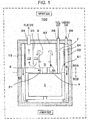
- Fig. 1 illustrates a high-temperature fuel cell system according to the first embodiment.
- a solid oxide fuel cell system (referred to below as a SOFC system 100) including a solid oxide fuel cell (referred to below as a SOFC 1) serving as a power generator is taken as an example of the high-temperature fuel cell system, but the high-temperature fuel cell system is not limited to such.
- the structure of the high-temperature fuel cell system is not limited provided that the high-temperature fuel cell system is a fuel cell system that operates at a high temperature (for example, 600°C or more).
- the high-temperature fuel cell system may be a molten carbonate fuel cell system including a molten carbonate fuel cell (MCFC) serving as a power generator.
- MCFC molten carbonate fuel cell
- Fig. 1 For convenience, the "upper side” and “lower side” of the SOFC system 100 are illustrated in Fig. 1 (and other figures), and the gravity acts from the “upper side” to the “lower side”.
- the SOFC system 100 includes the SOFC 1, a combustion tube 2, a combustion space 3, a combustion chamber 3A, an anode-off-gas path 4, a cathode-off-gas path 5, a fuel-gas path 7, an oxidant-gas path 8, a flue-gas guide 20, a first flue-gas path 11, a second flue-gas path 12, a first heat exchanger 13, a cathode-off-gas branch portion 21, an oxidant-gas supply port 33, a flue-gas outlet 34, and a fuel-gas supply port 36.
- a partition wall 51 is disposed so as to partition the space on the inside of the inner wall 54 of the SOFC system 100 into an upper area 50A in which, for example, the combustion chamber 3A is accommodated and a lower area 50B in which, for example, the SOFC 1 is accommodated.
- the SOFC 1 includes an anode and a cathode and generates power by using a fuel gas and an oxidant gas. Specifically, the SOFC 1 is formed such that multiple single cells of the SOFC 1 that generate power by using an oxidant gas and a fuel gas that are supplied from the outside are, for example, stacked and connected to each other in series.
- the SOFC 1 may be formed of stacked flat plate-shaped single cells or aggregated cylindrical single cells.
- the SOFC 1 of the SOFC system 100 according to the first embodiment is formed of a flat plate-shaped stack of the flat plate-shaped single cells and other components, an example of which is an interconnector.
- the SOFC system 100 includes a temperature sensor (not illustrated) that detects the operating temperature (for example, 600°C or more) of the SOFC 1 and an electrode (not illustrated) through which a generated electric current flows from the SOFC 1 to the outside.
- the structure of the SOFC 1 is the same as the structure of a typical SOFC, and description of the detailed structure thereof is omitted.
- the fuel-gas path 7 is a path along which the fuel gas flows. Specifically, the fuel gas from the fuel-gas supply port 36 passes along the fuel-gas path 7 and is subsequently supplied to the SOFC 1.
- the fuel-gas path 7 extends from the upper wall 52 of the SOFC system 100 to the SOFC 1 through the upper area 50A and the partition wall 51.
- Examples of the fuel gas include a hydrogen gas and a reformed gas. Details of the SOFC system 100 in the case where the fuel gas is a reformed gas are described in a second embodiment.
- the oxidant-gas path 8 is a path along which the oxidant gas flows. Specifically, the oxidant gas from the oxidant-gas supply port 33 passes along the oxidant-gas path 8 and is subsequently supplied to the SOFC 1. Examples of the oxidant gas include air.
- the oxidant-gas path 8 is formed between the outer wall 53 and inner wall 54 of the SOFC system 100.
- the outer wall 53 and the inner wall 54 extend from the upper wall 52 to the lower side of the SOFC 1 and cover the bottom of the SOFC 1. Since the operating temperature of the SOFC system 100 becomes a high temperature (for example, 600°C or more), the SOFC system 100 is typically covered by an insulating material 41 to suppress heat dissipation to the outside.
- the anode-off-gas path 4 is a path along which the anode off-gas discharged from the anode of the SOFC 1 flows. Specifically, a fuel gas (anode off-gas) that is not used for power generation in the SOFC 1 flows to the anode-off-gas path 4, passes along the anode-off-gas path 4, and is subsequently supplied to the combustion space 3 in the combustion chamber 3A.
- a fuel gas anode off-gas
- the cathode-off-gas path 5 is a path along which the cathode off-gas discharged from the cathode of the SOFC 1 flows. Specifically, an oxidant gas (cathode off-gas) that is not used for power generation in the SOFC 1 flows to the cathode-off-gas path 5, passes along the cathode-off-gas path 5, and is subsequently supplied to the combustion space 3 in the combustion chamber 3A.
- the combustion space 3 is in communication with the anode-off-gas path 4 and the cathode-off-gas path 5.
- the anode off-gas and the cathode off-gas are burned in the combustion space 3.
- the anode-off-gas path 4 and the cathode-off-gas path 5 extend from the lower area 50B, in which the SOFC 1 is accommodated, through the partition wall 51 and are connected to the combustion chamber 3A in the upper area 50A.
- a high-temperature flue gas is thus produced in the combustion space 3.
- an igniter and a combustion detector are disposed in the combustion chamber 3A.
- the structure thereof is the same as the structure of those of the combustion chamber of a typical SOFC system, and detailed description and drawings thereof are omitted.
- the first flue-gas path 11 and the second flue-gas path 12 are paths along which the flue gas discharged from the combustion space 3 flows.
- the combustion tube 2 is disposed so as to surround the combustion space 3.
- the combustion tube 2 which is tubular (for example, cylindrical), surrounds the combustion space 3 and extends vertically upward from the combustion chamber 3A around the combustion space 3.
- the combustion tube 2 and the combustion chamber 3A thus form the combustion space 3, in which the anode off-gas and the cathode off-gas are burned by diffusion combustion.
- the flue-gas guide 20 which is tubular (for example, cylindrical), is disposed outside the combustion tube 2 coaxially with the combustion tube 2.
- the flue-gas guide 20 extends vertically downward from the upper wall 52 around the combustion tube 2.
- the lower end of the flue-gas guide 20 is lower than the upper end of the combustion tube 2 and does not impede the flue gas flowing along the first flue-gas path 11.
- the first flue-gas path 11 is thus formed as a space between the combustion tube 2 and the flue-gas guide 20, and the second flue-gas path 12 is formed as a space between the flue-gas guide 20 and the inner wall 54.
- the flue-gas outlet 34 formed in the upper wall 52 is in communication with the second flue-gas path 12. Accordingly, the flue gas in the combustion space 3 is guided upward along the combustion tube 2, subsequently turns at the upper end of the combustion tube 2, and is guided to the first flue-gas path 11.
- the flue gas flowing along the first flue-gas path 11 is guided downward along the flue-gas guide 20, subsequently turns again at the lower end of the flue-gas guide 20, and is guided to the second flue-gas path 12.
- the first heat exchanger 13 enables heat exchange between the oxidant gas flowing along the oxidant-gas path 8 and the flue gas flowing along the second flue-gas path 12. Specifically, at the first heat exchanger 13, part of the inner wall 54 that is exposed to the flue gas flowing along the second flue-gas path 12 functions as a heat-transfer surface. Thus, the oxidant gas having a normal temperature, which is a fluid to be heated of the first heat exchanger 13, is heated, and the flue gas having a high temperature, which is a heating fluid, is cooled and discharged from the flue-gas outlet 34 to the outside of the SOFC system 100. The flue gas discharged to the outside of the SOFC system 100 is supplied to, for example, a heat exchanger, not illustrated, that produces hot water for hot-water supply.
- the cathode-off-gas branch portion 21 is disposed on the cathode-off-gas path 5 between the combustion space 3 and the cathode of the SOFC 1. Some of the cathode off-gas is branched into the outside of the cathode-off-gas path 5.
- the cathode off-gas that has passed through the cathode-off-gas branch portion 21, together with the flue gas, is used as the heating fluid of the first heat exchanger 13. That is, the first heat exchanger 13 enables heat exchange between the oxidant gas flowing along the oxidant-gas path 8 and a mixed gas of the flue gas flowing along the second flue-gas path 12 and the cathode off-gas that has passed through the cathode-off-gas branch portion 21.
- the cathode off-gas that has passed through the cathode-off-gas branch portion 21 be not conducive to the combustion reaction in the combustion space 3 but be mixed with the flue gas near the lower end of the flue-gas guide 20. That is, the cathode off-gas that has passed through the cathode-off-gas branch portion 21 is mixed with the flue gas at a position upstream of the second flue-gas path 12 in the direction in which the flue gas flows. In other words, a mixing portion, at which the cathode off-gas that has passed through the cathode-off-gas branch portion 21 is mixed with the flue gas, is disposed upstream of the second flue-gas path 12.
- the cathode off-gas that has passed through the cathode-off-gas branch portion 21 may be mixed with the flue gas on the first flue-gas path 11 or on the second flue-gas path 12.
- the cathode off-gas that has passed through the cathode-off-gas branch portion 21 and the flue gas flowing along the first flue-gas path 11 or the second flue-gas path 12 are thus mixed together outside the combustion space 3.
- cathode-off-gas branch portion 21 Specific examples of the cathode-off-gas branch portion 21 will be described in the first example and the second example.
- the SOFC system 100 can maintain an operating state better than in conventional fuel cell systems even when the fuel utilization (Uf) is increased to operate the SOFC system 100 with high efficiency.
- an air ratio in the combustion space 3 can be inhibited from becoming excessive during the combustion reaction unlike the case of conventional high-temperature fuel cell systems, even when the fuel utilization (Uf) is increased to operate the SOFC system 100 with high efficiency. Accordingly, the possibility of a misfire in the combustion space 3 and the possibility of the occurrence of high-concentration carbon monoxide in the combustion space 3 can be reduced more than in conventional high-temperature fuel cell systems, and a good combustion state in the combustion space 3 can be maintained.
- the high-temperature cathode off-gas that has passed through the cathode-off-gas branch portion 21 can be effectively used as the heating fluid of the first heat exchanger 13 to pre-heat the oxidant gas to be supplied to the cathode of the SOFC 1.
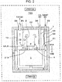
- Fig. 2 and Fig. 3 each illustrate a high-temperature fuel cell system according to the first example of the first embodiment.
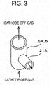
- Fig. 3 is a perspective view of a cathode off-gas pipe 5A and a branch pipe 21A connected to the cathode off-gas pipe 5A that form the cathode-off-gas path 5 according to the first example.
- the cathode-off-gas branch portion 21 of the SOFC system 100 according to the first embodiment is specified as a branch from the cathode-off-gas path 5.
- the branch pipe 21A is disposed as the branch at an appropriate position on the cathode off-gas pipe 5A so as to be in communication with the inside of the cathode off-gas pipe 5A.
- the cathode off-gas pipe 5A is connected to the combustion chamber 3A. Accordingly, the cathode off-gas that has passed through the cathode off-gas pipe 5A is conducive to the combustion reaction in the combustion space 3.
- the branch pipe 21A is not connected to the combustion chamber 3A and extends toward the first flue-gas path 11 outside the combustion tube 2. Accordingly, as illustrated in Fig. 2 , the cathode off-gas that has passed through the branch pipe 21A is not conducive to the combustion reaction in the combustion space 3 but is mixed with the flue gas.
- the flow rate of the cathode off-gas passing through the branch pipe 21A is determined such that an air ratio in the combustion space 3 can be appropriately inhibited from becoming excessive during the combustion reaction even when the fuel utilization (Uf) is increased to operate the SOFC system 100 with high efficiency.
- the flow rate of the cathode off-gas can be adjusted depending on, for example, the length or diameter of the branch pipe 21A.
- the branch pipe 21A is disposed on the cathode off-gas pipe 5A.
- such branch pipes may be disposed on the cathode off-gas pipe 5A.
- cathode off-gas flowing through the cathode off-gas pipe 5A can be readily branched into the outside of the cathode off-gas pipe 5A from the branch pipe 21A.
- the structure of the SOFC system 100 according to the first example may be the same as the SOFC system 100 according to the first embodiment except for the above features.
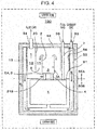
- Fig. 4 and Fig. 5 each illustrate a high-temperature fuel cell system according to the second example of the first embodiment.
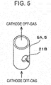
- Fig. 5 is a perspective view of the cathode off-gas pipe 5A and a through-hole 21 B formed in the cathode off-gas pipe 5A that form the cathode-off-gas path 5 according to the second example.
- the cathode-off-gas branch portion 21 of the SOFC system 100 according to the first embodiment is specified as an opening formed on the cathode-off-gas path 5.
- the through-hole 21B is formed as the opening at an appropriate position in the cathode off-gas pipe 5A.
- the cathode off-gas pipe 5A is connected to the combustion chamber 3A. Accordingly, the cathode off-gas that has passed through the cathode off-gas pipe 5A is conducive to the combustion reaction in the combustion space 3.
- the cathode off-gas that has passed through the through-hole 21 B outside the combustion tube 2 is not conducive to the combustion reaction in the combustion space 3 but is mixed with the flue gas.
- the flow rate of the cathode off-gas passing through the through-hole 21 B is determined such that an air ratio in the combustion space 3 can be appropriately inhibited from becoming excessive during the combustion reaction even when the fuel utilization (Uf) is increased to operate the SOFC system 100 with high efficiency.
- the flow rate of the cathode off-gas can be adjusted depending on, for example, the diameter of the through-hole 21 B.
- the through-hole 21 B is formed in the cathode off-gas pipe 5A.
- such through-holes may be formed in the cathode off-gas pipe 5A.
- cathode off-gas flowing through the cathode off-gas pipe 5A can be readily branched into the outside of the cathode off-gas pipe 5A from the through-hole 21 B.
- the through-hole 21 B can be formed more easily than, for example, in the case of disposing the branch on the cathode off-gas pipe 5A.
- the structure of the SOFC system 100 according to the second example may be the same as the SOFC system 100 of the first embodiment except for the above features.
- Fig. 6 illustrates a high-temperature fuel cell system according to the second embodiment.
- the SOFC system 100 includes the SOFC 1, the combustion tube 2, the combustion space 3, the combustion chamber 3A, the anode-off-gas path 4, the cathode-off-gas path 5, the oxidant-gas path 8, a reformed-gas path 9, a reformer 22, the first flue-gas path 11, the second flue-gas path 12, the first heat exchanger 13, a second heat exchanger 14, the cathode-off-gas branch portion 21, a water supply port 32, a source-gas supply port 31, the oxidant-gas supply port 33, and the flue-gas outlet 34.
- the SOFC 1, the combustion tube 2, the combustion space 3, the combustion chamber 3A, the anode-off-gas path 4, the cathode-off-gas path 5, the oxidant-gas path 8, the first heat exchanger 13, the cathode-off-gas branch portion 21, the oxidant-gas supply port 33, and the flue-gas outlet 34 are the same as in the first embodiment, and detailed description thereof is omitted.
- the reformer 22 produces a reformed gas containing hydrogen, as the fuel gas to be supplied to the SOFC 1, from a source gas.
- the reformed gas produced by the reformer 22 flows along the reformed-gas path 9 and is supplied to the SOFC 1.
- the reformer 22 includes an inner tube 22A (for example, a cylindrical body) formed coaxially with the combustion tube 2 with the inner tube 22A surrounding the combustion tube 2, an outer tube 22B (for example, a cylindrical body) formed coaxially with the inner tube 22A with the outer tube 22B surrounding the inner tube 22A, and a reforming catalyst 22C disposed between the inner tube 22A and the outer tube 22B.
- the reformer 22 produces the reformed gas in a manner in which the source gas is reformed by using the reforming catalyst 22C.
- the outer shell of the reformer 22 has a double tube structure including the inner tube 22A, the outer tube 22B, and the bottom.
- the reformed-gas path 9 is connected at an appropriate position to the bottom of the reformer 22.
- the reformed-gas path 9 extends from the bottom of the reformer 22 to the SOFC 1 through the upper area 50A and the partition wall 51.
- the inner tube 22A and the outer tube 22B extend vertically downward from the upper wall 52 around the combustion tube 2.
- the bottom of the reformer 22 is lower than the upper end of the combustion tube 2 and does not impede the flue gas flowing along the first flue-gas path 11.
- the first flue-gas path 11 is thus formed as a space between the combustion tube 2 and the inner tube 22A
- the second flue-gas path 12 is formed as a space between the outer tube 22B and the inner wall 54.
- the flue-gas outlet 34 formed in the upper wall 52 is in communication with the second flue-gas path 12. Accordingly, the flue gas in the combustion space 3 is guided upward along the combustion tube 2, subsequently turns at the upper end of the combustion tube 2, and is guided to the first flue-gas path 11.
- the flue gas flowing along the first flue-gas path 11 is guided downward along the inner tube 22A, subsequently turns again at the bottom of the reformer 22, and is guided to the second flue-gas path 12.
- Reforming reaction in the reformer 22 may be any type of reforming reaction. Examples of the reforming reaction include steam reforming reaction and autothermal reaction. At least one selected from the group consisting of a noble-metal-based catalyst such as Pt, Ru, and Rh and Ni may be typically used as the reforming catalyst 22C.
- a noble-metal-based catalyst such as Pt, Ru, and Rh and Ni
- the reforming reaction in the reformer 22 is steam reforming reaction.
- the reformer 22 includes a vaporizing portion 22D formed of the inner tube 22A and the outer tube 22B above the reforming catalyst 22C. That is, the lower portion of the reformer 22 is filled with the reforming catalyst 22C, and the vaporizing portion 22D is formed at the upper portion of the reformer 22. Water from the water supply port 32 is vaporized at the vaporizing portion 22D, the source gas from the source-gas supply port 31 and steam are mixed together at the vaporizing portion 22D. The mixed gas is supplied to the reforming catalyst 22C.
- the source gas is a gas containing an organic compound including at least carbon and hydrogen such as town gas including methane as a primary component, natural gas, or liquefied petroleum gas (LPG).
- town gas including methane as a primary component, natural gas, or liquefied petroleum gas (LPG).
- the second heat exchanger 14 enables heat exchange between the reformer 22 and the flue gas. Specifically, at the second heat exchanger 14, the outer shell of the reformer 22, in which the reforming catalyst 22C exists, is exposed to the flue gas and functions as the heat-transfer surface. The reforming catalyst 22C in the reformer 22 is thus heated to about 600°C.
- the flue gas flows along the second flue-gas path 12 as the heating fluid of the first heat exchanger 13 and heats the oxidant gas flowing along the oxidant-gas path 8, as described above. At the same time, the flue gas also heats the vaporizing portion 22D in the reformer 22 with the outer tube 22B interposed therebetween.
- the cathode off-gas that has passed through the cathode-off-gas branch portion 21, together with the flue gas, is used as the heating fluid of the second heat exchanger 14.
- the cathode off-gas that has passed through the cathode-off-gas branch portion 21 is not conducive to the combustion reaction in the combustion space 3 but is mixed with the flue gas near the bottom of the reformer 22. That is, the cathode off-gas is mixed with the flue gas at a position upstream of the second flue-gas path 12 in the direction in which the flue gas flows.
- the specific example of the cathode-off-gas branch portion 21 according to the second embodiment may be the branch pipe 21A as in the first example of the first embodiment or the through-hole 21 B as in the second example of the first embodiment. Accordingly, detailed description of the specific example of the cathode-off-gas branch portion 21 is omitted.
- the high-temperature cathode off-gas that has passed through the cathode-off-gas branch portion 21 can be effectively used as the heating fluid of the second heat exchanger 14 to heat the reformer 22.
- an air ratio in the combustion space 3 can be inhibited from becoming excessive during the combustion reaction unlike the case of conventional high-temperature fuel cell systems, even when the fuel utilization (Uf) is increased to operate the SOFC system 100 with high efficiency as in the case of the SOFC system 100 according to the first embodiment. Accordingly, the possibility of a misfire in the combustion space 3 and the possibility of the occurrence of high-concentration carbon monoxide in the combustion space 3 can be reduced more than in conventional high-temperature fuel cell systems, and a good combustion state in the combustion space 3 can be maintained.
- the high-temperature cathode off-gas passing through the cathode-off-gas branch portion 21 can be effectively used as the heating fluid of the first heat exchanger 13 to pre-heat the oxidant gas to be supplied to the cathode of the SOFC 1.
- the structure of the SOFC system 100 according to the second embodiment may be the same as the SOFC system 100 according to the first embodiment except for the above features.
- Fig. 7 illustrates a high-temperature fuel cell system according to the third embodiment.
- the SOFC system 100 includes the SOFC 1, the combustion tube 2, the combustion space 3, the combustion chamber 3A, the oxidant-gas path 8, the reformed-gas path 9, the reformer 22, the first flue-gas path 11, the second flue-gas path 12, the first heat exchanger 13, the second heat exchanger 14, the cathode-off-gas branch portion 21, the water supply port 32, the source-gas supply port 31, the oxidant-gas supply port 33, the flue-gas outlet 34, an anode-off-gas ejecting portion 4A, and a cathode-off-gas gathering portion 5B.
- the SOFC 1, the combustion tube 2, the combustion space 3, the oxidant-gas path 8, the reformed-gas path 9, the reformer 22, the first flue-gas path 11, the second flue-gas path 12, the first heat exchanger 13, the second heat exchanger 14, the water supply port 32, the source-gas supply port 31, the oxidant-gas supply port 33, and the flue-gas outlet 34 are the same as in the second embodiment, and detailed description thereof is omitted.
- the anode-off-gas ejecting portion 4A forms part of the anode-off-gas path and ejects the anode off-gas into the combustion space 3.
- a path 4B extending from the SOFC 1 is connected to the bottom of the anode-off-gas ejecting portion 4A.
- the anode off-gas discharged from the anode of the SOFC 1 flows along the path 4B and is supplied to the anode-off-gas ejecting portion 4A.
- the cathode-off-gas gathering portion 5B forms part of the cathode-off-gas path.
- the cathode off-gas gathers at the cathode-off-gas gathering portion 5B.
- the cathode-off-gas path is formed of the cathode-off-gas gathering portion 5B and a space 5C between the outer shell of the SOFC 1 and the partition wall 51.
- the cathode-off-gas gathering portion 5B is in communication with the space 5C via a communication hole 51A formed in the partition wall 51.
- the cathode-off-gas gathering portion 5B includes a passage member including a tubular (for example, cylindrical) peripheral wall 61 B surrounding the anode-off-gas ejecting portion 4A and a diffuser panel 61A having cathode-off-gas ejection holes through which the cathode off-gas is ejected into the combustion space 3 inside the peripheral wall 61 B. That is, the cathode-off-gas gathering portion 5B surrounds the anode-off-gas ejecting portion 4A.
- the combustion chamber 3A is hollowed so as to be tapered from the combustion tube 2 toward the partition wall 51.
- the hollow forms the combustion space 3 for the anode off-gas and the cathode off-gas.
- the anode-off-gas ejecting portion 4A extends vertically upward with respect to the partition wall 51 at the center of the bottom of the hollow.
- the anode-off-gas ejecting portion 4A is formed in a cylindrical shape with a lid and a bottom.
- Anode off-gas ejection holes are formed at predetermined positions in the side surface of the anode-off-gas ejecting portion 4A.
- the anode-off-gas ejecting portion 4A enables the anode off-gas to be ejected from the anode off-gas ejection holes into the combustion space 3.
- the diffuser panel 61A which enables the cathode off-gas to be ejected, is disposed around the central axis of the anode-off-gas ejecting portion 4A so as to surround the anode-off-gas ejecting portion 4A.
- the diffuser panel 61A forms the sloped surface of the tapered hollow.
- the cathode-off-gas ejection holes are formed so as to face the respective anode off-gas ejection holes.
- the cathode-off-gas branch portion 21 is disposed on the peripheral wall 61 B.
- the specific example of the cathode-off-gas branch portion 21 according to the third embodiment may be the branch pipe 21A as in the first example of the first embodiment or the through-hole 21B as in the second example of the first embodiment. Accordingly, detailed description of the specific example of the cathode-off-gas branch portion 21 is omitted.
- the cathode off-gas gathers at the cathode-off-gas gathering portion 5B since the cathode off-gas gathers at the cathode-off-gas gathering portion 5B, the dispersibility of the cathode off-gas ejected through the diffuser panel 61A can be improved, even when the fuel utilization (Uf) is increased to operate the SOFC system 100 with high efficiency. Since the cathode-off-gas ejection holes and the anode off-gas ejection holes are formed so as to substantially face each other, a jet of the anode off-gas ejected from the anode off-gas ejection holes and a jet of the cathode off-gas ejected from the cathode-off-gas ejection holes collide with each other. This improves miscibility of the cathode off-gas and the anode off-gas in the combustion space 3.
- an air ratio in the combustion space 3 can be inhibited from becoming excessive during the combustion reaction unlike the case of conventional high-temperature fuel cell systems, even when the fuel utilization (Uf) is increased to operate the SOFC system 100 with high efficiency as in the case of the SOFC system 100 according to the first embodiment. Accordingly, the possibility of a misfire in the combustion space 3 and the possibility of the occurrence of high-concentration carbon monoxide in the combustion space 3 can be reduced more than in conventional high-temperature fuel cell systems, and a good combustion state in the combustion space 3 can be maintained.
- the high-temperature cathode off-gas passing through the cathode-off-gas branch portion 21 can be effectively used as the heating fluid of the first heat exchanger 13 and the second heat exchanger 14 to pre-heat the oxidant gas to be supplied to the cathode of the SOFC 1 and to heat the reformer 22 as in the case of the SOFC system 100 according to the second embodiment.
- the structure of the SOFC system 100 according to the third embodiment may be the same as the SOFC system 100 of the second embodiment except for the above features.
- the SOFC system 100 according to the third embodiment corresponds to an example of the SOFC system 100 according to the second embodiment in which the combustion chamber 3A includes the anode-off-gas ejecting portion 4A and the cathode-off-gas gathering portion 5B.
- the SOFC system 100 according to the first embodiment may include the anode-off-gas ejecting portion 4A and the cathode-off-gas gathering portion 5B.
- the high-temperature fuel cell system according to the aspect of the present disclosure can maintain an operating state better than in conventional fuel cell systems even when the fuel utilization (Uf) is increased to operate the high-temperature fuel cell system with high efficiency. Accordingly, the aspect of the present disclosure can be applied to a high-temperature fuel cell system such as a SOFC system.
Landscapes
- Chemical & Material Sciences (AREA)
- Engineering & Computer Science (AREA)
- Chemical Kinetics & Catalysis (AREA)
- Life Sciences & Earth Sciences (AREA)
- Manufacturing & Machinery (AREA)
- Sustainable Development (AREA)
- Sustainable Energy (AREA)
- Electrochemistry (AREA)
- General Chemical & Material Sciences (AREA)
- Combustion & Propulsion (AREA)
- Organic Chemistry (AREA)
- General Health & Medical Sciences (AREA)
- Inorganic Chemistry (AREA)
- Health & Medical Sciences (AREA)
- Fuel Cell (AREA)
- Hydrogen, Water And Hydrids (AREA)
Abstract
Description
- The present disclosure relates to a high-temperature fuel cell system.
- Fuel cell systems have high power generation efficiency even when their size is small and can improve their total efficiency by using heat produced during power generation. Accordingly, fuel cell systems are used as power generators of distributed power generation systems. In particular, solid oxide fuel cells (referred to below as SOFCs), which operate at a high temperature by using a solid oxide as an electrolyte, have been developed as distributed power generation systems emphasizing high power generation efficiency.
- In a fuel cell system, a fuel gas (typically, a reformed gas) and an oxidant gas (typically, air) are supplied to a SOFC for power generation. During power generation in the fuel cell system, some of the fuel gas supplied to an anode is not used for power generation and is discharged from the SOFC as an anode off-gas.
- When the anode off-gas is burned by a burner, a high-temperature flue gas is produced. In many fuel cell systems, the flue gas in the burner is used to heat a reformer for generating a reformed gas. The SOFC operates at, for example, a high temperature of 600°C or more and also generates a high-temperature cathode off-gas.
- In view of this, it is effective for the SOFC to be formed integrally with an air heat exchanger for effective use of waste heat. For example, there is disclosed a system in which a SOFC is disposed at the center of the system, an air heat exchanger is disposed so as to surround the SOFC, and air to be supplied to the cathode of the SOFC is pre-heated (see, for example, Japanese Unexamined Patent Application Publication No.
2013-171636 - In conventional examples, however, problems in the case where fuel utilization (Uf) is increased to operate a high-temperature fuel cell system with high efficiency have not been sufficiently considered. An aspect of the present disclosure has been accomplished in view of such circumstances, and one nonlimiting and exemplary embodiment provides a high-temperature fuel cell system that can maintain an operating state better than in conventional fuel cell systems even when the fuel utilization (Uf) is increased to operate the high-temperature fuel cell system with high efficiency.
- In one general aspect, the techniques disclosed here feature a high-temperature fuel cell system including a fuel cell that includes an anode and a cathode and that generates power by using a fuel gas and an oxidant gas, a fuel-gas path along which the fuel gas flows, an oxidant-gas path along which the oxidant gas flows, an anode-off-gas path along which an anode off-gas discharged from the anode flows, a cathode-off-gas path along which a cathode off-gas discharged from the cathode flows, a combustion space that is in communication with the anode-off-gas path and the cathode-off-gas path and in which the anode off-gas and the cathode off-gas are burned, a flue-gas path along which a flue gas discharged from the combustion space flows, a cathode-off-gas branch portion that is disposed on the cathode-off-gas path between the combustion space and the cathode and at which some of the cathode off-gas is branched from the cathode-off-gas path, and a first heat exchanger that enables heat exchange between the oxidant gas, the flue gas, and the cathode off-gas that has passed through the cathode off-gas branch portion.
- The high-temperature fuel cell system according to the aspect of the present disclosure can maintain an operating state better than in conventional fuel cell systems even when the fuel utilization (Uf) is increased to operate the high-temperature fuel cell system with high efficiency.
- Additional benefits and advantages of the disclosed embodiments will become apparent from the specification and drawings. The benefits and/or advantages may be individually obtained by the various embodiments and features of the specification and drawings, which need not all be provided in order to obtain one or more of such benefits and/or advantages.
-
-
Fig. 1 illustrates a high-temperature fuel cell system according to a first embodiment; -
Fig. 2 illustrates a high-temperature fuel cell system according to a first example of the first embodiment; -
Fig. 3 illustrates the high-temperature fuel cell system according to the first example of the first embodiment; -
Fig. 4 illustrates a high-temperature fuel cell system according to a second example of the first embodiment; -
Fig. 5 illustrates the high-temperature fuel cell system according to the second example of the first embodiment; -
Fig. 6 illustrates a high-temperature fuel cell system according to a second embodiment; and -
Fig. 7 illustrates a high-temperature fuel cell system according to a third embodiment. - The present inventors have diligently considered the problems in the case where the fuel utilization (Uf) is increased to operate a high-temperature fuel cell system with high efficiency and found the following.
- As the fuel utilization (Uf) increases to operate a high-temperature fuel cell system with higher efficiency, the amount of an anode off-gas, which is a fuel supplied to a combustion space, decreases, and a ratio of the anode off-gas to a cathode off-gas decreases. In this state, combustion in the combustion space occurs with a small amount of the fuel, resulting in an excessive air ratio during combustion reaction. Consequently, there is a possibility that problems such as a misfire in the combustion space and an increase in concentration of carbon monoxide in a flue gas occur.
- The present inventors have conceived that the possibility is reduced in a manner in which some of the cathode off-gas is branched before the cathode off-gas is supplied to the combustion space.
- A high-temperature fuel cell system according to a first aspect of the present disclosure includes a fuel cell that includes an anode and a cathode and that generates power by using a fuel gas and an oxidant gas, a fuel-gas path along which the fuel gas flows, an oxidant-gas path along which the oxidant gas flows, an anode-off-gas path along which an anode off-gas discharged from the anode flows, a cathode-off-gas path along which a cathode off-gas discharged from the cathode flows, a combustion space that is in communication with the anode-off-gas path and the cathode-off-gas path and in which the anode off-gas and the cathode off-gas are burned, a flue-gas path along which a flue gas discharged from the combustion space flows, a cathode-off-gas branch portion that is disposed on the cathode-off-gas path between the combustion space and the cathode and at which some of the cathode off-gas is branched from the cathode-off-gas path, and a first heat exchanger that enables heat exchange between the oxidant gas, the flue gas, and the cathode off-gas that has passed through the cathode off-gas branch portion.
- According to a second aspect of the present disclosure, the high-temperature fuel cell system according to the first aspect includes a mixing portion that is disposed on the flue-gas path and at which the flue gas and the cathode off-gas that has passed through the cathode-off-gas branch portion are mixed.
- With this structure, an operating state better than in conventional fuel cell systems can be maintained even when the fuel utilization (Uf) is increased to operate the high-temperature fuel cell system with high efficiency.
- Specifically, since some of the cathode off-gas is branched to the outside of the cathode-off-gas path at the cathode-off-gas branch portion, an air ratio in the combustion space can be inhibited from becoming excessive during the combustion reaction unlike the case of conventional high-temperature fuel cell systems, even when the fuel utilization (Uf) is increased to operate the high-temperature fuel cell system with high efficiency. Accordingly, the possibility of a misfire in the combustion space and the possibility of the occurrence of high-concentration carbon monoxide in the combustion space can be reduced more than in conventional high-temperature fuel cell systems, and a good combustion state in the combustion space can be maintained.
- In addition, a high-temperature cathode off-gas that has passed through the cathode-off-gas branch portion can be effectively used as a heating fluid of the first heat exchanger to pre-heat the oxidant gas to be supplied to the cathode of the fuel cell.
- A first embodiment, a first example and second example of the first embodiment, a second embodiment, and a third embodiment of the present disclosure will hereinafter be described with reference to the drawings. In the following specific examples, for example, components and the position and connection form of the components are described by way of example and do not limit the present disclosure. Among the components in the specific examples, components that are not recited in the independent claim showing the most generic concept of the present disclosure are described as arbitrary components. In the drawings, description of components designated by like symbols is omitted in some cases. In the drawings, each component is schematically illustrated for simplicity, and the shape and dimension thereof are not accurate in some cases.
-
Fig. 1 illustrates a high-temperature fuel cell system according to the first embodiment. - In the following description, a solid oxide fuel cell system (referred to below as a SOFC system 100) including a solid oxide fuel cell (referred to below as a SOFC 1) serving as a power generator is taken as an example of the high-temperature fuel cell system, but the high-temperature fuel cell system is not limited to such. The structure of the high-temperature fuel cell system is not limited provided that the high-temperature fuel cell system is a fuel cell system that operates at a high temperature (for example, 600°C or more). For example, instead of the SOFC
system 100 described below, the high-temperature fuel cell system may be a molten carbonate fuel cell system including a molten carbonate fuel cell (MCFC) serving as a power generator. - For convenience, the "upper side" and "lower side" of the SOFC
system 100 are illustrated inFig. 1 (and other figures), and the gravity acts from the "upper side" to the "lower side". - According to the first embodiment illustrated in
Fig. 1 , theSOFC system 100 includes theSOFC 1, acombustion tube 2, acombustion space 3, acombustion chamber 3A, an anode-off-gas path 4, a cathode-off-gas path 5, a fuel-gas path 7, an oxidant-gas path 8, a flue-gas guide 20, a first flue-gas path 11, a second flue-gas path 12, afirst heat exchanger 13, a cathode-off-gas branch portion 21, an oxidant-gas supply port 33, a flue-gas outlet 34, and a fuel-gas supply port 36. - In the SOFC
system 100 according to the first embodiment, apartition wall 51 is disposed so as to partition the space on the inside of theinner wall 54 of theSOFC system 100 into anupper area 50A in which, for example, thecombustion chamber 3A is accommodated and alower area 50B in which, for example, the SOFC 1 is accommodated. - The SOFC 1 includes an anode and a cathode and generates power by using a fuel gas and an oxidant gas. Specifically, the SOFC 1 is formed such that multiple single cells of the SOFC 1 that generate power by using an oxidant gas and a fuel gas that are supplied from the outside are, for example, stacked and connected to each other in series. The SOFC 1 may be formed of stacked flat plate-shaped single cells or aggregated cylindrical single cells. The SOFC 1 of the SOFC
system 100 according to the first embodiment is formed of a flat plate-shaped stack of the flat plate-shaped single cells and other components, an example of which is an interconnector. The SOFCsystem 100 includes a temperature sensor (not illustrated) that detects the operating temperature (for example, 600°C or more) of the SOFC 1 and an electrode (not illustrated) through which a generated electric current flows from the SOFC 1 to the outside. The structure of the SOFC 1 is the same as the structure of a typical SOFC, and description of the detailed structure thereof is omitted. - The fuel-
gas path 7 is a path along which the fuel gas flows. Specifically, the fuel gas from the fuel-gas supply port 36 passes along the fuel-gas path 7 and is subsequently supplied to the SOFC 1. The fuel-gas path 7 extends from theupper wall 52 of theSOFC system 100 to the SOFC 1 through theupper area 50A and thepartition wall 51. - Examples of the fuel gas include a hydrogen gas and a reformed gas. Details of the
SOFC system 100 in the case where the fuel gas is a reformed gas are described in a second embodiment. - The oxidant-
gas path 8 is a path along which the oxidant gas flows. Specifically, the oxidant gas from the oxidant-gas supply port 33 passes along the oxidant-gas path 8 and is subsequently supplied to theSOFC 1. Examples of the oxidant gas include air. - The oxidant-
gas path 8 is formed between theouter wall 53 andinner wall 54 of theSOFC system 100. Theouter wall 53 and theinner wall 54 extend from theupper wall 52 to the lower side of theSOFC 1 and cover the bottom of theSOFC 1. Since the operating temperature of theSOFC system 100 becomes a high temperature (for example, 600°C or more), theSOFC system 100 is typically covered by an insulatingmaterial 41 to suppress heat dissipation to the outside. - The anode-off-
gas path 4 is a path along which the anode off-gas discharged from the anode of theSOFC 1 flows. Specifically, a fuel gas (anode off-gas) that is not used for power generation in theSOFC 1 flows to the anode-off-gas path 4, passes along the anode-off-gas path 4, and is subsequently supplied to thecombustion space 3 in thecombustion chamber 3A. - The cathode-off-
gas path 5 is a path along which the cathode off-gas discharged from the cathode of theSOFC 1 flows. Specifically, an oxidant gas (cathode off-gas) that is not used for power generation in theSOFC 1 flows to the cathode-off-gas path 5, passes along the cathode-off-gas path 5, and is subsequently supplied to thecombustion space 3 in thecombustion chamber 3A. - The
combustion space 3 is in communication with the anode-off-gas path 4 and the cathode-off-gas path 5. The anode off-gas and the cathode off-gas are burned in thecombustion space 3. Specifically, the anode-off-gas path 4 and the cathode-off-gas path 5 extend from thelower area 50B, in which theSOFC 1 is accommodated, through thepartition wall 51 and are connected to thecombustion chamber 3A in theupper area 50A. - A high-temperature flue gas is thus produced in the
combustion space 3. For example, an igniter and a combustion detector are disposed in thecombustion chamber 3A. The structure thereof is the same as the structure of those of the combustion chamber of a typical SOFC system, and detailed description and drawings thereof are omitted. - The first flue-
gas path 11 and the second flue-gas path 12 are paths along which the flue gas discharged from thecombustion space 3 flows. Thecombustion tube 2 is disposed so as to surround thecombustion space 3. Specifically, thecombustion tube 2, which is tubular (for example, cylindrical), surrounds thecombustion space 3 and extends vertically upward from thecombustion chamber 3A around thecombustion space 3. - The
combustion tube 2 and thecombustion chamber 3A thus form thecombustion space 3, in which the anode off-gas and the cathode off-gas are burned by diffusion combustion. - The flue-
gas guide 20, which is tubular (for example, cylindrical), is disposed outside thecombustion tube 2 coaxially with thecombustion tube 2. In theSOFC system 100 according to the first embodiment, the flue-gas guide 20 extends vertically downward from theupper wall 52 around thecombustion tube 2. The lower end of the flue-gas guide 20 is lower than the upper end of thecombustion tube 2 and does not impede the flue gas flowing along the first flue-gas path 11. - The first flue-
gas path 11 is thus formed as a space between thecombustion tube 2 and the flue-gas guide 20, and the second flue-gas path 12 is formed as a space between the flue-gas guide 20 and theinner wall 54. The flue-gas outlet 34 formed in theupper wall 52 is in communication with the second flue-gas path 12. Accordingly, the flue gas in thecombustion space 3 is guided upward along thecombustion tube 2, subsequently turns at the upper end of thecombustion tube 2, and is guided to the first flue-gas path 11. The flue gas flowing along the first flue-gas path 11 is guided downward along the flue-gas guide 20, subsequently turns again at the lower end of the flue-gas guide 20, and is guided to the second flue-gas path 12. - The
first heat exchanger 13 enables heat exchange between the oxidant gas flowing along the oxidant-gas path 8 and the flue gas flowing along the second flue-gas path 12. Specifically, at thefirst heat exchanger 13, part of theinner wall 54 that is exposed to the flue gas flowing along the second flue-gas path 12 functions as a heat-transfer surface. Thus, the oxidant gas having a normal temperature, which is a fluid to be heated of thefirst heat exchanger 13, is heated, and the flue gas having a high temperature, which is a heating fluid, is cooled and discharged from the flue-gas outlet 34 to the outside of theSOFC system 100. The flue gas discharged to the outside of theSOFC system 100 is supplied to, for example, a heat exchanger, not illustrated, that produces hot water for hot-water supply. - The cathode-off-
gas branch portion 21 is disposed on the cathode-off-gas path 5 between thecombustion space 3 and the cathode of theSOFC 1. Some of the cathode off-gas is branched into the outside of the cathode-off-gas path 5. The cathode off-gas that has passed through the cathode-off-gas branch portion 21, together with the flue gas, is used as the heating fluid of thefirst heat exchanger 13. That is, thefirst heat exchanger 13 enables heat exchange between the oxidant gas flowing along the oxidant-gas path 8 and a mixed gas of the flue gas flowing along the second flue-gas path 12 and the cathode off-gas that has passed through the cathode-off-gas branch portion 21. Specifically, it is preferable that, for example, the cathode off-gas that has passed through the cathode-off-gas branch portion 21 be not conducive to the combustion reaction in thecombustion space 3 but be mixed with the flue gas near the lower end of the flue-gas guide 20. That is, the cathode off-gas that has passed through the cathode-off-gas branch portion 21 is mixed with the flue gas at a position upstream of the second flue-gas path 12 in the direction in which the flue gas flows. In other words, a mixing portion, at which the cathode off-gas that has passed through the cathode-off-gas branch portion 21 is mixed with the flue gas, is disposed upstream of the second flue-gas path 12. The cathode off-gas that has passed through the cathode-off-gas branch portion 21 may be mixed with the flue gas on the first flue-gas path 11 or on the second flue-gas path 12. - The cathode off-gas that has passed through the cathode-off-
gas branch portion 21 and the flue gas flowing along the first flue-gas path 11 or the second flue-gas path 12 are thus mixed together outside thecombustion space 3. - Specific examples of the cathode-off-
gas branch portion 21 will be described in the first example and the second example. - The
SOFC system 100 according to the first embodiment can maintain an operating state better than in conventional fuel cell systems even when the fuel utilization (Uf) is increased to operate theSOFC system 100 with high efficiency. - Specifically, since some of the cathode off-gas is branched into the outside of the cathode-off-
gas path 5 at the cathode-off-gas branch portion 21, an air ratio in thecombustion space 3 can be inhibited from becoming excessive during the combustion reaction unlike the case of conventional high-temperature fuel cell systems, even when the fuel utilization (Uf) is increased to operate theSOFC system 100 with high efficiency. Accordingly, the possibility of a misfire in thecombustion space 3 and the possibility of the occurrence of high-concentration carbon monoxide in thecombustion space 3 can be reduced more than in conventional high-temperature fuel cell systems, and a good combustion state in thecombustion space 3 can be maintained. - In addition, in the
SOFC system 100 according to the first embodiment, the high-temperature cathode off-gas that has passed through the cathode-off-gas branch portion 21 can be effectively used as the heating fluid of thefirst heat exchanger 13 to pre-heat the oxidant gas to be supplied to the cathode of theSOFC 1. -
Fig. 2 andFig. 3 each illustrate a high-temperature fuel cell system according to the first example of the first embodiment.Fig. 3 is a perspective view of a cathode off-gas pipe 5A and abranch pipe 21A connected to the cathode off-gas pipe 5A that form the cathode-off-gas path 5 according to the first example. - According to the first example of the first embodiment, the cathode-off-
gas branch portion 21 of theSOFC system 100 according to the first embodiment is specified as a branch from the cathode-off-gas path 5. - Specifically, the
branch pipe 21A is disposed as the branch at an appropriate position on the cathode off-gas pipe 5A so as to be in communication with the inside of the cathode off-gas pipe 5A. As illustrated inFig. 2 , the cathode off-gas pipe 5A is connected to thecombustion chamber 3A. Accordingly, the cathode off-gas that has passed through the cathode off-gas pipe 5A is conducive to the combustion reaction in thecombustion space 3. Thebranch pipe 21A is not connected to thecombustion chamber 3A and extends toward the first flue-gas path 11 outside thecombustion tube 2. Accordingly, as illustrated inFig. 2 , the cathode off-gas that has passed through thebranch pipe 21A is not conducive to the combustion reaction in thecombustion space 3 but is mixed with the flue gas. - The flow rate of the cathode off-gas passing through the
branch pipe 21A is determined such that an air ratio in thecombustion space 3 can be appropriately inhibited from becoming excessive during the combustion reaction even when the fuel utilization (Uf) is increased to operate theSOFC system 100 with high efficiency. The flow rate of the cathode off-gas can be adjusted depending on, for example, the length or diameter of thebranch pipe 21A. - In the first example, the
branch pipe 21A is disposed on the cathode off-gas pipe 5A. However, such branch pipes may be disposed on the cathode off-gas pipe 5A. - Thus, some of the cathode off-gas flowing through the cathode off-
gas pipe 5A can be readily branched into the outside of the cathode off-gas pipe 5A from thebranch pipe 21A. - The structure of the
SOFC system 100 according to the first example may be the same as theSOFC system 100 according to the first embodiment except for the above features. -
Fig. 4 andFig. 5 each illustrate a high-temperature fuel cell system according to the second example of the first embodiment.Fig. 5 is a perspective view of the cathode off-gas pipe 5A and a through-hole 21 B formed in the cathode off-gas pipe 5A that form the cathode-off-gas path 5 according to the second example. - According to the second example of the first embodiment, the cathode-off-
gas branch portion 21 of theSOFC system 100 according to the first embodiment is specified as an opening formed on the cathode-off-gas path 5. - Specifically, the through-
hole 21B is formed as the opening at an appropriate position in the cathode off-gas pipe 5A. As illustrated inFig. 4 , the cathode off-gas pipe 5A is connected to thecombustion chamber 3A. Accordingly, the cathode off-gas that has passed through the cathode off-gas pipe 5A is conducive to the combustion reaction in thecombustion space 3. As illustrated inFig. 4 , the cathode off-gas that has passed through the through-hole 21 B outside thecombustion tube 2 is not conducive to the combustion reaction in thecombustion space 3 but is mixed with the flue gas. - The flow rate of the cathode off-gas passing through the through-
hole 21 B is determined such that an air ratio in thecombustion space 3 can be appropriately inhibited from becoming excessive during the combustion reaction even when the fuel utilization (Uf) is increased to operate theSOFC system 100 with high efficiency. The flow rate of the cathode off-gas can be adjusted depending on, for example, the diameter of the through-hole 21 B. - In the second example, the through-
hole 21 B is formed in the cathode off-gas pipe 5A. However, such through-holes may be formed in the cathode off-gas pipe 5A. - Thus, some of the cathode off-gas flowing through the cathode off-
gas pipe 5A can be readily branched into the outside of the cathode off-gas pipe 5A from the through-hole 21 B. - The through-
hole 21 B can be formed more easily than, for example, in the case of disposing the branch on the cathode off-gas pipe 5A. - The structure of the
SOFC system 100 according to the second example may be the same as theSOFC system 100 of the first embodiment except for the above features. -
Fig. 6 illustrates a high-temperature fuel cell system according to the second embodiment. - According to the second embodiment illustrated in
Fig. 6 , theSOFC system 100 includes theSOFC 1, thecombustion tube 2, thecombustion space 3, thecombustion chamber 3A, the anode-off-gas path 4, the cathode-off-gas path 5, the oxidant-gas path 8, a reformed-gas path 9, areformer 22, the first flue-gas path 11, the second flue-gas path 12, thefirst heat exchanger 13, asecond heat exchanger 14, the cathode-off-gas branch portion 21, awater supply port 32, a source-gas supply port 31, the oxidant-gas supply port 33, and the flue-gas outlet 34. - The
SOFC 1, thecombustion tube 2, thecombustion space 3, thecombustion chamber 3A, the anode-off-gas path 4, the cathode-off-gas path 5, the oxidant-gas path 8, thefirst heat exchanger 13, the cathode-off-gas branch portion 21, the oxidant-gas supply port 33, and the flue-gas outlet 34 are the same as in the first embodiment, and detailed description thereof is omitted. - The
reformer 22 produces a reformed gas containing hydrogen, as the fuel gas to be supplied to theSOFC 1, from a source gas. The reformed gas produced by thereformer 22 flows along the reformed-gas path 9 and is supplied to theSOFC 1. - Specifically, the
reformer 22 includes aninner tube 22A (for example, a cylindrical body) formed coaxially with thecombustion tube 2 with theinner tube 22A surrounding thecombustion tube 2, anouter tube 22B (for example, a cylindrical body) formed coaxially with theinner tube 22A with theouter tube 22B surrounding theinner tube 22A, and a reforming catalyst 22C disposed between theinner tube 22A and theouter tube 22B. Thereformer 22 produces the reformed gas in a manner in which the source gas is reformed by using the reforming catalyst 22C. The outer shell of thereformer 22 has a double tube structure including theinner tube 22A, theouter tube 22B, and the bottom. The reformed-gas path 9 is connected at an appropriate position to the bottom of thereformer 22. The reformed-gas path 9 extends from the bottom of thereformer 22 to theSOFC 1 through theupper area 50A and thepartition wall 51. - In the
SOFC system 100 according to the second embodiment, theinner tube 22A and theouter tube 22B extend vertically downward from theupper wall 52 around thecombustion tube 2. The bottom of thereformer 22 is lower than the upper end of thecombustion tube 2 and does not impede the flue gas flowing along the first flue-gas path 11. - The first flue-
gas path 11 is thus formed as a space between thecombustion tube 2 and theinner tube 22A, and the second flue-gas path 12 is formed as a space between theouter tube 22B and theinner wall 54. The flue-gas outlet 34 formed in theupper wall 52 is in communication with the second flue-gas path 12. Accordingly, the flue gas in thecombustion space 3 is guided upward along thecombustion tube 2, subsequently turns at the upper end of thecombustion tube 2, and is guided to the first flue-gas path 11. The flue gas flowing along the first flue-gas path 11 is guided downward along theinner tube 22A, subsequently turns again at the bottom of thereformer 22, and is guided to the second flue-gas path 12. - Reforming reaction in the
reformer 22 may be any type of reforming reaction. Examples of the reforming reaction include steam reforming reaction and autothermal reaction. At least one selected from the group consisting of a noble-metal-based catalyst such as Pt, Ru, and Rh and Ni may be typically used as the reforming catalyst 22C. - In the
SOFC system 100 according to the second embodiment, the reforming reaction in thereformer 22 is steam reforming reaction. Accordingly, thereformer 22 includes a vaporizingportion 22D formed of theinner tube 22A and theouter tube 22B above the reforming catalyst 22C. That is, the lower portion of thereformer 22 is filled with the reforming catalyst 22C, and the vaporizingportion 22D is formed at the upper portion of thereformer 22. Water from thewater supply port 32 is vaporized at the vaporizingportion 22D, the source gas from the source-gas supply port 31 and steam are mixed together at the vaporizingportion 22D. The mixed gas is supplied to the reforming catalyst 22C. - The source gas is a gas containing an organic compound including at least carbon and hydrogen such as town gas including methane as a primary component, natural gas, or liquefied petroleum gas (LPG).
- The
second heat exchanger 14 enables heat exchange between thereformer 22 and the flue gas. Specifically, at thesecond heat exchanger 14, the outer shell of thereformer 22, in which the reforming catalyst 22C exists, is exposed to the flue gas and functions as the heat-transfer surface. The reforming catalyst 22C in thereformer 22 is thus heated to about 600°C. The flue gas flows along the second flue-gas path 12 as the heating fluid of thefirst heat exchanger 13 and heats the oxidant gas flowing along the oxidant-gas path 8, as described above. At the same time, the flue gas also heats the vaporizingportion 22D in thereformer 22 with theouter tube 22B interposed therebetween. - In the
SOFC system 100 according to the second embodiment, the cathode off-gas that has passed through the cathode-off-gas branch portion 21, together with the flue gas, is used as the heating fluid of thesecond heat exchanger 14. Specifically, the cathode off-gas that has passed through the cathode-off-gas branch portion 21 is not conducive to the combustion reaction in thecombustion space 3 but is mixed with the flue gas near the bottom of thereformer 22. That is, the cathode off-gas is mixed with the flue gas at a position upstream of the second flue-gas path 12 in the direction in which the flue gas flows. The specific example of the cathode-off-gas branch portion 21 according to the second embodiment may be thebranch pipe 21A as in the first example of the first embodiment or the through-hole 21 B as in the second example of the first embodiment. Accordingly, detailed description of the specific example of the cathode-off-gas branch portion 21 is omitted. - In the
SOFC system 100 according to the second embodiment, the high-temperature cathode off-gas that has passed through the cathode-off-gas branch portion 21 can be effectively used as the heating fluid of thesecond heat exchanger 14 to heat thereformer 22. - In addition, since some of the cathode off-gas is branched to the outside of the cathode-off-
gas path 5 at the cathode-off-gas branch portion 21, an air ratio in thecombustion space 3 can be inhibited from becoming excessive during the combustion reaction unlike the case of conventional high-temperature fuel cell systems, even when the fuel utilization (Uf) is increased to operate theSOFC system 100 with high efficiency as in the case of theSOFC system 100 according to the first embodiment. Accordingly, the possibility of a misfire in thecombustion space 3 and the possibility of the occurrence of high-concentration carbon monoxide in thecombustion space 3 can be reduced more than in conventional high-temperature fuel cell systems, and a good combustion state in thecombustion space 3 can be maintained. Furthermore, the high-temperature cathode off-gas passing through the cathode-off-gas branch portion 21 can be effectively used as the heating fluid of thefirst heat exchanger 13 to pre-heat the oxidant gas to be supplied to the cathode of theSOFC 1. - The structure of the
SOFC system 100 according to the second embodiment may be the same as theSOFC system 100 according to the first embodiment except for the above features. -
Fig. 7 illustrates a high-temperature fuel cell system according to the third embodiment. - According to the third embodiment illustrated in
Fig. 7 , theSOFC system 100 includes theSOFC 1, thecombustion tube 2, thecombustion space 3, thecombustion chamber 3A, the oxidant-gas path 8, the reformed-gas path 9, thereformer 22, the first flue-gas path 11, the second flue-gas path 12, thefirst heat exchanger 13, thesecond heat exchanger 14, the cathode-off-gas branch portion 21, thewater supply port 32, the source-gas supply port 31, the oxidant-gas supply port 33, the flue-gas outlet 34, an anode-off-gas ejecting portion 4A, and a cathode-off-gas gathering portion 5B. - The
SOFC 1, thecombustion tube 2, thecombustion space 3, the oxidant-gas path 8, the reformed-gas path 9, thereformer 22, the first flue-gas path 11, the second flue-gas path 12, thefirst heat exchanger 13, thesecond heat exchanger 14, thewater supply port 32, the source-gas supply port 31, the oxidant-gas supply port 33, and the flue-gas outlet 34 are the same as in the second embodiment, and detailed description thereof is omitted. - The anode-off-gas ejecting portion 4A forms part of the anode-off-gas path and ejects the anode off-gas into the
combustion space 3. Specifically, apath 4B extending from theSOFC 1 is connected to the bottom of the anode-off-gas ejecting portion 4A. The anode off-gas discharged from the anode of theSOFC 1 flows along thepath 4B and is supplied to the anode-off-gas ejecting portion 4A. - The cathode-off-
gas gathering portion 5B forms part of the cathode-off-gas path. The cathode off-gas gathers at the cathode-off-gas gathering portion 5B. Specifically, the cathode-off-gas path is formed of the cathode-off-gas gathering portion 5B and a space 5C between the outer shell of theSOFC 1 and thepartition wall 51. The cathode-off-gas gathering portion 5B is in communication with the space 5C via acommunication hole 51A formed in thepartition wall 51. - The cathode-off-
gas gathering portion 5B includes a passage member including a tubular (for example, cylindrical)peripheral wall 61 B surrounding the anode-off-gas ejecting portion 4A and a diffuser panel 61A having cathode-off-gas ejection holes through which the cathode off-gas is ejected into thecombustion space 3 inside the peripheral wall 61 B. That is, the cathode-off-gas gathering portion 5B surrounds the anode-off-gas ejecting portion 4A. - Specifically, as illustrated in
Fig. 7 , thecombustion chamber 3A is hollowed so as to be tapered from thecombustion tube 2 toward thepartition wall 51. The hollow forms thecombustion space 3 for the anode off-gas and the cathode off-gas. The anode-off-gas ejecting portion 4A extends vertically upward with respect to thepartition wall 51 at the center of the bottom of the hollow. The anode-off-gas ejecting portion 4A is formed in a cylindrical shape with a lid and a bottom. Anode off-gas ejection holes are formed at predetermined positions in the side surface of the anode-off-gas ejecting portion 4A. The anode-off-gas ejecting portion 4A enables the anode off-gas to be ejected from the anode off-gas ejection holes into thecombustion space 3. The diffuser panel 61A, which enables the cathode off-gas to be ejected, is disposed around the central axis of the anode-off-gas ejecting portion 4A so as to surround the anode-off-gas ejecting portion 4A. The diffuser panel 61A forms the sloped surface of the tapered hollow. The cathode-off-gas ejection holes are formed so as to face the respective anode off-gas ejection holes. - The cathode-off-
gas branch portion 21 is disposed on theperipheral wall 61 B. - The specific example of the cathode-off-
gas branch portion 21 according to the third embodiment may be thebranch pipe 21A as in the first example of the first embodiment or the through-hole 21B as in the second example of the first embodiment. Accordingly, detailed description of the specific example of the cathode-off-gas branch portion 21 is omitted. - In the
SOFC system 100 according to the third embodiment, since the cathode off-gas gathers at the cathode-off-gas gathering portion 5B, the dispersibility of the cathode off-gas ejected through the diffuser panel 61A can be improved, even when the fuel utilization (Uf) is increased to operate theSOFC system 100 with high efficiency. Since the cathode-off-gas ejection holes and the anode off-gas ejection holes are formed so as to substantially face each other, a jet of the anode off-gas ejected from the anode off-gas ejection holes and a jet of the cathode off-gas ejected from the cathode-off-gas ejection holes collide with each other. This improves miscibility of the cathode off-gas and the anode off-gas in thecombustion space 3. - In addition, since some of the cathode off-gas is branched to the outside of the cathode-off-
gas gathering portion 5B at the cathode-off-gas branch portion 21, an air ratio in thecombustion space 3 can be inhibited from becoming excessive during the combustion reaction unlike the case of conventional high-temperature fuel cell systems, even when the fuel utilization (Uf) is increased to operate theSOFC system 100 with high efficiency as in the case of theSOFC system 100 according to the first embodiment. Accordingly, the possibility of a misfire in thecombustion space 3 and the possibility of the occurrence of high-concentration carbon monoxide in thecombustion space 3 can be reduced more than in conventional high-temperature fuel cell systems, and a good combustion state in thecombustion space 3 can be maintained. - Furthermore, the high-temperature cathode off-gas passing through the cathode-off-
gas branch portion 21 can be effectively used as the heating fluid of thefirst heat exchanger 13 and thesecond heat exchanger 14 to pre-heat the oxidant gas to be supplied to the cathode of theSOFC 1 and to heat thereformer 22 as in the case of theSOFC system 100 according to the second embodiment. - The structure of the
SOFC system 100 according to the third embodiment may be the same as theSOFC system 100 of the second embodiment except for the above features. - The first embodiment, the first example of the first embodiment, the second example of the first embodiment, the second embodiment, and the third embodiment can be combined with each other unless they exclude each other. For example, the
SOFC system 100 according to the third embodiment corresponds to an example of theSOFC system 100 according to the second embodiment in which thecombustion chamber 3A includes the anode-off-gas ejecting portion 4A and the cathode-off-gas gathering portion 5B. TheSOFC system 100 according to the first embodiment may include the anode-off-gas ejecting portion 4A and the cathode-off-gas gathering portion 5B. - Various modifications and other embodiments of the present disclosure become obvious to a person skilled in the art from the above description. Accordingly, the description should be interpreted as an example and is provided to teach the best mode for carrying out the present disclosure to a person skilled in the art. The detailed structure and/or function of the present disclosure can be substantially modified without departing from the concept of the present disclosure.
- The high-temperature fuel cell system according to the aspect of the present disclosure can maintain an operating state better than in conventional fuel cell systems even when the fuel utilization (Uf) is increased to operate the high-temperature fuel cell system with high efficiency. Accordingly, the aspect of the present disclosure can be applied to a high-temperature fuel cell system such as a SOFC system.
Claims (7)
- A high-temperature fuel cell system comprising:a fuel cell that includes an anode and a cathode and that generates power by using a fuel gas and an oxidant gas;a fuel-gas path along which the fuel gas flows;an oxidant-gas path along which the oxidant gas flows;an anode-off-gas path along which an anode off-gas discharged from the anode flows;a cathode-off-gas path along which a cathode off-gas discharged from the cathode flows;a combustion space that is in communication with the anode-off-gas path and the cathode-off-gas path and in which the anode off-gas and the cathode off-gas are burned;a flue-gas path along which a flue gas discharged from the combustion space flows;a cathode-off-gas branch portion that is disposed on the cathode-off-gas path between the combustion space and the cathode and at which some of the cathode off-gas is branched from the cathode-off-gas path; anda first heat exchanger that enables heat exchange between the oxidant gas, the flue gas, and the cathode off-gas that has passed through the cathode off-gas branch portion.
- The high-temperature fuel cell system according to Claim 1, further comprising:a mixing portion that is disposed on the flue-gas path and at which the flue gas and the cathode off-gas that has passed through the cathode-off-gas branch portion are mixed.
- The high-temperature fuel cell system according to Claim 1, further comprising:a reformer that generates, from a source gas, a reformed gas containing hydrogen used as the fuel gas to be supplied to the fuel cell; anda second heat exchanger that enables heat exchange between the reformer and the flue gas,wherein the cathode off-gas that has passed through the cathode-off-gas branch portion, together with the flue gas, is used as a heating fluid of the second heat exchanger.
- The high-temperature fuel cell system according to Claim 1, further comprising:an anode-off-gas ejecting portion that forms part of the anode-off-gas path and from which the anode off-gas is ejected into the combustion space; anda cathode-off-gas gathering portion that forms part of the cathode-off-gas path and at which the cathode off-gas gathers,wherein the cathode-off-gas gathering portion includes a passage member including a cylindrical peripheral wall surrounding the anode-off-gas ejecting portion and a diffuser panel having a cathode-off-gas ejection hole through which the cathode off-gas is ejected into the combustion space inside the peripheral wall, andwherein the cathode-off-gas branch portion is formed on the peripheral wall.
- The high-temperature fuel cell system according to Claim 1,
wherein the cathode-off-gas branch portion is a branch from the cathode-off-gas path. - The high-temperature fuel cell system according to Claim 1,
wherein the cathode-off-gas branch portion is an opening formed on the cathode-off-gas path. - The high-temperature fuel cell system according to Claim 1, further comprising:a combustion tube and a combustion chamber that define the combustion space,wherein the cathode off-gas that has passed through the cathode-off-gas branch portion and the flue gas passing along the flue-gas path are mixed outside the combustion space.
Applications Claiming Priority (1)
| Application Number | Priority Date | Filing Date | Title |
|---|---|---|---|
| JP2016100266 | 2016-05-19 |
Publications (2)
| Publication Number | Publication Date |
|---|---|
| EP3246977A1 true EP3246977A1 (en) | 2017-11-22 |
| EP3246977B1 EP3246977B1 (en) | 2019-01-02 |
Family
ID=58671527
Family Applications (1)
| Application Number | Title | Priority Date | Filing Date |
|---|---|---|---|
| EP17169723.8A Active EP3246977B1 (en) | 2016-05-19 | 2017-05-05 | High-temperature fuel cell system |
Country Status (3)
| Country | Link |
|---|---|
| US (1) | US10320016B2 (en) |
| EP (1) | EP3246977B1 (en) |
| JP (1) | JP6814970B2 (en) |
Families Citing this family (7)
| Publication number | Priority date | Publication date | Assignee | Title |
|---|---|---|---|---|
| JP7182263B2 (en) * | 2018-03-15 | 2022-12-02 | パナソニックIpマネジメント株式会社 | Solid oxide fuel cell system |
| JP7215032B2 (en) * | 2018-09-17 | 2023-01-31 | 株式会社デンソー | fuel cell device |
| JP7310519B2 (en) * | 2019-10-03 | 2023-07-19 | 株式会社Soken | combustor |
| JP6980045B2 (en) | 2020-01-31 | 2021-12-15 | 三菱パワー株式会社 | Fuel cell power generation system |
| CN111952630B (en) * | 2020-08-13 | 2022-07-19 | 北京理工大学 | Portable fuel cell system and implementation method thereof |
| WO2023126625A1 (en) * | 2021-12-30 | 2023-07-06 | Ceres Intellectual Property Company Limited | Fuel cell system |
| JP7753893B2 (en) * | 2022-01-14 | 2025-10-15 | 株式会社デンソー | fuel cell device |
Citations (5)
| Publication number | Priority date | Publication date | Assignee | Title |
|---|---|---|---|---|
| EP0456848A1 (en) * | 1989-01-09 | 1991-11-21 | Ishikawajima-Harima Heavy Industries Co., Ltd. | Electric power producing system using molten carbonate type fuel cell |
| JP2012153579A (en) * | 2011-01-27 | 2012-08-16 | Panasonic Corp | Hydrogen generation apparatus |
| JP2013171636A (en) | 2012-02-17 | 2013-09-02 | Toto Ltd | Fuel cell device |
| EP2887438A1 (en) * | 2013-12-19 | 2015-06-24 | Panasonic Corporation | Fuel cell system |
| EP2955153A1 (en) * | 2013-03-25 | 2015-12-16 | Sumitomo Precision Products Company Limited | Fuel reformer and fuel cell |
Family Cites Families (5)
| Publication number | Priority date | Publication date | Assignee | Title |
|---|---|---|---|---|
| EP0496011B1 (en) * | 1991-01-21 | 1996-11-06 | Ishikawajima-Harima Heavy Industries Co., Ltd. | Power generation system using molten carbonate fuel cells |
| JP3254671B2 (en) * | 1996-12-27 | 2002-02-12 | 石川島播磨重工業株式会社 | Fuel cell power generator using resholm compressor |
| US6608463B1 (en) * | 2002-06-24 | 2003-08-19 | Delphi Technologies, Inc. | Solid-oxide fuel cell system having an integrated air supply system |
| JP4299868B2 (en) * | 2006-07-28 | 2009-07-22 | クロリンエンジニアズ株式会社 | Hydrogen combustion equipment |
| US20170005348A1 (en) * | 2014-03-19 | 2017-01-05 | Sumitomo Precision Products Co., Ltd. | Combustor and fuel cell system |
-
2017
- 2017-04-24 JP JP2017085149A patent/JP6814970B2/en active Active
- 2017-05-05 EP EP17169723.8A patent/EP3246977B1/en active Active
- 2017-05-09 US US15/590,859 patent/US10320016B2/en active Active
Patent Citations (5)
| Publication number | Priority date | Publication date | Assignee | Title |
|---|---|---|---|---|
| EP0456848A1 (en) * | 1989-01-09 | 1991-11-21 | Ishikawajima-Harima Heavy Industries Co., Ltd. | Electric power producing system using molten carbonate type fuel cell |
| JP2012153579A (en) * | 2011-01-27 | 2012-08-16 | Panasonic Corp | Hydrogen generation apparatus |
| JP2013171636A (en) | 2012-02-17 | 2013-09-02 | Toto Ltd | Fuel cell device |
| EP2955153A1 (en) * | 2013-03-25 | 2015-12-16 | Sumitomo Precision Products Company Limited | Fuel reformer and fuel cell |
| EP2887438A1 (en) * | 2013-12-19 | 2015-06-24 | Panasonic Corporation | Fuel cell system |
Also Published As
| Publication number | Publication date |
|---|---|
| EP3246977B1 (en) | 2019-01-02 |
| JP6814970B2 (en) | 2021-01-20 |
| US10320016B2 (en) | 2019-06-11 |
| JP2017212204A (en) | 2017-11-30 |
| US20170338505A1 (en) | 2017-11-23 |
Similar Documents
| Publication | Publication Date | Title |
|---|---|---|
| EP3246977B1 (en) | High-temperature fuel cell system | |
| EP3246976B1 (en) | High-temperature fuel cell system | |
| EP3208878B1 (en) | High-temperature operating fuel-cell module | |
| EP3136487B1 (en) | Hydrogen generating apparatus and fuel cell system | |
| JP6280470B2 (en) | Fuel cell module | |
| CN111989808B (en) | fuel cell system | |
| JP6617925B2 (en) | Fuel cell system | |
| US11050067B2 (en) | Fuel cell system | |
| JP5643711B2 (en) | Fuel cell module | |
| JP6374273B2 (en) | Fuel cell module | |
| JP2015503209A (en) | Humidification heat exchanger for fuel cells | |
| KR101421355B1 (en) | Fuel humidifier | |
| JP5810006B2 (en) | Fuel processing system and combustion apparatus for fuel cell | |
| JP4696495B2 (en) | Fuel cell power generator | |
| EP4620906A1 (en) | Fuel cell reformer and fuel cell system including same | |
| JP6628084B2 (en) | Solid oxide fuel cell device | |
| KR101387856B1 (en) | Plate type steam reformer for solid oxide fuel cell using natural gas | |
| JPWO2012090865A1 (en) | Desulfurization apparatus and fuel cell system | |
| JP2012221934A (en) | Fuel cell module | |
| JP2013026132A (en) | Fuel cell module | |
| JPWO2012090864A1 (en) | Desulfurization apparatus and fuel cell system |
Legal Events
| Date | Code | Title | Description |
|---|---|---|---|
| PUAI | Public reference made under article 153(3) epc to a published international application that has entered the european phase |
Free format text: ORIGINAL CODE: 0009012 |
|
| STAA | Information on the status of an ep patent application or granted ep patent |
Free format text: STATUS: THE APPLICATION HAS BEEN PUBLISHED |
|
| AK | Designated contracting states |
Kind code of ref document: A1 Designated state(s): AL AT BE BG CH CY CZ DE DK EE ES FI FR GB GR HR HU IE IS IT LI LT LU LV MC MK MT NL NO PL PT RO RS SE SI SK SM TR |
|
| AX | Request for extension of the european patent |
Extension state: BA ME |
|
| STAA | Information on the status of an ep patent application or granted ep patent |
Free format text: STATUS: REQUEST FOR EXAMINATION WAS MADE |
|
| 17P | Request for examination filed |
Effective date: 20180516 |
|
| RBV | Designated contracting states (corrected) |
Designated state(s): AL AT BE BG CH CY CZ DE DK EE ES FI FR GB GR HR HU IE IS IT LI LT LU LV MC MK MT NL NO PL PT RO RS SE SI SK SM TR |
|
| GRAP | Despatch of communication of intention to grant a patent |
Free format text: ORIGINAL CODE: EPIDOSNIGR1 |
|
| STAA | Information on the status of an ep patent application or granted ep patent |
Free format text: STATUS: GRANT OF PATENT IS INTENDED |
|
| RIC1 | Information provided on ipc code assigned before grant |
Ipc: H01M 8/0612 20160101ALI20180626BHEP Ipc: H01M 8/124 20160101ALN20180626BHEP Ipc: H01M 8/04014 20160101ALI20180626BHEP Ipc: H01M 8/0662 20160101AFI20180626BHEP |
|
| INTG | Intention to grant announced |
Effective date: 20180801 |
|
| GRAS | Grant fee paid |
Free format text: ORIGINAL CODE: EPIDOSNIGR3 |
|
| GRAA | (expected) grant |
Free format text: ORIGINAL CODE: 0009210 |
|
| STAA | Information on the status of an ep patent application or granted ep patent |
Free format text: STATUS: THE PATENT HAS BEEN GRANTED |
|
| AK | Designated contracting states |
Kind code of ref document: B1 Designated state(s): AL AT BE BG CH CY CZ DE DK EE ES FI FR GB GR HR HU IE IS IT LI LT LU LV MC MK MT NL NO PL PT RO RS SE SI SK SM TR |
|
| REG | Reference to a national code |
Ref country code: GB Ref legal event code: FG4D |
|
| REG | Reference to a national code |
Ref country code: CH Ref legal event code: EP Ref country code: AT Ref legal event code: REF Ref document number: 1085556 Country of ref document: AT Kind code of ref document: T Effective date: 20190115 |
|
| REG | Reference to a national code |
Ref country code: IE Ref legal event code: FG4D |
|
| REG | Reference to a national code |
Ref country code: DE Ref legal event code: R096 Ref document number: 602017001645 Country of ref document: DE |
|
| REG | Reference to a national code |
Ref country code: NL Ref legal event code: MP Effective date: 20190102 |
|
| REG | Reference to a national code |
Ref country code: LT Ref legal event code: MG4D |
|
| REG | Reference to a national code |
Ref country code: AT Ref legal event code: MK05 Ref document number: 1085556 Country of ref document: AT Kind code of ref document: T Effective date: 20190102 |
|
| PG25 | Lapsed in a contracting state [announced via postgrant information from national office to epo] |
Ref country code: NL Free format text: LAPSE BECAUSE OF FAILURE TO SUBMIT A TRANSLATION OF THE DESCRIPTION OR TO PAY THE FEE WITHIN THE PRESCRIBED TIME-LIMIT Effective date: 20190102 |
|
| PG25 | Lapsed in a contracting state [announced via postgrant information from national office to epo] |
Ref country code: SE Free format text: LAPSE BECAUSE OF FAILURE TO SUBMIT A TRANSLATION OF THE DESCRIPTION OR TO PAY THE FEE WITHIN THE PRESCRIBED TIME-LIMIT Effective date: 20190102 Ref country code: PL Free format text: LAPSE BECAUSE OF FAILURE TO SUBMIT A TRANSLATION OF THE DESCRIPTION OR TO PAY THE FEE WITHIN THE PRESCRIBED TIME-LIMIT Effective date: 20190102 Ref country code: NO Free format text: LAPSE BECAUSE OF FAILURE TO SUBMIT A TRANSLATION OF THE DESCRIPTION OR TO PAY THE FEE WITHIN THE PRESCRIBED TIME-LIMIT Effective date: 20190402 Ref country code: FI Free format text: LAPSE BECAUSE OF FAILURE TO SUBMIT A TRANSLATION OF THE DESCRIPTION OR TO PAY THE FEE WITHIN THE PRESCRIBED TIME-LIMIT Effective date: 20190102 Ref country code: PT Free format text: LAPSE BECAUSE OF FAILURE TO SUBMIT A TRANSLATION OF THE DESCRIPTION OR TO PAY THE FEE WITHIN THE PRESCRIBED TIME-LIMIT Effective date: 20190502 Ref country code: ES Free format text: LAPSE BECAUSE OF FAILURE TO SUBMIT A TRANSLATION OF THE DESCRIPTION OR TO PAY THE FEE WITHIN THE PRESCRIBED TIME-LIMIT Effective date: 20190102 Ref country code: LT Free format text: LAPSE BECAUSE OF FAILURE TO SUBMIT A TRANSLATION OF THE DESCRIPTION OR TO PAY THE FEE WITHIN THE PRESCRIBED TIME-LIMIT Effective date: 20190102 |
|
| PG25 | Lapsed in a contracting state [announced via postgrant information from national office to epo] |
Ref country code: IS Free format text: LAPSE BECAUSE OF FAILURE TO SUBMIT A TRANSLATION OF THE DESCRIPTION OR TO PAY THE FEE WITHIN THE PRESCRIBED TIME-LIMIT Effective date: 20190502 Ref country code: GR Free format text: LAPSE BECAUSE OF FAILURE TO SUBMIT A TRANSLATION OF THE DESCRIPTION OR TO PAY THE FEE WITHIN THE PRESCRIBED TIME-LIMIT Effective date: 20190403 Ref country code: HR Free format text: LAPSE BECAUSE OF FAILURE TO SUBMIT A TRANSLATION OF THE DESCRIPTION OR TO PAY THE FEE WITHIN THE PRESCRIBED TIME-LIMIT Effective date: 20190102 Ref country code: LV Free format text: LAPSE BECAUSE OF FAILURE TO SUBMIT A TRANSLATION OF THE DESCRIPTION OR TO PAY THE FEE WITHIN THE PRESCRIBED TIME-LIMIT Effective date: 20190102 Ref country code: BG Free format text: LAPSE BECAUSE OF FAILURE TO SUBMIT A TRANSLATION OF THE DESCRIPTION OR TO PAY THE FEE WITHIN THE PRESCRIBED TIME-LIMIT Effective date: 20190402 Ref country code: RS Free format text: LAPSE BECAUSE OF FAILURE TO SUBMIT A TRANSLATION OF THE DESCRIPTION OR TO PAY THE FEE WITHIN THE PRESCRIBED TIME-LIMIT Effective date: 20190102 |
|
| REG | Reference to a national code |
Ref country code: DE Ref legal event code: R097 Ref document number: 602017001645 Country of ref document: DE |
|
| PG25 | Lapsed in a contracting state [announced via postgrant information from national office to epo] |
Ref country code: AL Free format text: LAPSE BECAUSE OF FAILURE TO SUBMIT A TRANSLATION OF THE DESCRIPTION OR TO PAY THE FEE WITHIN THE PRESCRIBED TIME-LIMIT Effective date: 20190102 Ref country code: IT Free format text: LAPSE BECAUSE OF FAILURE TO SUBMIT A TRANSLATION OF THE DESCRIPTION OR TO PAY THE FEE WITHIN THE PRESCRIBED TIME-LIMIT Effective date: 20190102 Ref country code: RO Free format text: LAPSE BECAUSE OF FAILURE TO SUBMIT A TRANSLATION OF THE DESCRIPTION OR TO PAY THE FEE WITHIN THE PRESCRIBED TIME-LIMIT Effective date: 20190102 Ref country code: AT Free format text: LAPSE BECAUSE OF FAILURE TO SUBMIT A TRANSLATION OF THE DESCRIPTION OR TO PAY THE FEE WITHIN THE PRESCRIBED TIME-LIMIT Effective date: 20190102 Ref country code: CZ Free format text: LAPSE BECAUSE OF FAILURE TO SUBMIT A TRANSLATION OF THE DESCRIPTION OR TO PAY THE FEE WITHIN THE PRESCRIBED TIME-LIMIT Effective date: 20190102 Ref country code: EE Free format text: LAPSE BECAUSE OF FAILURE TO SUBMIT A TRANSLATION OF THE DESCRIPTION OR TO PAY THE FEE WITHIN THE PRESCRIBED TIME-LIMIT Effective date: 20190102 Ref country code: DK Free format text: LAPSE BECAUSE OF FAILURE TO SUBMIT A TRANSLATION OF THE DESCRIPTION OR TO PAY THE FEE WITHIN THE PRESCRIBED TIME-LIMIT Effective date: 20190102 Ref country code: SK Free format text: LAPSE BECAUSE OF FAILURE TO SUBMIT A TRANSLATION OF THE DESCRIPTION OR TO PAY THE FEE WITHIN THE PRESCRIBED TIME-LIMIT Effective date: 20190102 |
|
| PLBE | No opposition filed within time limit |
Free format text: ORIGINAL CODE: 0009261 |
|
| STAA | Information on the status of an ep patent application or granted ep patent |
Free format text: STATUS: NO OPPOSITION FILED WITHIN TIME LIMIT |
|
| PG25 | Lapsed in a contracting state [announced via postgrant information from national office to epo] |
Ref country code: SM Free format text: LAPSE BECAUSE OF FAILURE TO SUBMIT A TRANSLATION OF THE DESCRIPTION OR TO PAY THE FEE WITHIN THE PRESCRIBED TIME-LIMIT Effective date: 20190102 |
|
| 26N | No opposition filed |
Effective date: 20191003 |
|
| PG25 | Lapsed in a contracting state [announced via postgrant information from national office to epo] |
Ref country code: MC Free format text: LAPSE BECAUSE OF FAILURE TO SUBMIT A TRANSLATION OF THE DESCRIPTION OR TO PAY THE FEE WITHIN THE PRESCRIBED TIME-LIMIT Effective date: 20190102 |
|
| REG | Reference to a national code |
Ref country code: BE Ref legal event code: MM Effective date: 20190531 |
|
| PG25 | Lapsed in a contracting state [announced via postgrant information from national office to epo] |
Ref country code: SI Free format text: LAPSE BECAUSE OF FAILURE TO SUBMIT A TRANSLATION OF THE DESCRIPTION OR TO PAY THE FEE WITHIN THE PRESCRIBED TIME-LIMIT Effective date: 20190102 Ref country code: LU Free format text: LAPSE BECAUSE OF NON-PAYMENT OF DUE FEES Effective date: 20190505 |
|
| PG25 | Lapsed in a contracting state [announced via postgrant information from national office to epo] |
Ref country code: TR Free format text: LAPSE BECAUSE OF FAILURE TO SUBMIT A TRANSLATION OF THE DESCRIPTION OR TO PAY THE FEE WITHIN THE PRESCRIBED TIME-LIMIT Effective date: 20190102 |
|
| PG25 | Lapsed in a contracting state [announced via postgrant information from national office to epo] |
Ref country code: IE Free format text: LAPSE BECAUSE OF NON-PAYMENT OF DUE FEES Effective date: 20190505 |
|
| PG25 | Lapsed in a contracting state [announced via postgrant information from national office to epo] |
Ref country code: BE Free format text: LAPSE BECAUSE OF NON-PAYMENT OF DUE FEES Effective date: 20190531 |
|
| PG25 | Lapsed in a contracting state [announced via postgrant information from national office to epo] |
Ref country code: FR Free format text: LAPSE BECAUSE OF NON-PAYMENT OF DUE FEES Effective date: 20190531 |
|
| PG25 | Lapsed in a contracting state [announced via postgrant information from national office to epo] |
Ref country code: CH Free format text: LAPSE BECAUSE OF NON-PAYMENT OF DUE FEES Effective date: 20200531 Ref country code: LI Free format text: LAPSE BECAUSE OF NON-PAYMENT OF DUE FEES Effective date: 20200531 |
|
| PG25 | Lapsed in a contracting state [announced via postgrant information from national office to epo] |
Ref country code: CY Free format text: LAPSE BECAUSE OF FAILURE TO SUBMIT A TRANSLATION OF THE DESCRIPTION OR TO PAY THE FEE WITHIN THE PRESCRIBED TIME-LIMIT Effective date: 20190102 |
|
| PG25 | Lapsed in a contracting state [announced via postgrant information from national office to epo] |
Ref country code: MT Free format text: LAPSE BECAUSE OF FAILURE TO SUBMIT A TRANSLATION OF THE DESCRIPTION OR TO PAY THE FEE WITHIN THE PRESCRIBED TIME-LIMIT Effective date: 20190102 Ref country code: HU Free format text: LAPSE BECAUSE OF FAILURE TO SUBMIT A TRANSLATION OF THE DESCRIPTION OR TO PAY THE FEE WITHIN THE PRESCRIBED TIME-LIMIT; INVALID AB INITIO Effective date: 20170505 |
|
| GBPC | Gb: european patent ceased through non-payment of renewal fee |
Effective date: 20210505 |
|
| PG25 | Lapsed in a contracting state [announced via postgrant information from national office to epo] |
Ref country code: GB Free format text: LAPSE BECAUSE OF NON-PAYMENT OF DUE FEES Effective date: 20210505 |
|
| PG25 | Lapsed in a contracting state [announced via postgrant information from national office to epo] |
Ref country code: MK Free format text: LAPSE BECAUSE OF FAILURE TO SUBMIT A TRANSLATION OF THE DESCRIPTION OR TO PAY THE FEE WITHIN THE PRESCRIBED TIME-LIMIT Effective date: 20190102 |
|
| PGFP | Annual fee paid to national office [announced via postgrant information from national office to epo] |
Ref country code: DE Payment date: 20250521 Year of fee payment: 9 |