EP3246793A1 - Virtual reality display - Google Patents
Virtual reality display Download PDFInfo
- Publication number
- EP3246793A1 EP3246793A1 EP17171688.9A EP17171688A EP3246793A1 EP 3246793 A1 EP3246793 A1 EP 3246793A1 EP 17171688 A EP17171688 A EP 17171688A EP 3246793 A1 EP3246793 A1 EP 3246793A1
- Authority
- EP
- European Patent Office
- Prior art keywords
- sub
- event
- sector
- user
- video data
- Prior art date
- Legal status (The legal status is an assumption and is not a legal conclusion. Google has not performed a legal analysis and makes no representation as to the accuracy of the status listed.)
- Withdrawn
Links
Images






Classifications
-
- G—PHYSICS
- G06—COMPUTING OR CALCULATING; COUNTING
- G06F—ELECTRIC DIGITAL DATA PROCESSING
- G06F3/00—Input arrangements for transferring data to be processed into a form capable of being handled by the computer; Output arrangements for transferring data from processing unit to output unit, e.g. interface arrangements
- G06F3/01—Input arrangements or combined input and output arrangements for interaction between user and computer
- G06F3/011—Arrangements for interaction with the human body, e.g. for user immersion in virtual reality
-
- G—PHYSICS
- G06—COMPUTING OR CALCULATING; COUNTING
- G06T—IMAGE DATA PROCESSING OR GENERATION, IN GENERAL
- G06T11/00—Two-dimensional [2D] image generation
- G06T11/60—Creating or editing images; Combining images with text
-
- G—PHYSICS
- G06—COMPUTING OR CALCULATING; COUNTING
- G06F—ELECTRIC DIGITAL DATA PROCESSING
- G06F3/00—Input arrangements for transferring data to be processed into a form capable of being handled by the computer; Output arrangements for transferring data from processing unit to output unit, e.g. interface arrangements
- G06F3/01—Input arrangements or combined input and output arrangements for interaction between user and computer
- G06F3/011—Arrangements for interaction with the human body, e.g. for user immersion in virtual reality
- G06F3/013—Eye tracking input arrangements
-
- G—PHYSICS
- G06—COMPUTING OR CALCULATING; COUNTING
- G06V—IMAGE OR VIDEO RECOGNITION OR UNDERSTANDING
- G06V20/00—Scenes; Scene-specific elements
- G06V20/40—Scenes; Scene-specific elements in video content
-
- G—PHYSICS
- G06—COMPUTING OR CALCULATING; COUNTING
- G06F—ELECTRIC DIGITAL DATA PROCESSING
- G06F3/00—Input arrangements for transferring data to be processed into a form capable of being handled by the computer; Output arrangements for transferring data from processing unit to output unit, e.g. interface arrangements
- G06F3/01—Input arrangements or combined input and output arrangements for interaction between user and computer
- G06F3/011—Arrangements for interaction with the human body, e.g. for user immersion in virtual reality
- G06F3/012—Head tracking input arrangements
-
- G—PHYSICS
- G06—COMPUTING OR CALCULATING; COUNTING
- G06F—ELECTRIC DIGITAL DATA PROCESSING
- G06F3/00—Input arrangements for transferring data to be processed into a form capable of being handled by the computer; Output arrangements for transferring data from processing unit to output unit, e.g. interface arrangements
- G06F3/01—Input arrangements or combined input and output arrangements for interaction between user and computer
- G06F3/048—Interaction techniques based on graphical user interfaces [GUI]
- G06F3/0484—Interaction techniques based on graphical user interfaces [GUI] for the control of specific functions or operations, e.g. selecting or manipulating an object, an image or a displayed text element, setting a parameter value or selecting a range
- G06F3/04842—Selection of displayed objects or displayed text elements
-
- G—PHYSICS
- G06—COMPUTING OR CALCULATING; COUNTING
- G06T—IMAGE DATA PROCESSING OR GENERATION, IN GENERAL
- G06T2210/00—Indexing scheme for image generation or computer graphics
- G06T2210/22—Cropping
-
- G—PHYSICS
- G06—COMPUTING OR CALCULATING; COUNTING
- G06V—IMAGE OR VIDEO RECOGNITION OR UNDERSTANDING
- G06V20/00—Scenes; Scene-specific elements
- G06V20/40—Scenes; Scene-specific elements in video content
- G06V20/44—Event detection
Definitions
- This specification relates generally to a method and system for virtual reality display, particularly virtual reality display in which events occurring out of a user's viewing area are notified in the viewing area.
- Virtual reality is an immersive form of multimedia which involves displaying a virtual world within a user device, which is typically a headset worn by the user which has two screens (one for each eye) displaying part of the virtual world dependent on the position and/or orientation of the user detected using sensors. Headphones are also usually provided in the headset providing audio and thereby augmenting the virtual experience.
- the virtual world may be computer generated from a real world space captured using a suitable camera system comprising multiple camera sensors oriented in respective directions, typically capturing a 360 degree view field.
- Nokia's OZO (RTM) camera is one such device, providing both spatial video and audio signals for processing and rendering using suitable virtual reality software on a computer system.
- Sensor signals received from the headset are used by the computer system to determine the spatial location and eye orientation of the user within the virtual space, and therefore a view sector to display to the screens.
- the view sector will be a limited angle, less than the full view field and leaves one or more non-viewed sectors within which events may occur.
- the virtual world may be delivered by a live feed from the camera in a real world space, or may be stored in advance.
- Events occurring within a non-viewed sector of the virtual world may be of interest to the user. However, the user is required to turn their head away from the viewed sector to view this event, which may actually be less interesting or important than the event they were originally viewing.
- a method comprises: providing video data representing at least part of virtual space to a user for viewing; identifying a current viewed sector of the virtual space based on user position; determining a sub-portion of said viewing sector; identifying an event occurring in a non-viewed sector of the virtual space; and displaying content indicative of the event in the sub-portion of said current viewing sector.
- the displaying step may comprise displaying a graphical notification of the event in the sub-portion.
- the displaying step may comprise displaying video data showing the event in the sub-portion.
- the step of determining the sub-portion may comprise receiving manual selection through a user interface.
- the step of determining the sub-portion may be performed automatically using image or video attributes within the viewed sector.
- the step of determining the sub-portion may use predefined rules to identify substantially static and/or uniform graphical areas within the viewed sector.
- Multiple possible sub-portions may be identified and ranked using the predefined rules, and wherein the method further comprises selecting a sub-portion based on rank.
- the method may further comprise detecting a focal area within the current viewed sector and wherein the sub-portion is determined to be outside of the focal area.
- the step of detecting the focal area may be based on the detected gaze direction of the user.
- a trained model may be used to determine the sub-portion.
- the step of identifying the event may comprise receiving manual selection through a user interface.
- the step of identifying the event may be performed automatically using predefined rules.
- the step of identifying the event may be performed automatically using a trained model.
- the trained model may use a convolutional neural network and a recurrent neural network.
- the non-viewed sector may be divided into multiple sub-sectors and each is analysed individually to identify an event.
- the method may further comprise receiving video data corresponding to different spatial crop areas of the non-viewed sector(s) and wherein if the identified event occurs within multiple crop areas, the displaying step displays video data from the smallest crop area.
- the video data showing the identified event may be substantially kept the same size when displayed.
- the video data showing the identified event may be transformed in correspondence to the sub-portion.
- the video data showing the identified event may be transformed from a three-dimensional or polar representation to a two-dimensional representation.
- a computer program comprising instructions that when executed by a computer apparatus control it to perform the method.
- a non-transitory computer-readable storage medium having stored thereon computer-readable code, which, when executed by at least one processor, causes the at least one processor to perform a method, comprising: providing video data representing at least part of a virtual space to a user for viewing; identifying a current viewed sector of the virtual space based on user position; determining a sub-portion of said viewing sector; identifying an event occurring in a non-viewed sector of the virtual space; and displaying content indicative of the event in the sub-portion of said current viewing sector.
- an apparatus having at least one processor and at least one memory having computer-readable code stored thereon which when executed controls the at least one processor of an audio capture apparatus: to provide video data representing at least part of a virtual space to a user for viewing; to identify a current viewed sector of the virtual space based on user position; to determine a sub-portion of said viewing sector; to identify an event occurring in a non-viewed sector of the virtual space; and to display content indicative of the event in the sub-portion of said current viewing sector.
- the apparatus may be further configured to perform the above embodiments of the method.
- an apparatus comprising means for providing video data representing at least part of a virtual space to a user for viewing; means for identifying a current viewed sector of the virtual space based on user position; means for determining a sub-portion of said viewing sector; means for identifying an event occurring in a non-viewed sector of the virtual space; and means for displaying content indicative of the event in the sub-portion of said current viewing sector.
- the apparatus may further comprise means for performing the above embodiments of the method.
- Embodiments herein relate to virtual reality (VR) methods and systems, in which a user is provided with a live or stored video feed representing a virtual space. Spatial audio may also be provided.
- VR virtual reality
- a virtual space is any computer generated version of a space, for example a captured real world space, in which a user can be immersed through a visual interface device such as a VR headset.
- a live feed may be provided by a VR system that receives a current version of a real world space from one or more cameras in said space, such as the abovementioned OZO camera which incorporates multiple video sensors.
- the virtual space is stored on memory of the VR system and possibly pre or post -processed by user interaction through a user interface of the system prior to delivery to the user.
- the VR headset incorporates motion tracking sensors which may include gyroscopes, accelerometers and structured light systems. These sensors generate the position data from which the current viewing field, or sector, is determined and updated as the user changes position.
- the VR headset will typically comprise two digital screens for displaying stereoscopic video images of the virtual world in front of respective eyes of the user, and also two speakers for delivering audio, if provided from the VR system.
- the embodiments herein, which primarily relate to the delivery of VR content, are not limited to a particular type of VR headset.
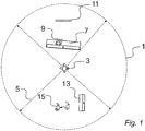
- FIG. 1 an example of capturing VR video content is shown in relation to a real world space 1 shown in top plan view.
- a camera system 3 which may be multiple cameras or Nokia's OZO system, which captures in real-time video with a horizontal, 360 degree field-of-view, indicated generally by arrows 5.
- a 360 degree field-of-view may be captured to create a complete spherical world, or alternatively, a more limited angle may be used.
- various objects including a sofa 7 on which is seated a first person 9.
- a television 11 Spatially behind the sofa 7 is a second sofa 13 and a second person 15 who may or may not be moving.
- a VR processing and rendering system 20 (hereafter referred to simply as the VR system) is shown in relation to the camera 3 for generating a virtual space 22 displayed in computer-generated form within a VR headset 24.
- the VR system 20 receives from the camera 3 video and audio data and generates the virtual space 22 in data form ready for display to the VR headset 24.
- the VR system 20 receives from the VR headset 24 position data, and responsive thereto delivers to the headset video and audio data corresponding to a limited spatial sector of the virtual space which the user is currently looking at.
- a sector refers to any sub-portion of the available spatial field, in this case less than 360 degrees and more likely to be in the order of 70 - 100 degrees.
- a different sector of the available spatial field is delivered in real time or near real time.
- the different sector may overlap with a previous sector.
- Reference to position and position data refers to any parameter indicative of user positioning and/or orientation within the virtual space which can be used to determine what sector the user views at a particular point in time.
- Position can include the spatial position within the virtual space, for example in terms of Cartesian or polar co-ordinates or distance from a reference position.
- Position can also be indicative of orientation of the headset in terms of horizontal and/or vertical direction relative to a reference direction, e.g. 10 degrees from a reference direction.
- a gyroscope is an example of a motion tracking sensor within a VR headset which can detect orientation based on a measured change in direction from a reference position.
- the position can be deduced based on signals received from motion tracking sensors on the VR headset, which will typically incorporate one or more of gyroscopes, accelerometers and/or structured light systems. In other embodiments, optical, electromagnetic and/or audio tracking sensors can also be used. In other embodiments, position can be determined by sensors external to the VR headset, for example one or more cameras directed at a user carrying markers.
- the spatial position can be determined by the user carrying a positioning tag (not shown) which may directly or indirectly deliver data indicative of the user position to the VR system 20.
- the positioning tag may be a High Accuracy Indoor Positioning (HAIP) tag which works in association with one or more HAIP locators.
- HAIP High Accuracy Indoor Positioning
- the processing system 20 can also take into account data indicating the current gaze direction or focus area of the user, which can be received from the VR headset 24 using eye tracking technology.
- Eye tracking technology may employ cameras mounted on the inside of the VR headset which are directed towards the user's eyes and measure changes in direction from a reference position, which is usually set when the eyes are looking directly ahead.
- FIG. 3 a virtual space 30 corresponding to that captured by the VR system 20 is shown, again in top plan view.
- the user with VR headset 24 is shown within said virtual space 30 with a limited field of view indicated by the shaded sector 26. Responsive to this orientation, the VR headset 24 will display to the user a computer-generated version of the sofa 7', first person 9' and the television 11' for which see also Figure 4 which gives the user's view.
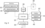
- the VR system 20 has a controller 32, a memory 34, RAM 36 and a VR interface 38 to the VR headset 24, for transmitting and receiving the signals shown in Figure 2 .
- a database 40 may also be provided for storing such data as rulesets and/or trained learning models to be described later on.
- a display 42, keyboard 44 and mouse 46 may also be provided for displaying and interacting with a user interface, which is needed in situations where some manual control, interaction or video processing is involved, as will be described.
- the controller 32 is connected to each of the other components in order to control operation thereof.
- the memory 34 may be a non-volatile memory such as read only memory (ROM) a hard disk drive (HDD) or a solid state drive (SSD).
- the memory 34 stores, amongst other things, an operating system 48 and one or more software applications 50.
- the RAM 36 is used by the controller 32 for the temporary storage of data.
- the operating system 48 may contain code which, when executed by the controller 32 in conjunction with RAM 36, controls operation of each of the hardware components of the terminal.
- the controller 32 may take any suitable form. For instance, it may be a microcontroller, plural microcontrollers, a processor, or plural processors.
- the user's current view is limited to a sector 26 which is significantly less than the full 360 degree field-of-view of the space.
- the software application 50 is therefore arranged to notify the user of events which occur outside of the viewed sector 26 by means of display within a selected sub-portion of said sector 26.
- the sub-portion is an area which is smaller than that of the currently-viewed sector.
- a notification may in some embodiments be a textual or graphical indication of the event.
- an arrow may be displayed which indicates where the event is.
- an icon or emoticon may be displayed which gives an indication of the event or of its relative importance.
- a new event or fast-moving event may be indicated by a larger icon than an existing or slow-moving event, or a flashing icon may be used for more important events.
- a textual summary of the event itself may be displayed, such as "person moving behind you". Any combination of text and graphic notifications can be employed.
- the notification provided is captured video of the detected event, which is overlaid within the selected sub-portion of the current viewed sector 26.
- a sector detection module 51 is configured to detect the current viewed sector 26 and to determine therefrom the non-viewed spatial field, which can be divided into multiple sectors to partition subsequent image processing stages.
- the different non-viewed sectors may or may not overlap.
- the non-viewed spatial field outside of area 26 can be divided into two, three or more sectors.
- a gaze detection module 52 is configured to detect the current gaze direction or focal area of the user using eye-tracking sensors in the VR headset 24; in other words, the module 52 determines which areas within the current sector 26 the user is particularly interested in. In some embodiments, the gaze detection module 52 is not required and user orientation is used to estimate a focal area.
- a free area detection module 53 is configured to identify one or more sub-portions of the current viewed sector 26 in which to overlay the event notification. Identification of the or each free sub-portion can use various methods.
- the free area detection module 53 uses the gaze direction data from the gaze detection module 52 and creates a binary mask on the area or areas which the user is focussing on.
- the non-masked area or areas is/are the sub-portion(s) that is or are available for overlaying the event notification. Otherwise, overlaying of a notification will disrupt the user experience.
- the free area detection module 53 may use a rule-based method, applying one or more rules stored in the database 40.
- the rules may, for example, perform visual analysis of the current viewed sector to identify static regions and/or those of relatively uniform colour or intensity.
- a static region may be the selected sub-portion. Note that gaze direction is not needed in this case.
- the free area detection module 53 may use a machine learning approach, employing a machine learning model trained offline to detect particular objects or areas such as walls and furniture. Neural networks may be used for this purpose. For example, a wall may be the selected sub-portion. Note that gaze direction is not needed in this case.
- the free area detection module 53 may use a score or rank -based approach, whereby, for example, all available areas within the viewed sector but outside of the user's gaze are divided and scored based on some suitability rule with the selected sub-portion being that which maximises the score. For example, where a plurality of static sub-portions are identified outside of the user's gaze direction, each static sub-portion is scored based on factors such as size, distance from the user's gaze etc. and the most optimal sub-portion selected.
- the selected sub-portion may be determined based on size. That is, if it is assumed that the event to be notified from the non-viewed part of the virtual space 30 should not be resized, or be above a minimum size, then the free area should be selected accordingly. Shrinking or distortion of the event should be minimised, preferably.
- the free area detection module 53 may receive manual selection of the sub-portion through a user interface, applicable where the VR content is a non-live feed.
- the suitable areas from the viewed field 26 can be manually masked during production, or virtually masked during post-production, for example by placing landmarks in such areas.
- tags provided with positioning sensors such as HAIP tags can represent the landmarks and marked on the user interface.
- An event detection module 54 is configured through visual analysis of video data from the non-viewed spatial field to identify one or more events for notification to the user, e.g. for overlaying within the sub-portion mentioned above. This may be performed in real time during content consumption, for example to take into account a user's interests, or can be done offline in post-production. In the offline analysis case, the event detection module 54 may analyse all sectors. Then, at consumption phase, the system may take into account only the events which were detected in sectors which are not currently viewed by the considered user.
- the event detection module 54 continuously attempts to detect events in the non-viewed sector or sectors.
- An event may comprise any detected change in video content in sequential video frames.
- an event may comprise one or more of:
- a rule or pre-trained learned model approach can be used to avoid or minimise notifying trivial events.
- a rule-based approach might for example identify that any movement or other change of appearance is an event of interest, or alternatively movement over a particular spatial threshold.
- a pre-trained deep learning model might be applied, for example using a convolutional neural network which extracts visual features in association with a recurrent neural network for handling the temporal aspects of the video.
- a Long-Short Term Memory Network is one example of a recurrent neural network.
- Such a model can be pre-trained on appropriate video datasets of common events, such as in Hollywood2, UCF101 etc.
- the event detection visual analysis may be applied individually to multiple sectors of the non-viewed field.
- the event detection visual analysis may be performed for each one of multiple spatial sub-areas or 'crops' within a given sector.
- a crop is a sub-sector of the non-viewed spatial field. If an event is detected within multiple crops, the crop with the minimal, usually smallest, spatial extent may be retained as the final event detection.
- An event overlay module 55 is configured to display the event notification in the selected free sub-portion which is being viewed.
- the event overlay module 55 may transform the video in dependence on attributes of the sub-portion. This may involve performing spatial or geometric transformations to the event video; this may involve converting a three dimensional or spherical view to a planar surface. The exact distortion and/or orientation transformation may depend on the geometry of the target sub-portion surface.
- the event detection module 54 is configured to minimise the required spatial extent of the event video by attempting to re-detect the same event in multiple crop areas of different size. Once a minimum crop size is identified for the available sub-portion, this will represent the event content.
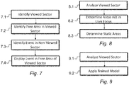
- Figure 7 shows processing steps performed by the software application 50 in one embodiment.
- a first step 7.1 the viewed sector is identified and, by inference, one or more non-viewed sectors identified.
- a free sub-portion area is identified in the viewed sector.
- an event is identified in the one or more non-viewed sectors.
- step 7.4 the event is displayed in the sub-portion identified in step 7.2. Steps 7.2 and 7.3 can be interchanged.
- Figure 8 shows sub-steps performed as part of step 7.2 in one example embodiment.
- step 8.1 visual analysis is performed in the viewed sector.
- step 8.2 one or more areas of the viewed sector which are not part of the user's focus are determined, i.e. non-masked areas.
- step 8.3 a static area of the non-masked areas is identified as the free sub-portion area.
- Figure 9 shows sub-steps performed as part of step 7.2 in another example embodiment.
- step 9.1 visual analysis is performed on the viewed sector.
- step 9.2 a trained model is applied to identify the free sub-portion area.
- Figure 10 shows sub-steps performed as part of step 7.3 in one example embodiment.
- step 10.1 visual analysis is performed on video content in the non-viewed sector or sectors.
- step 10.2 an event is manually selected, or automatically identified through a rule-based approach, from the video content.
- step 10.3 said event is displayed in the free sub-portion area determined in step 7.2.
- Figure 11 shows sub-steps performed as part of step 7.3 in another example embodiment.
- step 11.1 visual analysis is performed on video content in the non-viewed sector or sectors.
- step 11.2 a trained model is applied to the video content.
- step 11.3 an event is automatically identified and in step 11.4 is displayed in the free sub-portion area determined in step 11.4.
- Figure 12 shows sub-steps performed as part of step 7.3 in another example embodiment.
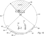
- visual analysis of each non-viewed sector is performed for multiple crop areas, indicated visually in Figure 13 .
- step 12.1 video content is received corresponding to the non-viewed sectors 61, 62, 63.
- step 12.2 each said sector 61, 62, 63 is divided into multiple crop areas, being two-dimensional spatial sub-areas. Taking only the sector 62 as an example, video analysis is performed on each of five crop areas 64 - 68.
- step 12.3 a trained model is applied to each of the crop areas 64 - 68 to identify an event of interest.
- step 12.4 the event of interest is identified. In this case, it determined that the person 15' moving relative to the background is the event of interest.
- step 12.5 it is determined if said event of interest is present in multiple ones of the crop areas 64 - 68.
- a second crop area may consist of a portion of a first crop area.
- the event detection module may first detect an event within the first crop area.
- the event detection module 54 may attempt to re-detect the same event within the second crop area. In case of a successful re-detection, the event detection module 54 may select the sub-area corresponding to the second crop, thereby minimizing the required spatial extent of the event video.
- Figure 14 shows the video data presented to the user through the VR headset 24 resulting from the Figure 12 method.
- the free sub-portion area is the background wall behind the television 11'.
- the video data from crop 66 is overlaid onto this free area to display a composite virtual space in which an event behind the user is notified through static or moving video, and without the user having to turn their head.
Landscapes
- Engineering & Computer Science (AREA)
- Theoretical Computer Science (AREA)
- Physics & Mathematics (AREA)
- General Physics & Mathematics (AREA)
- General Engineering & Computer Science (AREA)
- Human Computer Interaction (AREA)
- Multimedia (AREA)
- User Interface Of Digital Computer (AREA)
Abstract
Description
- This specification relates generally to a method and system for virtual reality display, particularly virtual reality display in which events occurring out of a user's viewing area are notified in the viewing area.
- Virtual reality is an immersive form of multimedia which involves displaying a virtual world within a user device, which is typically a headset worn by the user which has two screens (one for each eye) displaying part of the virtual world dependent on the position and/or orientation of the user detected using sensors. Headphones are also usually provided in the headset providing audio and thereby augmenting the virtual experience. The virtual world may be computer generated from a real world space captured using a suitable camera system comprising multiple camera sensors oriented in respective directions, typically capturing a 360 degree view field. Nokia's OZO (RTM) camera is one such device, providing both spatial video and audio signals for processing and rendering using suitable virtual reality software on a computer system. Sensor signals received from the headset are used by the computer system to determine the spatial location and eye orientation of the user within the virtual space, and therefore a view sector to display to the screens. The view sector will be a limited angle, less than the full view field and leaves one or more non-viewed sectors within which events may occur. The virtual world may be delivered by a live feed from the camera in a real world space, or may be stored in advance.
- Events occurring within a non-viewed sector of the virtual world may be of interest to the user. However, the user is required to turn their head away from the viewed sector to view this event, which may actually be less interesting or important than the event they were originally viewing.
- According to one aspect, a method comprises: providing video data representing at least part of virtual space to a user for viewing; identifying a current viewed sector of the virtual space based on user position; determining a sub-portion of said viewing sector; identifying an event occurring in a non-viewed sector of the virtual space; and displaying content indicative of the event in the sub-portion of said current viewing sector.
- The displaying step may comprise displaying a graphical notification of the event in the sub-portion.
- The displaying step may comprise displaying video data showing the event in the sub-portion.
- The step of determining the sub-portion may comprise receiving manual selection through a user interface.
- The step of determining the sub-portion may be performed automatically using image or video attributes within the viewed sector.
- The step of determining the sub-portion may use predefined rules to identify substantially static and/or uniform graphical areas within the viewed sector.
- Multiple possible sub-portions may be identified and ranked using the predefined rules, and wherein the method further comprises selecting a sub-portion based on rank.
- The method may further comprise detecting a focal area within the current viewed sector and wherein the sub-portion is determined to be outside of the focal area.
- The step of detecting the focal area may be based on the detected gaze direction of the user.
- A trained model may be used to determine the sub-portion.
- The step of identifying the event may comprise receiving manual selection through a user interface.
- The step of identifying the event may be performed automatically using predefined rules.
- The step of identifying the event may be performed automatically using a trained model. The trained model may use a convolutional neural network and a recurrent neural network.
- The non-viewed sector may be divided into multiple sub-sectors and each is analysed individually to identify an event.
- The method may further comprise receiving video data corresponding to different spatial crop areas of the non-viewed sector(s) and wherein if the identified event occurs within multiple crop areas, the displaying step displays video data from the smallest crop area.
- The video data showing the identified event may be substantially kept the same size when displayed.
- The video data showing the identified event may be transformed in correspondence to the sub-portion.
- The video data showing the identified event may be transformed from a three-dimensional or polar representation to a two-dimensional representation.
- According to a second aspect, there may be provided a computer program comprising instructions that when executed by a computer apparatus control it to perform the method.
- According to a third aspect, there may be provided a non-transitory computer-readable storage medium having stored thereon computer-readable code, which, when executed by at least one processor, causes the at least one processor to perform a method, comprising: providing video data representing at least part of a virtual space to a user for viewing; identifying a current viewed sector of the virtual space based on user position; determining a sub-portion of said viewing sector; identifying an event occurring in a non-viewed sector of the virtual space; and displaying content indicative of the event in the sub-portion of said current viewing sector.
- According to a fourth aspect, there may be provided an apparatus, the apparatus having at least one processor and at least one memory having computer-readable code stored thereon which when executed controls the at least one processor of an audio capture apparatus: to provide video data representing at least part of a virtual space to a user for viewing; to identify a current viewed sector of the virtual space based on user position; to determine a sub-portion of said viewing sector; to identify an event occurring in a non-viewed sector of the virtual space; and to display content indicative of the event in the sub-portion of said current viewing sector. The apparatus may be further configured to perform the above embodiments of the method.
- According to a fifth aspect, there may be provided an apparatus comprising means for providing video data representing at least part of a virtual space to a user for viewing; means for identifying a current viewed sector of the virtual space based on user position; means for determining a sub-portion of said viewing sector; means for identifying an event occurring in a non-viewed sector of the virtual space; and means for displaying content indicative of the event in the sub-portion of said current viewing sector. The apparatus may further comprise means for performing the above embodiments of the method.
- Embodiments will now be described, by way of non-limiting example, with reference to the accompanying drawings, in which.
-
Figure 1 is a top-plan view of a real world capture situation for creating a virtual reality version, which is useful for understanding embodiments; -
Figure 2 is a schematic diagram illustrating components of a virtual reality system in relation to capture and playback devices; -
Figure 3 is a top-plan view of a virtual reality space created using theFigure 2 system; -
Figure 4 is a graphical representation of a viewed sector in theFigure 3 space; -
Figure 5 is a schematic diagram showing components of the virtual reality system in accordance with an embodiment; -
Figure 6 is a schematic diagram showing functional modules of a software application in accordance with an embodiment; -
Figure 7 is a flow diagram showing processing steps performed by theFigure 6 software application; -
Figure 8 is a flow diagram showing processing sub-steps performed as part of the second step inFigure 7 ; -
Figure 9 is a flow diagram showing alternative processing sub-steps performed as part of the second step inFigure 7 ; -
Figure 10 is a flow diagram showing processing sub-steps performed as part of the third step inFigure 7 ; -
Figure 11 is a flow diagram showing alternative processing sub-steps performed as part of the third step inFigure 7 ; -
Figure 12 is a flow diagram showing alternative processing sub-steps performed as part of the third step inFigure 7 ; -
Figure 13 is a top-plan view of theFigure 2 virtual reality space which is modified to explain the processing steps inFigure 12 ; and -
Figure 14 is a modified version of theFigure 4 graphical representation in which the viewed sector is augmented by performing one or more embodiments. - Embodiments herein relate to virtual reality (VR) methods and systems, in which a user is provided with a live or stored video feed representing a virtual space. Spatial audio may also be provided.
- In this context, a virtual space is any computer generated version of a space, for example a captured real world space, in which a user can be immersed through a visual interface device such as a VR headset.
- In some embodiments, a live feed may be provided by a VR system that receives a current version of a real world space from one or more cameras in said space, such as the abovementioned OZO camera which incorporates multiple video sensors. In some embodiments, the virtual space is stored on memory of the VR system and possibly pre or post -processed by user interaction through a user interface of the system prior to delivery to the user.
- What is presented by the VR system to the user is determined by data signals received from a VR headset worn by the user indicative of one or more of its spatial position and orientation. For ease of reference, we refer to these signals as position signals or position data. The VR headset incorporates motion tracking sensors which may include gyroscopes, accelerometers and structured light systems. These sensors generate the position data from which the current viewing field, or sector, is determined and updated as the user changes position. The VR headset will typically comprise two digital screens for displaying stereoscopic video images of the virtual world in front of respective eyes of the user, and also two speakers for delivering audio, if provided from the VR system. The embodiments herein, which primarily relate to the delivery of VR content, are not limited to a particular type of VR headset.
- Referring to
Figure 1 , an example of capturing VR video content is shown in relation to areal world space 1 shown in top plan view. Within thespace 1 is acamera system 3, which may be multiple cameras or Nokia's OZO system, which captures in real-time video with a horizontal, 360 degree field-of-view, indicated generally byarrows 5. In the vertical plane, a 360 degree field-of-view may be captured to create a complete spherical world, or alternatively, a more limited angle may be used. Within this field-of-view are various objects, including asofa 7 on which is seated afirst person 9. In front of thesofa 7 is atelevision 11. Spatially behind thesofa 7 is asecond sofa 13 and asecond person 15 who may or may not be moving. - Referring to
Figure 2 , a VR processing and rendering system 20 (hereafter referred to simply as the VR system) is shown in relation to thecamera 3 for generating avirtual space 22 displayed in computer-generated form within aVR headset 24. TheVR system 20 receives from thecamera 3 video and audio data and generates thevirtual space 22 in data form ready for display to theVR headset 24. - In use, the
VR system 20 receives from theVR headset 24 position data, and responsive thereto delivers to the headset video and audio data corresponding to a limited spatial sector of the virtual space which the user is currently looking at. - A sector refers to any sub-portion of the available spatial field, in this case less than 360 degrees and more likely to be in the order of 70 - 100 degrees. As the user changes position, a different sector of the available spatial field is delivered in real time or near real time. The different sector may overlap with a previous sector.
- Reference to position and position data refers to any parameter indicative of user positioning and/or orientation within the virtual space which can be used to determine what sector the user views at a particular point in time. Position can include the spatial position within the virtual space, for example in terms of Cartesian or polar co-ordinates or distance from a reference position. Position can also be indicative of orientation of the headset in terms of horizontal and/or vertical direction relative to a reference direction, e.g. 10 degrees from a reference direction.
- For example, a gyroscope is an example of a motion tracking sensor within a VR headset which can detect orientation based on a measured change in direction from a reference position.
- In general, the position can be deduced based on signals received from motion tracking sensors on the VR headset, which will typically incorporate one or more of gyroscopes, accelerometers and/or structured light systems. In other embodiments, optical, electromagnetic and/or audio tracking sensors can also be used. In other embodiments, position can be determined by sensors external to the VR headset, for example one or more cameras directed at a user carrying markers.
- Additionally, or alternatively, the spatial position can be determined by the user carrying a positioning tag (not shown) which may directly or indirectly deliver data indicative of the user position to the
VR system 20. The positioning tag may be a High Accuracy Indoor Positioning (HAIP) tag which works in association with one or more HAIP locators. - In addition to the position, the
processing system 20 can also take into account data indicating the current gaze direction or focus area of the user, which can be received from theVR headset 24 using eye tracking technology. Eye tracking technology may employ cameras mounted on the inside of the VR headset which are directed towards the user's eyes and measure changes in direction from a reference position, which is usually set when the eyes are looking directly ahead. - Referring now to
Figure 3 , avirtual space 30 corresponding to that captured by theVR system 20 is shown, again in top plan view. The user withVR headset 24 is shown within saidvirtual space 30 with a limited field of view indicated by theshaded sector 26. Responsive to this orientation, theVR headset 24 will display to the user a computer-generated version of the sofa 7', first person 9' and the television 11' for which see alsoFigure 4 which gives the user's view. - For completeness, and referring now to
Figure 5 , an example schematic diagram of components of theVR system 20 is shown. TheVR system 20 has acontroller 32, amemory 34,RAM 36 and a VR interface 38 to theVR headset 24, for transmitting and receiving the signals shown inFigure 2 . Adatabase 40 may also be provided for storing such data as rulesets and/or trained learning models to be described later on. Adisplay 42,keyboard 44 andmouse 46 may also be provided for displaying and interacting with a user interface, which is needed in situations where some manual control, interaction or video processing is involved, as will be described. Thecontroller 32 is connected to each of the other components in order to control operation thereof. - The
memory 34 may be a non-volatile memory such as read only memory (ROM) a hard disk drive (HDD) or a solid state drive (SSD). Thememory 34 stores, amongst other things, anoperating system 48 and one ormore software applications 50. TheRAM 36 is used by thecontroller 32 for the temporary storage of data. Theoperating system 48 may contain code which, when executed by thecontroller 32 in conjunction withRAM 36, controls operation of each of the hardware components of the terminal. - The
controller 32 may take any suitable form. For instance, it may be a microcontroller, plural microcontrollers, a processor, or plural processors. - As will be seen from
Figures 3 and4 , the user's current view is limited to asector 26 which is significantly less than the full 360 degree field-of-view of the space. Thesoftware application 50 is therefore arranged to notify the user of events which occur outside of the viewedsector 26 by means of display within a selected sub-portion of saidsector 26. - The sub-portion is an area which is smaller than that of the currently-viewed sector.
- In this context, a notification may in some embodiments be a textual or graphical indication of the event. For example, an arrow may be displayed which indicates where the event is. In another example, an icon or emoticon may be displayed which gives an indication of the event or of its relative importance. A new event or fast-moving event may be indicated by a larger icon than an existing or slow-moving event, or a flashing icon may be used for more important events. In another example, a textual summary of the event itself may be displayed, such as "person moving behind you". Any combination of text and graphic notifications can be employed.
- In embodiments to be described below, the notification provided is captured video of the detected event, which is overlaid within the selected sub-portion of the current viewed
sector 26. - Referring to
Figure 6 , functional modules of thesoftware application 50 are shown. - A
sector detection module 51 is configured to detect the current viewedsector 26 and to determine therefrom the non-viewed spatial field, which can be divided into multiple sectors to partition subsequent image processing stages. The different non-viewed sectors may or may not overlap. For example, with reference toFigure 3 , the non-viewed spatial field outside ofarea 26 can be divided into two, three or more sectors. - A
gaze detection module 52 is configured to detect the current gaze direction or focal area of the user using eye-tracking sensors in theVR headset 24; in other words, themodule 52 determines which areas within thecurrent sector 26 the user is particularly interested in. In some embodiments, thegaze detection module 52 is not required and user orientation is used to estimate a focal area. - A free
area detection module 53 is configured to identify one or more sub-portions of the current viewedsector 26 in which to overlay the event notification. Identification of the or each free sub-portion can use various methods. - In some embodiments, the free
area detection module 53 uses the gaze direction data from thegaze detection module 52 and creates a binary mask on the area or areas which the user is focussing on. In this case, the non-masked area or areas is/are the sub-portion(s) that is or are available for overlaying the event notification. Otherwise, overlaying of a notification will disrupt the user experience. - In some embodiments, the free
area detection module 53 may use a rule-based method, applying one or more rules stored in thedatabase 40. The rules may, for example, perform visual analysis of the current viewed sector to identify static regions and/or those of relatively uniform colour or intensity. A static region may be the selected sub-portion. Note that gaze direction is not needed in this case. - In some embodiments, the free
area detection module 53 may use a machine learning approach, employing a machine learning model trained offline to detect particular objects or areas such as walls and furniture. Neural networks may be used for this purpose. For example, a wall may be the selected sub-portion. Note that gaze direction is not needed in this case. - In some embodiments, the free
area detection module 53 may use a score or rank -based approach, whereby, for example, all available areas within the viewed sector but outside of the user's gaze are divided and scored based on some suitability rule with the selected sub-portion being that which maximises the score. For example, where a plurality of static sub-portions are identified outside of the user's gaze direction, each static sub-portion is scored based on factors such as size, distance from the user's gaze etc. and the most optimal sub-portion selected. - In some embodiments, the selected sub-portion may be determined based on size. That is, if it is assumed that the event to be notified from the non-viewed part of the
virtual space 30 should not be resized, or be above a minimum size, then the free area should be selected accordingly. Shrinking or distortion of the event should be minimised, preferably. - In some embodiments, the free
area detection module 53 may receive manual selection of the sub-portion through a user interface, applicable where the VR content is a non-live feed. The suitable areas from the viewedfield 26 can be manually masked during production, or virtually masked during post-production, for example by placing landmarks in such areas. In the case of physical landmarks, tags provided with positioning sensors such as HAIP tags can represent the landmarks and marked on the user interface. - An
event detection module 54 is configured through visual analysis of video data from the non-viewed spatial field to identify one or more events for notification to the user, e.g. for overlaying within the sub-portion mentioned above. This may be performed in real time during content consumption, for example to take into account a user's interests, or can be done offline in post-production. In the offline analysis case, theevent detection module 54 may analyse all sectors. Then, at consumption phase, the system may take into account only the events which were detected in sectors which are not currently viewed by the considered user. - Instead, in the real-time analysis case, the
event detection module 54 continuously attempts to detect events in the non-viewed sector or sectors. - An event may comprise any detected change in video content in sequential video frames. For example, an event may comprise one or more of:
- an object entering the virtual space;
- an object moving or changing its position in the virtual space;
- an object changing its movement in the virtual space;
- an object changing its appearance, for example in terms of colour or size;
- multiple objects interacting with each other, such as a soccer player interacting with a ball and/or with other players.
- In some embodiments, a rule or pre-trained learned model approach can be used to avoid or minimise notifying trivial events. A rule-based approach might for example identify that any movement or other change of appearance is an event of interest, or alternatively movement over a particular spatial threshold. In a learned model approach, a pre-trained deep learning model might be applied, for example using a convolutional neural network which extracts visual features in association with a recurrent neural network for handling the temporal aspects of the video. A Long-Short Term Memory Network is one example of a recurrent neural network. Such a model can be pre-trained on appropriate video datasets of common events, such as in Hollywood2, UCF101 etc.
- The event detection visual analysis may be applied individually to multiple sectors of the non-viewed field.
- The event detection visual analysis may be performed for each one of multiple spatial sub-areas or 'crops' within a given sector. In this context, a crop is a sub-sector of the non-viewed spatial field. If an event is detected within multiple crops, the crop with the minimal, usually smallest, spatial extent may be retained as the final event detection.
- An
event overlay module 55 is configured to display the event notification in the selected free sub-portion which is being viewed. In some embodiments, particularly where video of the event is overlaid on the sub-portion, theevent overlay module 55 may transform the video in dependence on attributes of the sub-portion. This may involve performing spatial or geometric transformations to the event video; this may involve converting a three dimensional or spherical view to a planar surface. The exact distortion and/or orientation transformation may depend on the geometry of the target sub-portion surface. In some embodiments, theevent detection module 54 is configured to minimise the required spatial extent of the event video by attempting to re-detect the same event in multiple crop areas of different size. Once a minimum crop size is identified for the available sub-portion, this will represent the event content. -
Figure 7 shows processing steps performed by thesoftware application 50 in one embodiment. In a first step 7.1 the viewed sector is identified and, by inference, one or more non-viewed sectors identified. In the next step 7.2, a free sub-portion area is identified in the viewed sector. In step 7.3, an event is identified in the one or more non-viewed sectors. In step 7.4 the event is displayed in the sub-portion identified in step 7.2. Steps 7.2 and 7.3 can be interchanged. -
Figure 8 shows sub-steps performed as part of step 7.2 in one example embodiment. In step 8.1 visual analysis is performed in the viewed sector. In step 8.2 one or more areas of the viewed sector which are not part of the user's focus are determined, i.e. non-masked areas. In step 8.3, a static area of the non-masked areas is identified as the free sub-portion area. -
Figure 9 shows sub-steps performed as part of step 7.2 in another example embodiment. In step 9.1 visual analysis is performed on the viewed sector. In step 9.2 a trained model is applied to identify the free sub-portion area. -
Figure 10 shows sub-steps performed as part of step 7.3 in one example embodiment. In step 10.1 visual analysis is performed on video content in the non-viewed sector or sectors. In step 10.2 an event is manually selected, or automatically identified through a rule-based approach, from the video content. In step 10.3 said event is displayed in the free sub-portion area determined in step 7.2. -
Figure 11 shows sub-steps performed as part of step 7.3 in another example embodiment. In step 11.1 visual analysis is performed on video content in the non-viewed sector or sectors. In step 11.2, a trained model is applied to the video content. In step 11.3 an event is automatically identified and in step 11.4 is displayed in the free sub-portion area determined in step 11.4. -
Figure 12 shows sub-steps performed as part of step 7.3 in another example embodiment. In this embodiment, visual analysis of each non-viewed sector is performed for multiple crop areas, indicated visually inFigure 13 . - In step 12.1, video content is received corresponding to the
non-viewed sectors sector sector 62 as an example, video analysis is performed on each of five crop areas 64 - 68. In step 12.3, a trained model is applied to each of the crop areas 64 - 68 to identify an event of interest. In step 12.4 the event of interest is identified. In this case, it determined that the person 15' moving relative to the background is the event of interest. In step 12.5 it is determined if said event of interest is present in multiple ones of the crop areas 64 - 68. If not, then the crop area which shows the event is displayed in the free area in step 12.7. If present in multiple crops, then in step 12.6 it is determined which of the crop areas has the smallest extent. In this case, the moving person 15' appears in both the second andthird crops third crop 66 is displayed in the free sub-portion space within the viewedsector 26. According to an embodiment, a second crop area may consist of a portion of a first crop area. The event detection module may first detect an event within the first crop area. Theevent detection module 54 may attempt to re-detect the same event within the second crop area. In case of a successful re-detection, theevent detection module 54 may select the sub-area corresponding to the second crop, thereby minimizing the required spatial extent of the event video. -
Figure 14 shows the video data presented to the user through theVR headset 24 resulting from theFigure 12 method. In this case, the free sub-portion area is the background wall behind the television 11'. The video data fromcrop 66 is overlaid onto this free area to display a composite virtual space in which an event behind the user is notified through static or moving video, and without the user having to turn their head. - It will be appreciated that the above described embodiments are purely illustrative and are not limiting on the scope of protection. Other variations and modifications will be apparent to persons skilled in the art upon reading the present application.
- Moreover, the disclosure of the present application should be understood to include any novel features or any novel combination of features either explicitly or implicitly disclosed herein or any generalization thereof and during the prosecution of the present application or of any application derived therefrom, new claims may be formulated to cover any such features and/or combination of such features.
Claims (15)
- A method comprising:providing video data representing at least part of virtual space to a user for viewing;identifying a current viewed sector of the virtual space based on user position;determining a sub-portion of said viewing sector;identifying an event occurring in a non-viewed sector of the virtual space; anddisplaying content indicative of the event in the sub-portion of said current viewing sector, wherein the displaying step comprises displaying video data showing the event in the sub-portion.
- The method of claim 1, wherein the step of determining the sub-portion comprises receiving manual selection through a user interface.
- The method of claim 1 or 2, wherein the step of determining the sub-portion is performed automatically using image or video attributes within the viewed sector.
- The method of claim 3, wherein the step of determining the sub-portion uses predefined rules to identify substantially static and/or uniform graphical areas within the viewed sector.
- The method of claim 4, wherein multiple possible sub-portions are identified and ranked using the predefined rules, and wherein the method further comprises selecting a sub-portion based on rank.
- The method of any of any preceding claim, further comprising detecting a focal area within the current viewed sector and wherein the sub-portion is determined to be outside of the focal area.
- The method of claim 6, wherein the step of detecting the focal area is based on the detected gaze direction of the user.
- The method of any preceding claim, wherein the step of identifying the event comprises receiving manual selection through a user interface.
- The method of any preceding claim, wherein the non-viewed sector is divided into multiple sub-sectors and each is analysed individually to identify an event.
- The method of any preceding claim, wherein the method further comprises receiving video data corresponding to different spatial crop areas of the non-viewed sector(s) and wherein if the identified event occurs within multiple crop areas, the displaying step displays video data from the smallest crop area.
- The method of any preceding claim, wherein the video data showing the identified event is substantially kept the same size when displayed.
- The method of any preceding claim, wherein the video data showing the identified event is transformed in correspondence to the sub-portion.
- The method of claim 12, wherein the video data showing the identified event is transformed from a three-dimensional or polar representation to a two-dimensional representation.
- A computer program configured to:provide video data representing at least part of a virtual space to a user for viewing;identify a current viewed sector of the virtual space based on user position;determine a sub-portion of said viewing sector;identify an event occurring in a non-viewed sector of the virtual space; anddisplay content indicative of the event in the sub-portion of said current viewing sector, wherein the displayed content comprises video data showing the event in the sub-portion.
- Apparatus configured to:provide video data representing at least part of a virtual space to a user for viewing;identify a current viewed sector of the virtual space based on user position;determine a sub-portion of said viewing sector;identify an event occurring in a non-viewed sector of the virtual space; anddisplay content indicative of the event in the sub-portion of said current viewing sector, wherein the displayed content comprises displaying video data showing the event in the sub-portion.
Applications Claiming Priority (1)
| Application Number | Priority Date | Filing Date | Title |
|---|---|---|---|
| GBGB1608886.6A GB201608886D0 (en) | 2016-05-20 | 2016-05-20 | Virtual reality display |
Publications (1)
| Publication Number | Publication Date |
|---|---|
| EP3246793A1 true EP3246793A1 (en) | 2017-11-22 |
Family
ID=56369680
Family Applications (1)
| Application Number | Title | Priority Date | Filing Date |
|---|---|---|---|
| EP17171688.9A Withdrawn EP3246793A1 (en) | 2016-05-20 | 2017-05-18 | Virtual reality display |
Country Status (3)
| Country | Link |
|---|---|
| US (1) | US10482641B2 (en) |
| EP (1) | EP3246793A1 (en) |
| GB (1) | GB201608886D0 (en) |
Cited By (1)
| Publication number | Priority date | Publication date | Assignee | Title |
|---|---|---|---|---|
| EP3506054A1 (en) * | 2017-12-27 | 2019-07-03 | Nokia Technologies Oy | Enabling rendering, for consumption by a user, of mediated reality content |
Citations (2)
| Publication number | Priority date | Publication date | Assignee | Title |
|---|---|---|---|---|
| US20140375683A1 (en) * | 2013-06-25 | 2014-12-25 | Thomas George Salter | Indicating out-of-view augmented reality images |
| US20150243079A1 (en) * | 2014-02-27 | 2015-08-27 | Lg Electronics Inc. | Head mounted display providing closed-view and method of controlling therefor |
Family Cites Families (13)
| Publication number | Priority date | Publication date | Assignee | Title |
|---|---|---|---|---|
| US7737965B2 (en) | 2005-06-09 | 2010-06-15 | Honeywell International Inc. | Handheld synthetic vision device |
| US8217518B2 (en) * | 2006-03-08 | 2012-07-10 | Stmicroelectronics Asia Pacific Pte., Ltd. | Enhancing metal/low-K interconnect reliability using a protection layer |
| US8493408B2 (en) * | 2008-11-19 | 2013-07-23 | Apple Inc. | Techniques for manipulating panoramas |
| US20100182340A1 (en) * | 2009-01-19 | 2010-07-22 | Bachelder Edward N | Systems and methods for combining virtual and real-time physical environments |
| EP2473871B1 (en) * | 2009-09-01 | 2015-03-11 | Magna Mirrors Of America, Inc. | Imaging and display system for vehicle |
| US8933961B2 (en) * | 2009-12-10 | 2015-01-13 | Harris Corporation | Video processing system generating corrected geospatial metadata for a plurality of georeferenced video feeds and related methods |
| JP5691568B2 (en) | 2011-01-28 | 2015-04-01 | ソニー株式会社 | Information processing apparatus, notification method, and program |
| JP5747673B2 (en) * | 2011-06-10 | 2015-07-15 | ソニー株式会社 | Information processing apparatus, information processing method, and program |
| US9081177B2 (en) | 2011-10-07 | 2015-07-14 | Google Inc. | Wearable computer with nearby object response |
| KR101449160B1 (en) * | 2012-12-12 | 2014-10-08 | 현대자동차주식회사 | Apparatus and method for providing information of blind spot |
| US20160307374A1 (en) | 2013-12-19 | 2016-10-20 | Metaio Gmbh | Method and system for providing information associated with a view of a real environment superimposed with a virtual object |
| US20160150212A1 (en) * | 2014-11-26 | 2016-05-26 | Sony Corporation | Live selective adaptive bandwidth |
| US9569696B1 (en) * | 2015-08-12 | 2017-02-14 | Yahoo! Inc. | Media content analysis system and method |
-
2016
- 2016-05-20 GB GBGB1608886.6A patent/GB201608886D0/en not_active Ceased
-
2017
- 2017-05-10 US US15/591,540 patent/US10482641B2/en active Active
- 2017-05-18 EP EP17171688.9A patent/EP3246793A1/en not_active Withdrawn
Patent Citations (2)
| Publication number | Priority date | Publication date | Assignee | Title |
|---|---|---|---|---|
| US20140375683A1 (en) * | 2013-06-25 | 2014-12-25 | Thomas George Salter | Indicating out-of-view augmented reality images |
| US20150243079A1 (en) * | 2014-02-27 | 2015-08-27 | Lg Electronics Inc. | Head mounted display providing closed-view and method of controlling therefor |
Non-Patent Citations (1)
| Title |
|---|
| TORBEN SCHINKE ET AL: "Visualization of off-screen objects in mobile augmented reality", PROCEEDINGS OF THE 12TH INTERNATIONAL CONFERENCE ON HUMAN COMPUTER INTERACTION WITH MOBILE DEVICES AND SERVICES; LISBON, PORTUGAL ; SEPTEMBER 07 - 10, 2010, ACM, NEW YORK, NY, 7 September 2010 (2010-09-07), pages 313 - 316, XP058182474, ISBN: 978-1-60558-835-3, DOI: 10.1145/1851600.1851655 * |
Cited By (1)
| Publication number | Priority date | Publication date | Assignee | Title |
|---|---|---|---|---|
| EP3506054A1 (en) * | 2017-12-27 | 2019-07-03 | Nokia Technologies Oy | Enabling rendering, for consumption by a user, of mediated reality content |
Also Published As
| Publication number | Publication date |
|---|---|
| US20170337720A1 (en) | 2017-11-23 |
| US10482641B2 (en) | 2019-11-19 |
| GB201608886D0 (en) | 2016-07-06 |
Similar Documents
| Publication | Publication Date | Title |
|---|---|---|
| US11238666B2 (en) | Display of an occluded object in a hybrid-reality system | |
| US10579142B2 (en) | Gaze detection method and apparatus | |
| US9778740B2 (en) | Method and system for tracking an interest of a user within a panoramic visual content | |
| US10001844B2 (en) | Information processing apparatus information processing method and storage medium | |
| US6924832B1 (en) | Method, apparatus & computer program product for tracking objects in a warped video image | |
| KR101227237B1 (en) | Augmented reality system and method for realizing interaction between virtual object using the plural marker | |
| JP5001930B2 (en) | Motion recognition apparatus and method | |
| US12444147B2 (en) | Method for determining correct scanning distance using augmented reality and machine learning models | |
| CN116820251B (en) | Gesture track interaction method, intelligent glasses and storage medium | |
| Lee et al. | Multi-modal user interaction method based on gaze tracking and gesture recognition | |
| CN115348438B (en) | Control method and related device for three-dimensional display equipment | |
| US10482641B2 (en) | Virtual reality display | |
| Chew et al. | Panorama stitching using overlap area weighted image plane projection and dynamic programming for visual localization | |
| US12530785B2 (en) | Tracking device, tracking method, and recording medium | |
| EP4086734A1 (en) | A tracking method for image generation, a computer program product and a computer system | |
| CN112580409A (en) | Target object selection method and related product | |
| KR102305880B1 (en) | User's Gaze Tracking Method, and Medium Being Recorded with Program for Executing the Method | |
| JP2022054247A (en) | Information processing device and information processing method | |
| Li et al. | A low-cost head and eye tracking system for realistic eye movements in virtual avatars | |
| JP6358996B2 (en) | Security simulation device | |
| WO2026000189A1 (en) | Safety boundary adjustment method, display device, display system and computer storage medium | |
| WO2026020404A1 (en) | Apparatus, display apparatus, method of defining boundary, and computer-program product | |
| Sarvadevabhatla et al. | Panoramic attention for humanoid robots |
Legal Events
| Date | Code | Title | Description |
|---|---|---|---|
| PUAI | Public reference made under article 153(3) epc to a published international application that has entered the european phase |
Free format text: ORIGINAL CODE: 0009012 |
|
| STAA | Information on the status of an ep patent application or granted ep patent |
Free format text: STATUS: THE APPLICATION HAS BEEN PUBLISHED |
|
| AK | Designated contracting states |
Kind code of ref document: A1 Designated state(s): AL AT BE BG CH CY CZ DE DK EE ES FI FR GB GR HR HU IE IS IT LI LT LU LV MC MK MT NL NO PL PT RO RS SE SI SK SM TR |
|
| AX | Request for extension of the european patent |
Extension state: BA ME |
|
| STAA | Information on the status of an ep patent application or granted ep patent |
Free format text: STATUS: REQUEST FOR EXAMINATION WAS MADE |
|
| 17P | Request for examination filed |
Effective date: 20180517 |
|
| RBV | Designated contracting states (corrected) |
Designated state(s): AL AT BE BG CH CY CZ DE DK EE ES FI FR GB GR HR HU IE IS IT LI LT LU LV MC MK MT NL NO PL PT RO RS SE SI SK SM TR |
|
| STAA | Information on the status of an ep patent application or granted ep patent |
Free format text: STATUS: EXAMINATION IS IN PROGRESS |
|
| 17Q | First examination report despatched |
Effective date: 20190307 |
|
| RAP1 | Party data changed (applicant data changed or rights of an application transferred) |
Owner name: NOKIA TECHNOLOGIES OY |
|
| STAA | Information on the status of an ep patent application or granted ep patent |
Free format text: STATUS: THE APPLICATION HAS BEEN WITHDRAWN |
|
| 18W | Application withdrawn |
Effective date: 20201117 |