EP3246773B1 - Verfahren zur parametrierung einer verfahrens- oder prozesstechnischen anlage - Google Patents
Verfahren zur parametrierung einer verfahrens- oder prozesstechnischen anlage Download PDFInfo
- Publication number
- EP3246773B1 EP3246773B1 EP16170003.4A EP16170003A EP3246773B1 EP 3246773 B1 EP3246773 B1 EP 3246773B1 EP 16170003 A EP16170003 A EP 16170003A EP 3246773 B1 EP3246773 B1 EP 3246773B1
- Authority
- EP
- European Patent Office
- Prior art keywords
- engineering
- parameters
- module
- user program
- function module
- Prior art date
- Legal status (The legal status is an assumption and is not a legal conclusion. Google has not performed a legal analysis and makes no representation as to the accuracy of the status listed.)
- Active
Links
Images

Classifications
-
- G—PHYSICS
- G05—CONTROLLING; REGULATING
- G05B—CONTROL OR REGULATING SYSTEMS IN GENERAL; FUNCTIONAL ELEMENTS OF SUCH SYSTEMS; MONITORING OR TESTING ARRANGEMENTS FOR SUCH SYSTEMS OR ELEMENTS
- G05B19/00—Program-control systems
- G05B19/02—Program-control systems electric
- G05B19/418—Total factory control, i.e. centrally controlling a plurality of machines, e.g. direct or distributed numerical control [DNC], flexible manufacturing systems [FMS], integrated manufacturing systems [IMS] or computer integrated manufacturing [CIM]
- G05B19/41865—Total factory control, i.e. centrally controlling a plurality of machines, e.g. direct or distributed numerical control [DNC], flexible manufacturing systems [FMS], integrated manufacturing systems [IMS] or computer integrated manufacturing [CIM] characterised by job scheduling, process planning, material flow
- G05B19/4187—Total factory control, i.e. centrally controlling a plurality of machines, e.g. direct or distributed numerical control [DNC], flexible manufacturing systems [FMS], integrated manufacturing systems [IMS] or computer integrated manufacturing [CIM] characterised by job scheduling, process planning, material flow by tool management
-
- G—PHYSICS
- G05—CONTROLLING; REGULATING
- G05B—CONTROL OR REGULATING SYSTEMS IN GENERAL; FUNCTIONAL ELEMENTS OF SUCH SYSTEMS; MONITORING OR TESTING ARRANGEMENTS FOR SUCH SYSTEMS OR ELEMENTS
- G05B19/00—Program-control systems
- G05B19/02—Program-control systems electric
- G05B19/04—Program control other than numerical control, i.e. in sequence controllers or logic controllers
- G05B19/042—Program control other than numerical control, i.e. in sequence controllers or logic controllers using digital processors
- G05B19/0426—Programming the control sequence
-
- G—PHYSICS
- G05—CONTROLLING; REGULATING
- G05B—CONTROL OR REGULATING SYSTEMS IN GENERAL; FUNCTIONAL ELEMENTS OF SUCH SYSTEMS; MONITORING OR TESTING ARRANGEMENTS FOR SUCH SYSTEMS OR ELEMENTS
- G05B19/00—Program-control systems
- G05B19/02—Program-control systems electric
- G05B19/04—Program control other than numerical control, i.e. in sequence controllers or logic controllers
- G05B19/05—Programmable logic controllers, e.g. simulating logic interconnections of signals according to ladder diagrams or function charts
- G05B19/056—Programming the PLC
-
- G—PHYSICS
- G05—CONTROLLING; REGULATING
- G05B—CONTROL OR REGULATING SYSTEMS IN GENERAL; FUNCTIONAL ELEMENTS OF SUCH SYSTEMS; MONITORING OR TESTING ARRANGEMENTS FOR SUCH SYSTEMS OR ELEMENTS
- G05B2219/00—Program-control systems
- G05B2219/20—Pc systems
- G05B2219/23—Pc programming
- G05B2219/23146—Programmable, reconfigurable via microprocessor or coding switches
-
- G—PHYSICS
- G05—CONTROLLING; REGULATING
- G05B—CONTROL OR REGULATING SYSTEMS IN GENERAL; FUNCTIONAL ELEMENTS OF SUCH SYSTEMS; MONITORING OR TESTING ARRANGEMENTS FOR SUCH SYSTEMS OR ELEMENTS
- G05B2219/00—Program-control systems
- G05B2219/30—Nc systems
- G05B2219/36—Nc in input of data, input key till input tape
- G05B2219/36186—Programming languages for lathe, mill or general use mixed
Definitions
- the invention relates to a method for parameterizing a procedural or process engineering system with at least one functional module, the functional module comprising a programmable logic controller (PLC) and a procedural or process engineering module that can be controlled and / or regulated by means of the PLC for use as a system part.
- PLC programmable logic controller
- the structure of the plant is usually recorded in a plant engineering tool in a first step and, by means of the tool, an R&I flow diagram of the plant or of Parts of the system created by linking graphic process objects.
- the graphic process objects represent the components required for the operation of the system, e.g. sensors, motors, pumps, valves, pipelines, tanks, reactors, etc., or they represent function modules that are increasingly used in the course of increasing modularization of process engineering systems .
- the trend in process engineering is moving towards modules with defined basic operations and their provision as functional units, the so-called functional modules.
- the functional modules are equipped with their own intelligence in the form of a PLC.
- the controls that can be used for this often also referred to as program logic controllers (PLC)
- PLC program logic controllers
- the user then disadvantageously has to have and be able to use engineering tools from all manufacturers of control systems that are used in the function modules of the respective system.
- the integration of the functional modules and the changing or adaptation of functions of the modules at the time of their integration into the system are therefore disadvantageously associated with a comparatively high level of effort.
- JP 2004 126817 A discloses a setup tool and an associated computer program product.
- the invention is therefore based on the object of finding a method for engineering a procedural or process-technical installation with at least one functional module, which is characterized by less effort.
- the invention has the advantage that a procedural or process engineering system with several function modules, which can be equipped with controls from different manufacturers, can be engineered without the respective manufacturer-specific engineering tools from the control manufacturer.
- the user of the system no longer has to deal with the various engineering tools of the control manufacturer when engineering his system and no longer has to acquire the specialist knowledge required to operate these tools. For the engineering of the plant, the user can now get along with a single plant engineering tool.
- the engineering of the function module which is intended for use in the system, can be carried out by the module manufacturer.
- the manufacturer of the function module for his part, can use special engineering tools that are specific to the respective manufacturer of the PLC used in the module. The module manufacturer is thus given full access to the configuration of the control when automating the function module.
- a user of the function module does not have to be given full access to the configuration of the PLC of the function module for engineering the respective system in which the module is used, and in particular for integrating the function module into the system.
- the various functional services of the module implemented by the module manufacturer can be activated and / or parameterized, so that the functional module can be individualized depending on the requirements of the user.
- the manufacturer of the function module creates a user program that can be configured using parameters for a PLC that can be freely programmed at the time the program is created. This is done by the manufacturer using a tool that is designed for engineering the respective PLC and thus for engineering the function module provided with the PLC. Using the tool, the user program created in this way is compiled and downloaded to the PLC by the module manufacturer.
- the PLC is now provided with a user program that can be configured using parameters.
- the engineering tool module which is designed to engineer the PLC, can automatically create a file when the user program is compiled, in which the parameters with which the user program can be configured are contained in a formal description language as information on the integration of the function module.
- this procedure also enables the know-how of the module manufacturer to be protected, since the user program does not have to be able to be configured by the user of the functional module but cannot be read or changed by the user.
- the user To select and define the parameters for his application-specific configuration of the function module by means of the system engineering tool, the user only needs to know which parameters and how the function module can be configured and / or parameterized for a desired function. He can get this knowledge from the file with the information on function module integration.
- the parameters can be specified, for example, by the user making entries in a plant engineering tool with a menu-driven user interface. Based on the previously read file with the information For function module integration, the user can advantageously be prompted during menu navigation to input precisely those parameters with which the respective user program in the PLC of the function module can be configured. This further simplifies the engineering of the system.
- the process of configuring the user program is completed when the parameters previously specified by means of the system engineering tool are saved in the PLC of the function module.
- the interface via which the system engineering tool accesses to save the parameters in the data memory of the PLC is implemented as a Remote Procedure Call (RPC) interface and is specified by a description in the Electronic Device Description Language (EDDL), Technologies that are known and proven from the field of field device integration can advantageously be used. In addition, engineering tools for field device integration that may already be available to the user can now also be used to integrate the function modules in systems.
- RPC Remote Procedure Call
- EDDL Electronic Device Description Language
- the memory area which is provided in the PLC for the parameters for the application-specific configuration of the function module, to be implemented as a data register, which can be accessed acyclically via the RPC interface, advantageously enables the configuration of the function module to be changed even while the system is running So that, under certain circumstances, a system downtime for changes or adjustments and thus costly interruptions to the processes running on the system can be dispensed with.
- the parameters by means of which the user program can be configured are provided in the user program with corresponding identifications, based on which the parameters are automatically extracted from the user program when the user program is compiled can be extracted, so that memory cells can be automatically reserved in the memory area of the PLC for the parameters.
- the above-described identification of the parameters can take place in a particularly simple manner in that an attribute is assigned to the parameters in the user program, which attribute identifies them as belonging to the information for the functional module integration.
- FIG. 1 shows a simplified schematic representation as an example of a plant 1 in which a process 2 is controlled by means of an automation system.
- the automation system contains an engineering tool 3, an operating and monitoring device 4 and a large number of function modules 5 which are connected to one another via a bus system 6 for data communication. For the sake of clarity, only two function modules 5 are shown.
- the functional modules 5 control the process 2 in accordance with configurable user programs that run in programmable logic controllers 7 of the modules 5.
- diverse field devices 8 are also used, which are connected to the controls 7 via devices 9, so-called decentralized IO devices, for example.
- the field devices 8 can, for example, be measuring transducers which are used to record process variables, such as temperature, pressure, flow rate, fill level, density or gas concentration of a medium.
- Both Field devices 8 can also be actuators by means of which the process sequence can be influenced in accordance with the specifications of the configured user programs running in the controls 7 as a function of recorded process variables. Examples of actuators are a control valve,
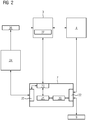
- An acyclic data register 21 is used to enable configuration of a user program 20 of a PLC 7, which can be queried and written within the PLC by the configurable user program 20 to enable the user program 20 to access the configuration parameters available for this.
- the user program 20 is freely programmable for the manufacturer of a module, later after delivery to the module user to enable protection of know-how against unauthorized reading or modification depending on the specifications of the module manufacturer. If the user program 20 is processed cyclically in the PLC 7, changes in the data register 21 are also queried cyclically. This is comparable with the access of the user program 20 to a process image 22 which is maintained for the process inputs and outputs of the PLC 7.
- An RPC interface 23 enables acyclic access to the data register 21 for the engineering tool 3, which is provided for the plant engineering.
- the RPC interface 23 is specified in an interface description with a formal description language.
- the interface description can be implemented using languages that are known from field device integration. A suitable language is, for example, EDDL.
- the configurable user program 20 can use a module engineering tool 24 which is specific to the manufacturer of the PLC 7 and uses a likewise manufacturer-specific engineering interface 25 of the PLC 7 for access to the PLC 7.
- Parameters with the definition of which the user program 20 can be configured can be marked in the user program 20 by assigning appropriate attributes.
- the configuration parameters are thus marked in the user program 20 according to the exemplary embodiment described here by a defined flag.
- the finished user program which is present as source code in the engineering tool 24, is translated by means of the module engineering tool 24 and downloaded into the PLC 7 as an executable user program 20.
- the parameters are determined using the flags, for example, and memory cells are provided for the variables in the acyclic data register 21. So that the assigned memory cells can also be made known to the system engineering tool 3, a file 26 is also created during the compilation in which the parameters in a formal description language, for example EDDL, as information for later integration of the one equipped with the PLC 7 Module in a system (1 in Figure 1 ) are included.
- the provision of the file 26 for use in system engineering takes place offline, for example by storing the file 26 in a database of the module manufacturer, which a user can access during system engineering.
- the user program 20 can be customized by configuration after the module has been completed.
- the user has a PLC 7 with a user program 20 and with which can be configured by parameters a data register 21 for the parameters for configuring the user program 20 is available.
- he is provided with a file in which the parameters are contained in a formal description language as information on the integration of the function module.
- no engineering tools that are specific for the manufacturer of the PLC 7 are required for the individualization and adaptation of the functional module when engineering the system.
- the engineering of the plant is advantageously carried out with the plant engineering tool 3.
- This can contain a tool 27 for device integration, which can be designed similar to the Simatic PDM tool, which is already known for field device integration.
- a user usually already has such an integration tool 27, which can now also be used for the integration of the functional module into the plant.
- the parameters in the acyclic data register 21 are specified by the user with the aid of the plant engineering tool 3 on the basis of the file 26 and written into the data register 21 via the RPC interface 23. By decoupling this access to the data register 21 from the cyclic data access by the user program 20, the configuration of the user program 20 can advantageously be carried out during its runtime.
- Configuration options are, for example, blocking or releasing messages as well as activating, deactivating and adapting functional parts of the user program 20.Users advantageously no longer need any control-specific engineering tools to configure and adapt the function modules used in their system, but can do an engineering -Tool 3, which is independent of the manufacturers of the controls 7 used in the function modules, configure all function modules used in its system.
- the RPC interface 23 specified with a formal description language can supplement the configuration of the user program 20 can also be used to transfer diagnostic data from the PLC 7 or the user program 20.
- a function module is generally used to carry out a basic procedural or process engineering operation or basic reaction. A distinction can be made as to whether it is an auxiliary process that is implemented by a package unit or a function that is used in the active reaction process. It is also possible to use a function module within a discrete or hybrid system. An example of a module from a hybrid system is a filling machine. The actual production process can be designed as a continuous process or as a batch process, the filling process discreet.
- a functional module is a temperature control module which provides the function of heating or cooling an object, for example with water flowing around it.
- this represents a procedural or process engineering module for use as part of the system. If the glass reactor is operated in a warm environment, the temperature loss when heating is significantly lower than when it is operated in a cold environment . This leads to different system time constants and thus to different controller parameterization. A corresponding adaptation of the controller parameters could not be implemented without a manufacturer-specific engineering system for the PLC. With the new engineering method, on the other hand, the configuration and re-parameterization of the function module can be carried out with an engineering tool that is independent of the respective manufacturer of the PLC.
- Controller parameters for pumps or flow controls depend on the viscosity of the medium to be dosed. Viscous media cannot be pumped with the same flow rate as water, for example. These differences can be transferred to the user program 20 by parameterization via the RPC interface 23 without using a manufacturer-specific engineering tool.
- the new engineering method can advantageously be used in all cases in which a control or regulating function has to be parameterized differently depending on the environment.
- the new engineering method has the advantage that they only have to program the user program 20 for the function module once to implement the desired functions.
- the adaptation and integration of the function module in the respective system can be done by parameterizing the function module using a manufacturer-independent engineering tool 3.
- the possibility is also created to operate a know-how protection, but still get a high flexibility in the application of the function module through the parameterization. This can advantageously prevent people from making unauthorized changes directly to the user program 20, for example because of a lack of knowledge, which changes could possibly lead to a disruption of the system operation.
Landscapes
- Engineering & Computer Science (AREA)
- Physics & Mathematics (AREA)
- General Physics & Mathematics (AREA)
- Automation & Control Theory (AREA)
- General Engineering & Computer Science (AREA)
- Manufacturing & Machinery (AREA)
- Quality & Reliability (AREA)
- Programmable Controllers (AREA)
- Stored Programmes (AREA)
Description
- Die Erfindung betrifft ein Verfahren zur Parametrierung einer verfahrens- oder prozesstechnischen Anlage mit zumindest einem Funktionsmodul, wobei das Funktionsmodul eine speicherprogrammierbare Steuerung (SPS) und ein mittels der SPS steuer- und/oder regelbares verfahrens- oder prozesstechnisches Modul zur Verwendung als Anlagenteil umfasst.
- Um das Engineering einer Automatisierung einer verfahrens- oder prozesstechnischen Anlage, im Folgenden kurz Anlage genannt, durchzuführen, wird in einem Anlagen-Engineering-Werkzeug üblicherweise in einem ersten Schritt die Struktur der Anlage erfasst und mittels des Werkzeugs ein R&I-Fließschema der Anlage oder von Teilen der Anlage durch Verknüpfung von graphischen Prozessobjekten erstellt. Die graphischen Prozessobjekte repräsentieren die für den Betrieb der Anlage erforderlichen Komponenten, zum Beispiel Sensoren, Motoren, Pumpen, Ventile, Rohrleitungen, Tanks, Reaktoren etc., oder sie repräsentieren Funktionsmodule, die im Zuge einer zunehmenden Modularisierung verfahrens- oder prozesstechnischer Anlagen vermehrt eingesetzt werden. Der Trend in der Verfahrens- und Prozesstechnik geht nämlich hin zu Modulen mit definierten Grundoperationen und zu deren Bereitstellung als funktionale Einheiten, den so genannten Funktionsmodulen. Im Hinblick auf die einfache Realisierbarkeit der funktionalen Aspekte der Module aus der Sicht des Engineerings der Automatisierung ist es dabei von Vorteil, wenn die Funktionsmodule mit einer eigenen Intelligenz in Form einer SPS ausgestattet sind. Die hierfür einsetzbaren Steuerungen, häufig auch als Program Logic Controller (PLC) bezeichnet, stammen unter Umständen von verschiedenen Herstellern, das heißt verschiedene in einer Anlage eingesetzte Funktionsmodule können mit voneinander abweichenden Steuerungen unterschiedlicher Hersteller ausgestattet sein. Für das Engineering der Anlage muss der Anwender dann in nachteiliger Weise Engineering-Werkzeuge sämtlicher Hersteller von Steuerungen, die in Funktionsmodulen der jeweiligen Anlage eingesetzt werden, vorhalten und anwenden können. Die Integration der Funktionsmodule sowie das Ändern oder Anpassen von Funktionen der Module zum Zeitpunkt ihrer Integration in die Anlage sind daher in nachteiliger Weise mit vergleichsweise hohem Aufwand verbunden.
- Aus der
DE 10 2010 026 494 A1 ist ein Verfahren zum Engineering eines Funktionsmoduls mit flexibel ausbaubarer Hardwarestruktur bekannt. Zur Vereinfachung der Konfiguration der im Funktionsmodul eingesetzten Steuerung je nach Ausbau der Hardwarestruktur wird mittels eines Modul-Engineering-Werkzeugs ein Steuerungsprojekt für maximalen Ausbau erstellt und gemeinsam mit einer Änderungssoftware, in welcher in Form einer Datei Änderungsinformationen enthalten sind, in eine Steuerung des Funktionsmoduls geladen. - Aus der
US 7,151,966 B1 ist ein Verfahren zum Engineering einer industriellen Anlage bekannt, gemäß welchem die Komponenten der Anlage je nach ihren verfügbaren Ressourcen ihre Dienste als Webservices innerhalb eines Steuerungsnetzwerks anbieten. - Aus der
US 8,849,431 B2 ist bekannt, ein Anwendungsprogramm einer SPS mit Hilfe einer Datei zu konfigurieren, die Informationen zu einer gewünschten Anzahl von Instanzen und zu einer gewünschten Modulkonfiguration des Anwenderprogramms enthält. Die Konfigurationsdatei wird dabei von einem herstellerspezifischen Konfigurationsgerät in die SPS geladen. Das hat den Nachteil, dass zum Engineering der Anlage wiederum Konfigurationsgeräte der verschiedenen Hersteller bereit gehalten werden müssen. - In der
JP 2004 126817 A - Der Erfindung liegt daher die Aufgabe zugrunde, ein Verfahren zum Engineering einer verfahrens- oder prozesstechnischen Anlage mit zumindest einem Funktionsmodul zu finden, das sich durch geringeren Aufwand auszeichnet.
- Zur Lösung dieser Aufgabe weist das neue Parametrierungsverfahren die in Anspruch 1 genannten Merkmale auf. Vorteilhafte Weiterbildungen der Erfindung sind in den abhängigen Ansprüchen beschrieben.
- Die Erfindung hat den Vorteil, dass eine verfahrens- oder prozesstechnische Anlage mit mehreren Funktionsmodulen, die mit Steuerungen verschiedener Hersteller ausgestattet sein können, ohne die jeweiligen herstellerspezifischen Engineering-Werkzeuge der Steuerungshersteller engineert werden kann. Der Anwender der Anlage muss sich beim Engineering seiner Anlage nicht mehr mit den verschiedenen Engineering-Werkzeugen der Steuerungshersteller befassen und sich nicht mehr das zur Bedienung dieser Werkzeuge erforderliche Spezialwissen aneignen. Für das Engineering der Anlage kann der Anwender nun vorteilhaft mit einem einzigen Anlagen-Engineering-Werkzeug auskommen.
- Das Engineering des Funktionsmoduls, welches für einen Einsatz in der Anlage vorgesehen ist, kann beim Modulhersteller durchgeführt werden. Der Hersteller des Funktionsmoduls seinerseits kann dazu spezielle Engineering-Werkzeuge verwenden, die spezifisch für den jeweiligen Hersteller der im Modul verwendeten SPS sind. Dem Modulhersteller wird somit voller Zugriff auf die Projektierung der Steuerung bei der Automatisierung des Funktionsmoduls gegeben.
- Dagegen muss einem Anwender des Funktionsmoduls zum Engineering der jeweiligen Anlage, in welcher das Modul eingesetzt wird, und insbesondere zur Integration des Funktionsmoduls in die Anlage kein vollständiger Zugriff auf die Projektierung der SPS des Funktionsmoduls gegeben werden. Durch bestimmte Parameter, die der Modulhersteller dem Anwender offenlegt, können die verschiedenen, durch den Modulhersteller realisierten funktionalen Services des Moduls aktiviert und/oder parametriert werden, so dass eine Individualisierung des Funktionsmoduls je nach Anforderungen des Anwenders ermöglicht wird.
- Der Hersteller des Funktionsmoduls erstellt dazu ein durch Parameter konfigurierbares Anwenderprogramm für eine zum Zeitpunkt der Programmerstellung frei programmierbare SPS. Dies geschieht beim Hersteller mittels eines Werkzeugs, welches zum Engineering der jeweiligen SPS und damit zum Engineering des mit der SPS versehenen Funktionsmoduls ausgebildet ist. Mittels des Werkzeugs wird das so erstellte Anwenderprogramm übersetzt und durch den Modulhersteller in die SPS heruntergeladen. Die SPS ist nun mit einem durch Parameter konfigurierbaren Anwenderprogramm versehen. Durch das Modul Engineering-Werkzeug, welches zum Engineering der SPS ausgebildet ist, kann beim Übersetzen des Anwenderprogramms automatisch eine Datei erstellt werden, in welcher die Parameter, mit denen das Anwenderprogramm konfigurierbar ist, in einer formalen Beschreibungssprache als Informationen zur Funktionsmodulintegration enthalten sind. In vorteilhafter Weise wird durch diese Vorgehensweise zudem ein Schutz des Knowhows des Modulherstellers ermöglicht, da das Anwenderprogramm zwar konfigurierbar durch den Anwender des Funktionsmoduls aber nicht lesbar oder veränderbar durch diesen sein muss.
- Für eine Auswahl und ein Festlegen der Parameter für seine anwendungsspezifische Konfiguration des Funktionsmoduls mittels des Anlagen-Engineering-Werkzeugs benötigt der Anwender lediglich Kenntnis darüber, mit welchen Parametern und wie das Funktionsmodul für eine gewünschte Funktion konfiguriert und/oder parametriert werden kann. Diese Kenntnis kann er aus der Datei mit den Informationen zur Funktionsmodulintegration erhalten. Die Festlegung der Parameter kann beispielsweise durch Eingaben des Anwenders in ein Anlagen-Engineering-Werkzeug mit einer menügeführten Bedienoberfläche erfolgen. Aufgrund der zuvor eingelesenen Datei mit den Informationen zur Funktionsmodulintegration kann der Anwender bei der Menüführung vorteilhaft zur Eingabe genau der Parameter aufgefordert werden, mit welchen das jeweilige Anwenderprogramm in der SPS des Funktionsmoduls konfigurierbar ist. Das Engineering der Anlage wird dadurch weiter vereinfacht. Mit dem Abspeichern der zuvor mittels des Anlagen-Engineering-Werkzeugs festgelegten Parameter in der SPS des Funktionsmoduls ist der Vorgang der Konfiguration des Anwenderprogramms abgeschlossen.
- Wenn die Schnittstelle, über welche der Zugriff des Anlagen-Engineering-Werkzeugs zum Abspeichern der Parameter im Datenspeicher der SPS erfolgt, als Remote Procedure Call (RPC)-Schnittstelle ausgeführt und durch eine Beschreibung in der Electronic Device Description Language (EDDL) spezifiziert ist, kann vorteilhaft auf Technologien zurückgegriffen werden, die aus dem Bereich der Feldgeräteintegration bekannt und bewährt sind. Zudem können beim Anwender möglicherweise bereits vorhandene Engineering-Werkzeuge der Feldgeräteintegration nun auch zur Integration der Funktionsmodule in Anlagen angewendet werden.
- Den Speicherbereich, der in der SPS für die Parameter zur anwendungsspezifischen Konfiguration des Funktionsmoduls vorgesehen ist, als Datenregister auszuführen, auf welches über die RPC-Schnittstelle azyklisch zugegriffen werden kann, ermöglicht dabei in vorteilhafterweise eine Änderung der Konfiguration des Funktionsmoduls auch während der Laufzeit der Anlage, so dass unter Umständen für Änderungen oder Anpassungen auf einen Anlagenstillstand und damit auf kostspielige Unterbrechungen der auf der Anlage ablaufenden Prozesse verzichtet werden kann.
- Gemäß einer besonders vorteilhaften Ausgestaltung des Verfahrens werden die Parameter, durch welche das Anwenderprogramm konfigurierbar ist, im Anwenderprogramm mit entsprechenden Kennzeichnungen versehen, anhand welcher beim Übersetzen des Anwenderprogramms die Parameter automatisch aus dem Anwenderprogramm extrahierbar sind, so dass für die Parameter jeweils Speicherzellen im Speicherbereich der SPS automatisch reserviert werden können. Die oben beschriebene Kennzeichnung der Parameter kann besonders einfach dadurch erfolgen, dass im Anwenderprogramm den Parametern jeweils ein Attribut zugewiesen wird, welches diese als den Informationen zur Funktionsmodulintegration zugehörig kennzeichnet.
- Anhand der Zeichnungen, in denen ein Ausführungsbeispiel der Erfindung dargestellt ist, werden im Folgenden die Erfindung sowie Ausgestaltungen und Vorteile näher erläutert.
- Es zeigen:
- Figur 1
- ein Beispiel einer verfahrens- oder prozesstechnischen Anlage und
- Figur 2
- ein Blockschaltbild zur Verdeutlichung des Engineerings der Anlage.
-
Figur 1 zeigt in vereinfachter schematischer Darstellung als Beispiel eine Anlage 1, in der ein Prozess 2 mittels eines Automatisierungssystems gesteuert wird. Das Automatisierungssystem enthält ein Engineering-Werkzeug 3, ein Bedien- und Beobachtungsgerät 4 und eine Vielzahl von Funktionsmodulen 5, die über ein Bussystem 6 zur Datenkommunikation miteinander verbunden sind. Der besseren Übersichtlichkeit wegen sind lediglich zwei Funktionsmodule 5 dargestellt. Die Funktionsmodule 5 steuern den Prozess 2 nach Maßgabe konfigurierbarer Anwenderprogramme, die in speicherprogrammierbaren Steuerungen 7 der Module 5 ablaufen. Zur Steuerung des Prozesses 2 werden weiterhin vielfältige Feldgeräte 8 eingesetzt, die beispielsweise über Geräte 9, so genannte dezentrale IO-Geräte, an die Steuerungen 7 angeschlossen sind. Bei den Feldgeräten 8 kann es sich beispielsweise um Messumformer handeln, welche zur Erfassung von Prozessvariablen dienen, wie beispielsweise Temperatur, Druck, Durchflussmenge, Füllstand, Dichte oder Gaskonzentration eines Mediums. Bei den Feldgeräten 8 kann es sich ebenso um Stellglieder handeln, durch welche der Prozessablauf in Abhängigkeit von erfassten Prozessvariablen den Vorgaben der in den Steuerungen 7 ablaufenden, konfigurierten Anwenderprogramme entsprechend beeinflusst werden. Als Beispiele für Stellglieder seien ein Regelventil, eine Heizung oder eine Pumpe genannt. - In
Figur 2 sind die bereits inFigur 1 eingeführten Komponenten einer Anlage mit gleichen Bezugszeichen versehen. - Gemäß dem in
Figur 2 dargestellten Ausführungsbeispiel wird zur Ermöglichung einer Konfiguration eines Anwenderprogramms 20 einer SPS 7 ein azyklisches Datenregister 21 verwendet, welches SPS-intern durch das konfigurierbare Anwenderprogramm 20 zur Ermöglichung eines Datenzugriffs des Anwenderprogramms 20 auf die für dieses zur Verfügung stehenden Konfigurationsparameter abgefragt und beschrieben werden kann. Das Anwenderprogramm 20 ist für den Hersteller eines Moduls frei programmierbar, später nach Auslieferung an den Modulanwender zur Ermöglichung eines Know-how-Schutzes vor einem unberechtigten Lesen oder Verändern je nach Vorgabe des Modulherstellers eventuell geschützt. Bei einer zyklischen Bearbeitung des Anwenderprogramms 20 in der SPS 7 werden Änderungen im Datenregister 21 ebenfalls zyklisch abgefragt. Dies ist vergleichbar mit dem Zugriff des Anwenderprogramms 20 auf ein Prozessabbild 22, welches für die Prozesseingänge und -ausgänge der SPS 7 gepflegt wird. Eine RPC-Schnittstelle 23 ermöglicht für das Engineering-Werkzeug 3, welches für das Anlagen-Engineering vorgesehen ist, einen azyklischen Zugriff auf das Datenregister 21. Die RPC-Schnittstelle 23 ist in einer Schnittstellenbeschreibung mit formaler Beschreibungssprache spezifiziert. Die Schnittstellenbeschreibung kann mit Sprachen, die aus der Feldgeräteintegration bekannt sind, realisiert werden. Eine geeignete Sprache ist beispielsweise EDDL. - Für das Engineering des Moduls selbst beim Modulhersteller, bei welchem unter anderem das konfigurierbare Anwenderprogramm 20 erstellt wird, kann dieser ein Modul-Engineering-Werkzeug 24 verwenden, welches spezifisch für den Hersteller der SPS 7 ist und eine ebenfalls herstellerspezifische Engineering-Schnittstelle 25 der SPS 7 für Zugriffe auf die SPS 7 nutzt. Parameter, mit deren Festlegung das Anwenderprogramm 20 konfigurierbar ist, können durch Zuweisung entsprechender Attribute im Anwenderprogramm 20 markiert werden. Eine dazu geeignete Programmzeile lautet beispielsweise EDDL_GROUP:="FC1013-Dosage Control"
in der Definition einer Liste von Systemattributen eines Funktionsblocks oder
EDDL:="true"
im Block der Definition einer Eingangsvariablen oder einer Ausgangsvariablen, welche Teil der RPC-Schnittstelle 23 sein soll. Die Konfigurationsparameter werden somit im Anwenderprogramm 20 gemäß dem hier beschriebenen Ausführungsbeispiel durch ein definiertes Flag markiert. Beim Modulhersteller wird mittels des Modul-Engineering-Werkzeugs 24 das fertige Anwenderprogramm, welches im Engineering-Werkzeug 24 als Source Code vorliegt, übersetzt und in die SPS 7 als ablauffähiges Anwenderprogramm 20 heruntergeladen. Beim Übersetzen werden die Parameter anhand beispielsweise der Flags ermittelt und Speicherzellen für die Variablen im azyklischen Datenregister 21 vorgesehen. Damit die zugeordneten Speicherzellen auch dem Anlagen-Engineering-Werkzeug 3 bekannt gemacht werden können, wird beim Übersetzen zusätzlich eine Datei 26 erstellt, in welcher die Paramater in einer formalen Beschreibungssprache, zum Beispiel EDDL, als Informationen zur späteren Integration des mit der SPS 7 ausgestatteten Moduls in einer Anlage (1 inFigur 1 ) enthalten sind. Die Bereitstellung der Datei 26 zur Verwendung beim Anlagen-Engineering erfolgt offline, beispielsweise durch Hinterlegung der Datei 26 in einer Datenbank des Modulherstellers, auf welche ein Anwender beim Anlagen-Engineering zugreifen kann. Das Anwenderprogramm 20 ist nach Fertigstellung des Moduls durch Konfiguration individualisierbar. Für das Anlagen-Engineering steht somit dem Anwender eine SPS 7 mit einem durch Parameter konfigurierbaren Anwenderprogramm 20 und mit einem Datenregister 21 für die Parameter zur Konfiguration des Anwenderprogramms 20 zur Verfügung. Zudem wird ihm eine Datei bereitgestellt, in welcher die Parameter in einer formalen Beschreibungssprache als Informationen zur Funktionsmodulintegration enthalten sind. Vorteilhaft werden somit für die Individualisierung und Anpassung des Funktionsmoduls beim Engineering der Anlage keinerlei Engineering-Werkzeuge mehr benötigt, die spezifisch für den Hersteller der SPS 7 sind. - Das Engineering der Anlage wird vorteilhaft mit dem Anlagen-Engineering-Werkzeug 3 durchgeführt. Dieses kann ein Werkzeug 27 zur Geräteintegration enthalten, das ähnlich dem Werkzeug Simatic PDM ausgeführt sein kann, welches bereits zur Feldgeräteintegration bekannt ist. Für das Anlagen-Engineering verfügt ein Anwender üblicherweise bereits über ein derartiges Integrationswerkzeug 27, welches nun auch für die Integration des Funktionsmoduls in die Anlage genutzt werden kann. Die Parameter im azyklischen Datenregister 21 werden durch den Anwender mit Hilfe des Anlagen-Engineering-Werkzeugs 3 auf der Basis der Datei 26 festgelegt und über die RPC-Schnittstelle 23 in das Datenregister 21 geschrieben. Durch die Entkopplung dieses Zugriffs auf das Datenregister 21 vom zyklischen Datenzugriff durch das Anwenderprogramm 20 kann in vorteilhafter Weise die Konfiguration des Anwenderprogramms 20 während dessen Laufzeit durchgeführt werden. Konfigurationsmöglichkeiten sind beispielsweise das Sperren oder Freigeben von Meldungen sowie das Aktivieren, Deaktivieren, Anpassen von funktionalen Teilen des Anwenderprogramms 20. Vorteilhaft benötigt ein Anwender zur Konfiguration und Anpassung der in seiner Anlage verwendeten Funktionsmodule keine steuerungsspezifischen Engineering-Werkzeuge mehr, sondern er kann mit einem Engineering-Werkzeug 3, welches unabhängig von den Herstellern der in den Funktionsmodulen verwendeten Steuerungen 7 ist, alle in seiner Anlage eingesetzten Funktionsmodule konfigurieren.
- Die mit einer formalen Beschreibungssprache spezifizierte RPC-Schnittstelle 23 kann ergänzend zur Konfiguration des Anwenderprogramms 20 auch zur Übertragung von Diagnosedaten der SPS 7 oder des Anwenderprogramms 20 genutzt werden.
- Ein Funktionsmodul dient allgemein zur Ausführung einer verfahrens- oder prozesstechnischen Grundoperation oder Grundreaktion. Dabei kann unterschieden werden, ob es sich um einen Hilfsprozess handelt, der durch eine Package Unit realisiert wird, oder um eine Funktion, die im aktiven Reaktionsprozess eingesetzt wird. Auch der Einsatz eines Funktionsmoduls innerhalb einer diskreten oder hybriden Anlage ist möglich. Ein Beispiel für ein Modul aus einer hybriden Anlage ist eine Abfüllmaschine. Der eigentliche Produktionsprozess kann dabei als kontinuierlicher Prozess oder als Batch-Prozess ausgelegt sein, der Abfüllprozess diskret.
- Ein weiteres Beispiel für ein Funktionsmodul ist ein Temperiermodul, welches die Funktion des Beheizens oder Kühlens eines Objekts, beispielsweise mit umströmendem Wasser, bereitstellt. Beispielsweise bei einer Realisierung eines derartigen Moduls mit einem doppelwandigen Glasreaktor stellt dieser ein verfahrens- oder prozesstechnisches Modul zur Verwendung als Teil der Anlage dar. Wird der Glasreaktor in einer warmen Umgebung betrieben, ist der Temperaturverlust beim Heizen deutlich geringer als bei einem Betrieb in kalter Umgebung. Dies führt zu abweichenden Streckenzeitkonstanten und somit zu unterschiedlicher Reglerparametrierung. Eine entsprechende Anpassung der Reglerparameter konnte bisher ohne ein herstellerspezifisches Engineering-System für die SPS nicht realisiert werden. Mit dem neuen Engineering-Verfahren kann dagegen die Konfiguration und Neuparametrierung des Funktionsmoduls mit einem Engineering-Werkzeug vorgenommen werden, welches unabhängig vom jeweiligen Hersteller der SPS ist.
- Bei einem Funktionsmodul zur Dosierung in einer prozesstechnischen Anlage ergibt sich eine ähnliche Situation. Reglerparameter für Pumpen oder Durchflussregelungen sind abhängig davon, welche Viskosität ein zu dosierendes Medium besitzt. Zähflüssige Medien können nicht mit der gleichen Durchflussrate wie beispielsweise Wasser gepumpt werden. Diese Unterschiede können durch Parametrierung über die RPC-Schnittstelle 23 ohne Verwendung eines herstellerspezifischen Engineering-Werkzeugs an das Anwenderprogramm 20 übergeben werden.
- Bei allen Fällen, in welchen eine steuerungs- oder regelungstechnische Funktion je nach Umgebung unterschiedlich zu parametrieren ist, kann das neue Engineering-Verfahren vorteilhaft angewendet werden. Für Hersteller von Funktionsmodulen hat das neue Engineering-Verfahren den Vorteil, dass sie das Anwenderprogramm 20 für das Funktionsmodul zur Realisierung der gewünschten Funktionen nur einmal programmieren müssen. Die Anpassung und Integration des Funktionsmoduls in die jeweilige Anlage kann durch Parametrierung des Funktionsmoduls mittels eines herstellerunabhängigen Engineering-Werkzeugs 3 erfolgen. Für den Hersteller des Funktionsmoduls wird zudem die Möglichkeit geschaffen, einen Know-how-Schutz zu betreiben, durch die Parametrierung aber dennoch eine hohe Flexibilität in der Anwendung des Funktionsmoduls zu erhalten. Dabei kann in vorteilhafter Weise verhindert werden, dass Personen unberechtigterweise, beispielsweise wegen fehlender Kenntnisse, Veränderungen unmittelbar am Anwenderprogramm 20 vornehmen, die möglicherweise zu einer Störung des Anlagenbetriebs führen könnten.
Claims (4)
- Verfahren zur Parametrierung einer verfahrens- oder prozesstechnischen Anlage (1) mit zumindest einem Funktionsmodul (5), wobei das Funktionsmodul (5) eine speicherprogrammierbare Steuerung (7) und ein mittels der speicherprogrammierbaren Steuerung (7) steuer- und/oder regelbares verfahrens- oder prozesstechnisches Modul zur Verwendung als Teil der Anlage umfasst und wobei die speicherprogrammierbare Steuerung (7) zumindest ein durch Parameter konfigurierbares Anwenderprogramm (20), einen Speicherbereich (21), der für die Parameter zur anwendungsspezifischen Konfiguration des Funktionsmoduls (5) vorgesehen ist, und eine Schnittstelle (23) aufweist, die durch eine Beschreibung in einer formalen Beschreibungssprache spezifiziert ist und über welche der Speicherbereich (21) mit Parametern beschreibbar ist, wobei das Verfahren die folgenden Schritte umfasst:- Bereitstellen einer dem konfigurierbaren Anwenderprogramm (20) entsprechenden Datei (26), welche mittels eines für einen Hersteller der Steuerung (7) spezifischen Modul-Engineering-Werkzeugs (24) erstellt ist und in welcher die Parameter in einer formalen Beschreibungssprache als Informationen zur Funktionsmodulintegration enthalten sind,- Einlesen der Datei (26) mit den Informationen zur Funktionsmodulintegration in ein Werkzeug (3), welches zum Engineering der Anlage (1) ausgebildet und unabhängig vom Hersteller der Steuerung (7) ist,- Festlegen der Parameter zur anwendungsspezifischen Konfiguration des Funktionsmoduls (5) mittels des Anlagen-Engineering-Werkzeugs (3) und- Abspeichern der zuvor festgelegten Parameter mittels des Anlagen-Engineering-Werkzeugs (3) in den Speicherbereich (21) durch Zugriff über die Schnittstelle (23) auf Basis der Beschreibung der Schnittstelle (23).
- Verfahren nach Anspruch 1, dadurch gekennzeichnet, dass der Speicherbereich (21) als Datenregister ausgeführt ist, auf welches azyklisch über die Schnittstelle (23) zugreifbar ist.
- Verfahren nach einem der vorhergehenden Ansprüche, dadurch gekennzeichnet, dass die Parameter, durch welche das Anwenderprogramm (20) konfigurierbar ist, im Source Code des Anwenderprogramms (20) mit entsprechenden Kennzeichnungen versehen werden und dass mittels des Modul-Engineering-Werkzeugs (24), welches ferner zum Engineering der speicherprogrammierbaren Steuerung (7) ausgebildet ist, beim Übersetzen Source Codes in ein in die speicherprogrammierbare Steuerung (7) ladbares Anwenderprogramm (20) anhand der Kennzeichnungen die Parameter, durch welche das Anwenderprogramm (20) konfigurierbar ist, bestimmt werden und für die Parameter jeweils Speicherzellen im Speicherbereich (21) reserviert werden.
- Verfahren nach Anspruch 3, dadurch gekennzeichnet, dass den Parametern, durch welche das Anwenderprogramm (20) konfigurierbar ist, im Anwenderprogramm jeweils ein Attribut zugewiesen wird, welches die Parameter als den Informationen zur Funktionsmodulintegration zugehörig kennzeichnet.
Priority Applications (3)
| Application Number | Priority Date | Filing Date | Title |
|---|---|---|---|
| EP16170003.4A EP3246773B1 (de) | 2016-05-17 | 2016-05-17 | Verfahren zur parametrierung einer verfahrens- oder prozesstechnischen anlage |
| CN201710345493.6A CN107422660A (zh) | 2016-05-17 | 2017-05-16 | 工艺或过程技术设施工程化的方法 |
| US15/596,829 US10747211B2 (en) | 2016-05-17 | 2017-05-16 | Method for engineering a method- or process-engineering plant, function module and stored program control |
Applications Claiming Priority (1)
| Application Number | Priority Date | Filing Date | Title |
|---|---|---|---|
| EP16170003.4A EP3246773B1 (de) | 2016-05-17 | 2016-05-17 | Verfahren zur parametrierung einer verfahrens- oder prozesstechnischen anlage |
Publications (2)
| Publication Number | Publication Date |
|---|---|
| EP3246773A1 EP3246773A1 (de) | 2017-11-22 |
| EP3246773B1 true EP3246773B1 (de) | 2020-11-04 |
Family
ID=56008558
Family Applications (1)
| Application Number | Title | Priority Date | Filing Date |
|---|---|---|---|
| EP16170003.4A Active EP3246773B1 (de) | 2016-05-17 | 2016-05-17 | Verfahren zur parametrierung einer verfahrens- oder prozesstechnischen anlage |
Country Status (3)
| Country | Link |
|---|---|
| US (1) | US10747211B2 (de) |
| EP (1) | EP3246773B1 (de) |
| CN (1) | CN107422660A (de) |
Families Citing this family (6)
| Publication number | Priority date | Publication date | Assignee | Title |
|---|---|---|---|---|
| EP3575904B1 (de) * | 2018-05-30 | 2023-06-28 | Siemens Aktiengesellschaft | Verfahren zur erstellung eines rezeptes für eine verfahrenstechnische prozessanlage |
| DE102018211940A1 (de) * | 2018-07-18 | 2020-01-23 | Robert Bosch Gmbh | Automatisierungsanlage, Funktionsmodul, Verfahren, Computerprogramm und Speichermedium |
| EP3657285B1 (de) * | 2018-11-26 | 2023-05-10 | Siemens Aktiengesellschaft | Einbindung von technischen modulen in eine übergeordnete steuerungsebene |
| BE1026842B1 (de) * | 2018-12-06 | 2020-07-06 | Phoenix Contact Gmbh & Co | Integration mehrerer Anlagenmodule mit jeweils wenigstens einer prozesstechnischen Einheit zu einer modular aufgebauten Gesamtanlage |
| EP3995909B1 (de) * | 2020-11-10 | 2026-01-28 | ABB Schweiz AG | Konfiguration von modularen industrieanlagen |
| US20240272600A1 (en) | 2021-06-16 | 2024-08-15 | Siemens Aktiengesellschaft | Method, Devices, Computer Program and Computer-Readable Medium for Using Configurable Logic for Modular Setup of a Technical Installation |
Citations (1)
| Publication number | Priority date | Publication date | Assignee | Title |
|---|---|---|---|---|
| JP2004126817A (ja) * | 2002-09-30 | 2004-04-22 | Omron Corp | 設定ツール装置及びプログラム製品 |
Family Cites Families (8)
| Publication number | Priority date | Publication date | Assignee | Title |
|---|---|---|---|---|
| US7151966B1 (en) * | 2002-06-04 | 2006-12-19 | Rockwell Automation Technologies, Inc. | System and methodology providing open interface and distributed processing in an industrial controller environment |
| US20060130038A1 (en) * | 2004-12-15 | 2006-06-15 | Claussen Christopher S | Apparatus, system, and method for facilitating dynamic modification of existing software objects defined in a strongly-typed programming language |
| CN101702119B (zh) * | 2009-09-01 | 2014-07-09 | 广州致远电子股份有限公司 | 面向设备的编程技术与方法 |
| DE102010026494A1 (de) * | 2010-07-07 | 2012-01-12 | Abb Ag | Verfahren zur Konfigurierung einer Steuerungseinrichtung |
| US8849431B2 (en) | 2011-03-01 | 2014-09-30 | Flow Data, Inc. | Configuration based programmable logic controller (PLC) programming |
| CN103207592B (zh) * | 2012-01-11 | 2016-04-06 | 北京美智医疗科技有限公司 | 医用x光机的程控手闸装置、程控方法及专用部件 |
| US20130254668A1 (en) * | 2012-03-23 | 2013-09-26 | Rockwell Automation Technologies, Inc. | Intelligent device-configurable icons |
| CN103336491A (zh) * | 2013-06-03 | 2013-10-02 | 上海大学 | 一种基于以太网的分布式自动化生产线系统和通信方法 |
-
2016
- 2016-05-17 EP EP16170003.4A patent/EP3246773B1/de active Active
-
2017
- 2017-05-16 US US15/596,829 patent/US10747211B2/en active Active
- 2017-05-16 CN CN201710345493.6A patent/CN107422660A/zh active Pending
Patent Citations (1)
| Publication number | Priority date | Publication date | Assignee | Title |
|---|---|---|---|---|
| JP2004126817A (ja) * | 2002-09-30 | 2004-04-22 | Omron Corp | 設定ツール装置及びプログラム製品 |
Also Published As
| Publication number | Publication date |
|---|---|
| US10747211B2 (en) | 2020-08-18 |
| US20170336782A1 (en) | 2017-11-23 |
| EP3246773A1 (de) | 2017-11-22 |
| CN107422660A (zh) | 2017-12-01 |
Similar Documents
| Publication | Publication Date | Title |
|---|---|---|
| EP1606673B1 (de) | Verfahren zur übertragung von softwarecode von einer steuereinheit zu einem feldgerät der prozessautomatisierungstechnik | |
| EP1558975B1 (de) | Verfahren zur offline-parametrierung eines feldgerätes der prozessautomatisierungstechnik | |
| EP2911024B1 (de) | Verfahren zur Inbetriebnahme eines industriellen Automatisierungsnetzwerks | |
| EP3246773A1 (de) | Verfahren zum engineering einer verfahrens- oder prozesstechnischen anlage, funktionsmodul und speicherprogrammierbare steuerung | |
| DE102009054901A1 (de) | Verfahren zur offline Bedienung eines Feldgeräts der Automatisierungstechnik | |
| EP1865394A1 (de) | Verfahren zum Austausch eines Feldgerätes der Automatisierungstechnik | |
| DE102007058606A1 (de) | Verfahren zur Integration von Geräteobjekten in ein objektbasiertes Managementsystem für Feldgeräte in der Automatisierungstechnik | |
| EP3384352B1 (de) | Verfahren und system zur optimierung der inbetriebnahme von zumindest einem einer vielzahl von feldgeräten der automatisierungstechnik | |
| DE102010063164A1 (de) | Verfahren zum Integrieren von mindestens einem Feldgerät in ein Netzwerk der Automatisierungstechnik | |
| EP1714197B1 (de) | Gerätetreiber für feldgeräte der prozessautomatisierungstechnik | |
| EP3891564B1 (de) | Integration mehrerer anlagenmodule mit jeweils wenigstens einer prozesstechnischen einheit zu einer modular aufgebauten gesamtanlage | |
| EP3554050A1 (de) | Verfahren zum sichern einer automatisierungskomponente | |
| EP3082002B1 (de) | Sicherheitssteuerung und verfahren zum steuern einer automatisierten anlage | |
| DE102008038501A1 (de) | Verfahren zum Bestimmen einer statischen Datenstruktur eines Feldgerätes | |
| EP3384353B1 (de) | Verfahren und system zur optimierung der bedienung von zumindest einem einer vielzahl von feldgeräten der automatisierungstechnik | |
| EP2018603A1 (de) | Verfahren zum parametrieren eines feldgerätes der prozessautomatisierungstechnik durch nachbildung der azyklischen dienste | |
| DE102018130649A1 (de) | Verfahren zum Analysieren des Messverhaltens eines Feldgeräts der Automatisierungstechnik in Abhängigkeit der Parametrierung des Feldgeräts | |
| EP3861413B1 (de) | Verfahren zum etablieren einer netzwerkkommunikation mittels opc ua | |
| WO2008058991A1 (de) | Verfahren zum betreiben eines nach dem blockmodell arbeitenden modularen feldgerätes der automatisierungstechnik | |
| EP4327540A1 (de) | Verfahren, vorrichtungen, computerprogramm und computerlesbares medium zur verwendung konfigurierbarer logiken für einen modularen aufbau einer technischen anlage | |
| DE102007035159B4 (de) | Verfahren zum Parametrieren von mehreren Feldgeräten der Automatisierungstechnik | |
| EP2486459B1 (de) | Feldbus-Interface und Verfahren zum Betreiben desselben | |
| DE102018123436A1 (de) | Verfahren zum Überwachen einer Anlage der Automatisierungstechnik | |
| DE102020111806A1 (de) | Verfahren zum Instandhalten einer Anlage der Automatisierungstechnik | |
| EP4453671A1 (de) | Verfahren zum austausch eines feldgeräts mit einem ersatzfeldgerät in einer messstelle einer anlage der automatisierungstechnik |
Legal Events
| Date | Code | Title | Description |
|---|---|---|---|
| PUAI | Public reference made under article 153(3) epc to a published international application that has entered the european phase |
Free format text: ORIGINAL CODE: 0009012 |
|
| STAA | Information on the status of an ep patent application or granted ep patent |
Free format text: STATUS: THE APPLICATION HAS BEEN PUBLISHED |
|
| AK | Designated contracting states |
Kind code of ref document: A1 Designated state(s): AL AT BE BG CH CY CZ DE DK EE ES FI FR GB GR HR HU IE IS IT LI LT LU LV MC MK MT NL NO PL PT RO RS SE SI SK SM TR |
|
| AX | Request for extension of the european patent |
Extension state: BA ME |
|
| STAA | Information on the status of an ep patent application or granted ep patent |
Free format text: STATUS: REQUEST FOR EXAMINATION WAS MADE |
|
| 17P | Request for examination filed |
Effective date: 20180518 |
|
| RBV | Designated contracting states (corrected) |
Designated state(s): AL AT BE BG CH CY CZ DE DK EE ES FI FR GB GR HR HU IE IS IT LI LT LU LV MC MK MT NL NO PL PT RO RS SE SI SK SM TR |
|
| STAA | Information on the status of an ep patent application or granted ep patent |
Free format text: STATUS: EXAMINATION IS IN PROGRESS |
|
| 17Q | First examination report despatched |
Effective date: 20190902 |
|
| GRAP | Despatch of communication of intention to grant a patent |
Free format text: ORIGINAL CODE: EPIDOSNIGR1 |
|
| STAA | Information on the status of an ep patent application or granted ep patent |
Free format text: STATUS: GRANT OF PATENT IS INTENDED |
|
| INTG | Intention to grant announced |
Effective date: 20200812 |
|
| GRAS | Grant fee paid |
Free format text: ORIGINAL CODE: EPIDOSNIGR3 |
|
| GRAA | (expected) grant |
Free format text: ORIGINAL CODE: 0009210 |
|
| STAA | Information on the status of an ep patent application or granted ep patent |
Free format text: STATUS: THE PATENT HAS BEEN GRANTED |
|
| AK | Designated contracting states |
Kind code of ref document: B1 Designated state(s): AL AT BE BG CH CY CZ DE DK EE ES FI FR GB GR HR HU IE IS IT LI LT LU LV MC MK MT NL NO PL PT RO RS SE SI SK SM TR |
|
| REG | Reference to a national code |
Ref country code: GB Ref legal event code: FG4D Free format text: NOT ENGLISH |
|
| REG | Reference to a national code |
Ref country code: CH Ref legal event code: EP |
|
| REG | Reference to a national code |
Ref country code: AT Ref legal event code: REF Ref document number: 1331608 Country of ref document: AT Kind code of ref document: T Effective date: 20201115 |
|
| REG | Reference to a national code |
Ref country code: DE Ref legal event code: R096 Ref document number: 502016011585 Country of ref document: DE |
|
| REG | Reference to a national code |
Ref country code: IE Ref legal event code: FG4D Free format text: LANGUAGE OF EP DOCUMENT: GERMAN |
|
| REG | Reference to a national code |
Ref country code: NL Ref legal event code: MP Effective date: 20201104 |
|
| PG25 | Lapsed in a contracting state [announced via postgrant information from national office to epo] |
Ref country code: NO Free format text: LAPSE BECAUSE OF FAILURE TO SUBMIT A TRANSLATION OF THE DESCRIPTION OR TO PAY THE FEE WITHIN THE PRESCRIBED TIME-LIMIT Effective date: 20210204 Ref country code: RS Free format text: LAPSE BECAUSE OF FAILURE TO SUBMIT A TRANSLATION OF THE DESCRIPTION OR TO PAY THE FEE WITHIN THE PRESCRIBED TIME-LIMIT Effective date: 20201104 Ref country code: PT Free format text: LAPSE BECAUSE OF FAILURE TO SUBMIT A TRANSLATION OF THE DESCRIPTION OR TO PAY THE FEE WITHIN THE PRESCRIBED TIME-LIMIT Effective date: 20210304 Ref country code: GR Free format text: LAPSE BECAUSE OF FAILURE TO SUBMIT A TRANSLATION OF THE DESCRIPTION OR TO PAY THE FEE WITHIN THE PRESCRIBED TIME-LIMIT Effective date: 20210205 Ref country code: FI Free format text: LAPSE BECAUSE OF FAILURE TO SUBMIT A TRANSLATION OF THE DESCRIPTION OR TO PAY THE FEE WITHIN THE PRESCRIBED TIME-LIMIT Effective date: 20201104 |
|
| PG25 | Lapsed in a contracting state [announced via postgrant information from national office to epo] |
Ref country code: ES Free format text: LAPSE BECAUSE OF FAILURE TO SUBMIT A TRANSLATION OF THE DESCRIPTION OR TO PAY THE FEE WITHIN THE PRESCRIBED TIME-LIMIT Effective date: 20201104 Ref country code: BG Free format text: LAPSE BECAUSE OF FAILURE TO SUBMIT A TRANSLATION OF THE DESCRIPTION OR TO PAY THE FEE WITHIN THE PRESCRIBED TIME-LIMIT Effective date: 20210204 Ref country code: SE Free format text: LAPSE BECAUSE OF FAILURE TO SUBMIT A TRANSLATION OF THE DESCRIPTION OR TO PAY THE FEE WITHIN THE PRESCRIBED TIME-LIMIT Effective date: 20201104 Ref country code: PL Free format text: LAPSE BECAUSE OF FAILURE TO SUBMIT A TRANSLATION OF THE DESCRIPTION OR TO PAY THE FEE WITHIN THE PRESCRIBED TIME-LIMIT Effective date: 20201104 Ref country code: IS Free format text: LAPSE BECAUSE OF FAILURE TO SUBMIT A TRANSLATION OF THE DESCRIPTION OR TO PAY THE FEE WITHIN THE PRESCRIBED TIME-LIMIT Effective date: 20210304 Ref country code: LV Free format text: LAPSE BECAUSE OF FAILURE TO SUBMIT A TRANSLATION OF THE DESCRIPTION OR TO PAY THE FEE WITHIN THE PRESCRIBED TIME-LIMIT Effective date: 20201104 |
|
| REG | Reference to a national code |
Ref country code: LT Ref legal event code: MG9D |
|
| PG25 | Lapsed in a contracting state [announced via postgrant information from national office to epo] |
Ref country code: HR Free format text: LAPSE BECAUSE OF FAILURE TO SUBMIT A TRANSLATION OF THE DESCRIPTION OR TO PAY THE FEE WITHIN THE PRESCRIBED TIME-LIMIT Effective date: 20201104 |
|
| PG25 | Lapsed in a contracting state [announced via postgrant information from national office to epo] |
Ref country code: RO Free format text: LAPSE BECAUSE OF FAILURE TO SUBMIT A TRANSLATION OF THE DESCRIPTION OR TO PAY THE FEE WITHIN THE PRESCRIBED TIME-LIMIT Effective date: 20201104 Ref country code: SK Free format text: LAPSE BECAUSE OF FAILURE TO SUBMIT A TRANSLATION OF THE DESCRIPTION OR TO PAY THE FEE WITHIN THE PRESCRIBED TIME-LIMIT Effective date: 20201104 Ref country code: EE Free format text: LAPSE BECAUSE OF FAILURE TO SUBMIT A TRANSLATION OF THE DESCRIPTION OR TO PAY THE FEE WITHIN THE PRESCRIBED TIME-LIMIT Effective date: 20201104 Ref country code: CZ Free format text: LAPSE BECAUSE OF FAILURE TO SUBMIT A TRANSLATION OF THE DESCRIPTION OR TO PAY THE FEE WITHIN THE PRESCRIBED TIME-LIMIT Effective date: 20201104 Ref country code: SM Free format text: LAPSE BECAUSE OF FAILURE TO SUBMIT A TRANSLATION OF THE DESCRIPTION OR TO PAY THE FEE WITHIN THE PRESCRIBED TIME-LIMIT Effective date: 20201104 Ref country code: LT Free format text: LAPSE BECAUSE OF FAILURE TO SUBMIT A TRANSLATION OF THE DESCRIPTION OR TO PAY THE FEE WITHIN THE PRESCRIBED TIME-LIMIT Effective date: 20201104 |
|
| REG | Reference to a national code |
Ref country code: DE Ref legal event code: R097 Ref document number: 502016011585 Country of ref document: DE |
|
| PG25 | Lapsed in a contracting state [announced via postgrant information from national office to epo] |
Ref country code: DK Free format text: LAPSE BECAUSE OF FAILURE TO SUBMIT A TRANSLATION OF THE DESCRIPTION OR TO PAY THE FEE WITHIN THE PRESCRIBED TIME-LIMIT Effective date: 20201104 |
|
| PLBE | No opposition filed within time limit |
Free format text: ORIGINAL CODE: 0009261 |
|
| STAA | Information on the status of an ep patent application or granted ep patent |
Free format text: STATUS: NO OPPOSITION FILED WITHIN TIME LIMIT |
|
| 26N | No opposition filed |
Effective date: 20210805 |
|
| PG25 | Lapsed in a contracting state [announced via postgrant information from national office to epo] |
Ref country code: AL Free format text: LAPSE BECAUSE OF FAILURE TO SUBMIT A TRANSLATION OF THE DESCRIPTION OR TO PAY THE FEE WITHIN THE PRESCRIBED TIME-LIMIT Effective date: 20201104 Ref country code: NL Free format text: LAPSE BECAUSE OF FAILURE TO SUBMIT A TRANSLATION OF THE DESCRIPTION OR TO PAY THE FEE WITHIN THE PRESCRIBED TIME-LIMIT Effective date: 20201104 |
|
| PG25 | Lapsed in a contracting state [announced via postgrant information from national office to epo] |
Ref country code: SI Free format text: LAPSE BECAUSE OF FAILURE TO SUBMIT A TRANSLATION OF THE DESCRIPTION OR TO PAY THE FEE WITHIN THE PRESCRIBED TIME-LIMIT Effective date: 20201104 |
|
| REG | Reference to a national code |
Ref country code: CH Ref legal event code: PL |
|
| PG25 | Lapsed in a contracting state [announced via postgrant information from national office to epo] |
Ref country code: CH Free format text: LAPSE BECAUSE OF NON-PAYMENT OF DUE FEES Effective date: 20210531 Ref country code: MC Free format text: LAPSE BECAUSE OF FAILURE TO SUBMIT A TRANSLATION OF THE DESCRIPTION OR TO PAY THE FEE WITHIN THE PRESCRIBED TIME-LIMIT Effective date: 20201104 Ref country code: LU Free format text: LAPSE BECAUSE OF NON-PAYMENT OF DUE FEES Effective date: 20210517 Ref country code: LI Free format text: LAPSE BECAUSE OF NON-PAYMENT OF DUE FEES Effective date: 20210531 |
|
| REG | Reference to a national code |
Ref country code: BE Ref legal event code: MM Effective date: 20210531 |
|
| PG25 | Lapsed in a contracting state [announced via postgrant information from national office to epo] |
Ref country code: IE Free format text: LAPSE BECAUSE OF NON-PAYMENT OF DUE FEES Effective date: 20210517 |
|
| PG25 | Lapsed in a contracting state [announced via postgrant information from national office to epo] |
Ref country code: IS Free format text: LAPSE BECAUSE OF FAILURE TO SUBMIT A TRANSLATION OF THE DESCRIPTION OR TO PAY THE FEE WITHIN THE PRESCRIBED TIME-LIMIT Effective date: 20210304 |
|
| REG | Reference to a national code |
Ref country code: AT Ref legal event code: MM01 Ref document number: 1331608 Country of ref document: AT Kind code of ref document: T Effective date: 20210517 |
|
| PG25 | Lapsed in a contracting state [announced via postgrant information from national office to epo] |
Ref country code: BE Free format text: LAPSE BECAUSE OF NON-PAYMENT OF DUE FEES Effective date: 20210531 |
|
| PG25 | Lapsed in a contracting state [announced via postgrant information from national office to epo] |
Ref country code: AT Free format text: LAPSE BECAUSE OF NON-PAYMENT OF DUE FEES Effective date: 20210517 |
|
| PG25 | Lapsed in a contracting state [announced via postgrant information from national office to epo] |
Ref country code: HU Free format text: LAPSE BECAUSE OF FAILURE TO SUBMIT A TRANSLATION OF THE DESCRIPTION OR TO PAY THE FEE WITHIN THE PRESCRIBED TIME-LIMIT; INVALID AB INITIO Effective date: 20160517 |
|
| PG25 | Lapsed in a contracting state [announced via postgrant information from national office to epo] |
Ref country code: CY Free format text: LAPSE BECAUSE OF FAILURE TO SUBMIT A TRANSLATION OF THE DESCRIPTION OR TO PAY THE FEE WITHIN THE PRESCRIBED TIME-LIMIT Effective date: 20201104 |
|
| PG25 | Lapsed in a contracting state [announced via postgrant information from national office to epo] |
Ref country code: MK Free format text: LAPSE BECAUSE OF FAILURE TO SUBMIT A TRANSLATION OF THE DESCRIPTION OR TO PAY THE FEE WITHIN THE PRESCRIBED TIME-LIMIT Effective date: 20201104 |
|
| PGFP | Annual fee paid to national office [announced via postgrant information from national office to epo] |
Ref country code: GB Payment date: 20240603 Year of fee payment: 9 |
|
| PG25 | Lapsed in a contracting state [announced via postgrant information from national office to epo] |
Ref country code: MT Free format text: LAPSE BECAUSE OF FAILURE TO SUBMIT A TRANSLATION OF THE DESCRIPTION OR TO PAY THE FEE WITHIN THE PRESCRIBED TIME-LIMIT Effective date: 20201104 |
|
| PGFP | Annual fee paid to national office [announced via postgrant information from national office to epo] |
Ref country code: IT Payment date: 20250527 Year of fee payment: 10 |
|
| PGFP | Annual fee paid to national office [announced via postgrant information from national office to epo] |
Ref country code: FR Payment date: 20250516 Year of fee payment: 10 |
|
| PGFP | Annual fee paid to national office [announced via postgrant information from national office to epo] |
Ref country code: DE Payment date: 20250718 Year of fee payment: 10 |
|
| PG25 | Lapsed in a contracting state [announced via postgrant information from national office to epo] |
Ref country code: TR Free format text: LAPSE BECAUSE OF FAILURE TO SUBMIT A TRANSLATION OF THE DESCRIPTION OR TO PAY THE FEE WITHIN THE PRESCRIBED TIME-LIMIT Effective date: 20201104 |
|
| GBPC | Gb: european patent ceased through non-payment of renewal fee |
Effective date: 20250517 |
|
| PG25 | Lapsed in a contracting state [announced via postgrant information from national office to epo] |
Ref country code: GB Free format text: LAPSE BECAUSE OF NON-PAYMENT OF DUE FEES Effective date: 20250517 |